EP3371813B1 - Injektor einer isolierten lösung mit einer isolierenden auskleidung, system damit und verfahren zum injizieren damit - Google Patents
Injektor einer isolierten lösung mit einer isolierenden auskleidung, system damit und verfahren zum injizieren damit Download PDFInfo
- Publication number
- EP3371813B1 EP3371813B1 EP16794813.2A EP16794813A EP3371813B1 EP 3371813 B1 EP3371813 B1 EP 3371813B1 EP 16794813 A EP16794813 A EP 16794813A EP 3371813 B1 EP3371813 B1 EP 3371813B1
- Authority
- EP
- European Patent Office
- Prior art keywords
- solution
- injector
- inner tube
- base portion
- insulated
- Prior art date
- Legal status (The legal status is an assumption and is not a legal conclusion. Google has not performed a legal analysis and makes no representation as to the accuracy of the status listed.)
- Active
Links
Images


Classifications
-
- C—CHEMISTRY; METALLURGY
- C23—COATING METALLIC MATERIAL; COATING MATERIAL WITH METALLIC MATERIAL; CHEMICAL SURFACE TREATMENT; DIFFUSION TREATMENT OF METALLIC MATERIAL; COATING BY VACUUM EVAPORATION, BY SPUTTERING, BY ION IMPLANTATION OR BY CHEMICAL VAPOUR DEPOSITION, IN GENERAL; INHIBITING CORROSION OF METALLIC MATERIAL OR INCRUSTATION IN GENERAL
- C23F—NON-MECHANICAL REMOVAL OF METALLIC MATERIAL FROM SURFACE; INHIBITING CORROSION OF METALLIC MATERIAL OR INCRUSTATION IN GENERAL; MULTI-STEP PROCESSES FOR SURFACE TREATMENT OF METALLIC MATERIAL INVOLVING AT LEAST ONE PROCESS PROVIDED FOR IN CLASS C23 AND AT LEAST ONE PROCESS COVERED BY SUBCLASS C21D OR C22F OR CLASS C25
- C23F15/00—Other methods of preventing corrosion or incrustation
-
- G—PHYSICS
- G21—NUCLEAR PHYSICS; NUCLEAR ENGINEERING
- G21C—NUCLEAR REACTORS
- G21C19/00—Arrangements for treating, for handling, or for facilitating the handling of, fuel or other materials which are used within the reactor, e.g. within its pressure vessel
-
- C—CHEMISTRY; METALLURGY
- C23—COATING METALLIC MATERIAL; COATING MATERIAL WITH METALLIC MATERIAL; CHEMICAL SURFACE TREATMENT; DIFFUSION TREATMENT OF METALLIC MATERIAL; COATING BY VACUUM EVAPORATION, BY SPUTTERING, BY ION IMPLANTATION OR BY CHEMICAL VAPOUR DEPOSITION, IN GENERAL; INHIBITING CORROSION OF METALLIC MATERIAL OR INCRUSTATION IN GENERAL
- C23C—COATING METALLIC MATERIAL; COATING MATERIAL WITH METALLIC MATERIAL; SURFACE TREATMENT OF METALLIC MATERIAL BY DIFFUSION INTO THE SURFACE, BY CHEMICAL CONVERSION OR SUBSTITUTION; COATING BY VACUUM EVAPORATION, BY SPUTTERING, BY ION IMPLANTATION OR BY CHEMICAL VAPOUR DEPOSITION, IN GENERAL
- C23C18/00—Chemical coating by decomposition of either liquid compounds or solutions of the coating forming compounds, without leaving reaction products of surface material in the coating; Contact plating
- C23C18/02—Chemical coating by decomposition of either liquid compounds or solutions of the coating forming compounds, without leaving reaction products of surface material in the coating; Contact plating by thermal decomposition
- C23C18/08—Chemical coating by decomposition of either liquid compounds or solutions of the coating forming compounds, without leaving reaction products of surface material in the coating; Contact plating by thermal decomposition characterised by the deposition of metallic material
-
- C—CHEMISTRY; METALLURGY
- C23—COATING METALLIC MATERIAL; COATING MATERIAL WITH METALLIC MATERIAL; CHEMICAL SURFACE TREATMENT; DIFFUSION TREATMENT OF METALLIC MATERIAL; COATING BY VACUUM EVAPORATION, BY SPUTTERING, BY ION IMPLANTATION OR BY CHEMICAL VAPOUR DEPOSITION, IN GENERAL; INHIBITING CORROSION OF METALLIC MATERIAL OR INCRUSTATION IN GENERAL
- C23F—NON-MECHANICAL REMOVAL OF METALLIC MATERIAL FROM SURFACE; INHIBITING CORROSION OF METALLIC MATERIAL OR INCRUSTATION IN GENERAL; MULTI-STEP PROCESSES FOR SURFACE TREATMENT OF METALLIC MATERIAL INVOLVING AT LEAST ONE PROCESS PROVIDED FOR IN CLASS C23 AND AT LEAST ONE PROCESS COVERED BY SUBCLASS C21D OR C22F OR CLASS C25
- C23F11/00—Inhibiting corrosion of metallic material by applying inhibitors to the surface in danger of corrosion or adding them to the corrosive agent
-
- G—PHYSICS
- G21—NUCLEAR PHYSICS; NUCLEAR ENGINEERING
- G21C—NUCLEAR REACTORS
- G21C17/00—Monitoring; Testing ; Maintaining
- G21C17/02—Devices or arrangements for monitoring coolant or moderator
- G21C17/022—Devices or arrangements for monitoring coolant or moderator for monitoring liquid coolants or moderators
- G21C17/0225—Chemical surface treatment, e.g. corrosion
-
- G—PHYSICS
- G21—NUCLEAR PHYSICS; NUCLEAR ENGINEERING
- G21C—NUCLEAR REACTORS
- G21C19/00—Arrangements for treating, for handling, or for facilitating the handling of, fuel or other materials which are used within the reactor, e.g. within its pressure vessel
- G21C19/28—Arrangements for introducing fluent material into the reactor core; Arrangements for removing fluent material from the reactor core
-
- Y—GENERAL TAGGING OF NEW TECHNOLOGICAL DEVELOPMENTS; GENERAL TAGGING OF CROSS-SECTIONAL TECHNOLOGIES SPANNING OVER SEVERAL SECTIONS OF THE IPC; TECHNICAL SUBJECTS COVERED BY FORMER USPC CROSS-REFERENCE ART COLLECTIONS [XRACs] AND DIGESTS
- Y02—TECHNOLOGIES OR APPLICATIONS FOR MITIGATION OR ADAPTATION AGAINST CLIMATE CHANGE
- Y02E—REDUCTION OF GREENHOUSE GAS [GHG] EMISSIONS, RELATED TO ENERGY GENERATION, TRANSMISSION OR DISTRIBUTION
- Y02E30/00—Energy generation of nuclear origin
- Y02E30/30—Nuclear fission reactors
Definitions
- the present disclosure relates to devices, systems, and methods directed to the injection of solutions into a high-temperature environment.
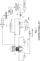
- FIG. 1 is a schematic view of a conventional boiling water nuclear reactor (BWR) including deposition solution injection.
- a hydrogen injection system 2 may be used to inject hydrogen into a feed-water suction line 4b (the suction line 4b is the inlet to feed-water pumps 10) to act as an oxygen scavenger for the water circulating in the reactor 8.
- a noble metal (e.g., platinum) deposition solution injection system 6 may be used to inject a deposition solution into the feed-water discharge line 4a in order to deposit platinum ions on surfaces of the reactor 8.
- the reactor 8 is depicted as a Boiling Water Reactor (BWR) in FIG. 1 , it should be understood that other types of nuclear reactors could also make use of deposition solution injections (such as the platinum deposition solution described herein).
- the platinum deposition solution may be, for example, a platinum salt solution of sodium hexahydroxyplatinate (Na 2 Pt(OH) 6 ).
- Ni 2 Pt(OH) 6 sodium hexahydroxyplatinate
- platinum ions may deposit onto surfaces of the reactor 8 so that the platinum may act as a catalyst to react the injected hydrogen with oxygen molecules that may be present in the reactor.
- water (H 2 O) molecules may be produced. This reaction acts to reduce and potentially eliminate oxygen molecules present on surfaces of the reactor 8 that may otherwise promote corrosion of metal components, thereby extending the useful life of reactor components.
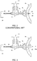
- FIG. 2 is a side, cross-sectional view of a conventional deposition solution injector configuration.
- a conventional deposition solution injector configuration 12 may include a chemical feed skid 24 supplying a deposition solution to the feed-water discharge line 4a.
- the chemical feed skid 24 typically provides the chemical deposition solution at ambient temperatures with a flow-rate of around 50-120 cm 3 /minute and a pressure typically less than 1250 psi (via positive displacement pumps).
- a chemical feed line 26 may provide the deposition solution from the chemical feed skid 24 to the injection tap 20.
- One or more injector valves 14 may be included in the chemical feed line 26 to provide a shutoff for the deposition solution in the chemical feed line 26.
- a pipe stub 16 is included at the injector valve 14 discharge.
- a weldment 18 may connect the injection tap 20 to the pipe stub 16 and feed-water discharge line 4a.
- a deposited material 22 may form within the distal end of the injection tap 20.
- the deposited material 22 may form at the injection point, as the ambient (i.e., low) temperature deposition solution is mixed with an intruding eddy flow of the high temperature, high velocity feed-water (ranging between 260 and 420 °F with a flow velocity of about 10-20 ft/sec) that may cause the deposition solution to break down into platinum ions which are then deposited within the inner distal end of the injection tap 20 (it is noted that sodium hexahydroxyplatinate, Na 2 Pt(OH) 6 , begins to break down at temperatures of 300-500°F).
- Blockage of the injection tap 20 caused by the deposited material 22 may cause the positive displacement pumps to increase injection pressure to provide the specified injection flow rate. Pressure may increase to the design pressure of the deposition solution injector configuration 12, resulting in termination of an injection before all of the deposition solution is injected. This may cause a reduced amount of platinum to be deposited within the reactor 8, itself. Furthermore, blockage of the injection tap 20 may prevent performance of the next scheduled injection (typically done once per year), or require an unplanned reactor shutdown to remove the blockage.
- smearing of deposited material 22 may also occur along the inner surfaces of the feed-water discharge line 4a as the slowly flowing deposition solution is unable to escape the boundary layer and enter the bulk flow of the feed-water.
- the smearing may cause significant amounts of platinum ions to deposit along the inside of the feed-water discharge line 4a where it is not needed or desired, which may consequently reduce the amount of platinum that reaches the reactor 8.
- Holm, Per et al. (WO 2004/056487 ) relates to a self-cleaning spray nozzle and in particular to a self-cleaning spray nozzle for use in an apparatus for the preparation of a particulate material by a controlled agglomeration method, i.e. a method for controlled growth of particle size.
- the apparatus is especially suitable for use in the preparation of pharmaceutical compositions containing a therapeutically and/or prophylactically active substance which has a relatively low aqueous solubility and/or which is subject to chemical decomposition.
- Caine, Thomas Alfred et al. discloses an insulated solution injector including an outer tube and an inner tube arranged within the outer tube.
- the outer tube and the inner tube may define an annular space therebetween, and the inner tube may define a solution space within.
- the annular space may be configured so as to insulate the solution within the solution space.
- the solution may be kept to a temperature below its decomposition temperature prior to injection. Accordingly, the decomposition of the solution and the resulting deposition of its constituents within the solution space may be reduced or prevented, thereby decreasing or precluding the occurrence of a blockage.
- Kazushiga, Ishida et al. discloses production of an aqueous solution of alkali hexahydroxo platinate.
- a alkali hexahydroxo platinate sodium hexahydroxoplatinate or potassium hexahydroxoplatinate is used.
- the aqueous solution of alkali hexahydroxo platinate is passed through a hydrogen form cation exchange resin layer in a cation exchange resin tower.
- the aqueous solution of alkali hexahydroxo platinate makes contact with the hydrogen form cation exchange resin of the hydrogen form cation exchange resin layer, thus a suspension of hexahydroxo platinic is generated. If gamma rays are irradiated to the suspension, a platinum oxide colloidal solution in which colloidal particles including a platinum dioxide, a platinum monoxide, and a platinum hydroxide exist is generated. In a platinum oxide colloidal solution, the content of impurities is little and a noble metal compound is dispersed stably in water.
- an insulated solution injector as defined by independent claim 1, and a method of injecting a solution into a high temperature liquid stream as defined by independent claim 14. Further advantageous features of the invention are defined by the dependent claims.
- An insulated solution injector includes an outer tube having a first outer surface and a first inner surface.
- An inner tube extends into the outer tube.
- the inner tube has a second outer surface and a second inner surface.
- the first inner surface of the outer tube and the second outer surface of the inner tube define an annular space therebetween, and the second inner surface of the inner tube defines a solution space.
- the annular space is isolated from the solution space.
- the outer tube may be shorter than the inner tube. As a result, a proximal end of the outer tube may be connected to the second outer surface of the inner tube.
- the inner tube may extend coaxially into the outer tube.
- An injection tip is connected to distal ends of the outer tube and the inner tube.
- the injection tip includes a base portion and a shield portion projecting from the base portion.
- the shield portion extends along a periphery of the base portion of the injection tip.
- the base portion and the shield portion may be in a form of a monolithic structure.
- the shield portion may have an angled distal surface.
- the base portion of the injection tip has a hole extending therethrough. The hole is in communication with the solution space within the inner tube 204.
- the inner tube may be inserted into a recess in the base portion of the injection tip, wherein the recess surrounds the hole and is on an opposite side of the base portion from the shield portion.
- An insulating liner is disposed within the inner tube and the hole of the injection tip.
- the insulating liner includes a body section, a neck section, and a lip section.
- the body section is configured to fit within the distal end of the inner tube.
- the neck section is configured to extend through the hole in the base portion of the injection tip.
- the lip section is configured to be on an opposite side of the base portion from the body section. The lip section has a larger diameter than the neck section.
- the insulating liner is formed of a material that has a melting point of at least 260 degrees Celsius.
- the material may be a fluoropolymer.
- the fluoropolymer may be polytetrafluoroethylene, which may be optionally filled to attain enhanced physical properties.
- the polytetrafluoroethylene may be filled with at least one of glass fibers, carbon, and graphite.
- the glass fibers may be present in an amount ranging from 5% to 40% by weight.
- the carbon may be present in an amount ranging from 10% to 35% by weight.
- the graphite may be present in an amount ranging from 5% to 15% by weight.
- a method of injecting a solution into a high temperature liquid stream includes inserting an injector into a pipe configured to carry a flow of the high temperature liquid stream.
- the injector is configured to deliver the solution into the high temperature liquid stream.
- the injector includes an outer tube and an inner tube extending into the outer tube.
- the outer tube and the inner tube define an annular space therebetween, while the inner tube defines a solution space therein.
- the method additionally includes insulating the solution from the high temperature liquid stream with a liner within the inner tube.
- the method additionally includes injecting the solution into the high temperature liquid stream. Furthermore, the method includes shielding the solution from a full velocity of the flow during the injecting.
- first, second, third, etc. may be used herein to describe various elements, components, regions, layers and/or sections, these elements, components, regions, layers, and/or sections should not be limited by these terms. These terms are only used to distinguish one element, component, region, layer, or section from another region, layer, or section. Thus, a first element, component, region, layer, or section discussed below could be termed a second element, component, region, layer, or section without departing from the teachings of example embodiments.
- spatially relative terms e.g., "beneath,” “below,” “lower,” “above,” “upper,” and the like
- the spatially relative terms are intended to encompass different orientations of the device in use or operation in addition to the orientation depicted in the figures. For example, if the device in the figures is turned over, elements described as “below” or “beneath” other elements or features would then be oriented “above” the other elements or features. Thus, the term “below” may encompass both an orientation of above and below.
- the device may be otherwise oriented (rotated 90 degrees or at other orientations) and the spatially relative descriptors used herein interpreted accordingly.
- Example embodiments are described herein with reference to cross-sectional illustrations that are schematic illustrations of idealized embodiments (and intermediate structures) of example embodiments. As such, variations from the shapes of the illustrations as a result, for example, of manufacturing techniques and/or tolerances, are to be expected. Thus, example embodiments should not be construed as limited to the shapes of regions illustrated herein but are to include deviations in shapes that result, for example, from manufacturing. The regions illustrated in the figures are schematic in nature and their shapes are not intended to illustrate the actual shape of a region of a device and are not intended to limit the scope of example embodiments.
- FIG. 3 is a side, cross-sectional view of a deposition solution injector configuration.
- the deposition solution injector configuration 32 includes a hollow injector tube 30 with a distal end 30a that extends beyond the inner surface of the feed-water discharge line 4a.
- the distal end 30a of the injector tube 30 may extend beyond a determined boundary layer of the bulk flow of fluids traveling through the feed-water discharge line 4a.
- the depth of the boundary layer (and, the required length X of the distal end 30a of the injector tube 30) may vary depending upon the temperature and velocity of the feed-water.
- the depth of the boundary layer may also vary depending on the type of fluid flowing in the feed-water discharge line 4a (with potentially varying viscosity), the diameter and material of the feed-water discharge line 4a, as well as other parameters known to impact the Reynolds number (and resulting boundary layer depth) of fluid flowing in the feed-water discharge line 4a. It should therefore be understood that the length X should at least be long enough to extend beyond the boundary layer of the fluid flowing in the feed-water discharge line 4a.
- the deposition solution injector configuration 32 also includes a wide diameter pipe stub 16a with an inner diameter that matches or slightly exceeds the outer diameter of the injector tube 30.
- the wide diameter pipe stub 16a provides support to minimize vibration stresses in the injector tube 30 caused by feed-water flow forces.
- the inner diameter of the injector tube 30 may also contribute to potential blockage caused by deposited material, if the deposition material is heated to high temperatures (e.g., temperatures at or above the decomposition temperature of the deposition material) as it flows to the distal end 30a of the injector tube 30. For this reason, the inside diameter of the injector tube 30 should be sized to be sufficiently small, ensuring that the deposition solution flows relatively quickly through the hot region adjacent to the feed-water discharge line 4a. For a 50-120 cm 3 /minute flow rate of deposition solution through the injector tube 30, a 1/8 inch inner diameter of the injector tube 30 would result in flow velocities of 3-9 inches/second. This would cause the deposition solution to be in the hot region for less than a second, thereby ensuring that the deposition solution does not degrade during this short period.
- high temperatures e.g., temperatures at or above the decomposition temperature of the deposition material
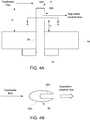
- FIG. 4A is a side, cross-sectional view of a distal end of a deposition solution injector configuration.
- the injector tube 30 is provided with an injection slot 30b located on a downstream side of the injector tube 30 (specifically, the injector slot 30b is downstream of the feed-water flow passing across the distal end 30a of the injector tube 30).
- the injection slot 30b is somewhat sheltered from the high pressure flow of the feed-water, thereby reducing the potential for the injector tube 30 to become clogged by deposited material.
- the injector tube 30 should be adequately sized to ensure that the entire injection slot 30b extends beyond the boundary layer of the flowing feed-water, just as the distal end 30a of the injector tube 30 should extend beyond the boundary layer (as described in FIG. 3 ). This ensures that the deposition solution may be fully injected into the bulk flow of feed-water in the feed-water discharge line 4a without experiencing unnecessarily high deposition of platinum ions on the inside of the feed-water discharge line 4a. For this reason, length Y (the injector tube 30 length from the inner surface of the feed-water discharge line 4a to the opening of the injection slot 30b) must extend beyond the boundary layer of the feed-water. As described in FIG.
- the boundary layer depth may vary depending on the temperature and velocity of the feed-water, the type of fluid flowing in the feed-water line, the diameter and material of the feed-water line, etc. As an example, for a 16 inch diameter feed-water discharge line 4a with flowing water in a range of 15-20 feet/second at a temperature of 260-420 °F, a length Y of 1 inch is adequate to ensure that the entire injection slot 30b extends beyond the boundary layer of the fluids flowing in the feed-water discharge line 4a.
- the size of the injection slot 30b itself may also impact the potential blockage of the injector tube 30. Therefore, the cross-sectional area of the injection slot 30b should be properly sized to ensure that the exit velocity of the deposition solution approximately matches the feed-water flow velocity, thereby ensuring that feed-water eddy flows do not enter the injection slot 30b and cause deposition and possible blockage.
- the injection slot 30b may be located a distance below the terminus of the distal end 30a of the injector tube 30 to further shelter the injection slot 30b from the high pressures of the feed-water flow.
- the distal end 30a of the injector tube 30 should not extend too far beyond the depth of the feed-water boundary layer. By not extending the distal end 30a of the injector tube 30 too far beyond the location of the boundary layer, the risk of bending and damage to the injector tube 30 by the high velocity feed-water flow may be reduced or avoided.
- the length X (the full length of the distal end 30a of the injector tube 30 extending within the feed-water discharge line 4a) is not more than about 20% greater than the required length Y. In another non-limiting embodiment, the difference between X and Y is not more than one inch.
- FIG. 4B is a top, cross-sectional view along line A-A of the deposition solution injector configuration of FIG. 4A .
- the injection slot 30b may be located on a downstream side of the injector tube 30 (the downstream side means downstream of the feed-water flow direction).
- the axial, cross-sectional profile 30c of the injector tube 30 may be a tapered, oval-shape with two acute ends (as shown in FIG. 4B ) to hydrodynamically reduce feed-water fluid forces that may be experienced at the interface between the injection slot 30b and the bulk flow of the feed-water.
- the injection slot 30b may be located on the downstream-facing acute end of the injector tube 30 (as shown in FIG. 4B ).
- the axial, cross-sectional profile 30c may also be circular, square, or other suitable shape, so long as the injection slot 30b is located on the downstream side of the injector tube 30 to minimize eddy flow of incident feed-water that may enter into the injector tube 30. Furthermore, premature decomposition and deposition of the solution may be reduced or prevented by hindering the transfer of heat to the solution during the passage of the solution through the injector to the feed-water. Such hindering of the transfer of heat may be achieved with an insulated solution injector.
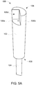
- FIG. 5A is an upper perspective view of an insulated solution injector.
- FIG. 5B is a lower perspective view of an insulated solution injector.
- FIG. 6 is a side, cross-sectional view of an insulated solution injector.
- the insulated solution injector 100 includes an arrangement of an inner tube 104 within an outer tube 102.
- the outer tube 102 has a first outer surface 102a and a first inner surface 102b.
- the inner tube 104 has a second outer surface 104a and a second inner surface 104b.
- the second outer surface 104a of the inner tube 104 is spaced apart from the first inner surface 102b of the outer tube 102.
- the first inner surface 102b of the outer tube 102 and the second outer surface 104a of the inner tube 104 define an annular space 103.
- An insulating layer may occupy the annular space 103 between the outer tube 102 and the inner tube 104.
- the insulating layer may be a gas layer.
- the inner tube 104 may be concentrically arranged within the outer tube 102.
- the second inner surface 104b of the inner tube 104 defines a solution space 105.
- the annular space 103 is isolated from the solution space 105.
- An inboard end section 106 is at a distal end of the outer tube 102 and the inner tube 104.
- the inboard end section 106 includes a base portion 106a and a shield portion 106b projecting from the base portion 106a.
- the base portion 106a has a hole 106c extending therethrough.
- the hole 106c is in communication with the solution space 105.
- the hole 106c extending through the base portion 106a may have a diameter ranging from 0.1 to 0.3 inches.
- the shield portion 106b has a groove 106d extending along a length thereof from the base portion 106a.
- the groove 106d may be V-shaped and extend along an entire length of the shield portion 106b such that the inboard end section 106 has a "pac-man" shape based on a plan view.
- the groove 106d of the shield portion 106b exposes a wedge-shaped area of the base portion 106a.
- the hole 106c extends through the wedge-shaped area of the base portion 106a.
- the groove 106d may also be U-shaped or another suitable shape. A portion or more of the side of the shield portion 106b opposite to the groove 106d may be slanted or inclined. Additionally, the terminus of the shield portion 106b may be leveled.
- An outboard end section 108 is at an opposing proximal end of the outer tube 102 and the inner tube 104 relative to the inboard end section 106.
- the outboard end section 108 may have an opening configured to allow atmospheric air to enter and circulate within the annular space 103 by natural convection.
- the insulated solution injector 100 may be installed such that the outboard end section 108 points upward to allow the higher temperature air circulating in the annular space 103 to escape by natural convection.
- the annular space 103 may be sealed, wherein the annular space 103 is filled with a gas layer or rendered as a vacuum.
- the insulated solution injector 100 is shown in the drawings as being in a linear form, it should be understood that example embodiments are not limited thereto.
- the insulated solution injector 100 may alternatively be in a curved form.
- the insulated solution injector 100 may have an inboard end section 106 that is straight to facilitate insertion into a pipe (e.g., feed-water pipe), while the outboard end section 108 may be curved to accommodate a particular configuration (and/or to maneuver around an adjacent structure), vice versa, or both curved based on situational needs.
- FIG. 7 is a side, cross-sectional view of an injection system.
- FIG. 8 is a top view along line B-B of the insulated solution injector of the injection system of FIG. 7 .
- an injection system 400 includes a pipe 402 having an exterior surface 402a and an interior surface 402b.
- the pipe 402 may be a feed-water pipe.
- the interior surface 402b of the pipe 402 defines a flow space therein for a liquid stream (e.g., feed-water).
- An insulated solution injector 100 penetrates the pipe 402. Although the insulated solution injector 100 is shown in the drawings as penetrating an underside of the pipe 402, it should be understood that example embodiments are not limited thereto.
- the insulated solution injector 100 may alternatively penetrate an upper-side or top-side of the pipe 402. With an upper-side or top-side penetration of the pipe 402, the air that is being heated in the annular space 103 by the pipe 402 and/or the liquid stream can escape relatively easily by natural convection.
- the insulated solution injector 100 may be as described in connection with FIGS. 5A-5B and 6 .
- the insulated solution injector 100 includes an outer tube 102 having a first outer surface 102a and a first inner surface 102b.
- An inner tube 104 is arranged within the outer tube 102.
- the inner tube 104 having a second outer surface 104a and a second inner surface 104b.
- the first inner surface 102b of the outer tube 102 and the second outer surface 104a of the inner tube 104 define an annular space 103.
- the second inner surface 104b of the inner tube 104 defines a solution space 105.
- An inboard end section 106 is at a distal end of the outer tube 102 and the inner tube 104.
- the inboard end section 106 is arranged so as to be within the flow space of the pipe 402.
- the inboard end section 106 includes a base portion 106a and a shield portion 106b projecting from the base portion 106a.
- the base portion 106a has a hole 106c extending therethrough.
- the flow space of the pipe 402 is in communication with the solution space 105 via the hole 106c.
- the shield portion 106b has a groove 106d extending along a length thereof from the base portion 106a.
- An outboard end section 108 is at an opposing proximal end of the outer tube 102 and the inner tube 104 relative to the inboard end section 106.
- the insulated solution injector 100 may extend into the pipe 402 about 5 to 15% of an inside diameter of the pipe 402. For instance, the insulated solution injector 100 may extend into the pipe 402 about 1 to 2 inches beyond the interior surface 402b of the pipe 402.
- a method of injecting a solution 406 into a high temperature liquid stream 404 includes inserting an injector 100 into a pipe 402 configured to carry a flow of the high temperature liquid stream 404.
- the injector 100 is configured to deliver the solution 406 into the high temperature liquid stream 404.
- the injector 100 includes an outer tube 102 and an inner tube 104 arranged within the outer tube 102.
- the outer tube 102 and the inner tube 104 define an annular space 103 therebetween.
- the method additionally includes insulating the solution 406 from the high temperature liquid stream 404 while the solution 406 is in the injector 100.
- the method also includes injecting the solution 406 into the high temperature liquid stream 404 while insulating the solution 406 still within the injector 100.
- the method further includes shielding the solution 406 from a full velocity of the flow during the injecting.
- the inserting may include positioning the injector 100 to facilitate delivery of the solution 406 beyond the boundary layer of the flow of the high temperature liquid stream 404.
- the high temperature liquid stream 404 may be a high temperature water stream (e.g., feed-water stream).
- the insulating may include providing a gas or a vacuum in the annular space 103.
- the insulating may include providing air (e.g., atmospheric air) as the gas in the annular space 103.
- the air in the annular space 103 may circulate by natural convention such that the warmer internal air exits while the cooler external air enters the annular space 103.
- the solution 406 in the solution space 105 is relatively insulated from the high temperature environment of the pipe 402 and its contents as the solution 406 travels from the outboard end section 108 to the inboard end section 106 where the solution 406 is injected into the high temperature liquid stream 404.
- the injecting may include delivering a noble metal precursor as the solution 406 into the high temperature liquid stream 404.
- the injecting may include delivering a platinum precursor into the high temperature liquid stream 404.
- the injecting may include delivering sodium hexahydroxyplatinate (Na 2 Pt(OH) 6 ) into the high temperature liquid stream 404.
- the solution may be kept to a temperature below its decomposition temperature while the solution is within the injector. Accordingly, the decomposition of the solution (e.g., Na 2 Pt(OH) 6 ) and the resulting deposition of its constituents (e.g., Pt) within the injector may be reduced or prevented, thereby decreasing or precluding the occurrence of a blockage.
- the solution e.g., Na 2 Pt(OH) 6
- the resulting deposition of its constituents e.g., Pt
- FIG. 9 is a front view of an insulated solution injector according to a non-limiting embodiment of the invention.
- FIG. 10 is a side view of the insulated solution injector of FIG. 9 .
- FIG. 11 is a cross-sectional view of the insulated solution injector of FIG. 9 (taken along line A-A).
- the insulated solution injector 200 includes an outer tube 202, an inner tube 204 that extends into the outer tube 202, and an injection tip 206 connected to distal ends of the outer tube 202 and the inner tube 204.
- the outer tube 202 has a first outer surface 202a and a first inner surface 202b.
- the inner tube 204 has a second outer surface 204a and a second inner surface 204b.
- the first inner surface 202b of the outer tube 202 and the second outer surface 204a of the inner tube 204 define an annular space 203 therebetween.
- the annular space 203 may be filled with a gas (or other insulating material) or provided as a vacuum.
- the second inner surface 204b of the inner tube 204 defines a solution space 205 (e.g., for a solution containing noble metals).
- the annular space 203 is isolated from the solution space 205 and is designed to act as an insulator so as to prevent a solution in the solution space 205 from decomposing and forming deposits (e.g., Pt deposits), which may subsequently result in a blockage.
- deposits e.g., Pt deposits
- the outer tube 202 is shorter than the inner tube 204.
- a proximal end of the outer tube 202 is connected to the second outer surface 204a of the inner tube 204 (e.g., via welding).
- the inner tube 204 may also extend coaxially into the outer tube 202.
- the injection tip 206 includes a base portion 206a and a shield portion 206b projecting from the base portion 206a.
- the base portion 206a has a hole extending therethrough.
- the hole in the base portion 206a of the injection tip 206 is in communication with the solution space 205.
- a solution flowing through the solution space 205 will exit the insulated solution injector 200 through the hole in the base portion 206a of the injection tip 206.
- An insulating liner 208 is disposed at the distal end of the insulated solution injector 200.
- the insulating liner 208 provides another level of insulation in addition to the protection provided by the annular space 203.
- the insulating liner 208 is arranged within the inner tube 204 and the hole of the injection tip 206. As a result, a solution flowing through the solution space 205 will pass through the insulating liner 208 when exiting the insulated solution injector 200.
- FIG. 12 is a perspective view of the injection tip and inner tube of FIG. 9 .
- the outer tube, inter alia, of the insulated solution injector is not shown in FIG. 12 .
- FIG. 13 is a cross-sectional view of the injection tip and inner tube of FIG. 12 .
- the inner tube 204 is inserted into a recess in the base portion 206a of the injection tip 206.
- the recess surrounds the hole and is on an opposite side of the base portion 206a from the shield portion 206b.
- the inner tube 204 may also be welded to the base portion 206a of the injection tip 206.
- a portion of the insulating liner 208 protrudes outward from the hole in the base portion 206a of the injection tip 206.
- the protruding portion of the insulating liner 208 may be provided with an enlarged lip section to prevent the insulating liner 208 from retracting into the inner tube 204.
- the shield portion 206b extends along a periphery of the base portion 206a of the injection tip 206.
- the injection tip 206 may be configured such that the shield portion 206b does not completely surround the hole in the base portion 206a.
- the shield portion 206b may be omitted from a section of the base portion 206a so as to leave an opening.
- the shield portion 206b of the injection tip 206 may also have an angled distal surface. The angled distal surface of the shield portion 206b may begin at a first distal point and slope downward and then upward to a second distal point of the injection tip 206.
- the angled distal surface of the shield portion 206b may have a crescent-like shape based on a top view of the injection tip 206.
- the base portion 206a of the injection tip 206 and the shield portion 206b may be in a form of a monolithic structure.
- the base portion 206a and the shield portion 206b of the injection tip 206 may be two separate structures that are connected together.
- FIG. 14 is a side view of the insulating liner of FIG. 13 .
- FIG. 15 is a cross-sectional view of the insulating liner of FIG. 14 (taken along line B-B).
- the insulating liner 208 includes a body section 208a, a neck section 208b, and a lip section 208c.
- the body section 208a of the insulating liner 208 is configured to fit within the distal end of the inner tube 204.
- the neck section 208b of the insulating liner 208 is configured to extend through the hole in the base portion 206a of the injection tip 206.
- the lip section 208c of the insulating liner 208 is configured to be on an opposite side of the base portion 206a of the injection tip 206 from the body section 208a.
- the lip section 208c of the insulating liner 208 has a larger diameter than the neck section 208b.
- the insulating liner 208 is formed of a material that has a melting point of at least 260 degrees Celsius.
- the material for the insulating liner 208 may be a fluoropolymer.
- the fluoropolymer may be polytetrafluoroethylene (e.g., Teflon), which may be optionally filled for enhanced physical properties.
- the polytetrafluoroethylene may be filled with at least one of glass fibers, carbon, and/or graphite.
- the glass fibers may be present in an amount ranging from 5% to 40% by weight.
- the carbon may be present in an amount ranging from 10% to 35% by weight.
- the graphite may be present in an amount ranging from 5% to 15% by weight.
- FIG. 16 is a view of an injection system according to another non-limiting embodiment of the invention.
- FIG. 17 is an enlarged view of section C of the injection system of FIG. 16 .
- FIG. 18 is a cross-sectional view of FIG. 17 (taken along line D-D).
- an injection system 500 includes a pipe 502 and an insulated solution injector penetrating the pipe 502.
- the insulated solution injector may be installed in the pipe 502 via a bosset assembly.
- the pipe 502 has an exterior surface 502a and an interior surface 502b.
- the interior surface 502b defines a flow space within the pipe 502.
- the insulated solution injector may be as disclosed in connection with the insulated solution injector 200 of FIG. 9 .
- the insulated solution injector may include an outer tube 202 having a first outer surface 202a and a first inner surface 202b.
- An inner tube 204 extends into the outer tube 202.
- the inner tube 204 has a second outer surface 204a and a second inner surface 204b.
- the first inner surface 202b of the outer tube 202 and the second outer surface 204a of the inner tube 204 define an annular space 203 therebetween.
- the second inner surface 204b of the inner tube 204 defines a solution space.
- An injection tip 206 is connected to distal ends of the outer tube 202 and the inner tube 204.
- the insulated solution injector is designed to be installed such that the injection tip 206 is within the flow space of the pipe 502.
- the injection tip 206 includes a base portion 206a and a shield portion 206b projecting from the base portion 206a.
- the base portion 206a of the injection tip 206 has a hole extending therethrough.
- the flow space within the pipe 502 is in communication with the solution space 205 within the inner tube 204 via the hole.
- An insulating liner 208 is within the inner tube 204 and the hole of the injection tip 206.
- a segment of the inner tube 204 of the insulated solution injector extends into the pipe 502.
- the insulating liner 208 has been discussed herein as being in a form of an insert, it should be understood that the insulating liner 208 may also be in a form of a coating layer that is formed at least in the hole in the injection tip 206 and on a distal end of the second inner surface 204b of the inner tube 204.
- a method of injecting a solution into a high temperature liquid stream includes inserting an injector into a pipe that is configured to carry a flow of the high temperature liquid stream.
- the injector is configured to deliver the solution into the high temperature liquid stream.
- the injector includes an outer tube and an inner tube extending into the outer tube, wherein the outer tube and the inner tube define an annular space therebetween, and the inner tube defines a solution space therein.
- the method additionally includes insulating the solution from the high temperature liquid stream with a liner within the inner tube.
- the method also includes injecting the solution into the high temperature liquid stream. Furthermore, the method includes shielding the solution from a full velocity of the flow during the injecting.
Landscapes
- Engineering & Computer Science (AREA)
- Physics & Mathematics (AREA)
- Chemical & Material Sciences (AREA)
- Plasma & Fusion (AREA)
- General Engineering & Computer Science (AREA)
- High Energy & Nuclear Physics (AREA)
- Metallurgy (AREA)
- Mechanical Engineering (AREA)
- Materials Engineering (AREA)
- Organic Chemistry (AREA)
- Thermal Sciences (AREA)
- General Chemical & Material Sciences (AREA)
- Chemical Kinetics & Catalysis (AREA)
- Infusion, Injection, And Reservoir Apparatuses (AREA)
- Internal Circuitry In Semiconductor Integrated Circuit Devices (AREA)
- Manufacture Of Motors, Generators (AREA)
Claims (14)
- Ein isolierter Lösungsinjektor (200), umfassend:ein Außenrohr (202) mit einer ersten Außenfläche (202a) und einer ersten Innenfläche (202b);ein Innenrohr (204), das sich in das Außenrohr erstreckt, wobei das Innenrohr eine zweite Außenfläche (204a) und eine zweite Innenfläche (204b) aufweist, wobei die erste Innenfläche des Außenrohres und die zweite Außenfläche des Innenrohres einen Ringraum (203) definieren, wobei die zweite Innenfläche des Innenrohres einen Lösungsraum (205) definiert;eine Injektionsspitze (206), die mit distalen Enden des Außenrohrs und des Innenrohrs verbunden ist, wobei die Injektionsspitze einen Basisabschnitt (206a) und einen Abschirmabschnitt (206b) aufweist, der von dem Basisabschnitt vorsteht, wobei der Basisabschnitt ein Loch aufweist, das sich durch diesen erstreckt, wobei das Loch in Verbindung mit dem Lösungsraum steht; undeine isolierende Auskleidung (208) innerhalb des Innenrohrs und des Lochs der Injektionsspitze, wobei die isolierende Auskleidung einen Körperabschnitt, einen Halsabschnitt und einen Lippenabschnitt aufweist, wobei sich der Körperabschnitt innerhalb des distalen Endes des Innenrohrs befindet, wobei sich der Halsabschnitt durch das Loch im Basisabschnitt der Injektionsspitze erstreckt, wobei sich der Lippenabschnitt auf einer gegenüberliegenden Seite des Basisabschnitts ausgehend von dem Körperabschnitt befindet und der Lippenabschnitt einen größeren Durchmesser als der Halsabschnitt aufweist.
- Der isolierte Lösungsinjektor (200) nach Anspruch 1, wobei das Außenrohr kürzer ist als das Innenrohr.
- Der isolierte Lösungsinjektor (200) nach Anspruch 1, wobei ein proximales Ende des Außenrohrs mit der zweiten Außenfläche des Innenrohrs verbunden ist.
- Der isolierte Lösungsinjektor (200) nach Anspruch 1, wobei sich das Innenrohr koaxial in das Außenrohr erstreckt.
- Der isolierte Lösungsinjektor (200) nach Anspruch 1, wobei das Innenrohr in eine Aussparung im Basisabschnitt der Injektionsspitze eingeführt ist, wobei die Aussparung das Loch umgibt und sich auf einer gegenüberliegenden Seite des Basisabschnitts ausgehend von dem Abschirmabschnitt befindet.
- Der isolierte Lösungsinjektor (200) nach Anspruch 1, wobei der Ringraum von dem Lösungsraum isoliert ist.
- Der isolierte Lösungsinjektor (200) nach Anspruch 1, wobei sich der Abschirmabschnitt entlang einer Peripherie des Basisabschnitts der Injektionsspitze erstreckt.
- Der isolierte Lösungsinjektor (200) nach Anspruch 1, wobei der Basisabschnitt und der Abschirmabschnitt in Form einer monolithischen Struktur ausgebildet sind.
- Der isolierte Lösungsinjektor (200) nach Anspruch 1, wobei der Abschirmabschnitt eine abgewinkelte distale Oberfläche aufweist.
- Der isolierte Lösungsinjektor nach Anspruch 1, wobei die isolierende Auskleidung aus einem Material gebildet ist, das einen Schmelzpunkt von mindestens 260 Grad Celsius aufweist, wobei das Material ein Fluorpolymer ist, wobei das Fluorpolymer Polytetrafluorethylen ist, das mit mindestens einer von Glasfasern, Kohlenstoff und Graphit gefüllt ist.
- Der isolierte Lösungsinjektor nach Anspruch 10, wobei die Glasfasern in einer Menge von 5 bis 40 Gew.-% vorliegen.
- Der isolierte Lösungsinjektor nach Anspruch 10, wobei der Kohlenstoff in einer Menge von 10 bis 35 Gew.-% vorliegt.
- Der isolierte Lösungsinjektor nach Anspruch 10, wobei der Graphit in einer Menge von 5 bis 15 Gew.-% vorliegt.
- Verfahren zum Einspritzen einer Lösung in einen Hochtemperatur-Flüssigkeitsstrom, wobei das Verfahren aufweist:Einsetzen eines Injektors in ein Rohr, das konfiguriert ist, um einen Strom des Hochtemperatur-Flüssigkeitsstroms zu führen, wobei der Injektor konfiguriert ist, um die Lösung in den Hochtemperatur-Flüssigkeitsstrom zu liefern, wobei der Injektor ein Außenrohr, ein Innenrohr, das sich in das Außenrohr erstreckt, und eine Injektionsspitze aufweist, die mit distalen Enden des Außenrohrs und des Innenrohrs verbunden ist, wobei das Außenrohr und das Innenrohr einen Ringraum dazwischen definieren, wobei das Innenrohr einen Lösungsraum darin definiert, wobei die Injektionsspitze einen Basisabschnitt mit einem Loch aufweist, das sich durch diesen erstreckt und in Verbindung mit dem Lösungsraum steht;Isolieren der Lösung vom Hochtemperatur-Flüssigkeitsstrom mit einer Auskleidung innerhalb des Innenrohrs, wobei die Auskleidung einen Körperabschnitt, einen Halsabschnitt und einen Lippenabschnitt aufweist, wobei sich der Körperabschnitt innerhalb des distalen Endes des Innenrohrs befindet, wobei sich der Halsabschnitt durch das Loch im Basisabschnitt der Injektionsspitze erstreckt, wobei sich der Lippenabschnitt auf einer gegenüberliegenden Seite des Basisabschnitts ausgehenden von dem Körperabschnitt befindet und der Lippenabschnitt einen größeren Durchmesser als der Halsabschnitt aufweist;Einspritzen der Lösung in den Hochtemperatur-Flüssigkeitsstrom; und Abschirmen der Lösung von einer vollen Strömungsgeschwindigkeit während des Einspritzens.
Priority Applications (1)
| Application Number | Priority Date | Filing Date | Title |
|---|---|---|---|
| EP20157180.9A EP3716287B1 (de) | 2015-11-04 | 2016-10-25 | Isolierter injektor einer lösung mit einer isolierenden auskleidung, system damit und verfahren zum injizieren damit |
Applications Claiming Priority (2)
| Application Number | Priority Date | Filing Date | Title |
|---|---|---|---|
| US14/932,283 US10515729B2 (en) | 2015-11-04 | 2015-11-04 | Insulated solution injector including an insulating liner, system including the same, and method of injecting using the same |
| PCT/US2016/058556 WO2017078959A1 (en) | 2015-11-04 | 2016-10-25 | Insulated solution injector including an insulating liner, system including the same, and method of injecting using the same |
Related Child Applications (2)
| Application Number | Title | Priority Date | Filing Date |
|---|---|---|---|
| EP20157180.9A Division EP3716287B1 (de) | 2015-11-04 | 2016-10-25 | Isolierter injektor einer lösung mit einer isolierenden auskleidung, system damit und verfahren zum injizieren damit |
| EP20157180.9A Division-Into EP3716287B1 (de) | 2015-11-04 | 2016-10-25 | Isolierter injektor einer lösung mit einer isolierenden auskleidung, system damit und verfahren zum injizieren damit |
Publications (2)
| Publication Number | Publication Date |
|---|---|
| EP3371813A1 EP3371813A1 (de) | 2018-09-12 |
| EP3371813B1 true EP3371813B1 (de) | 2020-03-25 |
Family
ID=57286821
Family Applications (2)
| Application Number | Title | Priority Date | Filing Date |
|---|---|---|---|
| EP20157180.9A Active EP3716287B1 (de) | 2015-11-04 | 2016-10-25 | Isolierter injektor einer lösung mit einer isolierenden auskleidung, system damit und verfahren zum injizieren damit |
| EP16794813.2A Active EP3371813B1 (de) | 2015-11-04 | 2016-10-25 | Injektor einer isolierten lösung mit einer isolierenden auskleidung, system damit und verfahren zum injizieren damit |
Family Applications Before (1)
| Application Number | Title | Priority Date | Filing Date |
|---|---|---|---|
| EP20157180.9A Active EP3716287B1 (de) | 2015-11-04 | 2016-10-25 | Isolierter injektor einer lösung mit einer isolierenden auskleidung, system damit und verfahren zum injizieren damit |
Country Status (6)
| Country | Link |
|---|---|
| US (1) | US10515729B2 (de) |
| EP (2) | EP3716287B1 (de) |
| ES (2) | ES2937141T3 (de) |
| FI (1) | FI3716287T3 (de) |
| PL (1) | PL3716287T3 (de) |
| WO (1) | WO2017078959A1 (de) |
Families Citing this family (9)
| Publication number | Priority date | Publication date | Assignee | Title |
|---|---|---|---|---|
| US12018779B2 (en) | 2021-09-21 | 2024-06-25 | Abilene Christian University | Stabilizing face ring joint flange and assembly thereof |
| US12562289B2 (en) | 2023-01-20 | 2026-02-24 | Abilene Christian University | Fission product trap for salt pipe and pump shaft seals and methods of use thereof |
| US12249434B2 (en) | 2023-03-31 | 2025-03-11 | Abilene Christian University | Thermal expansion support system and methods of use thereof |
| US12603187B2 (en) | 2023-07-11 | 2026-04-14 | Abilene Christian University | Fluid level control system for a molten fuel salt sampling tank in a nuclear reactor system |
| WO2025034739A2 (en) | 2023-08-07 | 2025-02-13 | Abilene Christian University | A method calibrating power monitors for molten salt reactors at low power |
| US12012827B1 (en) | 2023-09-11 | 2024-06-18 | Natura Resources LLC | Nuclear reactor integrated oil and gas production systems and methods of operation |
| US12500006B2 (en) | 2023-12-05 | 2025-12-16 | Natura Resources LLC | Deployment method and systems for molten salt reactors |
| US12596817B2 (en) | 2023-12-08 | 2026-04-07 | The Texas A&M University System | Secure remote controls package for semi-autonomous systems |
| US12347577B1 (en) | 2024-04-11 | 2025-07-01 | Natura Resources LLC | Fuel salt shipping system |
Family Cites Families (69)
| Publication number | Priority date | Publication date | Assignee | Title |
|---|---|---|---|---|
| US950295A (en) | 1909-06-04 | 1910-02-22 | United Beverage Improvement Company | Beer-rod. |
| US1243892A (en) | 1917-01-29 | 1917-10-23 | Green Eng Co | Intake-fitting for conveying systems. |
| US1496345A (en) | 1923-09-28 | 1924-06-03 | Frank E Lichtenthaeler | Apparatus for mixing liquids |
| GB718760A (en) | 1952-10-30 | 1954-11-17 | Spraying Systems Co | Improvements in or relating to spray nozzles |
| US2816518A (en) | 1956-01-10 | 1957-12-17 | Daggett Chocolate Company | Ice cream blending apparatus |
| US3198436A (en) * | 1962-02-15 | 1965-08-03 | Air Prod & Chem | Apparatus for supplying a plurality of fluids to a combustion zone |
| US3307567A (en) | 1964-04-23 | 1967-03-07 | Marathon Oil Co | Method and apparatus relating to pipeline transport of fluids |
| US3606166A (en) | 1967-07-21 | 1971-09-20 | Alfred L Whear | Automatic fire extinguishing system |
| US3638932A (en) * | 1969-03-26 | 1972-02-01 | Chemetron Corp | Combined burner-lance for fume suppression in molten metals |
| US3794299A (en) | 1971-09-23 | 1974-02-26 | Chem Trol Pollution Services | Centrifugal reactor |
| US4198815A (en) | 1975-12-24 | 1980-04-22 | General Electric Company | Central injection fuel carburetor |
| JPS537403U (de) | 1976-07-07 | 1978-01-23 | ||
| DE3032107A1 (de) * | 1980-08-22 | 1982-04-01 | Andreas Dr.-Ing. 1000 Berlin Hampe | Erdwaermeaustauscherelement |
| US4735044A (en) | 1980-11-25 | 1988-04-05 | General Electric Company | Dual fuel path stem for a gas turbine engine |
| US4442047A (en) | 1982-10-08 | 1984-04-10 | White Consolidated Industries, Inc. | Multi-nozzle spray desuperheater |
| US4564298A (en) | 1984-05-15 | 1986-01-14 | Union Oil Company Of California | Hydrofoil injection nozzle |
| GB2177618B (en) | 1985-07-13 | 1989-07-19 | Adrian Philip Boyes | Gas/liquid contacting |
| US4861165A (en) | 1986-08-20 | 1989-08-29 | Beloit Corporation | Method of and means for hydrodynamic mixing |
| US4696324A (en) | 1986-10-02 | 1987-09-29 | Petronko Dennis A | Heat foam insulation jacket |
| US5173542A (en) * | 1989-12-08 | 1992-12-22 | Raychem Corporation | Bistriazene compounds and polymeric compositions crosslinked therewith |
| US5130080A (en) | 1990-04-02 | 1992-07-14 | General Electric Company | Method of providing extended life expectancy for components of boiling water reactors |
| FR2665088B1 (fr) | 1990-07-27 | 1992-10-16 | Air Liquide | Procede et dispositif de melange de deux gaz. |
| US5105843A (en) | 1991-03-28 | 1992-04-21 | Union Carbide Chemicals & Plastics Technology Corporation | Isocentric low turbulence injector |
| SE469145B (sv) * | 1991-09-27 | 1993-05-17 | Abb Carbon Ab | Saett och munstycke foer tillfoersel av pastabraensle till en fluidiserad baedd |
| US5239773A (en) | 1992-06-22 | 1993-08-31 | Doolittle Jr Glayne D | Tree injection system |
| DE4305116A1 (de) | 1993-02-03 | 1994-08-04 | Holter Gmbh & Co | Einspritzkühler |
| US5625656A (en) | 1993-10-29 | 1997-04-29 | General Electric Company | Method for monitoring noble metal distribution in reactor circuit during plant application |
| US5600691A (en) | 1993-10-29 | 1997-02-04 | General Electric Company | Noble metal doping or coating of crack interior for stress corrosion cracking protection of metals |
| US5818893A (en) | 1993-10-29 | 1998-10-06 | General Electric Company | In-situ palladium doping or coating of stainless steel surfaces |
| US5444747A (en) | 1994-05-09 | 1995-08-22 | General Electric Company | Jet pump electro-nozzle |
| US5607626A (en) | 1995-08-18 | 1997-03-04 | Copes-Vulcan, Inc. | Spring assisted multi-nozzle desuperheater |
| US6056057A (en) * | 1996-10-15 | 2000-05-02 | Shell Oil Company | Heater well method and apparatus |
| WO1999017302A1 (en) | 1997-10-01 | 1999-04-08 | Hitachi, Ltd. | Nuclear plant and its water quality control method |
| FI108802B (fi) | 1998-02-26 | 2002-03-28 | Wetend Technologies Oy | Menetelmä ja laite kemikaalin syöttämiseksi nestevirtaan sekä paperikoneen syöttöjärjestelmä |
| US6085796A (en) * | 1998-07-31 | 2000-07-11 | Riga; Dennis J. | Dual containment hydraulic system |
| US6035886A (en) | 1998-10-01 | 2000-03-14 | Kerr; Frank | Prefabricated sink rough-in plumbing apparatus |
| ZA200007228B (en) | 1998-10-13 | 2002-08-01 | Gen Electric | Application of noble metals to internal surfaces of operating boiling water reactors in the presence of zinc in reactor water. |
| WO2000029210A1 (fr) * | 1998-11-18 | 2000-05-25 | Daikin Industries, Ltd. | Structure polymere contenant du fluor a adhesivite haute temperature, et materiau de glissement utilisant ladite structure |
| US6165372A (en) | 1999-08-11 | 2000-12-26 | Betzdearborn Inc. | Injection quill for water treatment |
| EP1368112B1 (de) | 2001-02-21 | 2009-11-18 | Metso Paper, Inc. | Anordnung zum mischen von strömen bei einem papierherstellungsverfahren |
| US6619568B2 (en) | 2001-06-05 | 2003-09-16 | General Signal Corporation | Material dispersing device and method |
| ITMI20021526A1 (it) * | 2002-07-11 | 2004-01-12 | Danieli Off Mecc | Iniettore per forni di fusione di materiale metallico |
| US6869213B2 (en) | 2002-07-17 | 2005-03-22 | Itt Manufacturing Enterprises, Inc. | Apparatus for injecting a chemical upstream of an inline mixer |
| AU2003259944A1 (en) * | 2002-08-19 | 2004-03-03 | John Joseph Dodds | High temperature liner |
| US7024861B2 (en) * | 2002-12-20 | 2006-04-11 | Martling Vincent C | Fully premixed pilotless secondary fuel nozzle with improved tip cooling |
| AU2003291973A1 (en) | 2002-12-20 | 2004-07-14 | Lifecycle Pharma A/S | A self-cleaning spray nozzle |
| US6915851B2 (en) * | 2003-01-22 | 2005-07-12 | Enerline Technologies, Inc. | Apparatus and method for lining a downhole casing |
| US7118801B2 (en) * | 2003-11-10 | 2006-10-10 | Gore Enterprise Holdings, Inc. | Aerogel/PTFE composite insulating material |
| FI123249B (fi) | 2004-07-15 | 2013-01-15 | Wetend Technologies Oy | Menetelmä ja laitteisto kemikaalin syöttämiseksi nestevirtaan |
| FR2878171B1 (fr) | 2004-11-19 | 2007-03-09 | Solvay | Reacteur et procede pour la reaction entre au moins deux gaz en presence d'une phase liquide |
| US7137569B1 (en) | 2005-04-05 | 2006-11-21 | Kenco International, Inc. | Chemical injector |
| US7810336B2 (en) | 2005-06-03 | 2010-10-12 | Siemens Energy, Inc. | System for introducing fuel to a fluid flow upstream of a combustion area |
| US20120049509A1 (en) * | 2005-08-22 | 2012-03-01 | Lininger Thomas B | Secondary contained csst pipe and fitting assembly |
| JP2007120755A (ja) | 2005-09-29 | 2007-05-17 | Mitsubishi Heavy Ind Ltd | 流体混合領域を有する配管 |
| US7592406B2 (en) * | 2006-10-12 | 2009-09-22 | E.I. Du Pont De Nemours And Company | Hinge with insulated wire for electronic devices |
| US8774341B2 (en) | 2007-09-28 | 2014-07-08 | Areva Inc. | Boiling water reactor nuclear power plant with alcohol injection |
| DE202007015225U1 (de) | 2007-11-02 | 2008-01-10 | Cheng, Shih-Chung, Hemei | Spritzpistole |
| WO2009065220A1 (en) | 2007-11-23 | 2009-05-28 | Trojan Technologies | Chemical injection system |
| US8054933B2 (en) | 2007-12-17 | 2011-11-08 | Ge-Hitachi Nuclear Energy Americas Llc | Chemical injection system and chemical delivery process/method of injecting into an operating power reactor |
| US8535766B2 (en) * | 2008-10-22 | 2013-09-17 | Applied Materials, Inc. | Patterning of magnetic thin film using energized ions |
| US8753044B2 (en) | 2008-06-09 | 2014-06-17 | Uop Llc | L-valve construction for controlling solids flow in a liquid medium using standard pipe fittings |
| US8349408B2 (en) | 2008-09-03 | 2013-01-08 | Ge-Hitachi Nuclear Energy Americas, Llc | Method of protecting reactor components from fouling |
| US8360339B2 (en) | 2008-11-13 | 2013-01-29 | Forced Gas Technologies, Llc | Fire suppression apparatus and method for generating foam |
| US9165689B2 (en) | 2009-02-09 | 2015-10-20 | Kabushiki Kaisha Toshiba | Plant operation method and plant operation system |
| FI20105231L (fi) | 2010-03-10 | 2011-09-11 | Wetend Technologies Oy | Menetelmä ja reaktori yhden tai useamman kemikaalin sekoittamiseksi prosessinestevirtaukseen |
| FR2975748B1 (fr) | 2011-05-23 | 2013-06-21 | Itp Sa | Dispositif sous-marin de transport d'hydrocarbures et de regulation de leur temperature |
| US20140140465A1 (en) | 2012-11-19 | 2014-05-22 | Hitachi-Ge Nuclear Energy Ltd. | Platinum Oxide Colloidal Solution, Manufacturing Method Therefor, Manufacture Apparatus Thereof, and Method of Injection Noble Metal of Boiling Water Nuclear Power Plant |
| US9761336B2 (en) | 2012-12-20 | 2017-09-12 | Ge-Hitachi Nuclear Energy Americas Llc | Insulated solution injector, system including the same, and method of injecting using the same |
| US10514120B2 (en) * | 2014-04-14 | 2019-12-24 | Gates Corporation | High pressure, large inner diameter hose coupling with termination attachment |
-
2015
- 2015-11-04 US US14/932,283 patent/US10515729B2/en not_active Expired - Fee Related
-
2016
- 2016-10-25 ES ES20157180T patent/ES2937141T3/es active Active
- 2016-10-25 ES ES16794813T patent/ES2797079T3/es active Active
- 2016-10-25 FI FIEP20157180.9T patent/FI3716287T3/fi active
- 2016-10-25 EP EP20157180.9A patent/EP3716287B1/de active Active
- 2016-10-25 WO PCT/US2016/058556 patent/WO2017078959A1/en not_active Ceased
- 2016-10-25 EP EP16794813.2A patent/EP3371813B1/de active Active
- 2016-10-25 PL PL20157180.9T patent/PL3716287T3/pl unknown
Non-Patent Citations (1)
| Title |
|---|
| None * |
Also Published As
| Publication number | Publication date |
|---|---|
| FI3716287T3 (fi) | 2023-03-14 |
| ES2937141T3 (es) | 2023-03-24 |
| EP3371813A1 (de) | 2018-09-12 |
| US10515729B2 (en) | 2019-12-24 |
| PL3716287T3 (pl) | 2023-03-27 |
| EP3716287A1 (de) | 2020-09-30 |
| WO2017078959A1 (en) | 2017-05-11 |
| ES2797079T3 (es) | 2020-12-01 |
| EP3716287B1 (de) | 2022-12-14 |
| US20170125131A1 (en) | 2017-05-04 |
Similar Documents
| Publication | Publication Date | Title |
|---|---|---|
| EP3716287B1 (de) | Isolierter injektor einer lösung mit einer isolierenden auskleidung, system damit und verfahren zum injizieren damit | |
| US10650934B2 (en) | Insulated solution injector, system including the same, and method of injecting using the same | |
| US10290381B2 (en) | Method and apparatus for a high-temperature deposition solution injector | |
| CN102171423B (zh) | 具有整体混合器的可分离的分解反应器 | |
| CN102388680B (zh) | 等离子体涂覆设备和基材表面的涂覆或处理方法 | |
| CN112126924B (zh) | 一种具有外保护气结构的激光熔覆同轴送粉喷嘴 | |
| TWI402378B (zh) | 使暴露於高溫水中之結構材料減輕應力腐蝕破裂的方法 | |
| WO1989000212A1 (fr) | Reacteur en verre quartzeux pour installations mocvd | |
| CN110107269B (zh) | 雾化发生装置及其工作方法 | |
| US20140185732A1 (en) | Method and apparatus for a fret resistant fuel rod for a light water reactor (lwr) nuclear fuel bundle | |
| WO2016184961A1 (de) | Behälter zur speicherung einer flüssigkeit sowie dessen verwendung | |
| EP1211695A1 (de) | Apparat und Verfahren zum Schutz einer Strahlpumpendüse und Einlassmischer | |
| US20110099974A1 (en) | Reductant spray injector boss | |
| NO152081B (no) | Anordning for utsproeytning av en vaeske ved hjelp av en gass eller gassblanding | |
| CN104008781B (zh) | 防旁流式直接安注导流件及直接安注装置 | |
| US20170125130A1 (en) | Nuclear power plant and device for feeding a cover gas into the plant | |
| KR101897615B1 (ko) | 고농도 에어로졸 발생장치 | |
| CN207570358U (zh) | 一种千度高温烟气壁流式急冷塔 | |
| JP7824847B2 (ja) | 薬液注入配管および薬液注入配管の製造方法 | |
| CN217313977U (zh) | 一种隔热物料喷枪 | |
| CN217765642U (zh) | 一种用于大型液体罐的取样装置 | |
| CN121155072A (zh) | 一种采空区液氮高效压注式灭火系统 | |
| JPH0356288B2 (de) | ||
| TW201946688A (zh) | 脫硫裝置 | |
| CN204572140U (zh) | 一种新型尿素喷嘴装置 |
Legal Events
| Date | Code | Title | Description |
|---|---|---|---|
| STAA | Information on the status of an ep patent application or granted ep patent |
Free format text: STATUS: UNKNOWN |
|
| STAA | Information on the status of an ep patent application or granted ep patent |
Free format text: STATUS: THE INTERNATIONAL PUBLICATION HAS BEEN MADE |
|
| PUAI | Public reference made under article 153(3) epc to a published international application that has entered the european phase |
Free format text: ORIGINAL CODE: 0009012 |
|
| STAA | Information on the status of an ep patent application or granted ep patent |
Free format text: STATUS: REQUEST FOR EXAMINATION WAS MADE |
|
| 17P | Request for examination filed |
Effective date: 20180604 |
|
| AK | Designated contracting states |
Kind code of ref document: A1 Designated state(s): AL AT BE BG CH CY CZ DE DK EE ES FI FR GB GR HR HU IE IS IT LI LT LU LV MC MK MT NL NO PL PT RO RS SE SI SK SM TR |
|
| AX | Request for extension of the european patent |
Extension state: BA ME |
|
| DAV | Request for validation of the european patent (deleted) | ||
| DAX | Request for extension of the european patent (deleted) | ||
| STAA | Information on the status of an ep patent application or granted ep patent |
Free format text: STATUS: EXAMINATION IS IN PROGRESS |
|
| 17Q | First examination report despatched |
Effective date: 20190516 |
|
| GRAP | Despatch of communication of intention to grant a patent |
Free format text: ORIGINAL CODE: EPIDOSNIGR1 |
|
| STAA | Information on the status of an ep patent application or granted ep patent |
Free format text: STATUS: GRANT OF PATENT IS INTENDED |
|
| INTG | Intention to grant announced |
Effective date: 20191025 |
|
| GRAS | Grant fee paid |
Free format text: ORIGINAL CODE: EPIDOSNIGR3 |
|
| GRAA | (expected) grant |
Free format text: ORIGINAL CODE: 0009210 |
|
| STAA | Information on the status of an ep patent application or granted ep patent |
Free format text: STATUS: THE PATENT HAS BEEN GRANTED |
|
| AK | Designated contracting states |
Kind code of ref document: B1 Designated state(s): AL AT BE BG CH CY CZ DE DK EE ES FI FR GB GR HR HU IE IS IT LI LT LU LV MC MK MT NL NO PL PT RO RS SE SI SK SM TR |
|
| REG | Reference to a national code |
Ref country code: GB Ref legal event code: FG4D |
|
| REG | Reference to a national code |
Ref country code: DE Ref legal event code: R096 Ref document number: 602016032635 Country of ref document: DE |
|
| REG | Reference to a national code |
Ref country code: AT Ref legal event code: REF Ref document number: 1249505 Country of ref document: AT Kind code of ref document: T Effective date: 20200415 Ref country code: IE Ref legal event code: FG4D |
|
| REG | Reference to a national code |
Ref country code: FI Ref legal event code: FGE |
|
| REG | Reference to a national code |
Ref country code: SE Ref legal event code: TRGR |
|
| PG25 | Lapsed in a contracting state [announced via postgrant information from national office to epo] |
Ref country code: NO Free format text: LAPSE BECAUSE OF FAILURE TO SUBMIT A TRANSLATION OF THE DESCRIPTION OR TO PAY THE FEE WITHIN THE PRESCRIBED TIME-LIMIT Effective date: 20200625 Ref country code: RS Free format text: LAPSE BECAUSE OF FAILURE TO SUBMIT A TRANSLATION OF THE DESCRIPTION OR TO PAY THE FEE WITHIN THE PRESCRIBED TIME-LIMIT Effective date: 20200325 |
|
| PG25 | Lapsed in a contracting state [announced via postgrant information from national office to epo] |
Ref country code: LV Free format text: LAPSE BECAUSE OF FAILURE TO SUBMIT A TRANSLATION OF THE DESCRIPTION OR TO PAY THE FEE WITHIN THE PRESCRIBED TIME-LIMIT Effective date: 20200325 Ref country code: HR Free format text: LAPSE BECAUSE OF FAILURE TO SUBMIT A TRANSLATION OF THE DESCRIPTION OR TO PAY THE FEE WITHIN THE PRESCRIBED TIME-LIMIT Effective date: 20200325 Ref country code: GR Free format text: LAPSE BECAUSE OF FAILURE TO SUBMIT A TRANSLATION OF THE DESCRIPTION OR TO PAY THE FEE WITHIN THE PRESCRIBED TIME-LIMIT Effective date: 20200626 Ref country code: BG Free format text: LAPSE BECAUSE OF FAILURE TO SUBMIT A TRANSLATION OF THE DESCRIPTION OR TO PAY THE FEE WITHIN THE PRESCRIBED TIME-LIMIT Effective date: 20200625 |
|
| REG | Reference to a national code |
Ref country code: NL Ref legal event code: MP Effective date: 20200325 |
|
| REG | Reference to a national code |
Ref country code: LT Ref legal event code: MG4D |
|
| PG25 | Lapsed in a contracting state [announced via postgrant information from national office to epo] |
Ref country code: NL Free format text: LAPSE BECAUSE OF FAILURE TO SUBMIT A TRANSLATION OF THE DESCRIPTION OR TO PAY THE FEE WITHIN THE PRESCRIBED TIME-LIMIT Effective date: 20200325 |
|
| REG | Reference to a national code |
Ref country code: CH Ref legal event code: NV Representative=s name: VALIPAT S.A. C/O BOVARD SA NEUCHATEL, CH |
|
| PG25 | Lapsed in a contracting state [announced via postgrant information from national office to epo] |
Ref country code: LT Free format text: LAPSE BECAUSE OF FAILURE TO SUBMIT A TRANSLATION OF THE DESCRIPTION OR TO PAY THE FEE WITHIN THE PRESCRIBED TIME-LIMIT Effective date: 20200325 Ref country code: CZ Free format text: LAPSE BECAUSE OF FAILURE TO SUBMIT A TRANSLATION OF THE DESCRIPTION OR TO PAY THE FEE WITHIN THE PRESCRIBED TIME-LIMIT Effective date: 20200325 Ref country code: SM Free format text: LAPSE BECAUSE OF FAILURE TO SUBMIT A TRANSLATION OF THE DESCRIPTION OR TO PAY THE FEE WITHIN THE PRESCRIBED TIME-LIMIT Effective date: 20200325 Ref country code: EE Free format text: LAPSE BECAUSE OF FAILURE TO SUBMIT A TRANSLATION OF THE DESCRIPTION OR TO PAY THE FEE WITHIN THE PRESCRIBED TIME-LIMIT Effective date: 20200325 Ref country code: RO Free format text: LAPSE BECAUSE OF FAILURE TO SUBMIT A TRANSLATION OF THE DESCRIPTION OR TO PAY THE FEE WITHIN THE PRESCRIBED TIME-LIMIT Effective date: 20200325 Ref country code: PT Free format text: LAPSE BECAUSE OF FAILURE TO SUBMIT A TRANSLATION OF THE DESCRIPTION OR TO PAY THE FEE WITHIN THE PRESCRIBED TIME-LIMIT Effective date: 20200818 Ref country code: IS Free format text: LAPSE BECAUSE OF FAILURE TO SUBMIT A TRANSLATION OF THE DESCRIPTION OR TO PAY THE FEE WITHIN THE PRESCRIBED TIME-LIMIT Effective date: 20200725 Ref country code: SK Free format text: LAPSE BECAUSE OF FAILURE TO SUBMIT A TRANSLATION OF THE DESCRIPTION OR TO PAY THE FEE WITHIN THE PRESCRIBED TIME-LIMIT Effective date: 20200325 |
|
| REG | Reference to a national code |
Ref country code: AT Ref legal event code: MK05 Ref document number: 1249505 Country of ref document: AT Kind code of ref document: T Effective date: 20200325 |
|
| REG | Reference to a national code |
Ref country code: ES Ref legal event code: FG2A Ref document number: 2797079 Country of ref document: ES Kind code of ref document: T3 Effective date: 20201201 |
|
| REG | Reference to a national code |
Ref country code: DE Ref legal event code: R097 Ref document number: 602016032635 Country of ref document: DE |
|
| PG25 | Lapsed in a contracting state [announced via postgrant information from national office to epo] |
Ref country code: DK Free format text: LAPSE BECAUSE OF FAILURE TO SUBMIT A TRANSLATION OF THE DESCRIPTION OR TO PAY THE FEE WITHIN THE PRESCRIBED TIME-LIMIT Effective date: 20200325 Ref country code: AT Free format text: LAPSE BECAUSE OF FAILURE TO SUBMIT A TRANSLATION OF THE DESCRIPTION OR TO PAY THE FEE WITHIN THE PRESCRIBED TIME-LIMIT Effective date: 20200325 Ref country code: IT Free format text: LAPSE BECAUSE OF FAILURE TO SUBMIT A TRANSLATION OF THE DESCRIPTION OR TO PAY THE FEE WITHIN THE PRESCRIBED TIME-LIMIT Effective date: 20200325 |
|
| PLBE | No opposition filed within time limit |
Free format text: ORIGINAL CODE: 0009261 |
|
| STAA | Information on the status of an ep patent application or granted ep patent |
Free format text: STATUS: NO OPPOSITION FILED WITHIN TIME LIMIT |
|
| PG25 | Lapsed in a contracting state [announced via postgrant information from national office to epo] |
Ref country code: PL Free format text: LAPSE BECAUSE OF FAILURE TO SUBMIT A TRANSLATION OF THE DESCRIPTION OR TO PAY THE FEE WITHIN THE PRESCRIBED TIME-LIMIT Effective date: 20200325 |
|
| 26N | No opposition filed |
Effective date: 20210112 |
|
| REG | Reference to a national code |
Ref country code: DE Ref legal event code: R119 Ref document number: 602016032635 Country of ref document: DE |
|
| PG25 | Lapsed in a contracting state [announced via postgrant information from national office to epo] |
Ref country code: SI Free format text: LAPSE BECAUSE OF FAILURE TO SUBMIT A TRANSLATION OF THE DESCRIPTION OR TO PAY THE FEE WITHIN THE PRESCRIBED TIME-LIMIT Effective date: 20200325 |
|
| PG25 | Lapsed in a contracting state [announced via postgrant information from national office to epo] |
Ref country code: MC Free format text: LAPSE BECAUSE OF FAILURE TO SUBMIT A TRANSLATION OF THE DESCRIPTION OR TO PAY THE FEE WITHIN THE PRESCRIBED TIME-LIMIT Effective date: 20200325 Ref country code: LU Free format text: LAPSE BECAUSE OF NON-PAYMENT OF DUE FEES Effective date: 20201025 |
|
| REG | Reference to a national code |
Ref country code: BE Ref legal event code: MM Effective date: 20201031 |
|
| PG25 | Lapsed in a contracting state [announced via postgrant information from national office to epo] |
Ref country code: DE Free format text: LAPSE BECAUSE OF NON-PAYMENT OF DUE FEES Effective date: 20210501 Ref country code: FR Free format text: LAPSE BECAUSE OF NON-PAYMENT OF DUE FEES Effective date: 20201031 |
|
| PG25 | Lapsed in a contracting state [announced via postgrant information from national office to epo] |
Ref country code: BE Free format text: LAPSE BECAUSE OF NON-PAYMENT OF DUE FEES Effective date: 20201031 |
|
| PG25 | Lapsed in a contracting state [announced via postgrant information from national office to epo] |
Ref country code: IE Free format text: LAPSE BECAUSE OF NON-PAYMENT OF DUE FEES Effective date: 20201025 |
|
| PG25 | Lapsed in a contracting state [announced via postgrant information from national office to epo] |
Ref country code: TR Free format text: LAPSE BECAUSE OF FAILURE TO SUBMIT A TRANSLATION OF THE DESCRIPTION OR TO PAY THE FEE WITHIN THE PRESCRIBED TIME-LIMIT Effective date: 20200325 Ref country code: MT Free format text: LAPSE BECAUSE OF FAILURE TO SUBMIT A TRANSLATION OF THE DESCRIPTION OR TO PAY THE FEE WITHIN THE PRESCRIBED TIME-LIMIT Effective date: 20200325 Ref country code: CY Free format text: LAPSE BECAUSE OF FAILURE TO SUBMIT A TRANSLATION OF THE DESCRIPTION OR TO PAY THE FEE WITHIN THE PRESCRIBED TIME-LIMIT Effective date: 20200325 |
|
| PG25 | Lapsed in a contracting state [announced via postgrant information from national office to epo] |
Ref country code: MK Free format text: LAPSE BECAUSE OF FAILURE TO SUBMIT A TRANSLATION OF THE DESCRIPTION OR TO PAY THE FEE WITHIN THE PRESCRIBED TIME-LIMIT Effective date: 20200325 Ref country code: AL Free format text: LAPSE BECAUSE OF FAILURE TO SUBMIT A TRANSLATION OF THE DESCRIPTION OR TO PAY THE FEE WITHIN THE PRESCRIBED TIME-LIMIT Effective date: 20200325 |
|
| PGFP | Annual fee paid to national office [announced via postgrant information from national office to epo] |
Ref country code: FI Payment date: 20250923 Year of fee payment: 10 |
|
| PGFP | Annual fee paid to national office [announced via postgrant information from national office to epo] |
Ref country code: GB Payment date: 20250923 Year of fee payment: 10 |
|
| PGFP | Annual fee paid to national office [announced via postgrant information from national office to epo] |
Ref country code: SE Payment date: 20250923 Year of fee payment: 10 |
|
| REG | Reference to a national code |
Ref country code: CH Ref legal event code: U11 Free format text: ST27 STATUS EVENT CODE: U-0-0-U10-U11 (AS PROVIDED BY THE NATIONAL OFFICE) Effective date: 20251101 |
|
| PGFP | Annual fee paid to national office [announced via postgrant information from national office to epo] |
Ref country code: CH Payment date: 20251101 Year of fee payment: 10 |
|
| PGFP | Annual fee paid to national office [announced via postgrant information from national office to epo] |
Ref country code: ES Payment date: 20251103 Year of fee payment: 10 |