EP3371752B1 - In-situ-quantenfehlerkorrektur - Google Patents
In-situ-quantenfehlerkorrektur Download PDFInfo
- Publication number
- EP3371752B1 EP3371752B1 EP15795313.4A EP15795313A EP3371752B1 EP 3371752 B1 EP3371752 B1 EP 3371752B1 EP 15795313 A EP15795313 A EP 15795313A EP 3371752 B1 EP3371752 B1 EP 3371752B1
- Authority
- EP
- European Patent Office
- Prior art keywords
- qubits
- qubit
- measurement
- quantum
- error rate
- Prior art date
- Legal status (The legal status is an assumption and is not a legal conclusion. Google has not performed a legal analysis and makes no representation as to the accuracy of the status listed.)
- Active
Links
Images


Classifications
-
- G—PHYSICS
- G06—COMPUTING OR CALCULATING; COUNTING
- G06N—COMPUTING ARRANGEMENTS BASED ON SPECIFIC COMPUTATIONAL MODELS
- G06N10/00—Quantum computing, i.e. information processing based on quantum-mechanical phenomena
- G06N10/70—Quantum error correction, detection or prevention, e.g. surface codes or magic state distillation
-
- G—PHYSICS
- G06—COMPUTING OR CALCULATING; COUNTING
- G06F—ELECTRIC DIGITAL DATA PROCESSING
- G06F11/00—Error detection; Error correction; Monitoring
- G06F11/07—Responding to the occurrence of a fault, e.g. fault tolerance
- G06F11/0703—Error or fault processing not based on redundancy, i.e. by taking additional measures to deal with the error or fault not making use of redundancy in operation, in hardware, or in data representation
- G06F11/0751—Error or fault detection not based on redundancy
-
- G—PHYSICS
- G06—COMPUTING OR CALCULATING; COUNTING
- G06F—ELECTRIC DIGITAL DATA PROCESSING
- G06F11/00—Error detection; Error correction; Monitoring
- G06F11/07—Responding to the occurrence of a fault, e.g. fault tolerance
- G06F11/0703—Error or fault processing not based on redundancy, i.e. by taking additional measures to deal with the error or fault not making use of redundancy in operation, in hardware, or in data representation
- G06F11/0766—Error or fault reporting or storing
- G06F11/0787—Storage of error reports, e.g. persistent data storage, storage using memory protection
-
- G—PHYSICS
- G06—COMPUTING OR CALCULATING; COUNTING
- G06F—ELECTRIC DIGITAL DATA PROCESSING
- G06F11/00—Error detection; Error correction; Monitoring
- G06F11/07—Responding to the occurrence of a fault, e.g. fault tolerance
- G06F11/08—Error detection or correction by redundancy in data representation, e.g. by using checking codes
-
- G—PHYSICS
- G06—COMPUTING OR CALCULATING; COUNTING
- G06N—COMPUTING ARRANGEMENTS BASED ON SPECIFIC COMPUTATIONAL MODELS
- G06N10/00—Quantum computing, i.e. information processing based on quantum-mechanical phenomena
- G06N10/20—Models of quantum computing, e.g. quantum circuits or universal quantum computers
-
- G—PHYSICS
- G06—COMPUTING OR CALCULATING; COUNTING
- G06N—COMPUTING ARRANGEMENTS BASED ON SPECIFIC COMPUTATIONAL MODELS
- G06N10/00—Quantum computing, i.e. information processing based on quantum-mechanical phenomena
- G06N10/40—Physical realisations or architectures of quantum processors or components for manipulating qubits, e.g. qubit coupling or qubit control
-
- G—PHYSICS
- G06—COMPUTING OR CALCULATING; COUNTING
- G06N—COMPUTING ARRANGEMENTS BASED ON SPECIFIC COMPUTATIONAL MODELS
- G06N10/00—Quantum computing, i.e. information processing based on quantum-mechanical phenomena
- G06N10/60—Quantum algorithms, e.g. based on quantum optimisation, quantum Fourier or Hadamard transforms
-
- G—PHYSICS
- G06—COMPUTING OR CALCULATING; COUNTING
- G06N—COMPUTING ARRANGEMENTS BASED ON SPECIFIC COMPUTATIONAL MODELS
- G06N99/00—Subject matter not provided for in other groups of this subclass
-
- H—ELECTRICITY
- H10—SEMICONDUCTOR DEVICES; ELECTRIC SOLID-STATE DEVICES NOT OTHERWISE PROVIDED FOR
- H10D—INORGANIC ELECTRIC SEMICONDUCTOR DEVICES
- H10D48/00—Individual devices not covered by groups H10D1/00 - H10D44/00
- H10D48/383—Quantum effect devices, e.g. of devices using quantum reflection, diffraction or interference effects
-
- H—ELECTRICITY
- H10—SEMICONDUCTOR DEVICES; ELECTRIC SOLID-STATE DEVICES NOT OTHERWISE PROVIDED FOR
- H10N—ELECTRIC SOLID-STATE DEVICES NOT OTHERWISE PROVIDED FOR
- H10N60/00—Superconducting devices
- H10N60/80—Constructional details
- H10N60/805—Constructional details for Josephson-effect devices
-
- B—PERFORMING OPERATIONS; TRANSPORTING
- B82—NANOTECHNOLOGY
- B82Y—SPECIFIC USES OR APPLICATIONS OF NANOSTRUCTURES; MEASUREMENT OR ANALYSIS OF NANOSTRUCTURES; MANUFACTURE OR TREATMENT OF NANOSTRUCTURES
- B82Y10/00—Nanotechnology for information processing, storage or transmission, e.g. quantum computing or single electron logic
Definitions
- Optimization of physical gate parameters is required for constructing fault-tolerant quantum computers. Characterization methods such as randomized benchmarking or tomography require interruption of necessary error detection operations and do not guarantee optimal performance in an error correction circuit. Optimization of physical gate parameters using error model optimization methods requires that an error model is trained, such that measured physical errors may be linked to physical gates, and requires that the determined errors are linked back to changes in control parameters, increasing the complexity of the optimization process. Kelly; Fault-tolerant superconducting qubits; Ph.D. in Physics at UC; pub. in March 2015 and Blume-Kohout; Controlling qubit drift by recycling error correction syndromes; BAPS, vol. 60(1),T38.12 describe error correction schemes in the context of quantum systems.
- This specification describes technologies relating to the continuous and parallel optimization of qubit performance in-situ whilst an error correction operation on a quantum system is running.
- a quantum computer implementing parallel optimization of continuously running error correction can achieve improved performance and reliability compared to quantum computers employing other characterization methods that may require interruption of necessary error detection operations and other computations.
- a quantum computer implementing parallel optimization of continuously running error correction can combat system drift, i.e., the drift of optimal parameters as a result of system hardware changes, e.g., due to temperature, for each parameter of each gate for each qubit whilst the system is running without interrupting a computation.
- detection events are the only information available that reflect system performance while error detection is running.
- a quantum computer implementing parallel optimization of continuously running error correction requires detection events, which is an important technique that is applicable to many different forms of error correction.
- a quantum computer implementing parallel optimization of continuously running error correction achieves improved performance in the error correction circuit compared to other characterization methods, since a major challenge of error correction operations is knowing how a gate characterized with other methods will actually perform in an error detection circuit in a many-qubit system. Qubits that store data are generally not measured during a computation, yet still require optimization, which may be achieved by parallel optimization of continuously running error correction.
- a quantum computer implementing parallel optimization of continuously running error correction may be model free, e.g., the initial description may be model free, and avoids the need to build an error-model.
- a quantum computer implementing parallel optimization of continuously running error correction may therefore also avoid the need to gather statistics regarding various error types for use in training such an error-model, which, in order to gather sufficient statistics, requires that the physical system is far below the threshold such that individual first-order errors are sparse, thus saving time and required computational resources compared to other characterization methods.
- a quantum computer of arbitrary size implementing parallel optimization of continuously running error correction may achieve a high level of scalability, e.g., O (1), for optimizing each gate in the quantum computer.
- This specification describes a quantum system and method for continuously and effectively optimizing qubit performance in-situ whilst an error correction operation on the quantum system is running.
- the method directly monitors the output from error detection and provides this information as feedback to calibrate the quantum gates associated with the quantum system.
- the physical qubits are spatially partitioned into one or more independent hardware patterns, i.e., configurations, where the errors attributable to each hardware pattern are non-overlapping.
- the one or more different sets of hardware patterns are then temporarily interleaved such that all physical qubits and operations are optimized.
- the method allows for the optimization of each section of a hardware pattern to be performed individually and in parallel, and can result in O (1) scaling.
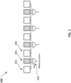
- FIG. 1A is a one-dimensional schematic perspective of an example error correction system 100 for the repetition code.
- the system 100 is a one-dimensional partition of the two-dimensional surface code.
- the system includes a one-dimensional array of physical qubits 102.
- the array of physical qubits includes data qubits, e.g., data qubits labeled 104, 108, 112, 116, and 120, interleaved with measurement qubits, e.g., measurement qubits labeled 106, 110, 114, and 118.
- the qubits may be measure-Z type qubits.
- the system includes a set of readout quantum gates, e.g., readout quantum gate 122.
- the readout gates are configured to operate on the measurement qubits, e.g., measurement qubits 106, 110, 114 and 118.
- Each readout gate may provide the state of the corresponding measurement qubit, and may be associated with a corresponding set of physical readout gate parameters.
- the system includes a set of single qubit quantum gates, e.g., single qubit gates 132 and 134.
- the single qubit quantum gates may be configured to operate on either a single data qubit or a single measurement qubit.
- the single qubit gates depicted in FIG. 1A include Pauli X gates, e.g., Pauli X gate 134, and Hadamard gates, e.g., Hadamard gate 132, however in some implementations the system may include other single qubit gates.
- the single qubit gates may include arbitrary phase shift gates or rotation gates.
- Each single qubit quantum gate may be associated with a corresponding set of physical single qubit quantum gate parameters.
- the system includes a set of controlled NOT (CNOT) gates, e.g., CNOT gate 124.
- Controlled gates may act on two or more qubits, where one or more of the qubits may act as a control for some operation.
- CNOT gates may operate on two qubits, a control qubit and a target qubit, and perform a NOT operation on the target qubit only when the control qubit is 1).
- the CNOT gates in FIG. 1A are configured to operate on pairs of neighboring measurement and data qubits, with one qubit acting as the control qubit and the other a target qubit, e.g., CNOT gate 124 operates on the pair of neighboring qubits 104 and 106.
- each data qubit operated on by a CNOT gate may be the control qubit, and each neighboring measurement qubit may be a corresponding target qubit.
- Each CNOT gate may be associated with a corresponding set of physical CNOT gate parameters.
- Each of the CNOT gates, e.g., 124, operating on the target qubits, e.g., 106, define one of a plurality of directions relative to the target qubit, for example, as shown in FIG. 1A , left and right of the target qubit.
- the CNOT quantum gates may copy bit-flip errors from the associated data qubit onto the associated measurement qubit for detection.
- a measurement qubit may be the control qubit and a neighboring data qubit may be the target qubit. The CNOT quantum gates may then copy phase flip errors from the associated measurement qubit onto the associated data qubit.
- the system includes an error correction subsystem 130 that is in data communication with the qubits 102.
- the error correction subsystem is configured to monitor the output from error detection and feed this information back to the system in order to calibrate the quantum gates.
- the error correction subsystem 130 spatially partitions the qubits 102 into one or more hardware patterns and perform quantum measurements on the measurement qubits in each hardware pattern.
- the one or more hardware patterns may be independent, such that an optimization of each hardware pattern relative to each other may be essentially independent. Partitioning qubits into one or more hardware patterns is described in more detail below with reference to FIG. 2 .
- a measurement output, or detection event may show changes in the measured pattern of states for measurement qubits, which indicates the nearby presence of errors, whether the error occurs on the associated data qubit or measurement qubit. Therefore, measurement outputs in and of themselves may not be directly correlated to errors on data qubits or measurement qubits. Correlating errors and gate parameters will be discussed in more detail below with reference to FIG. 2A - 2B .
- the error correction subsystem 130 may use the results of the performed quantum measurements to calculate relevant quantities of interest, or metrics, such as a current error rate for each measurement qubit.
- the error correction subsystem 130 may also perform additional calculations using the results of the performed quantum measurements, such as calculating average values of a determined error rate for one or more measured measurement qubits, or determining a change of error rate in time.
- the error correction subsystem 130 may include a data store, and may store the results of performed quantum measurements or additional calculations.
- the error correction subsystem uses the results of the performed measurements to optimize the parameters of the quantum gates acting on the qubits 102.
- the error correction subsystem 130 may implement a numerical optimization algorithm, such as a Nelder-Mead algorithm, to determine an appropriate adjustment of the quantum gate parameters, e.g., a minimizing set of quantum gate parameters. Once an appropriate adjustment has been determined, the error correction subsystem provides the adjustments as feedback to the qubits 102 and adjust the parameters of the quantum gates accordingly.
- a numerical optimization algorithm such as a Nelder-Mead algorithm
- FIG. 1B is a two-dimensional schematic perspective of qubits 150 in an example error correction system.
- the system may include a two-dimensional array of physical qubits 150. Again, for clarity, eighty-one qubits are depicted in FIG. 1B , however the system may include a much larger number of qubits, e.g., millions of qubits.
- the array of physical qubits includes data qubits, e.g., data qubit labeled 152, interleaved with measurement qubits, e.g., measurement qubits labeled 154, 156, 158, and 160, such that the data qubit has four neighboring measurement qubits to the top, bottom, right and left of the data qubit.
- FIG. 1B illustrates the scalability of the system 100 of FIG. 1A to higher dimensions.
- FIGS. 2A - 2B illustrate example hardware patterns used to perform quantum gate optimization.
- FIG. 2A is a one-dimensional schematic perspective of an example hardware pattern 200 in an error correction system including a one-dimensional array of physical qubits.
- the error correction system may be an error correction system including a one-dimensional array of qubits 102 as described above with reference to FIG. 1A , where gate cross hatching corresponds to which measurement qubit will detect errors from that gate.
- the hardware pattern 200 may include four hardware groupings 206, each of which contain a measurement qubit and the corresponding single qubit operations for that qubit, e.g., hardware grouping 202 contains measurement qubit 204 and the corresponding single qubit operations 208.
- the groupings within a hardware pattern may be operated independently. Errors from the single qubit operations 208 may not propagate to neighboring data qubits, and the relative detection fraction from the measurement qubit may be used to infer changes in gate parameters, as described below with reference to FIG. 6 .
- bit-flip errors may not propagate to data qubits due to the directions of the CNOT gates that are applied to the pairs of data qubits and measurement qubits. Rather, bit-flip errors may be localized to a particular measurement qubit and hence a particular hardware grouping.
- measurement qubits may have single qubit quantum gate parameters individually optimized completely in parallel as one hardware pattern 200.
- the hardware patterns that the data qubits and measurement qubits are partitioned into include one pattern including hardware groupings containing only one qubit, said one qubit being a measurement qubit.
- FIG. 2B is a one-dimensional schematic perspective of example hardware patterns 210 and 220 in an error correction system including a one-dimensional array of physical qubits.
- the error correction system may be an error correction system including a one-dimensional array of physical qubits 102 as described above with reference to FIG. 1A , where gate cross hatching corresponds to which measurement qubit will detect errors from that gate.
- the hardware pattern 210 includes multiple hardware groupings, e.g., hardware grouping 212, each of which contain one data qubit and up to two measurement qubits, along with corresponding single qubit operations for the measurement and data qubits and CNOT gates, e.g., as depicted in FIG. 2B , hardware grouping 212 contains measurement qubit 214, single qubit operation 216 and CNOT gates 218 and 219. The groupings within a hardware pattern may be operated independently.
- Errors from the single qubit operation 216 and CNOT gates 218 and 219 do not propagate outside the hardware grouping 212, and the detection event fraction of the measurement qubits within each hardware grouping may be used to infer changes in gate parameters for gates within each grouping, as described below with reference to FIGS. 7 and 8 .
- bit flip errors may be copied from data qubits through CNOT gates onto neighboring measurement qubits. Therefore, a single error on a data qubit may generate two detection events on neighboring measurement qubits and it may not be possible to optimize CNOT gate parameters on the same measurement qubit or data qubit in parallel.
- the hardware patterns e.g., 210 and 220. In general, CNOT gates fully contained in a hardware pattern may be optimized in said pattern.
- next-nearest neighboring data qubits simultaneously have their single qubit parameters optimized, they may both copy errors onto the same measurement qubit. Therefore, errors may become confused.
- every other data qubit may be optimized to avoid double mapping errors onto measurement qubits.
- Two hardware patterns 210 and 220 may be created that can simultaneously have their single qubit parameters optimized without such confusion, e.g., the optimization of both patterns 210 and 220 relative to each other are essentially independent.
- the hardware patterns that the data qubits and measurement qubits are partitioned into include patterns where the corresponding hardware groupings contain both data qubits and measurement qubits.
- the hardware patterns 200, 210 and 220 illustrated in FIGS. 2A and 2B constitute the minimum number of hardware patterns that can be used in order to perform error correction in a one-dimensional error correction system, such as that depicted in FIG. 1A .
- the below table counts the number of patterns that may be interleaved to optimize all gates in parallel. There are 3 interleaved patterns, where in each pattern one gate may be optimized in parallel. This number may be constant for a repetition code of arbitrary size, assuming that the system is performing in an ideal sense, i.e., where qubits do not have any parasitic interactions with qubits that they should not interact with.
- the illustrated patterns are a minimum set of patterns, and in some implementations more may be added as needed.
- gate parameters within each hardware grouping in a respective hardware pattern may be optimized by altering the gate parameters and minimizing the measured error rate for each hardware grouping. Furthermore, by choosing a finite number of hardware patterns, each operation required to optimize a quantum computer running error detection may be accessed. When a hardware pattern is chosen, all hardware groupings can be independently optimized in parallel, which is a O(1) scaling strategy for optimizing every single gate in an arbitrarily sized quantum computer.
- Pattern Qubit Gate 206 Measurement Single qubit ⁇ ⁇ 2 206 Measurement readout 210 Data Single qubit ⁇ ⁇ 2 210 CNOT (left) 210 CNOT (right) 220 Data Single qubit ⁇ ⁇ 2 220 CNOT (left) 220 CNOT (right)
- Optimizing gate parameters is described in more detail below with reference to FIGS. 5 -8 .
- the hardware patterns shown in the above table, and described above with reference to FIGS. 2A and 2B are representative patterns and not exhaustive. The exact patterns and respective groupings can be tailored to the system and determined by tracking error propagation in a particular circuit. For example, the hardware patterns need not be pre-computed in the system software. In some implementations the hardware patterns may be determined by varying parameters on particular gates and observing where the changes in detection events are found. By varying each of the parameters on each of the particular gates in such a manner, generated information may be processed and used to determine the hardware patterns. Such a method of determining hardware patterns may be sensitive to hardware non-idealities and increase system performance and efficiency.
- FIG. 3 is a circuit representation of a one-dimensional schematic perspective of qubits in an example error correction system.
- the output of the measurement qubit 304 may act as a multiplexer 308 with three inputs: one for the associated measurement qubit 304, and one for each neighboring data qubit 302 and 306.
- the output of one of the data or measurement boxes e.g., data boxes 302, 306 and measurement box 304
- only one of the inputs to the multiplexer may be chosen at a time. This is where the three hardware patterns 200, 210 and 220 described above with reference to FIGS. 2A - 2B originate from.
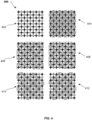
- FIG. 4 is a two-dimensional schematic perspective 400 of example hardware patterns in an error correction system.
- the same analysis described above with reference to FIGS. 2A - 2B may be applied to the surface code in order to generate the illustrated hardware patterns.
- the hardware patterns may include one hardware pattern 404 including measurement qubits.
- the remaining hardware patterns 406 - 412 may include both data qubits and measurement qubits.
- the hardware patterns 404 - 412 illustrated in FIG. 4 constitute the minimum number of hardware patterns that can be used in order to perform error correction for a system including a two-dimensional array of qubits.
- the below table counts the number of patterns that will be interleaved to optimize all gates in parallel. There are 5 interleaved patterns, where in each pattern one gate may be optimized.
- the illustrated patterns are representative and not a minimum set. Other patterns exist, and may be more complex. The number and complexity of the patterns depend on the exact details of what order quantum gates are executed across the array. As described above, by choosing such hardware patterns for the system, gate parameters within each hardware grouping in a respective hardware pattern may be optimized by altering the gate parameters and minimizing the measured error rate for each hardware grouping.
- each operation required to optimize a quantum computer running error detection may be accessed.
- a hardware pattern is chosen, all hardware groupings can be independently optimized in parallel, which is a O(1) scaling strategy for optimizing every single gate in an arbitrarily sized quantum computer.
- Optimizing gate parameters is described in more detail below with reference to FIGS. 5 -8 .
- the hardware patterns shown in the above table, and described above with reference to FIG. 4 are representative patterns and not exhaustive. The exact patterns and respective groupings can be tailored to the system and determined by tracking error propagation in a particular circuit. For example, the hardware patterns need not be pre-computed in the system software. In some implementations the hardware patterns may be determined by varying parameters on particular gates and observing where the changes in detection events are found. By varying each of the parameters on each of the particular gates in such a manner, generated information may be processed and used to determine the hardware patterns. Such a method of determining hardware patterns may be sensitive to hardware non-idealities and increase system performance and efficiency.
- the hardware patterns described in this specification are specific for a one-dimensional chain of qubits running the repetition code, but this technique may be generalizable to most error correction schemes. Any scheme that detects errors using groups of qubits of fixed maximum size, and the number of groups that any qubit belongs to does not scale with system size can utilize the hardware and methods described in this specification.
- the technique may be compatible with all topological codes including subsystem codes, and all concatenated codes by focusing on the lowest level of concatenation. This includes surface and color codes, and the Steane and Shor codes.
- the hardware and methods described in this specification may not be compatible with finite rate block codes if one wants to preserve O (1) scaling with system size. Hardware patterns and groupings can be found algorithmically by either simulating the error detection circuit, or by physically altering control parameters and determining where the detection fraction changes.
- FIGS. 2A - 2B , 3 and 4 have been described for the repetition code and surface code, the methodologies of tracing the error signatures from a gate onto physical measurements can be applied outside of the repetition and surface codes and applied to any quantum circuit and may be used as a way to provide feedback for optimization.
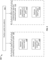
- FIG. 5 is a flow diagram of an example process 500 for performing continuous optimization of quantum gate parameters whilst error correction is running.
- the process 500 may be performed during an error correction procedure by the system 100 or 300 described above with reference to FIGS. 1A - 1B and FIG. 3 .
- the process 500 uses error detection to self-diagnose, enabling the continual optimization of control parameters whilst the system is running and hence combating system drift without interrupting a computation.
- the system spatially partitions the collection of data qubits and measurement qubits into separate hardware patterns (step 502).
- the system partitions the collection of data qubits and measurement qubits such that the errors attributable to each separate hardware pattern do not overlap with errors attributable to the other separate hardware patterns.
- the hardware patterns may include one pattern with groupings containing measurement qubits, and two or more patterns with groupings containing both data qubits and measurement qubits. The construction of partitioning a collection of data qubits and measurement qubits into separate hardware patterns is described in more detail above with reference to FIGS. 2A - 2B and FIG. 4 .
- the system enters a phase for optimizing the parameters of the quantum gates operating on the qubits in each hardware pattern with groupings containing measurement qubits (step 504).
- each of the measurement qubits in the collection of data qubits and measurement qubits may form one of the hardware patterns constructed in step 502.
- the system may optimize the parameters of the quantum gates operating on the measurement qubits in the hardware pattern 200 described above with reference to FIG. 2A .
- the system may optimize the parameters of the quantum gates operating on the measurement qubits in the hardware pattern 404 described above with reference to FIG. 4 .
- Performing optimization of the parameters of the quantum gates operating on the measurement qubits may be considered the simplest optimization phase.
- the measurement qubits may detect bit-flip errors. Since the bit-flip errors do not propagate from measurement qubits to data qubits, due to the direction of the CNOT gates that are applied to pairs of measurement and data qubits, errors are localized to a particular measurement qubit. Measurement qubits therefore have the parameters of the single qubit quantum gates operating on them individually optimized completely in parallel as one hardware pattern , as described below with reference to steps 506 and 508.
- the system performs optimization of the parameters of the readout gates operating on the measurement qubits (step 506).
- the optimization of the parameters of the readout gates operating on the measurement qubits is performed in parallel for each measurement qubit in the hardware pattern.
- An example process for optimizing the parameters of the readout gates operating on the measurement qubits is described in detail below with reference to FIG. 6 .
- the system performs optimization of the parameters of the single qubit quantum gates operating on the measurement qubits (step 508).
- the optimization of the parameters of the single qubit quantum gates operating on the measurement qubits is performed in parallel for each measurement qubit in the hardware pattern.
- An example process for optimizing the parameters of the single qubit quantum gates operating on the measurement qubits is described in detail below with reference to FIG. 6 .
- the system enters a phase for optimizing the parameters of the quantum gates operating on the qubits in each hardware pattern with groupings containing both data qubits and measurement qubits (step 510).
- the data qubits may be accompanied by measurement qubits in their respective hardware groupings constructed in step 502.
- the system may optimize the parameters of the single qubit quantum gates operating on the data qubits in the hardware patterns 210 and 220 described above with reference to FIG. 2B .
- the system may optimize the parameters of the single qubit quantum gates operating on the data qubits in the hardware patterns 406, 408, 410 and 412 described above with reference to FIG. 4 .
- Performing optimization of the parameters of single qubit quantum gates operating on the data qubits may be more complex than performing optimization of the parameters of the single qubit quantum gates operating on the measurement qubits. For example, when considering performing error correction on the repetition code, bit-flip errors may be copied from a data qubit to a neighboring measurement qubit through a CNOT gate operating on both the data qubit and the measurement qubit. Therefore, a single error on a data qubit may generate an output, or detection event, on each of its neighboring measurement qubits, as described above in with reference to FIGS. 2A and 2B .
- Data qubits may not have the parameters of the single qubit quantum gates operating on them individually optimized completely in parallel as one hardware pattern, since if next-nearest neighboring data qubits simultaneously have their single qubit gate parameters optimized, they may both copy errors onto the same measurement qubit, creating error confusion. Instead, every other data qubit may be optimized in parallel as one hardware pattern, avoiding the double mapping of errors on to measurement qubits, as described below with reference to step 512 and FIG. 6 .
- the system performs optimization of the parameters of the single qubit gates operating on the data qubits in each hardware patterns with groupings that include both data qubits and measurement qubits (step 512).
- the optimization of the parameters of the single qubit quantum gates operating on the data qubits in each hardware pattern may be performed separately for each hardware pattern.
- the optimization of the parameters of the single qubit quantum gates operating on the data qubits within each grouping in each hardware pattern may be performed in parallel for each data qubit in the hardware pattern.
- An example process for optimizing the parameters of the single qubit quantum gates operating on the data qubits is described in detail below with reference to FIG. 7 .
- Performing optimization of the parameters of the CNOT gates operating on the pairs of data qubits and measurement qubits may also be complex due to error confusion. Errors on data qubits may propagate to measurement qubits on each side of the data qubit involved. Therefore, an error on a data qubit may generate an output, or detection event, on each of its neighboring measurement qubits, as described above with reference to FIG. 2B .
- the parameters of the CNOT gates operating on the pairs of data qubits and measurement qubits therefore may not be optimized on the same data qubit or measurement qubit in parallel. This naturally restricts the hardware patterns, for example to the same as those described above with reference to step 510. In order to avoid error confusion there may be a simple rule: only CNOT gates fully contained in a hardware pattern may be optimized in said pattern.
- the system performs optimization of the parameters of the CNOT gates operating on the pairs of data qubits and measurement qubits in each hardware grouping that includes both data qubits and measurement qubits in the hardware pattern (step 514).
- the optimization of the parameters of the CNOT gates operating on the pairs of data qubits and measurement qubits in the hardware pattern may be performed separately for each hardware pattern.
- the system selects CNOT gates that define a same direction within each hardware pattern and optimizes the parameters of the CNOT gates that define the same direction in parallel for each data qubit in the hardware pattern.
- the system may first select the set of CNOT gates that are left of the data qubits and optimize the selected CNOT gate parameters in parallel, then select the set of CNOT gates that are right of the data qubits and optimize the selected CNOT gate parameters in parallel.
- An example process for optimizing the parameters of the CNOT gates operating on the data qubits and measurement qubits is described in detail below with reference to FIG. 8 .
- the flow diagram of the example process 500 for performing continuous optimization of quantum gate parameters whilst error correction is running has been described with reference to the steps 504 - 514. However, it may not be necessary that the operations of steps 504 - 514 are performed sequentially in the presented order.
- the steps may be performed in different sequences, and may be performed more than once, i.e., as required, before the next step in the sequence is performed
- the system may first enter a phase for optimizing the parameters of the quantum gates operating on the qubits in each hardware pattern containing both data qubits and measurement qubits before entering the phase for optimizing the parameters of the quantum gates operating on the qubits in each hardware pattern containing measurement qubits.
- the system may first perform the optimization step 508 before performing the optimization step 506.
- steps 506, 508, 512 and 514 i.e., by cycling between hardware patterns, system drift on every parameter of every gate for every qubit may be combatted while the system is running.
- FIG. 6 is a flow diagram of an example process 600 for optimizing the parameters of readout gates or single qubit quantum gates operating on measurement qubits.
- the process 600 may be performed by the system 100 or 300 described above with reference to FIGS. 1A - 1B and FIG. 3 for optimizing the parameters of readout quantum gates, as described above in step 506 of FIG. 5 , or for optimizing the parameters of single qubit quantum gates, as described above in step 508 of FIG. 5 .
- each of the measurement qubits in the collection of data qubits and measurement qubits described in FIGS. 1A - 1B and FIG. 3 form one of the hardware patterns constructed in step 502 with reference to FIG. 5 above.
- the system may optimize the parameters of the readout quantum gates or single qubit quantum gates operating on the measurement qubits in the hardware pattern 202 described above with reference to FIG. 2A .
- the system may optimize the parameters of the quantum gates operating on the measurement qubits in the hardware pattern 404 described above with reference to FIG. 4 .
- the process 600 may be performed in parallel for each measurement qubit in the corresponding hardware pattern.
- the process 600 may be a continuously repeated process that uses closed loop feedback to optimize the parameters of readout gates or single qubit quantum gates operating on measurement qubits.
- the system defines a corresponding metric for error minimization as a determined error rate (step 602).
- the metric for error minimization may be the fraction of detection events for that qubit.
- the metric for error minimization is the average fraction of detection events taken over all measurement qubits.
- the system measures the measurement qubits to determine a current error rate (step 604).
- the system stores the determined error rate (step 606).
- the system stores the determined error rates for each repetition of the process 600 such that the change in error rate may be monitored over time, and correlated with changes made to the quantum gate parameters.
- the system calculates a change in the error rate between the determined current error rate and the stored error rate from the previous repetition (step 608).
- Measurement outputs, or detection events, and changes in the measured patterns of states for measurement qubits may indicate the nearby presence of errors, whether on data qubits or measurement qubits.
- detection events themselves may not be directly correlated to errors on measurement qubits or data qubits. Therefore, in order to correlate a change in error with a change in gate parameters, the change in the localized detection event fraction, i.e., the error rate, may be compared with the change in gate parameters.
- the system adjusts the readout gate parameters, or the single qubit quantum gate parameters, based on the calculated change in error rate (step 610).
- the system may apply a numerical optimization algorithm, such as a Nelder-Mead method, to determine the adjustments to be made to the readout gate parameters or single qubit quantum gate parameters, based on the change in error rate calculated in step 608.
- the system may continuously repeat the steps 602 - 610 described above.
- it may be possible to distinguish between measure-X and measure-Y qubits in order to obtain more information as to the physical processes associated with the gate errors, and this information may be fed back to the system in order to optimize the quantum gates more efficiently.
- FIG. 7 is a flow diagram of an example process 700 for optimizing the parameters of single qubit quantum gates operating on data qubits.
- the process 700 may be performed by the system 100 or 300 described above with reference to FIGS. 1A - 1B and FIG. 3 for optimizing the parameters of single qubit quantum gates, as described above in step 512 of FIG. 5 .
- the process may be performed for each hardware pattern with groupings including both data qubits and measurement qubits constructed in step 502 with reference to FIG. 5 above.
- the system may optimize the parameters of the single qubit quantum gates operating on the data qubits in the hardware patterns 210 and 220 described above with reference to FIG. 2B .
- the system may optimize the parameters of the quantum gates operating on the measurement qubits in the hardware patterns 406, 408, 410 and 412 described above with reference to FIG. 4 .
- the process 700 may be performed in parallel for each data qubit in the corresponding hardware pattern.
- the process 700 may be a continuously repeated process that uses closed loop feedback to optimize the parameters of the single qubit quantum gates operating on the data qubits.
- the system defines a corresponding metric for error minimization as a determined error rate (step 702).
- a corresponding metric for error minimization may be minimized.
- the metric for error minimization may be the average fraction of detection events taken over all measurement qubits.
- the system measures the corresponding neighboring measurement qubits to determine a current error rate (step 704).
- the system may measure at least two corresponding measurement qubits.
- the system may measure at least four corresponding measurement qubits.
- the system stores the determined error rates (step 706).
- the system stores the determined error rates for each repetition of the process 700 such that the change in error rate may be monitored over time, and correlated with changes made to the quantum gate parameters.
- the system calculates a change in the error rate between the determined current error rate and the stored error rate from the previous repetition (step 708).
- Measurement outputs, or detection events, and changes in the measured patterns of states for measurement qubits may indicate the nearby presence of errors, whether on data qubits or measurement qubits.
- detection events themselves may not be directly correlated to errors on measurement qubits or data qubits. Therefore, in order to correlate a change in error with a change in gate parameters, the change in the localized detection event fraction, i.e., the error rate, may be compared with the change in gate parameters.
- the system adjusts the single qubit gate parameters based on the calculated change in error rate (step 710).
- the system may apply a numerical optimization algorithm, such as a Nelder-Mead method, to determine the adjustments to be made to the single qubit quantum gate parameters, based on the change in error rate calculated in step 708.
- the system may continuously repeat the steps 702 - 710 described above.
- it may be possible to distinguish between measure-X and measure-Y qubits in order to obtain more information as to the physical processes associated with the gate errors, and this information may be fed back to the system in order to optimize the quantum gates more efficiently.
- FIG. 8 is a flow diagram of an example process 800 for optimizing the parameters of CNOT gates operating on pairs of data qubits and measurement qubits.
- the process 800 may be performed by the system 100 or 300, described above with reference to FIGS. 1A - 1B and FIG. 3 , for optimizing the parameters of CNOT gates, as described above in step 514 of FIG. 5 .
- the process may be performed for each hardware pattern with groupings including both data qubits and measurement qubits constructed in step 502 with reference to FIG. 5 above.
- the system may optimize the parameters of the CNOT gates operating on the pairs of data qubits and measurement qubits in the hardware patterns 210 and 220 described above with reference to FIG. 2B .
- the system may optimize the parameters of the quantum gates operating on the measurement qubits in the hardware patterns 406 - 412 described above with reference to FIG. 4 .
- the process 800 may be performed in parallel for each CNOT gate fully contained in the corresponding hardware pattern that defines a same direction in relation to the data qubit that the CNOT gate operates on.
- the process 800 may be a continuously repeated process that uses closed loop feedback to optimize the parameters of the CNOT gates.
- the system defines a corresponding metric for error minimization as a determined error rate (step 802).
- a corresponding metric for error minimization may be minimized.
- the metric for error minimization may be the average fraction of detection events taken over all measurement qubits.
- the system measures the corresponding neighboring measurement qubits to determine a current error rate (step 804).
- the system may measure at least two corresponding measurement qubits.
- the system may measure at least four corresponding measurement qubits.
- the system stores the determined error rates (step 806).
- the system stores the determined error rates for each repetition of the process 800 such that the change in error rate may be monitored over time, and correlated with changes made to the quantum gate parameters.
- the system calculates a change in the error rate between the determined current error rate and the stored error rate from the previous repetition (step 808).
- Measurement outputs, or detection events, and changes in the measured patterns of states for measurement qubits may indicate the nearby presence of errors, whether on data qubits or measurement qubits.
- detection events themselves may not be directly correlated to errors on measurement qubits or data qubits. Therefore, in order to correlate a change in error with a change in gate parameters, the change in the localized detection event fraction, i.e., the error rate, may be compared with the change in gate parameters.
- the system adjusts the CNOT gate parameters based on the calculated change in error rate (step 810).
- the system may apply a numerical optimization algorithm, such as a Nelder-Mead method, to determine the adjustments to be made to the CNOT quantum gate parameters, based on the change in error rate calculated in step 808.
- the system may continuously repeat the steps 802 - 810 described above.
- it may be possible to distinguish between measure-X and measure-Y qubits in order to obtain more information as to the physical processes associated with the gate errors, and this information may be fed back to the system in order to optimize the quantum gates more efficiently.
- Implementations of the digital and/or quantum subject matter and the digital functional operations and quantum operations described in this specification can be implemented in digital electronic circuitry, suitable quantum circuitry or, more generally, quantum computational systems, in tangibly-embodied digital and/or quantum computer software or firmware, in digital and/or quantum computer hardware, including the structures disclosed in this specification and their structural equivalents, or in combinations of one or more of them.
- quantum computational systems may include, but is not limited to, quantum computers, quantum information processing systems, quantum cryptography systems.
- Implementations of the digital and/or quantum subject matter described in this specification can be implemented as one or more digital and/or quantum computer programs, i.e., one or more modules of digital and/or quantum computer program instructions encoded on a tangible non-transitory storage medium for execution by, or to control the operation of, data processing apparatus.
- the digital and/or quantum computer storage medium can be a machine-readable storage device, a machine-readable storage substrate, a random or serial access memory device, one or more qubits, or a combination of one or more of them.
- the program instructions can be encoded on an artificially-generated propagated signal that is capable of encoding digital and/or quantum information, e.g., a machine-generated electrical, optical, or electromagnetic signal, that is generated to encode digital and/or quantum information for transmission to suitable receiver apparatus for execution by a data processing apparatus.
- digital and/or quantum information e.g., a machine-generated electrical, optical, or electromagnetic signal
- quantum information and quantum data refer to information or data that is carried by, held or stored in quantum systems, where the smallest non-trivial system is a qubit, i.e., a system that defines the unit of quantum information.
- qubit encompasses all quantum systems that may be suitably approximated as a two-level system in the corresponding context.
- Such quantum systems may include multi-level systems, e.g., with two or more levels.
- such systems can include atoms, electrons, photons, ions or superconducting qubits.
- the computational basis states are identified with the ground and first excited states, however it is understood that other setups where the computational states are identified with higher level excited states are possible.
- data processing apparatus refers to digital and/or quantum data processing hardware and encompasses all kinds of apparatus, devices, and machines for processing digital and/or quantum data, including by way of example a programmable digital processor, a programmable quantum processor, a digital computer, a quantum computer, multiple digital and quantum processors or computers, and combinations thereof.
- the apparatus can also be, or further include, special purpose logic circuitry, e.g., an FPGA (field programmable gate array), an ASIC (application-specific integrated circuit), or a quantum simulator, i.e., a quantum data processing apparatus that is designed to simulate or produce information about a specific quantum system.
- a quantum simulator is a special purpose quantum computer that does not have the capability to perform universal quantum computation.
- the apparatus can optionally include, in addition to hardware, code that creates an execution environment for digital and/or quantum computer programs, e.g., code that constitutes processor firmware, a protocol stack, a database management system, an operating system, or a combination of one or more of them.
- code that creates an execution environment for digital and/or quantum computer programs e.g., code that constitutes processor firmware, a protocol stack, a database management system, an operating system, or a combination of one or more of them.
- a digital computer program which may also be referred to or described as a program, software, a software application, a module, a software module, a script, or code, can be written in any form of programming language, including compiled or interpreted languages, or declarative or procedural languages, and it can be deployed in any form, including as a stand-alone program or as a module, component, subroutine, or other unit suitable for use in a digital computing environment.
- a quantum computer program which may also be referred to or described as a program, software, a software application, a module, a software module, a script, or code, can be written in any form of programming language, including compiled or interpreted languages, or declarative or procedural languages, and translated into a suitable quantum programming language, or can be written in a quantum programming language, e.g., QCL or Quipper.
- a digital and/or quantum computer program may, but need not, correspond to a file in a file system.
- a program can be stored in a portion of a file that holds other programs or data, e.g., one or more scripts stored in a markup language document, in a single file dedicated to the program in question, or in multiple coordinated files, e.g., files that store one or more modules, sub-programs, or portions of code.
- a digital and/or quantum computer program can be deployed to be executed on one digital or one quantum computer or on multiple digital and/or quantum computers that are located at one site or distributed across multiple sites and interconnected by a digital and/or quantum data communication network.
- a quantum data communication network is understood to be a network that may transmit quantum data using quantum systems, e.g. qubits. Generally, a digital data communication network cannot transmit quantum data, however a quantum data communication network may transmit both quantum data and digital data.
- the processes and logic flows described in this specification can be performed by one or more programmable digital and/or quantum computers, operating with one or more digital and/or quantum processors, as appropriate, executing one or more digital and/or quantum computer programs to perform functions by operating on input digital and quantum data and generating output.
- the processes and logic flows can also be performed by, and apparatus can also be implemented as, special purpose logic circuitry, e.g., an FPGA or an ASIC, or a quantum simulator, or by a combination of special purpose logic circuitry or quantum simulators and one or more programmed digital and/or quantum computers.
- a system of one or more digital and/or quantum computers to be "configured to" perform particular operations or actions means that the system has installed on it software, firmware, hardware, or a combination of them that in operation cause the system to perform the operations or actions.
- one or more digital and/or quantum computer programs to be configured to perform particular operations or actions means that the one or more programs include instructions that, when executed by digital and/or quantum data processing apparatus, cause the apparatus to perform the operations or actions.
- a quantum computer may receive instructions from a digital computer that, when executed by the quantum computing apparatus, cause the apparatus to perform the operations or actions.
- Digital and/or quantum computers suitable for the execution of a digital and/or quantum computer program can be based on general or special purpose digital and/or quantum processors or both, or any other kind of central digital and/or quantum processing unit.
- a central digital and/or quantum processing unit will receive instructions and digital and/or quantum data from a read-only memory, a random access memory, or quantum systems suitable for transmitting quantum data, e.g. photons, or combinations thereof .
- the essential elements of a digital and/or quantum computer are a central processing unit for performing or executing instructions and one or more memory devices for storing instructions and digital and/or quantum data.
- the central processing unit and the memory can be supplemented by, or incorporated in, special purpose logic circuitry or quantum simulators.
- a digital and/or quantum computer will also include, or be operatively coupled to receive digital and/or quantum data from or transfer digital and/or quantum data to, or both, one or more mass storage devices for storing digital and/or quantum data, e.g., magnetic, magneto-optical disks, optical disks, or quantum systems suitable for storing quantum information.
- mass storage devices for storing digital and/or quantum data, e.g., magnetic, magneto-optical disks, optical disks, or quantum systems suitable for storing quantum information.
- a digital and/or quantum computer need not have such devices.
- Digital and/or quantum computer-readable media suitable for storing digital and/or quantum computer program instructions and digital and/or quantum data include all forms of non-volatile digital and/or quantum memory, media and memory devices, including by way of example semiconductor memory devices, e.g., EPROM, EEPROM, and flash memory devices; magnetic disks, e.g., internal hard disks or removable disks; magneto-optical disks; CD-ROM and DVD-ROM disks; and quantum systems, e.g., trapped atoms or electrons.
- semiconductor memory devices e.g., EPROM, EEPROM, and flash memory devices
- magnetic disks e.g., internal hard disks or removable disks
- magneto-optical disks CD-ROM and DVD-ROM disks
- quantum systems e.g., trapped atoms or electrons.
- quantum memories are devices that can store quantum data for a long time with high fidelity and efficiency, e.g., light-matter interfaces where light is used for transmission and matter for storing and preserving the quantum features of quantum data such as superposition or quantum coherence.
- Control of the various systems described in this specification, or portions of them, can be implemented in a digital and/or quantum computer program product that includes instructions that are stored on one or more non-transitory machine-readable storage media, and that are executable on one or more digital and/or quantum processing devices.
- the systems described in this specification, or portions of them, can each be implemented as an apparatus, method, or system that may include one or more digital and/or quantum processing devices and memory to store executable instructions to perform the operations described in this specification.
Landscapes
- Engineering & Computer Science (AREA)
- Theoretical Computer Science (AREA)
- Physics & Mathematics (AREA)
- General Physics & Mathematics (AREA)
- General Engineering & Computer Science (AREA)
- Mathematical Physics (AREA)
- Computing Systems (AREA)
- Software Systems (AREA)
- Evolutionary Computation (AREA)
- Computational Mathematics (AREA)
- Artificial Intelligence (AREA)
- Mathematical Analysis (AREA)
- Mathematical Optimization (AREA)
- Pure & Applied Mathematics (AREA)
- Condensed Matter Physics & Semiconductors (AREA)
- Data Mining & Analysis (AREA)
- Quality & Reliability (AREA)
- Error Detection And Correction (AREA)
- Testing Or Measuring Of Semiconductors Or The Like (AREA)
- Tests Of Electronic Circuits (AREA)
- Other Investigation Or Analysis Of Materials By Electrical Means (AREA)
- Pharmaceuticals Containing Other Organic And Inorganic Compounds (AREA)
- Detection And Prevention Of Errors In Transmission (AREA)
Claims (13)
- Quantenrechensystem, Folgendes umfassend:eine Anordnung von physischen Qubits, wobei die Anordnung von physischen Qubits eine eindimensionale Anordnung von physischen Qubits oder eine zweidimensionale Anordnung von physischen Qubits ist, wobei die Anordnung von physischen Qubits eine Vielzahl von Daten-Qubits umfasst, undeine Vielzahl von Messungs-Qubits, die die Daten-Qubits derart verschachteln, dass jedes Daten-Qubit ein oder mehrere benachbarte Messungs-Qubits aufweist;eine Vielzahl von Auslese-Quantengattern, wobei jedes Auslese-Quantengatter dazu konfiguriert ist, an einem Messungs-Qubit aus der Vielzahl von Messungs-Qubits zu arbeiten;eine Vielzahl von Einzel-Qubit-Quantengattern, wobei jedes Einzel-Qubit-Quantengatter dazu konfiguriert ist, an einem Daten-Qubit aus der Vielzahl von Daten-Qubits oder einem Messungs-Qubit aus der Vielzahl von Messungs-Qubits zu arbeiten;eine Vielzahl von CNOT-Quantengattern, wobei jedes CNOT-Quantengatter dazu konfiguriert ist, an einem Daten-Qubit aus der Vielzahl von Daten-Qubits und an einem benachbarten Messungs-Qubit aus der Vielzahl von Messungs-Qubits zu arbeiten, wobei eines dieser zwei Qubits als Steuer-Qubit und das andere als Ziel-Qubit fungiert,und jedes CNOT-Quantengatter eine von einer Vielzahl von Richtungen relativ zu dem Ziel-Qubit definiert, unddas Quantenrechensystem ferner ein Fehlerkorrektur-Subsystem in Datenkommunikation mit den Messungs-Qubits umfasst, wobei das Fehlerkorrektur-Subsystem dazu konfiguriert ist, Fehlererkennungsinformationen zu empfangen und eine entsprechende Fehlerkorrektur durchzuführen, um Parameter der Auslese-Quantengatter, der Einzel-Quantengatter und der CNOT-Quantengatter zu kalibrieren, und das basierend auf den Fehlererkennungsinformationen und parallel zu der Fehlerkorrektur zu Folgendem konfiguriert ist:Unterteilen der Daten-Qubits und der Messungs-Qubits in eine Vielzahl von Mustern, wobei jedes Muster eine Vielzahl von nicht überlappenden Gruppierungen von Qubits und ihren entsprechenden Gattern umfasst, wobei die Gruppierungen unabhängig voneinander betrieben werden können, wobei sich Fehler von den Gattern innerhalb jeder Gruppierung nicht außerhalb der Gruppierung ausbreiten, wobei die Vielzahl von Mustern Folgendes beinhaltet: ein erstes Muster, in dem jede Gruppierung nur ein Qubit beinhaltet, wobei das eine Qubit ein Messungs-Qubit ist; undzweite Muster, in denen jede Gruppierung ein Daten-Qubit und seine benachbarten Messungs-Qubits beinhaltet;für das erste Muster:gleichzeitiges Optimieren der Parameter von Auslese-Quantengattern, die an den Messungs-Qubits der Gruppierungen des ersten Musters arbeiten; undgleichzeitiges Optimieren der Parameter von Einzel-Qubit-Quantengattern, die an den Messungs-Qubits der Gruppierungen des ersten Musters arbeiten;für jedes zweite Muster:gleichzeitiges Optimieren der Parameter von Einzel-Qubit-Quantengattern, die an den Daten-Qubits der Gruppierungen dieses zweiten Musters arbeiten; undAuswählen von Sätzen der CNOT-Quantengatter, die an den Daten-Qubits und Messungs-Qubits der Gruppierungen dieses zweiten Musters arbeiten, Definieren einer gleichen Richtung innerhalb dieses zweiten Musters und gleichzeitiges Optimieren der Parameter für die CNOT-Quantengatter dieses ausgewählten Satzes für jeden ausgewählten Satz.
- Quantenrechensystem nach Anspruch 1, wobei die Vielzahl von Daten-Qubits und Messungs-Qubits derart verschachtelt ist, dass die Vielzahl von Daten-Qubits und Messungs-Qubits eine eindimensionale Kette von Qubits definiert und die Vielzahl von Richtungen eine erste Richtung und eine der ersten Richtung entgegengesetzte zweite Richtung umfasst.
- Quantenrechensystem nach Anspruch 1, wobei die Vielzahl von Einzel-Qubit-Quantengattern Phasenverschiebungsgatter oder Rotationsgatter sind.
- Quantenrechensystem nach Anspruch 1, wobei das Fehlerkorrektur-Subsystem zum gleichzeitigen Optimieren der Parameter von Auslese-Quantengattern, die an den Messungs-Qubits der Gruppierungen des ersten Musters arbeiten, dazu konfiguriert ist, einen wiederholten Prozess unter Verwendung eines geschlossenen Regelkreises durchzuführen, wobei das Fehlerkorrektur-Subsystem bei jeder Wiederholung zu Folgendem konfiguriert ist:Definieren einer entsprechenden Metrik zur Minimierung als bestimmte Fehlerrate;Messen des Messungs-Qubits zum Bestimmen einer aktuellen Fehlerrate;Speichern der bestimmten aktuellen Fehlerrate;Berechnen einer Änderung der Fehlerrate zwischen der aktuellen Fehlerrate und der gespeicherten Fehlerrate aus der vorherigen Wiederholung; undEinstellen der Auslesegatterparameter basierend auf der berechneten Änderung der Fehlerrate.
- Quantenrechensystem nach Anspruch 4, wobei das Fehlerkorrektur-Subsystem zum Anpassen der Auslesegatterparameter basierend auf der berechneten Änderung der Fehlerrate konfiguriert ist, einen numerischen Optimierungsalgorithmus anzuwenden.
- Quantenrechensystem nach Anspruch 1, wobei das Fehlerkorrektur-Subsystem zum gleichzeitigen Optimieren der Parameter von Einzel-Qubit-Quantengattern, die an den Messungs-Qubits der Gruppierungen des ersten Musters oder an den Daten-Qubits der Gruppierungen eines zweiten Musters der zweiten Muster arbeiten, dazu konfiguriert ist, einen wiederholten Prozess unter Verwendung eines geschlossenen Regelkreises durchzuführen, wobei das Fehlerkorrektur-Subsystem bei jeder Wiederholung für jedes Messungs-Qubit oder Daten-Qubit gleichzeitig zu Folgendem konfiguriert ist:Definieren einer entsprechenden Metrik zur Minimierung als bestimmte Fehlerrate;Messen des Messungs-Qubits oder der dem Daten-Qubit entsprechenden Messungs-Qubits zum Bestimmen einer Fehlerrate;Speichern der bestimmten aktuellen Fehlerrate;Berechnen einer Änderung der Fehlerrate zwischen der aktuellen Fehlerrate und der gespeicherten Fehlerrate aus der vorherigen Wiederholung; undEinstellen der Einzel-Qubit-Gatterparameter basierend auf der berechneten Änderung der Fehlerrate,wobei das Fehlerkorrektur-Subsystem zum Einstellen der Einzel-Qubit-Gatterparameter basierend auf der berechneten Änderung der Fehlerrate bevorzugt dazu konfiguriert ist, einen numerischen Optimierungsalgorithmus anzuwenden.
- Quantenrechensystem nach Anspruch 1, wobei das Fehlerkorrektur-Subsystem zum Auswählen von Sätzen von CNOT-Gattern, die eine gleiche Richtung definieren, und zum gleichzeitigen Optimieren der Parameter für die ausgewählten CNOT-Gatter für jeden ausgewählten Satz von CNOT-Gattern zu Folgendem konfiguriert ist:
gleichzeitig für jedes Daten-Qubit in dem ausgewählten Satz:Definieren einer entsprechenden Metrik zur Minimierung als bestimmte Fehlerrate;Messen der entsprechenden Messungs-Qubits zum Bestimmen einer Fehlerrate;Speichern der bestimmten aktuellen Fehlerrate;Berechnen einer Änderung der Fehlerrate zwischen der aktuellen Fehlerrate und der gespeicherten Fehlerrate aus der vorherigen Wiederholung; undEinstellen der CNOT-Gatterparameter basierend auf der berechneten Änderung der Fehlerrate, wobei das Fehlerkorrektur-Subsystem zum Einstellen der CNOT-Gatterparameter basierend auf der berechneten Änderung der Fehlerrate bevorzugt dazu konfiguriert ist, einen numerischen Optimierungsalgorithmus anzuwenden. - Verfahren, umfassend:(i) Zugreifen auf ein Quantenrechensystem, das Folgendes umfasst:eine Anordnung von physischen Qubits, wobei die Anordnung von physischen Qubits eine eindimensionale Anordnung von physischen Qubits oder eine zweidimensionale Anordnung von physischen Qubits ist, wobei die Anordnung von physischen Qubits eine Vielzahl von Daten-Qubits umfasst, undeine Vielzahl von Messungs-Qubits, die die Daten-Qubits derart verschachteln, dass jedes Daten-Qubit ein oder mehrere benachbarte Messungs-Qubits aufweist;eine Vielzahl von Auslese-Quantengattern, wobei jedes Auslese-Quantengatter dazu konfiguriert ist, an einem Messungs-Qubit aus der Vielzahl von Messungs-Qubits zu arbeiten;eine Vielzahl von Einzel-Qubit-Quantengattern, wobei jedes Einzel-Qubit-Quantengatter dazu konfiguriert ist, an einem Daten-Qubit aus der Vielzahl von Daten-Qubits oder einem Messungs-Qubit aus der Vielzahl von Messungs-Qubits zu arbeiten;eine Vielzahl von CNOT-Quantengattern, wobei jedes CNOT-Quantengatter dazu konfiguriert ist, an einem Daten-Qubit aus der Vielzahl von Daten-Qubits und an einem benachbarten Messungs-Qubit aus der Vielzahl von Messungs-Qubits zu arbeiten, wobei eines dieser zwei Qubits als Steuer-Qubit und das andere als Ziel-Qubit fungiert, und jedes CNOT-Quantengatter eine von einer Vielzahl von Richtungen relativ zu dem Ziel-Qubit definiert; wobei das Quantenrechnungssystem ferner ein Fehlerkorrektur-Subsystem in Datenkommunikation mit den Messungs-Qubits umfasst, wobei das Fehlerkorrektur-Subsystem dazu konfiguriert ist, Fehlererkennungsinformationen zu empfangen und eine entsprechende Fehlerkorrektur durchzuführen, um Parameter der Auslese-Quantengatter, der Einzel-Quantengatter und der CNOT-Quantengatter zu kalibrieren;Durchführen der folgenden Schritte unter Verwendung des Fehlerkorrektur-Subsystems basierend auf den Fehlererkennungsinformationen und gleichzeitig mit der Fehlerkorrektur:(ii) Unterteilen der Daten-Qubits und der Messungs-Qubits in eine Vielzahl von Mustern, wobei jedes Muster eine Vielzahl von nicht überlappenden Gruppierungen von Qubits und ihren entsprechenden Gattern umfasst, wobei die Gruppierungen unabhängig voneinander betrieben werden können, wobei sich Fehler von den Gattern innerhalb jeder Gruppierung nicht außerhalb der Gruppierung ausbreiten, wobei die Vielzahl von Mustern Folgendes beinhaltet: ein erstes Muster, in dem jede Gruppierung nur ein Qubit beinhaltet, wobei das eine Qubit ein Messungs-Qubit ist; und zweite Muster, in denen jede Gruppierung ein Daten-Qubit und seine benachbarten Messungs-Qubits beinhaltet;(iii) für das erste Muster:gleichzeitiges Optimieren der Parameter von Auslese-Quantengattern, die an den Messungs-Qubits der Gruppierungen des ersten Musters arbeiten; undgleichzeitiges Optimieren der Parameter von Einzel-Qubit-Quantengattern, die an den Messungs-Qubits der Gruppierungen des ersten Musters arbeiten;für jedes zweite Muster:gleichzeitiges Optimieren der Parameter von Einzel-Qubit-Quantengattern, die an den Daten-Qubits der Gruppierungen dieses zweiten Musters arbeiten; undAuswählen von Sätzen der CNOT-Quantengatter, die an den Daten-Qubits und Messungs-Qubits der Gruppierungen dieses zweiten Musters arbeiten, Definieren einer gleichen Richtung innerhalb dieses zweiten Musters und gleichzeitiges Optimieren der Parameter für die CNOT-Quantengatter dieses ausgewählten Satzes für jeden ausgewählten Satz.
- Verfahren nach Anspruch 8, wobei die Vielzahl von Daten-Qubits und Messungs-Qubits derart verschachtelt ist, dass die Vielzahl von Daten-Qubits und Messungs-Qubits eine eindimensionale Kette von Qubits definiert und die Vielzahl von Richtungen eine erste Richtung und eine der ersten Richtung entgegengesetzte zweite Richtung umfasst.
- Verfahren nach Anspruch 8, wobei die Vielzahl von Einzel-Qubit-Quantengattern Phasenverschiebungsgatter oder Rotationsgatter sind.
- Verfahren nach Anspruch 8, wobei das gleichzeitige Optimieren der Parameter von Auslesequantengattern, die an den Messungs-Qubits der Gruppierungen des ersten Musters arbeiten, ein wiederholter Prozess unter Verwendung eines geschlossenen Regelkreises ist, wobei jede Wiederholung für jedes Messungs-Qubit gleichzeitig Folgendes umfasst:Definieren einer entsprechenden Metrik zur Minimierung als bestimmte Fehlerrate;Messen des Messungs-Qubits zum Bestimmen einer aktuellen Fehlerrate;Speichern der bestimmten aktuellen Fehlerrate;Berechnen einer Änderung der Fehlerrate zwischen der aktuellen Fehlerrate und der gespeicherten Fehlerrate aus der vorherigen Wiederholung; undEinstellen der Auslesegatterparameter basierend auf der berechneten Änderung der Fehlerrate, wobei das Einstellen der Einzel-Qubit-Gatterparameter basierend auf der berechneten Änderung der Fehlerrate bevorzugt das Anwenden eines numerischen Optimierungsalgorithmus umfasst.
- Verfahren nach Anspruch 8, wobei das gleichzeitige Optimieren der Parameter von Einzel-Qubit-Quantengattern, die an den Messungs-Qubits der Gruppierungen des ersten Musters oder an den Daten-Qubits der Gruppierungen eines zweiten Musters der zweiten Muster arbeiten, ein wiederholter Prozess unter Verwendung eines geschlossenen Regelkreises ist, wobei jede Wiederholung für jedes Messungs-Qubit oder Daten-Qubit gleichzeitig Folgendes umfasst:Definieren einer entsprechenden Metrik zur Minimierung als bestimmte Fehlerrate;Messen des Messungs-Qubits oder der dem Daten-Qubit entsprechenden Messungs-Qubits zum Bestimmen einer Fehlerrate;Speichern der bestimmten aktuellen Fehlerrate;Berechnen einer Änderung der Fehlerrate zwischen der aktuellen Fehlerrate und der gespeicherten Fehlerrate aus der vorherigen Wiederholung; undEinstellen der Einzel-Qubit-Gatterparameter basierend auf der berechneten Änderung der Fehlerrate, wobei das Einstellen der Einzel-Qubit-Gatterparameter basierend auf der berechneten Änderung der Fehlerrate bevorzugt das Anwenden eines numerischen Optimierungsalgorithmus umfasst.
- Verfahren nach Anspruch 8, wobei das Auswählen von Sätzen von CNOT-Gattern, die eine gleiche Richtung definieren und das gleichzeitige Optimieren der Parameter für die ausgewählten CNOT-Gatter für jeden ausgewählten Satz von CNOT-Gattern Folgendes umfasst:
gleichzeitig für jedes Daten-Qubit in dem ausgewählten Satz:Definieren einer entsprechenden Metrik zur Minimierung als bestimmte Fehlerrate;Messen der entsprechenden Messungs-Qubits zum Bestimmen einer Fehlerrate;Speichern der bestimmten aktuellen Fehlerrate;Berechnen einer Änderung der Fehlerrate zwischen der aktuellen Fehlerrate und der gespeicherten Fehlerrate aus der vorherigen Wiederholung; undEinstellen der CNOT-Gatterparameter basierend auf der berechneten Änderung der Fehlerrate, wobei das Einstellen der Einzel-Qubit-Gatterparameter basierend auf der berechneten Änderung der Fehlerrate bevorzugt das Anwenden eines numerischen Optimierungsalgorithmus umfasst.
Applications Claiming Priority (1)
| Application Number | Priority Date | Filing Date | Title |
|---|---|---|---|
| PCT/US2015/059481 WO2017078734A1 (en) | 2015-11-06 | 2015-11-06 | In-situ quantum error correction |
Publications (2)
| Publication Number | Publication Date |
|---|---|
| EP3371752A1 EP3371752A1 (de) | 2018-09-12 |
| EP3371752B1 true EP3371752B1 (de) | 2025-04-16 |
Family
ID=54548297
Family Applications (1)
| Application Number | Title | Priority Date | Filing Date |
|---|---|---|---|
| EP15795313.4A Active EP3371752B1 (de) | 2015-11-06 | 2015-11-06 | In-situ-quantenfehlerkorrektur |
Country Status (8)
| Country | Link |
|---|---|
| US (4) | US10692009B2 (de) |
| EP (1) | EP3371752B1 (de) |
| JP (1) | JP6641494B2 (de) |
| KR (1) | KR102110488B1 (de) |
| CN (2) | CN108885720B (de) |
| AU (4) | AU2015413915B2 (de) |
| SG (1) | SG11201803790QA (de) |
| WO (1) | WO2017078734A1 (de) |
Families Citing this family (50)
| Publication number | Priority date | Publication date | Assignee | Title |
|---|---|---|---|---|
| EP3371752B1 (de) | 2015-11-06 | 2025-04-16 | Google LLC | In-situ-quantenfehlerkorrektur |
| EP4482035A3 (de) | 2017-03-10 | 2025-03-19 | Rigetti & Co, LLC | Durchführung eines kalibrierungsprozesses in einem quantendatenverarbeitungssystem |
| KR102582515B1 (ko) * | 2017-06-26 | 2023-09-26 | 구글 엘엘씨 | 양자 컴퓨팅 장치의 비선형 교정 |
| CA3072403C (en) | 2017-08-09 | 2023-03-21 | Google Llc | Reducing parasitic interactions in a qubit grid for surface code error correction |
| AU2017426939C1 (en) | 2017-08-09 | 2021-10-14 | Google Llc | Frequency pattern for reducing parasitic interactions in a qubit grid |
| WO2019032104A1 (en) | 2017-08-09 | 2019-02-14 | Google Llc | REDUCTION OF PARASITE INTERACTIONS IN A QUANTIC BIT GRID |
| US11875222B1 (en) * | 2017-09-18 | 2024-01-16 | Rigetti & Co, Llc | Maintaining calibration in a quantum computing system |
| US10885678B2 (en) * | 2017-09-29 | 2021-01-05 | International Business Machines Corporation | Facilitating quantum tomography |
| AU2017443044C1 (en) * | 2017-12-15 | 2021-07-22 | Google Llc | Refining qubit calibration models using supervised learning |
| US11361241B2 (en) | 2018-03-02 | 2022-06-14 | Google Llc | Optimizing qubit operating frequencies |
| US10622536B2 (en) | 2018-03-23 | 2020-04-14 | International Business Machines Corporation | Reducing qubit frequency collisions through lattice design |
| US11100417B2 (en) * | 2018-05-08 | 2021-08-24 | International Business Machines Corporation | Simulating quantum circuits on a computer using hierarchical storage |
| CN109217939B (zh) * | 2018-06-20 | 2020-12-18 | 浙江大学 | 用于量子比特的可扩展、低延迟反馈调控设备 |
| US11710058B2 (en) | 2018-06-30 | 2023-07-25 | Intel Corporation | Apparatus and method for recompilation of quantum circuits to compensate for drift in a quantum computer |
| US11194642B2 (en) * | 2018-11-29 | 2021-12-07 | International Business Machines Corporation | Noise and calibration adaptive compilation of quantum programs |
| US11475345B2 (en) * | 2018-12-06 | 2022-10-18 | International Business Machines Corporation | Controlled NOT gate parallelization in quantum computing simulation |
| US11513552B2 (en) | 2018-12-21 | 2022-11-29 | Intel Corporation | Apparatus and method for dynamically adjusting quantum computer clock frequency with a locking pulse |
| CN116629371B (zh) * | 2019-02-02 | 2025-12-12 | 阿里巴巴集团控股有限公司 | 量子比特校准装置、测控系统及测控方法 |
| US11783217B2 (en) * | 2019-02-21 | 2023-10-10 | IonQ, Inc. | Quantum circuit optimization |
| DE102019202661A1 (de) * | 2019-02-27 | 2020-08-27 | Forschungszentrum Jülich GmbH | Verfahren und Vorrichtung für eine Qubit Fehlererkennung |
| GB201903884D0 (en) * | 2019-03-21 | 2019-05-08 | Quantum Motion Tech Limited | Architectures for quantum information processing |
| US11048839B2 (en) * | 2019-03-29 | 2021-06-29 | International Business Machines Corporation | Adaptive error correction in quantum computing |
| US11556411B2 (en) * | 2019-04-24 | 2023-01-17 | International Business Machines Corporation | Quantum code for reduced frequency collisions in qubit lattices |
| US11474867B2 (en) * | 2019-07-11 | 2022-10-18 | Microsoft Technology Licensing, Llc | Measurement sequence determination for quantum computing device |
| JP7212891B2 (ja) * | 2019-08-01 | 2023-01-26 | 日本電信電話株式会社 | 量子演算装置及び方法 |
| WO2021101829A1 (en) * | 2019-11-18 | 2021-05-27 | Google Llc | Reducing errors with circuit gauge selection |
| WO2021202687A1 (en) * | 2020-03-31 | 2021-10-07 | Google Llc | Composite quantum gate calibration |
| US11416761B2 (en) * | 2020-04-23 | 2022-08-16 | Microsoft Technology Licensing, Llc | Fault-tolerant quantum cat state preparation |
| CN116710936B (zh) * | 2020-05-29 | 2025-06-27 | 谷歌有限责任公司 | 通过纠缠的时间相关的量子误差的表征 |
| JP7494080B2 (ja) * | 2020-09-30 | 2024-06-03 | 株式会社日立製作所 | 量子コンピュータ |
| KR20230117566A (ko) * | 2020-10-23 | 2023-08-08 | 유니버서티 오브 테크놀러지 시드니 | 양자 오류 보정 |
| US11281524B1 (en) * | 2020-11-11 | 2022-03-22 | International Business Machines Corporation | Stretch factor error mitigation enabled quantum computers |
| EP4260249A4 (de) * | 2020-12-10 | 2024-05-29 | Wisconsin Alumni Research Foundation | Substratmodifikationen zur unterdrückung korrelierter fehler in multiqubit-arrays |
| US11681845B2 (en) | 2021-01-28 | 2023-06-20 | International Business Machines Corporation | Quantum circuit valuation |
| US12204998B2 (en) | 2021-02-09 | 2025-01-21 | Samsung Electronics Co., Ltd. | Quantum system and method of measuring states of qubits of quantum processor |
| CN113011594B (zh) * | 2021-03-26 | 2023-08-08 | 本源量子计算科技(合肥)股份有限公司 | 量子比特的校准方法及装置、量子计算机 |
| CN113516246A (zh) * | 2021-05-11 | 2021-10-19 | 阿里巴巴新加坡控股有限公司 | 参数优化方法、量子芯片的控制方法及装置 |
| US11868850B2 (en) | 2021-11-29 | 2024-01-09 | Red Hat, Inc. | Preventing quantum errors using a quantum error correction algorithm trainer (QECAT) table |
| US12462181B2 (en) | 2021-11-29 | 2025-11-04 | Red Hat, Inc. | Correcting quantum errors based on quantum error correction caches (QECCs) |
| US12373724B1 (en) * | 2021-12-31 | 2025-07-29 | Google Llc | Low latency scalable parallel streaming matching for quantum computing systems |
| WO2024050152A2 (en) * | 2022-01-13 | 2024-03-07 | Rigetti & Co, Llc | Modifiable quantum error correction code for logical qubits |
| US12277442B2 (en) | 2022-01-18 | 2025-04-15 | Red Hat, Inc. | Quantum computer system scheduling and parameterization based on error correction history |
| US11695417B1 (en) * | 2022-02-25 | 2023-07-04 | Massachusetts Institute Of Technology | Active noise cancelation in superconducting Qubits using closed-loop feedback |
| CN115470922B (zh) * | 2022-03-28 | 2024-04-05 | 本源量子计算科技(合肥)股份有限公司 | 量子比特校准方法及装置、量子控制系统、量子计算机 |
| US12039411B2 (en) | 2022-04-29 | 2024-07-16 | Red Hat, Inc. | Performing error correction optimization for quantum services using quantum simulators |
| EP4552050A2 (de) * | 2022-07-06 | 2025-05-14 | Rigetti Uk Limited | Randomisierte auslesefehlerabschwächung für quantenberechnung |
| JP2024039170A (ja) | 2022-09-09 | 2024-03-22 | 富士通株式会社 | エラー検知プログラム、エラー検知方法、および情報処理装置 |
| US12505373B2 (en) | 2023-06-22 | 2025-12-23 | International Business Machines Corporation | Calibration of two qubit gates involved in parallel operations |
| CN117350392B (zh) * | 2023-09-21 | 2024-12-06 | 浙江大学 | 一种基于上下文和拓扑特征提取的错误分析方法和装置 |
| JP2025112382A (ja) | 2024-01-19 | 2025-08-01 | 富士通株式会社 | 量子演算評価プログラム、量子演算評価方法および情報処理装置 |
Family Cites Families (15)
| Publication number | Priority date | Publication date | Assignee | Title |
|---|---|---|---|---|
| US6128764A (en) * | 1997-02-06 | 2000-10-03 | California Institute Of Technology | Quantum error-correcting codes and devices |
| US20040024750A1 (en) * | 2002-07-31 | 2004-02-05 | Ulyanov Sergei V. | Intelligent mechatronic control suspension system based on quantum soft computing |
| JP4718244B2 (ja) | 2005-05-30 | 2011-07-06 | 日本電信電話株式会社 | 量子プログラム変換装置、その方法、そのプログラム及び記録媒体 |
| GB2428496A (en) * | 2005-07-15 | 2007-01-31 | Global Silicon Ltd | Error correction for flash memory |
| CA2698132C (en) * | 2007-09-24 | 2016-09-06 | D-Wave Systems Inc. | Systems, methods, and apparatus for qubit state readout |
| JP4786727B2 (ja) * | 2009-03-27 | 2011-10-05 | 株式会社東芝 | 量子計算方法、量子計算機およびプログラム |
| US9043674B2 (en) * | 2012-12-26 | 2015-05-26 | Intel Corporation | Error detection and correction apparatus and method |
| US9944520B2 (en) * | 2013-01-15 | 2018-04-17 | Alcatel Lucent | Syndrome of degraded quantum redundancy coded states |
| US9111230B2 (en) * | 2013-03-14 | 2015-08-18 | International Business Machines Corporation | Frequency arrangement for surface code on a superconducting lattice |
| US9858531B1 (en) * | 2013-08-02 | 2018-01-02 | University Of Maryland | Fault tolerant scalable modular quantum computer architecture with an enhanced control of multi-mode couplings between trapped ion qubits |
| AU2015252051B2 (en) * | 2014-11-03 | 2020-10-15 | Newsouth Innovations Pty Limited | A quantum processor |
| US9748976B2 (en) * | 2015-05-22 | 2017-08-29 | Northrop Grumman Systems Corporation | Fault tolerant syndrome extraction and decoding in Bacon-Shor quantum error correction |
| WO2016200747A1 (en) * | 2015-06-08 | 2016-12-15 | Microsoft Technology Licensing, Llc | System for reversible circuit compilation with space constraint, method and program |
| US9985193B2 (en) * | 2015-06-30 | 2018-05-29 | International Business Machines Corporation | Architecture for coupling quantum bits using localized resonators |
| EP3371752B1 (de) | 2015-11-06 | 2025-04-16 | Google LLC | In-situ-quantenfehlerkorrektur |
-
2015
- 2015-11-06 EP EP15795313.4A patent/EP3371752B1/de active Active
- 2015-11-06 SG SG11201803790QA patent/SG11201803790QA/en unknown
- 2015-11-06 KR KR1020187016189A patent/KR102110488B1/ko active Active
- 2015-11-06 AU AU2015413915A patent/AU2015413915B2/en active Active
- 2015-11-06 US US15/774,028 patent/US10692009B2/en active Active
- 2015-11-06 CN CN201580085604.3A patent/CN108885720B/zh active Active
- 2015-11-06 WO PCT/US2015/059481 patent/WO2017078734A1/en not_active Ceased
- 2015-11-06 JP JP2018544018A patent/JP6641494B2/ja active Active
- 2015-11-06 CN CN202210312877.9A patent/CN114707656A/zh active Pending
-
2019
- 2019-12-06 AU AU2019275671A patent/AU2019275671B2/en active Active
-
2020
- 2020-06-18 US US16/905,372 patent/US11106992B2/en active Active
-
2021
- 2021-02-03 AU AU2021200696A patent/AU2021200696B2/en active Active
- 2021-08-13 US US17/401,798 patent/US11651265B2/en active Active
-
2022
- 2022-08-19 AU AU2022218621A patent/AU2022218621B2/en active Active
-
2023
- 2023-04-20 US US18/304,253 patent/US11948045B2/en active Active
Also Published As
| Publication number | Publication date |
|---|---|
| AU2019275671B2 (en) | 2020-11-05 |
| CN114707656A (zh) | 2022-07-05 |
| US11106992B2 (en) | 2021-08-31 |
| CN108885720A (zh) | 2018-11-23 |
| US10692009B2 (en) | 2020-06-23 |
| AU2021200696B2 (en) | 2022-05-19 |
| KR102110488B1 (ko) | 2020-05-13 |
| US20210374597A1 (en) | 2021-12-02 |
| JP2019502216A (ja) | 2019-01-24 |
| AU2022218621A1 (en) | 2022-09-15 |
| AU2022218621B2 (en) | 2023-11-16 |
| WO2017078734A1 (en) | 2017-05-11 |
| US20180330265A1 (en) | 2018-11-15 |
| AU2021200696A1 (en) | 2021-03-04 |
| AU2019275671A1 (en) | 2020-01-02 |
| KR20180112759A (ko) | 2018-10-12 |
| CA3004633A1 (en) | 2017-05-11 |
| JP6641494B2 (ja) | 2020-02-05 |
| AU2015413915B2 (en) | 2019-09-12 |
| AU2015413915A1 (en) | 2018-05-24 |
| US20200320425A1 (en) | 2020-10-08 |
| US11651265B2 (en) | 2023-05-16 |
| US20230267355A1 (en) | 2023-08-24 |
| SG11201803790QA (en) | 2018-06-28 |
| US11948045B2 (en) | 2024-04-02 |
| CN108885720B (zh) | 2022-04-15 |
| EP3371752A1 (de) | 2018-09-12 |
Similar Documents
| Publication | Publication Date | Title |
|---|---|---|
| AU2022218621B2 (en) | In-situ quantum error correction | |
| AU2019275673A1 (en) | EFFICIENT NETWORK LAYER FOR IPv6 PROTOCOL | |
| JP7673164B2 (ja) | その場量子エラー訂正 | |
| AU2016407222B2 (en) | Fidelity estimation for quantum computing systems | |
| WO2020205628A1 (en) | Surface code computations using auto-ccz quantum states | |
| EP3970078A1 (de) | Patch und elidierte treuekalkulation | |
| JP7604652B2 (ja) | 量子コンピューティングのグラフ内の重み付けされた交互パス | |
| CA3004633C (en) | In-situ quantum error correction |
Legal Events
| Date | Code | Title | Description |
|---|---|---|---|
| STAA | Information on the status of an ep patent application or granted ep patent |
Free format text: STATUS: THE INTERNATIONAL PUBLICATION HAS BEEN MADE |
|
| PUAI | Public reference made under article 153(3) epc to a published international application that has entered the european phase |
Free format text: ORIGINAL CODE: 0009012 |
|
| STAA | Information on the status of an ep patent application or granted ep patent |
Free format text: STATUS: REQUEST FOR EXAMINATION WAS MADE |
|
| 17P | Request for examination filed |
Effective date: 20180606 |
|
| AK | Designated contracting states |
Kind code of ref document: A1 Designated state(s): AL AT BE BG CH CY CZ DE DK EE ES FI FR GB GR HR HU IE IS IT LI LT LU LV MC MK MT NL NO PL PT RO RS SE SI SK SM TR |
|
| AX | Request for extension of the european patent |
Extension state: BA ME |
|
| DAV | Request for validation of the european patent (deleted) | ||
| DAX | Request for extension of the european patent (deleted) | ||
| RAP1 | Party data changed (applicant data changed or rights of an application transferred) |
Owner name: GOOGLE LLC |
|
| STAA | Information on the status of an ep patent application or granted ep patent |
Free format text: STATUS: EXAMINATION IS IN PROGRESS |
|
| 17Q | First examination report despatched |
Effective date: 20210608 |
|
| REG | Reference to a national code |
Ref country code: DE Ref legal event code: R079 Free format text: PREVIOUS MAIN CLASS: G06N0099000000 Ipc: G06N0010700000 Ref country code: DE Ref legal event code: R079 Ref document number: 602015091453 Country of ref document: DE Free format text: PREVIOUS MAIN CLASS: G06N0099000000 Ipc: G06N0010700000 |
|
| GRAP | Despatch of communication of intention to grant a patent |
Free format text: ORIGINAL CODE: EPIDOSNIGR1 |
|
| STAA | Information on the status of an ep patent application or granted ep patent |
Free format text: STATUS: GRANT OF PATENT IS INTENDED |
|
| RIC1 | Information provided on ipc code assigned before grant |
Ipc: G06N 10/20 20220101ALN20240919BHEP Ipc: G06N 10/40 20220101ALI20240919BHEP Ipc: G06N 10/70 20220101AFI20240919BHEP |
|
| INTG | Intention to grant announced |
Effective date: 20240926 |
|
| P01 | Opt-out of the competence of the unified patent court (upc) registered |
Free format text: CASE NUMBER: APP_4052/2025 Effective date: 20250124 |
|
| GRAS | Grant fee paid |
Free format text: ORIGINAL CODE: EPIDOSNIGR3 |
|
| GRAA | (expected) grant |
Free format text: ORIGINAL CODE: 0009210 |
|
| STAA | Information on the status of an ep patent application or granted ep patent |
Free format text: STATUS: THE PATENT HAS BEEN GRANTED |
|
| AK | Designated contracting states |
Kind code of ref document: B1 Designated state(s): AL AT BE BG CH CY CZ DE DK EE ES FI FR GB GR HR HU IE IS IT LI LT LU LV MC MK MT NL NO PL PT RO RS SE SI SK SM TR |
|
| REG | Reference to a national code |
Ref country code: GB Ref legal event code: FG4D |
|
| REG | Reference to a national code |
Ref country code: CH Ref legal event code: EP Ref country code: DE Ref legal event code: R096 Ref document number: 602015091453 Country of ref document: DE |
|
| REG | Reference to a national code |
Ref country code: IE Ref legal event code: FG4D |
|
| REG | Reference to a national code |
Ref country code: NL Ref legal event code: FP |
|
| REG | Reference to a national code |
Ref country code: AT Ref legal event code: MK05 Ref document number: 1786259 Country of ref document: AT Kind code of ref document: T Effective date: 20250416 |
|
| PG25 | Lapsed in a contracting state [announced via postgrant information from national office to epo] |
Ref country code: FI Free format text: LAPSE BECAUSE OF FAILURE TO SUBMIT A TRANSLATION OF THE DESCRIPTION OR TO PAY THE FEE WITHIN THE PRESCRIBED TIME-LIMIT Effective date: 20250416 Ref country code: PT Free format text: LAPSE BECAUSE OF FAILURE TO SUBMIT A TRANSLATION OF THE DESCRIPTION OR TO PAY THE FEE WITHIN THE PRESCRIBED TIME-LIMIT Effective date: 20250818 Ref country code: ES Free format text: LAPSE BECAUSE OF FAILURE TO SUBMIT A TRANSLATION OF THE DESCRIPTION OR TO PAY THE FEE WITHIN THE PRESCRIBED TIME-LIMIT Effective date: 20250416 |
|
| REG | Reference to a national code |
Ref country code: LT Ref legal event code: MG9D |
|
| PG25 | Lapsed in a contracting state [announced via postgrant information from national office to epo] |
Ref country code: GR Free format text: LAPSE BECAUSE OF FAILURE TO SUBMIT A TRANSLATION OF THE DESCRIPTION OR TO PAY THE FEE WITHIN THE PRESCRIBED TIME-LIMIT Effective date: 20250717 Ref country code: NO Free format text: LAPSE BECAUSE OF FAILURE TO SUBMIT A TRANSLATION OF THE DESCRIPTION OR TO PAY THE FEE WITHIN THE PRESCRIBED TIME-LIMIT Effective date: 20250716 |
|
| PG25 | Lapsed in a contracting state [announced via postgrant information from national office to epo] |
Ref country code: PL Free format text: LAPSE BECAUSE OF FAILURE TO SUBMIT A TRANSLATION OF THE DESCRIPTION OR TO PAY THE FEE WITHIN THE PRESCRIBED TIME-LIMIT Effective date: 20250416 |
|
| PG25 | Lapsed in a contracting state [announced via postgrant information from national office to epo] |
Ref country code: BG Free format text: LAPSE BECAUSE OF FAILURE TO SUBMIT A TRANSLATION OF THE DESCRIPTION OR TO PAY THE FEE WITHIN THE PRESCRIBED TIME-LIMIT Effective date: 20250416 |
|
| PG25 | Lapsed in a contracting state [announced via postgrant information from national office to epo] |
Ref country code: HR Free format text: LAPSE BECAUSE OF FAILURE TO SUBMIT A TRANSLATION OF THE DESCRIPTION OR TO PAY THE FEE WITHIN THE PRESCRIBED TIME-LIMIT Effective date: 20250416 |
|
| PG25 | Lapsed in a contracting state [announced via postgrant information from national office to epo] |
Ref country code: AT Free format text: LAPSE BECAUSE OF FAILURE TO SUBMIT A TRANSLATION OF THE DESCRIPTION OR TO PAY THE FEE WITHIN THE PRESCRIBED TIME-LIMIT Effective date: 20250416 |
|
| PG25 | Lapsed in a contracting state [announced via postgrant information from national office to epo] |
Ref country code: RS Free format text: LAPSE BECAUSE OF FAILURE TO SUBMIT A TRANSLATION OF THE DESCRIPTION OR TO PAY THE FEE WITHIN THE PRESCRIBED TIME-LIMIT Effective date: 20250716 |
|
| PG25 | Lapsed in a contracting state [announced via postgrant information from national office to epo] |
Ref country code: IS Free format text: LAPSE BECAUSE OF FAILURE TO SUBMIT A TRANSLATION OF THE DESCRIPTION OR TO PAY THE FEE WITHIN THE PRESCRIBED TIME-LIMIT Effective date: 20250816 |
|
| PG25 | Lapsed in a contracting state [announced via postgrant information from national office to epo] |
Ref country code: LV Free format text: LAPSE BECAUSE OF FAILURE TO SUBMIT A TRANSLATION OF THE DESCRIPTION OR TO PAY THE FEE WITHIN THE PRESCRIBED TIME-LIMIT Effective date: 20250416 |
|
| PGFP | Annual fee paid to national office [announced via postgrant information from national office to epo] |
Ref country code: NL Payment date: 20251126 Year of fee payment: 11 |
|
| PGFP | Annual fee paid to national office [announced via postgrant information from national office to epo] |
Ref country code: DE Payment date: 20251128 Year of fee payment: 11 |
|
| PGFP | Annual fee paid to national office [announced via postgrant information from national office to epo] |
Ref country code: GB Payment date: 20251127 Year of fee payment: 11 |
|
| PG25 | Lapsed in a contracting state [announced via postgrant information from national office to epo] |
Ref country code: SM Free format text: LAPSE BECAUSE OF FAILURE TO SUBMIT A TRANSLATION OF THE DESCRIPTION OR TO PAY THE FEE WITHIN THE PRESCRIBED TIME-LIMIT Effective date: 20250416 Ref country code: DK Free format text: LAPSE BECAUSE OF FAILURE TO SUBMIT A TRANSLATION OF THE DESCRIPTION OR TO PAY THE FEE WITHIN THE PRESCRIBED TIME-LIMIT Effective date: 20250416 |
|
| PGFP | Annual fee paid to national office [announced via postgrant information from national office to epo] |
Ref country code: FR Payment date: 20251125 Year of fee payment: 11 |
|
| REG | Reference to a national code |
Ref country code: DE Ref legal event code: R097 Ref document number: 602015091453 Country of ref document: DE |
|
| PG25 | Lapsed in a contracting state [announced via postgrant information from national office to epo] |
Ref country code: CZ Free format text: LAPSE BECAUSE OF FAILURE TO SUBMIT A TRANSLATION OF THE DESCRIPTION OR TO PAY THE FEE WITHIN THE PRESCRIBED TIME-LIMIT Effective date: 20250416 |
|
| PG25 | Lapsed in a contracting state [announced via postgrant information from national office to epo] |
Ref country code: EE Free format text: LAPSE BECAUSE OF FAILURE TO SUBMIT A TRANSLATION OF THE DESCRIPTION OR TO PAY THE FEE WITHIN THE PRESCRIBED TIME-LIMIT Effective date: 20250416 |
|
| PG25 | Lapsed in a contracting state [announced via postgrant information from national office to epo] |
Ref country code: SK Free format text: LAPSE BECAUSE OF FAILURE TO SUBMIT A TRANSLATION OF THE DESCRIPTION OR TO PAY THE FEE WITHIN THE PRESCRIBED TIME-LIMIT Effective date: 20250416 Ref country code: RO Free format text: LAPSE BECAUSE OF FAILURE TO SUBMIT A TRANSLATION OF THE DESCRIPTION OR TO PAY THE FEE WITHIN THE PRESCRIBED TIME-LIMIT Effective date: 20250416 |
|
| PG25 | Lapsed in a contracting state [announced via postgrant information from national office to epo] |
Ref country code: IT Free format text: LAPSE BECAUSE OF FAILURE TO SUBMIT A TRANSLATION OF THE DESCRIPTION OR TO PAY THE FEE WITHIN THE PRESCRIBED TIME-LIMIT Effective date: 20250416 |
|
| PLBE | No opposition filed within time limit |
Free format text: ORIGINAL CODE: 0009261 |
|
| STAA | Information on the status of an ep patent application or granted ep patent |
Free format text: STATUS: NO OPPOSITION FILED WITHIN TIME LIMIT |
|
| REG | Reference to a national code |
Ref country code: CH Ref legal event code: L10 Free format text: ST27 STATUS EVENT CODE: U-0-0-L10-L00 (AS PROVIDED BY THE NATIONAL OFFICE) Effective date: 20260225 |
|
| 26N | No opposition filed |
Effective date: 20260119 |