EP3371334B1 - Dispositif et procédé de generation d'une microstructure a gradient de structure sur une piece axisymetrique - Google Patents
Dispositif et procédé de generation d'une microstructure a gradient de structure sur une piece axisymetrique Download PDFInfo
- Publication number
- EP3371334B1 EP3371334B1 EP16809130.4A EP16809130A EP3371334B1 EP 3371334 B1 EP3371334 B1 EP 3371334B1 EP 16809130 A EP16809130 A EP 16809130A EP 3371334 B1 EP3371334 B1 EP 3371334B1
- Authority
- EP
- European Patent Office
- Prior art keywords
- temperature
- heating
- mechanical part
- microstructure
- heater means
- Prior art date
- Legal status (The legal status is an assumption and is not a legal conclusion. Google has not performed a legal analysis and makes no representation as to the accuracy of the status listed.)
- Active
Links
Images
Classifications
-
- C—CHEMISTRY; METALLURGY
- C21—METALLURGY OF IRON
- C21D—MODIFYING THE PHYSICAL STRUCTURE OF FERROUS METALS; GENERAL DEVICES FOR HEAT TREATMENT OF FERROUS OR NON-FERROUS METALS OR ALLOYS; MAKING METAL MALLEABLE, e.g. BY DECARBURISATION OR TEMPERING
- C21D1/00—General methods or devices for heat treatment, e.g. annealing, hardening, quenching or tempering
- C21D1/34—Methods of heating
- C21D1/42—Induction heating
-
- C—CHEMISTRY; METALLURGY
- C22—METALLURGY; FERROUS OR NON-FERROUS ALLOYS; TREATMENT OF ALLOYS OR NON-FERROUS METALS
- C22F—CHANGING THE PHYSICAL STRUCTURE OF NON-FERROUS METALS AND NON-FERROUS ALLOYS
- C22F1/00—Changing the physical structure of non-ferrous metals or alloys by heat treatment or by hot or cold working
- C22F1/10—Changing the physical structure of non-ferrous metals or alloys by heat treatment or by hot or cold working of nickel or cobalt or alloys based thereon
-
- H—ELECTRICITY
- H05—ELECTRIC TECHNIQUES NOT OTHERWISE PROVIDED FOR
- H05B—ELECTRIC HEATING; ELECTRIC LIGHT SOURCES NOT OTHERWISE PROVIDED FOR; CIRCUIT ARRANGEMENTS FOR ELECTRIC LIGHT SOURCES, IN GENERAL
- H05B6/00—Heating by electric, magnetic or electromagnetic fields
- H05B6/02—Induction heating
- H05B6/36—Coil arrangements
-
- C—CHEMISTRY; METALLURGY
- C21—METALLURGY OF IRON
- C21D—MODIFYING THE PHYSICAL STRUCTURE OF FERROUS METALS; GENERAL DEVICES FOR HEAT TREATMENT OF FERROUS OR NON-FERROUS METALS OR ALLOYS; MAKING METAL MALLEABLE, e.g. BY DECARBURISATION OR TEMPERING
- C21D2221/00—Treating localised areas of an article
- C21D2221/10—Differential treatment of inner with respect to outer regions, e.g. core and periphery, respectively
-
- Y—GENERAL TAGGING OF NEW TECHNOLOGICAL DEVELOPMENTS; GENERAL TAGGING OF CROSS-SECTIONAL TECHNOLOGIES SPANNING OVER SEVERAL SECTIONS OF THE IPC; TECHNICAL SUBJECTS COVERED BY FORMER USPC CROSS-REFERENCE ART COLLECTIONS [XRACs] AND DIGESTS
- Y02—TECHNOLOGIES OR APPLICATIONS FOR MITIGATION OR ADAPTATION AGAINST CLIMATE CHANGE
- Y02P—CLIMATE CHANGE MITIGATION TECHNOLOGIES IN THE PRODUCTION OR PROCESSING OF GOODS
- Y02P10/00—Technologies related to metal processing
- Y02P10/25—Process efficiency
Definitions
- the invention relates to the generation of microstructure with a structure gradient in mechanical parts, and more particularly in axisymmetric parts hollowed out in their center.
- One way to push the limits of materials is to adapt the microstructure of a part to the local mechanical stress of this part. Indeed, in a part, the mechanical stresses can be of different nature depending on the area considered. Consequently, the optimal microstructure can vary within the part depending on the areas considered. In other words, we seek to achieve on the same part, a dual or gradient microstructure.
- a dual or gradient microstructure for the construction of a turbine disk would avoid this trade-off.
- a fine-grained structure would be required in the disk bore for its medium-temperature tensile and fatigue characteristics and a coarse-grained structure in the disk rim for better creep and high-temperature cracking properties.
- a fine-grained structure is a structure in which the grains are blocked by the / or ⁇ phase
- a coarse-grained structure is a structure in which the grains are no longer blocked by these phases.
- the grain size in a structure is given according to the ASTM standard in which 1 ASTM corresponds to a grain of 225 ⁇ m, i.e. a coarse grain, and 10 ASTM corresponds to a grain of 10 ⁇ m, i.e. a fine grain.
- the grain size is considered to correspond to that of a fine grain if it is greater than 9 ASTM.
- the grain size from which a large grain is considered to be present varies. In general, it must be greater than 7 ASTM. This is particularly the case for alloys produced by powder metallurgy (N18, N19). For conventional alloys such as AD730, R65, and U720, a grain will be considered large if its size is less than 4 ASTM, and for inco718, depending on the temperature reached, a grain will be considered large if its size is between 3 and 6 ASTM.
- a known way to achieve structural gradients on a disc-type part is a gradient heat treatment itself.
- the grain boundary corresponds to the interface between two crystals of the same nature in a polycrystalline structure.
- the phases in question are the / or ⁇ phases.
- the grains will grow to form a structure favorable to creep and cracking properties, while in the areas where the temperature remains below the solvus temperature during treatment, the structure will retain the grain size resulting from forging, which is generally relatively fine and favorable to tensile and fatigue properties.
- the entire disk is heated in a furnace at a temperature sufficient to coarsen the grain.
- the areas for which it is desired to maintain a fine-grained structure i.e., the areas that must be kept at a temperature below the solvus temperature, are cooled by local air cooling systems, as described in the documents US 5527020 And US 5312497 , or by isolation, as described in the document US 6660110 These systems have the disadvantage of being heavy to set up and not very flexible depending on the geometry of the part.
- a second strategy is to apply local induction heating to the peripheral area of the part.
- this strategy is classically used to locally strengthen by treatment of gear teeth.
- this consists of locally heating by induction the outside of the part.
- a high-frequency current is applied to an induction coil surrounding the part so that a high-frequency electromagnetic field couples to the part to heat it.
- a thermal gradient is then established in the room between the exterior heated by induction and the center in the open air.
- the invention aims to overcome the drawbacks mentioned above by proposing a device for generating a microstructure with a structure gradient on an axisymmetric mechanical part hollowed out in its center, making it possible to adjust the temperatures in the areas of the mechanical part to be treated while reducing the thermomechanical constraints.
- a device for generating a microstructure with a structure gradient on an axisymmetric mechanical part hollowed out in its center and initially having a uniform fine-grained structure, the device comprising a first heating means defining a first enclosure for receiving the mechanical part and capable of heating the external periphery of said mechanical part to a first temperature higher than the solvus temperature.
- the device comprises a second heating means defining a second enclosure arranged inside the first enclosure and capable of heating the internal periphery of said mechanical part to a second temperature lower than the solvus temperature, the space between the first enclosure and the second enclosure defining a housing capable of accommodating the axisymmetric mechanical part hollowed out at its center.
- a second heating means mounted opposite the inner periphery of the annular part to be treated makes it possible, in cooperation with the first heating means mounted on the outer periphery of the annular mechanical part to be treated, to simultaneously heat both the outside and the inside of the disk using two separate heating means.
- This simultaneous heating from two ends of a mechanical part, two circular ends in the case of an annular part makes it possible to regulate the heat flow using the heat energy supplied from the inside by the second heating means.
- This arrangement is particularly suitable for turbojet disks which have a hollow bore for the passage of the central shaft of the engine and which can be placed in the housing provided between the two heating devices.
- the first heating means arranged outside the mechanical part to be treated can make it possible to locally heat the outside of the disk to a temperature sufficient to coarsen the grain, i.e. to a temperature higher than the solvus temperature
- the second heating means arranged inside can make it possible to locally heat the inside of the disk to a temperature lower than the grain coarsening temperature of the material.
- the regulation of the two heating means will make it possible to establish a thermal gradient in the part which will lead to a microstructure gradient.
- the device of the invention defined above comprising the two heating means makes it possible to limit the thermomechanical constraints from the start of the treatment by adjusting the temperature difference between the bore and the rim.
- a first example of parts to be treated may correspond to turbine disks with an external diameter of approximately 500 mm and an internal diameter of approximately 100 to 150 mm made of nickel-based alloy produced conventionally of the inco718 type, or of the AD730 or Rene65 type or produced by powder metallurgy, of the N18 or N19 type.
- the latter comprises a control unit configured to deliver a first instruction of temperature to the first heating means and a second temperature setpoint to the second heating means, the control unit comprising a synchronization module capable of coordinating the emission of the first and second temperature setpoints so that the first heating means and the second heating means operate simultaneously during a heating phase and/or a cooling phase of the generation of structure gradient microstructure.
- Simultaneous control of the two heating means makes it possible to constantly monitor the thermomechanical constraints imposed on the mechanical part to be treated, and in particular to prevent too high a temperature from being applied to an area of the part to be treated.
- the control unit comprises a module for regulating the heating temperature difference between the first heating means and the second heating means capable of determining the value of the first temperature setpoint and the value of the second temperature setpoint as a function of the desired positioning of an intermediate zone between a coarse-grained structure and a fine-grained structure of the mechanical part.
- the control of the device can thus be carried out not by defining temperature setpoints, but simply by defining a precise location of an intermediate zone separating the coarse-grained zone from the fine-grained zone, the control unit comprising a map making it possible to determine from this intermediate zone location setpoint the temperature setpoints to be transmitted to the first and second heating means.
- first and second inductor as first and second heating means provides the possibility of operating the device in air, unlike the main state-of-the-art devices.
- inductors as heating means provides simplified control from the supply current, the temperature setpoints determined by the control unit being transformed into supply current setpoints for the inductors by the control unit before being transmitted to the first and second inductors.
- the control unit comprises a module for regulating the frequency of the currents flowing respectively in the first inductor and in the second inductor.
- the induced frequencies used are between 5 and 30 kHz, in order to be in an inductive loop with a high skin thickness.
- high skin thickness of an inductive loop we mean an inductive loop penetrating to the core of the part to be heated, for melting or volumetric heating.
- an inductive loop with a low skin thickness corresponds to an inductive loop oriented towards the surface of the part and recommended for repelling, levitating, forming, while heating.
- This frequency regime has the effect of heating the part preferentially in depth rather than on the surface.
- the adaptive frequency balance is constructed to operate between 5 and 30 kHz, but the frequency is a resultant of the combination of the inductor matching box, relative to the diameter and number of turns, and the geometry of the part. Two parts of different geometry placed in the same assembly composed of the matching box and the inductor will provide a different frequency balance but within the range of 5 to 30 kHz.
- the invention also relates to a method for generating a microstructure with a structure gradient on an axisymmetric mechanical part hollowed out at its center, comprising a heat treatment of a mechanical part initially having a uniform fine-grained structure, the heat treatment comprising a first heating of the outer periphery of the mechanical part at a first temperature higher than the solvus temperature.
- the heat treatment further comprises a second heating of the internal periphery of the mechanical part to a second temperature lower than the solvus temperature.
- the latter comprises an emission of a first heating temperature setpoint for the external periphery of the mechanical part and an emission of a second heating temperature setpoint for the internal periphery of the mechanical part, said two emissions being synchronized so that the first heating and the second heating operate simultaneously during a heating phase and/or a cooling phase of the generation of the microstructure with a structure gradient.
- the latter comprises regulating the heating temperature difference between the first heating and the second heating, the values of the first temperature setpoint and the second temperature setpoint being determined as a function of the desired positioning of the intermediate zone between the coarse-grained structure and the fine-grained structure of the part.
- the first heating and the second heating are respectively carried out by circulating a first current in a first inductor and circulating a second current in a second inductor distinct from the first inductor.
- the latter comprises regulating the frequency of the first and second currents flowing respectively in the first inductor and in the second inductor.
- Another subject of the invention is a turbine disk comprising at least one portion of microstructure with a structure gradient generated by the method defined above.
- the invention also relates to a turbomachine comprising at least one turbine disk as defined above.
- the invention also relates to an aircraft comprising at least one turbomachine as defined above.
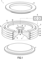
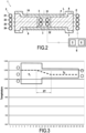
- THE figures 1 And 2 respectively present a perspective view and a sectional view of a device for generating a structure gradient microstructure according to the invention.
- annular mechanical part P for example a turbine disk, placed in a device 1 for generating a microstructure with a structure gradient.
- the mechanical part P Before any heat treatment by the device 1, the mechanical part P has a uniform fine-grained structure.
- the device 1 comprises a first heating inductor 2 and a second heating inductor 3.
- the mechanical part P and the first and second heating inductors 2 and 3 are shown in the figure 1 only partly.
- the first heating inductor 2 is formed of four turns 21, 22, 23 and 24 of radius greater than the external radius of the annular mechanical part P.
- the first heating inductor 2 is configured to heat the external periphery E of the mechanical part P to a first temperature T 1 higher than the solvus temperature, that is to say higher than the dissolution temperature of the phase blocking the grain boundaries.
- the second heating inductor 3 is formed of two turns 31 and 32 of radius less than the internal radius of the annular mechanical part P.
- the second heating inductor 3 is configured to heat the internal periphery I of said mechanical part P to a second temperature T 2 lower than the solvus temperature.
- the first heating inductor 2 forms a first closed enclosure inside which is arranged a second enclosure formed by the second heating inductor 3.
- the two enclosures formed by the two heating inductors 2 and 3 thus define an annular housing L extending between the two enclosures.
- the housing L is shaped to receive the annular mechanical part P.
- the device 1 can operate in air and does not require the installation of a vacuum structure in which the mechanical part P must be placed.
- the device 1 further comprises a control unit 4 to which the first heating inductor 2 and the second heating inductor 3 are electrically connected.
- the control unit 4 comprises input means, not shown, for inputting, as the case may be, two separate temperature setpoints for the two heating inductors 3 and 4 or the location of an intermediate zone.
- the location of the intermediate zone makes it possible to define the location of the transition zone between the fine grains and the coarse grains in the mechanical part P after treatment by the device 1.
- the control unit 4 is configured to deliver, from the information entered using the input means, a first temperature setpoint to the first heating inductor 2 and a second temperature setpoint to the second heating inductor 3.
- the first temperature setpoint and the second temperature setpoint are chosen so that the external part E of the mechanical part is at the first temperature T 1 , for example for a mechanical part P made of nickel-based alloy of the order of 1040 to 1060°C for a alloy of type Inco 718, or of the order of 1120 to 1140°C for an alloy of type AD730 or type Rene65, or of the order of 1160 to 1180°C for an alloy produced with a powder metallurgy of type N19, and that the internal part I of the mechanical part P is at the second temperature T 2 , for example for a mechanical part P in nickel-based alloy of the order of 980 to 1000°C for an alloy of type Inco 718, or of the order of 1060 to 1080°C for an alloy of type AD730 or type Rene65, or of the order of 1110 to 1130°C for an alloy produced with a powder metallurgy of type N
- the control unit 4 comprises a module 5 for regulating the heating temperature difference between the first heating inductor and the second heating inductor configured to determine the value of the first temperature setpoint and the second temperature setpoint as a function of the desired positioning of an intermediate zone between a coarse-grained structure and a fine-grained structure of the mechanical part.
- the control unit 4 further comprises a synchronization module 6 configured to coordinate the emission of the first and second temperature setpoints determined by the control unit 4 so that the first heating inductor 2 and the second heating inductor 3 operate simultaneously during a heating phase and/or a cooling phase of the generation of microstructure with a structure gradient.
- the coordination of the two heating inductors 2 and 3 using the synchronization means 6 of the control unit 4 makes it possible to simultaneously heat both the outside and the inside of the disk while controlling at all times the heating temperatures experienced by the different zones of the mechanical part P. Furthermore, by heating from both the inside and the outside of the part, the temperatures applied to the mechanical part P by the two inductors 2 and 3 can remain lower than the maximum temperatures permitted by the mechanical part P and thus avoid any risk of burning the part P since the internal zone of the mechanical part also receives heat energy from the second heating inductor 3.
- the heating inductors 2 and 3 maintain a regulated temperature difference between the zones of the mechanical part P.
- control unit 4 controls the temperature drop by adjusting the temperature setpoints applied to the first and second inductors 2 and 3 so as to constantly maintain the same temperature difference.
- the treatment process by device 1 can last between 15 min and 2 h.
- the device 1 comprises two insulators 7 and 8 each placed respectively on the lower face 9 and on the upper face 10 of the annular mechanical part P.
- the first insulator 7 is placed on the lower face 9 of the mechanical part P so as to cover the entire lower surface 9 of the mechanical part P extending from the external periphery E to the internal periphery I as well as the second inductor 3.
- the second insulator 8 is placed on the upper face 10 of the mechanical part P so as to cover the entire upper surface 10 of the mechanical part P extending from the internal periphery I to the external periphery E as well as the second inductor 3.
- insulators are particularly useful for very large mechanical parts P for which the distance between the first inductor 2 and the second inductor 3 is very large to the point that heat losses along the part can alter the heating efficiency by the two inductors 2 and 3.
- the invention thus provides a device for generating a microstructure with a structure gradient on an axisymmetric mechanical part hollowed out in its center, making it possible to adjust the temperatures in the areas of the mechanical part to be treated while reducing the thermomechanical stresses undergone by the part.
Landscapes
- Chemical & Material Sciences (AREA)
- Engineering & Computer Science (AREA)
- Physics & Mathematics (AREA)
- Mechanical Engineering (AREA)
- Crystallography & Structural Chemistry (AREA)
- Materials Engineering (AREA)
- Thermal Sciences (AREA)
- Metallurgy (AREA)
- Organic Chemistry (AREA)
- Electromagnetism (AREA)
- Powder Metallurgy (AREA)
- Turbine Rotor Nozzle Sealing (AREA)
- Heat Treatment Of Articles (AREA)
- Structures Of Non-Positive Displacement Pumps (AREA)
- General Induction Heating (AREA)
Applications Claiming Priority (2)
| Application Number | Priority Date | Filing Date | Title |
|---|---|---|---|
| FR1560653A FR3043410B1 (fr) | 2015-11-06 | 2015-11-06 | Dispositif de generation d'une microstructure a gradient de structure sur une piece axisymetrique |
| PCT/FR2016/052859 WO2017077248A1 (fr) | 2015-11-06 | 2016-11-04 | Dispositif de generation d'une microstructure a gradient de structure sur une piece axisymetrique |
Publications (2)
| Publication Number | Publication Date |
|---|---|
| EP3371334A1 EP3371334A1 (fr) | 2018-09-12 |
| EP3371334B1 true EP3371334B1 (fr) | 2025-01-29 |
Family
ID=55411499
Family Applications (1)
| Application Number | Title | Priority Date | Filing Date |
|---|---|---|---|
| EP16809130.4A Active EP3371334B1 (fr) | 2015-11-06 | 2016-11-04 | Dispositif et procédé de generation d'une microstructure a gradient de structure sur une piece axisymetrique |
Country Status (9)
| Country | Link |
|---|---|
| US (1) | US10837069B2 (enExample) |
| EP (1) | EP3371334B1 (enExample) |
| JP (1) | JP7166918B2 (enExample) |
| CN (1) | CN108431239B (enExample) |
| BR (1) | BR112018009147A8 (enExample) |
| CA (1) | CA3004391C (enExample) |
| FR (1) | FR3043410B1 (enExample) |
| RU (1) | RU2719236C2 (enExample) |
| WO (1) | WO2017077248A1 (enExample) |
Families Citing this family (6)
| Publication number | Priority date | Publication date | Assignee | Title |
|---|---|---|---|---|
| FR3104613B1 (fr) | 2019-12-11 | 2021-12-10 | Safran | Superalliage a base de nickel |
| CN112522494B (zh) * | 2020-12-01 | 2022-01-28 | 中国科学院金属研究所 | 一种双组织、双性能棒状材料梯度热处理的方法 |
| FR3133623A1 (fr) | 2022-03-17 | 2023-09-22 | Safran | Superalliage à base de nickel |
| US20240254589A1 (en) * | 2023-02-01 | 2024-08-01 | Raytheon Technologies Corporation | Selective heat treatment of metals using a coil-in-furnace system |
| US20240254611A1 (en) * | 2023-02-01 | 2024-08-01 | Raytheon Technologies Corporation | Single-step process for selective heat treatment of metals using multiple heating sources |
| US20240254578A1 (en) * | 2023-02-01 | 2024-08-01 | Raytheon Technologies Corporation | Selective heat treatment of metals using multiple induction heating coils |
Family Cites Families (20)
| Publication number | Priority date | Publication date | Assignee | Title |
|---|---|---|---|---|
| US2556236A (en) * | 1946-08-31 | 1951-06-12 | Ohio Crankshaft Co | Heat-treating method and product |
| US2556243A (en) * | 1949-02-23 | 1951-06-12 | Ohio Crankshaft Co | Means and method of simultaneous hardening of opposite surfaces of thin metallic members |
| US3741821A (en) | 1971-05-10 | 1973-06-26 | United Aircraft Corp | Processing for integral gas turbine disc/blade component |
| US4785147A (en) | 1986-06-25 | 1988-11-15 | Tocco, Inc. | System for hardening gears by induction heating |
| US5312497A (en) * | 1991-12-31 | 1994-05-17 | United Technologies Corporation | Method of making superalloy turbine disks having graded coarse and fine grains |
| US5527402A (en) * | 1992-03-13 | 1996-06-18 | General Electric Company | Differentially heat treated process for the manufacture thereof |
| RU2119842C1 (ru) | 1996-06-21 | 1998-10-10 | Институт проблем сверхпластичности металлов РАН | Способ изготовления осесимметричных деталей и способ получения заготовок для его осуществления (варианты) |
| RU2101883C1 (ru) * | 1996-12-06 | 1998-01-10 | Московский энергетический институт (Технический университет) | Индуктор для нагрева вращающихся деталей |
| US6145194A (en) * | 1999-05-28 | 2000-11-14 | Electric Power Research Institute, Inc. | Method for repairing a shrink-fitted turbine disc |
| JP4186328B2 (ja) | 1999-08-24 | 2008-11-26 | 株式会社Ihi | ディスクの部分加熱方法 |
| JP3820974B2 (ja) | 2000-12-04 | 2006-09-13 | Jfeスチール株式会社 | 鋼材の熱処理方法および熱処理装置 |
| US6660110B1 (en) * | 2002-04-08 | 2003-12-09 | The United States Of America As Represented By The Administrator Of The National Aeronautics And Space Administration | Heat treatment devices and method of operation thereof to produce dual microstructure superalloy disks |
| US6974508B1 (en) | 2002-10-29 | 2005-12-13 | The United States Of America As Represented By The United States National Aeronautics And Space Administration | Nickel base superalloy turbine disk |
| WO2005073515A1 (ja) | 2004-01-30 | 2005-08-11 | Ishikawajima-Harima Heavy Industries Co., Ltd. | ディスク材 |
| US8083872B2 (en) | 2007-08-03 | 2011-12-27 | Rolls-Royce Plc | Method of heat treating a superalloy component and an alloy component |
| US8721812B2 (en) * | 2009-04-07 | 2014-05-13 | Rolls-Royce Corporation | Techniques for controlling precipitate phase domain size in an alloy |
| US8496872B1 (en) * | 2010-07-20 | 2013-07-30 | The Boeing Company | High temperature nitriding of titanium parts |
| CN102643958B (zh) | 2012-04-26 | 2013-06-19 | 西北工业大学 | 盘形件梯度热处理装置 |
| CN103205545B (zh) * | 2013-02-04 | 2015-08-19 | 中国航空工业集团公司北京航空制造工程研究所 | 一种激光冲击处理发动机叶片的组合方法 |
| RU2548349C2 (ru) * | 2013-06-24 | 2015-04-20 | Федеральное государственное бюджетное учреждение науки Институт проблем сверхпластичности металлов Российской академии наук (ИПСМ РАН) | Способ изготовления осесимметричных деталей типа дисков |
-
2015
- 2015-11-06 FR FR1560653A patent/FR3043410B1/fr active Active
-
2016
- 2016-11-04 WO PCT/FR2016/052859 patent/WO2017077248A1/fr not_active Ceased
- 2016-11-04 CN CN201680074665.4A patent/CN108431239B/zh active Active
- 2016-11-04 BR BR112018009147A patent/BR112018009147A8/pt not_active Application Discontinuation
- 2016-11-04 EP EP16809130.4A patent/EP3371334B1/fr active Active
- 2016-11-04 CA CA3004391A patent/CA3004391C/fr active Active
- 2016-11-04 RU RU2018120600A patent/RU2719236C2/ru active
- 2016-11-04 US US15/773,917 patent/US10837069B2/en active Active
- 2016-11-04 JP JP2018522979A patent/JP7166918B2/ja active Active
Also Published As
| Publication number | Publication date |
|---|---|
| JP7166918B2 (ja) | 2022-11-08 |
| CN108431239A (zh) | 2018-08-21 |
| FR3043410B1 (fr) | 2017-12-08 |
| RU2719236C2 (ru) | 2020-04-17 |
| FR3043410A1 (fr) | 2017-05-12 |
| BR112018009147A2 (pt) | 2018-11-06 |
| RU2018120600A (ru) | 2019-12-06 |
| CN108431239B (zh) | 2021-03-12 |
| BR112018009147A8 (pt) | 2019-02-26 |
| US20180371563A1 (en) | 2018-12-27 |
| RU2018120600A3 (enExample) | 2020-02-27 |
| CA3004391C (fr) | 2023-09-26 |
| CA3004391A1 (fr) | 2017-05-11 |
| EP3371334A1 (fr) | 2018-09-12 |
| WO2017077248A1 (fr) | 2017-05-11 |
| US10837069B2 (en) | 2020-11-17 |
| JP2019500492A (ja) | 2019-01-10 |
Similar Documents
| Publication | Publication Date | Title |
|---|---|---|
| EP3371334B1 (fr) | Dispositif et procédé de generation d'une microstructure a gradient de structure sur une piece axisymetrique | |
| JP5850905B2 (ja) | 超合金部品及び合金部品の熱処理方法 | |
| JP5350603B2 (ja) | 超合金タービンブレードを熱処理するための固定治具の使用方法 | |
| US10669617B2 (en) | Methods for processing bonded dual alloy rotors including differential heat treatment processes | |
| EP2565294A1 (en) | Manufacturing a component of single crystal or directionally solidified material | |
| FR2906242A1 (fr) | Procede d'assemblage de pieces en ceramique refractaire par frittage a chaud avec champ electrique pulse ("sps") | |
| EP3014655B1 (fr) | Procédé de transfert d'une couche mince avec apport d'énergie thermique à une zone fragilisée via une couche inductive | |
| FR2970504A1 (fr) | Procede et dispositif d'alimentation en lubrifiant | |
| FR2680542A1 (fr) | Aile profilee comportant des moyens de refroidissement et procede de refroidissement de celle-ci. | |
| EP1649949A1 (fr) | Procédé de chauffage d'outillages d'engins de forge et élément de four amovible pour le chauffage de tels outillages | |
| CA2569755C (fr) | Installation d'affinage de silicium | |
| EP2556174B1 (fr) | Traitement d'une canne chauffante destinee a un pressuriseur du circuit primaire d'un reacteur nucleaire | |
| EP3022037B1 (fr) | Procédé d'assemblage de pièces de turbomachine | |
| EP3475012B1 (fr) | Four de refroidissement par solidification dirigée et procédé de refroidissement utilisant un tel four | |
| US8557063B2 (en) | Method for heat treating serviced turbine part | |
| FR2707272A1 (fr) | Perfectionnements apportés aux rouleaux refroidis pour la manutention de produits notamment métallurgiques et sidérurgiques. | |
| WO2024252087A1 (fr) | Procédé de traitement thermique d'une pièce métallique bi-matériaux et dispositif pour mettre en oeuvre ce procédé | |
| FR2972890A1 (fr) | Systeme inductif pouvant servir de creuset froid | |
| WO2025149643A1 (fr) | Dispositif de chauffage tel qu'une plaque de chauffage électrique utilisée dans l'industrie des semi-conducteurs | |
| FR3101560A1 (fr) | Procede de rechargement d’une piece metallique de turbomachine | |
| US20070158388A1 (en) | Apparatus and method for welding superalloys | |
| WO2021038163A1 (fr) | Four a induction comprenant un circuit resonant additionnel | |
| FR2933231A1 (fr) | Support pour une cible tournante | |
| FR3029211A1 (fr) | Procede de traitement thermochimique par apport de carbone et d’azote avec chauffage par induction | |
| WO2000037199A1 (fr) | Face laterale d'obturation de l'espace de coulee d'une installation de coulee continue de bandes minces metalliques |
Legal Events
| Date | Code | Title | Description |
|---|---|---|---|
| STAA | Information on the status of an ep patent application or granted ep patent |
Free format text: STATUS: UNKNOWN |
|
| STAA | Information on the status of an ep patent application or granted ep patent |
Free format text: STATUS: THE INTERNATIONAL PUBLICATION HAS BEEN MADE |
|
| PUAI | Public reference made under article 153(3) epc to a published international application that has entered the european phase |
Free format text: ORIGINAL CODE: 0009012 |
|
| STAA | Information on the status of an ep patent application or granted ep patent |
Free format text: STATUS: REQUEST FOR EXAMINATION WAS MADE |
|
| 17P | Request for examination filed |
Effective date: 20180503 |
|
| AK | Designated contracting states |
Kind code of ref document: A1 Designated state(s): AL AT BE BG CH CY CZ DE DK EE ES FI FR GB GR HR HU IE IS IT LI LT LU LV MC MK MT NL NO PL PT RO RS SE SI SK SM TR |
|
| AX | Request for extension of the european patent |
Extension state: BA ME |
|
| DAV | Request for validation of the european patent (deleted) | ||
| DAX | Request for extension of the european patent (deleted) | ||
| STAA | Information on the status of an ep patent application or granted ep patent |
Free format text: STATUS: EXAMINATION IS IN PROGRESS |
|
| 17Q | First examination report despatched |
Effective date: 20191202 |
|
| RAP3 | Party data changed (applicant data changed or rights of an application transferred) |
Owner name: SAFRAN |
|
| GRAP | Despatch of communication of intention to grant a patent |
Free format text: ORIGINAL CODE: EPIDOSNIGR1 |
|
| STAA | Information on the status of an ep patent application or granted ep patent |
Free format text: STATUS: GRANT OF PATENT IS INTENDED |
|
| INTG | Intention to grant announced |
Effective date: 20240919 |
|
| GRAS | Grant fee paid |
Free format text: ORIGINAL CODE: EPIDOSNIGR3 |
|
| GRAA | (expected) grant |
Free format text: ORIGINAL CODE: 0009210 |
|
| STAA | Information on the status of an ep patent application or granted ep patent |
Free format text: STATUS: THE PATENT HAS BEEN GRANTED |
|
| AK | Designated contracting states |
Kind code of ref document: B1 Designated state(s): AL AT BE BG CH CY CZ DE DK EE ES FI FR GB GR HR HU IE IS IT LI LT LU LV MC MK MT NL NO PL PT RO RS SE SI SK SM TR |
|
| REG | Reference to a national code |
Ref country code: GB Ref legal event code: FG4D Free format text: NOT ENGLISH |
|
| REG | Reference to a national code |
Ref country code: CH Ref legal event code: EP |
|
| REG | Reference to a national code |
Ref country code: DE Ref legal event code: R096 Ref document number: 602016091101 Country of ref document: DE |
|
| REG | Reference to a national code |
Ref country code: IE Ref legal event code: FG4D Free format text: LANGUAGE OF EP DOCUMENT: FRENCH |
|
| REG | Reference to a national code |
Ref country code: NL Ref legal event code: MP Effective date: 20250129 |
|
| PG25 | Lapsed in a contracting state [announced via postgrant information from national office to epo] |
Ref country code: NL Free format text: LAPSE BECAUSE OF FAILURE TO SUBMIT A TRANSLATION OF THE DESCRIPTION OR TO PAY THE FEE WITHIN THE PRESCRIBED TIME-LIMIT Effective date: 20250129 |
|
| PG25 | Lapsed in a contracting state [announced via postgrant information from national office to epo] |
Ref country code: RS Free format text: LAPSE BECAUSE OF FAILURE TO SUBMIT A TRANSLATION OF THE DESCRIPTION OR TO PAY THE FEE WITHIN THE PRESCRIBED TIME-LIMIT Effective date: 20250429 |
|
| PG25 | Lapsed in a contracting state [announced via postgrant information from national office to epo] |
Ref country code: FI Free format text: LAPSE BECAUSE OF FAILURE TO SUBMIT A TRANSLATION OF THE DESCRIPTION OR TO PAY THE FEE WITHIN THE PRESCRIBED TIME-LIMIT Effective date: 20250129 |
|
| PG25 | Lapsed in a contracting state [announced via postgrant information from national office to epo] |
Ref country code: PL Free format text: LAPSE BECAUSE OF FAILURE TO SUBMIT A TRANSLATION OF THE DESCRIPTION OR TO PAY THE FEE WITHIN THE PRESCRIBED TIME-LIMIT Effective date: 20250129 |
|
| PG25 | Lapsed in a contracting state [announced via postgrant information from national office to epo] |
Ref country code: ES Free format text: LAPSE BECAUSE OF FAILURE TO SUBMIT A TRANSLATION OF THE DESCRIPTION OR TO PAY THE FEE WITHIN THE PRESCRIBED TIME-LIMIT Effective date: 20250129 |
|
| REG | Reference to a national code |
Ref country code: LT Ref legal event code: MG9D |
|
| PG25 | Lapsed in a contracting state [announced via postgrant information from national office to epo] |
Ref country code: IS Free format text: LAPSE BECAUSE OF FAILURE TO SUBMIT A TRANSLATION OF THE DESCRIPTION OR TO PAY THE FEE WITHIN THE PRESCRIBED TIME-LIMIT Effective date: 20250529 Ref country code: NO Free format text: LAPSE BECAUSE OF FAILURE TO SUBMIT A TRANSLATION OF THE DESCRIPTION OR TO PAY THE FEE WITHIN THE PRESCRIBED TIME-LIMIT Effective date: 20250429 |
|
| REG | Reference to a national code |
Ref country code: AT Ref legal event code: MK05 Ref document number: 1763485 Country of ref document: AT Kind code of ref document: T Effective date: 20250129 |
|
| PG25 | Lapsed in a contracting state [announced via postgrant information from national office to epo] |
Ref country code: HR Free format text: LAPSE BECAUSE OF FAILURE TO SUBMIT A TRANSLATION OF THE DESCRIPTION OR TO PAY THE FEE WITHIN THE PRESCRIBED TIME-LIMIT Effective date: 20250129 |
|
| PG25 | Lapsed in a contracting state [announced via postgrant information from national office to epo] |
Ref country code: PT Free format text: LAPSE BECAUSE OF FAILURE TO SUBMIT A TRANSLATION OF THE DESCRIPTION OR TO PAY THE FEE WITHIN THE PRESCRIBED TIME-LIMIT Effective date: 20250529 Ref country code: LV Free format text: LAPSE BECAUSE OF FAILURE TO SUBMIT A TRANSLATION OF THE DESCRIPTION OR TO PAY THE FEE WITHIN THE PRESCRIBED TIME-LIMIT Effective date: 20250129 |
|
| PG25 | Lapsed in a contracting state [announced via postgrant information from national office to epo] |
Ref country code: BG Free format text: LAPSE BECAUSE OF FAILURE TO SUBMIT A TRANSLATION OF THE DESCRIPTION OR TO PAY THE FEE WITHIN THE PRESCRIBED TIME-LIMIT Effective date: 20250129 Ref country code: GR Free format text: LAPSE BECAUSE OF FAILURE TO SUBMIT A TRANSLATION OF THE DESCRIPTION OR TO PAY THE FEE WITHIN THE PRESCRIBED TIME-LIMIT Effective date: 20250430 |
|
| PG25 | Lapsed in a contracting state [announced via postgrant information from national office to epo] |
Ref country code: AT Free format text: LAPSE BECAUSE OF FAILURE TO SUBMIT A TRANSLATION OF THE DESCRIPTION OR TO PAY THE FEE WITHIN THE PRESCRIBED TIME-LIMIT Effective date: 20250129 |
|
| PG25 | Lapsed in a contracting state [announced via postgrant information from national office to epo] |
Ref country code: SE Free format text: LAPSE BECAUSE OF FAILURE TO SUBMIT A TRANSLATION OF THE DESCRIPTION OR TO PAY THE FEE WITHIN THE PRESCRIBED TIME-LIMIT Effective date: 20250129 |
|
| PG25 | Lapsed in a contracting state [announced via postgrant information from national office to epo] |
Ref country code: SM Free format text: LAPSE BECAUSE OF FAILURE TO SUBMIT A TRANSLATION OF THE DESCRIPTION OR TO PAY THE FEE WITHIN THE PRESCRIBED TIME-LIMIT Effective date: 20250129 |
|
| PG25 | Lapsed in a contracting state [announced via postgrant information from national office to epo] |
Ref country code: DK Free format text: LAPSE BECAUSE OF FAILURE TO SUBMIT A TRANSLATION OF THE DESCRIPTION OR TO PAY THE FEE WITHIN THE PRESCRIBED TIME-LIMIT Effective date: 20250129 |
|
| PG25 | Lapsed in a contracting state [announced via postgrant information from national office to epo] |
Ref country code: IT Free format text: LAPSE BECAUSE OF FAILURE TO SUBMIT A TRANSLATION OF THE DESCRIPTION OR TO PAY THE FEE WITHIN THE PRESCRIBED TIME-LIMIT Effective date: 20250129 |
|
| PG25 | Lapsed in a contracting state [announced via postgrant information from national office to epo] |
Ref country code: CZ Free format text: LAPSE BECAUSE OF FAILURE TO SUBMIT A TRANSLATION OF THE DESCRIPTION OR TO PAY THE FEE WITHIN THE PRESCRIBED TIME-LIMIT Effective date: 20250129 Ref country code: EE Free format text: LAPSE BECAUSE OF FAILURE TO SUBMIT A TRANSLATION OF THE DESCRIPTION OR TO PAY THE FEE WITHIN THE PRESCRIBED TIME-LIMIT Effective date: 20250129 |
|
| PG25 | Lapsed in a contracting state [announced via postgrant information from national office to epo] |
Ref country code: RO Free format text: LAPSE BECAUSE OF FAILURE TO SUBMIT A TRANSLATION OF THE DESCRIPTION OR TO PAY THE FEE WITHIN THE PRESCRIBED TIME-LIMIT Effective date: 20250129 |
|
| PG25 | Lapsed in a contracting state [announced via postgrant information from national office to epo] |
Ref country code: SK Free format text: LAPSE BECAUSE OF FAILURE TO SUBMIT A TRANSLATION OF THE DESCRIPTION OR TO PAY THE FEE WITHIN THE PRESCRIBED TIME-LIMIT Effective date: 20250129 |
|
| REG | Reference to a national code |
Ref country code: DE Ref legal event code: R097 Ref document number: 602016091101 Country of ref document: DE |
|
| PLBE | No opposition filed within time limit |
Free format text: ORIGINAL CODE: 0009261 |
|
| STAA | Information on the status of an ep patent application or granted ep patent |
Free format text: STATUS: NO OPPOSITION FILED WITHIN TIME LIMIT |