EP3371118B1 - Mold shuttle positioning system for a glass sheet forming system - Google Patents
Mold shuttle positioning system for a glass sheet forming system Download PDFInfo
- Publication number
- EP3371118B1 EP3371118B1 EP16862845.1A EP16862845A EP3371118B1 EP 3371118 B1 EP3371118 B1 EP 3371118B1 EP 16862845 A EP16862845 A EP 16862845A EP 3371118 B1 EP3371118 B1 EP 3371118B1
- Authority
- EP
- European Patent Office
- Prior art keywords
- mold
- shuttle
- glass sheet
- frame
- support
- Prior art date
- Legal status (The legal status is an assumption and is not a legal conclusion. Google has not performed a legal analysis and makes no representation as to the accuracy of the status listed.)
- Active
Links
Images


Classifications
-
- C—CHEMISTRY; METALLURGY
- C03—GLASS; MINERAL OR SLAG WOOL
- C03B—MANUFACTURE, SHAPING, OR SUPPLEMENTARY PROCESSES
- C03B17/00—Forming molten glass by flowing-out, pushing-out, extruding or drawing downwardly or laterally from forming slits or by overflowing over lips
- C03B17/06—Forming glass sheets
-
- C—CHEMISTRY; METALLURGY
- C03—GLASS; MINERAL OR SLAG WOOL
- C03B—MANUFACTURE, SHAPING, OR SUPPLEMENTARY PROCESSES
- C03B35/00—Transporting of glass products during their manufacture, e.g. hot glass lenses, prisms
- C03B35/14—Transporting hot glass sheets or ribbons, e.g. by heat-resistant conveyor belts or bands
- C03B35/20—Transporting hot glass sheets or ribbons, e.g. by heat-resistant conveyor belts or bands by gripping tongs or supporting frames
- C03B35/202—Transporting hot glass sheets or ribbons, e.g. by heat-resistant conveyor belts or bands by gripping tongs or supporting frames by supporting frames
- C03B35/207—Construction or design of supporting frames
-
- C—CHEMISTRY; METALLURGY
- C03—GLASS; MINERAL OR SLAG WOOL
- C03B—MANUFACTURE, SHAPING, OR SUPPLEMENTARY PROCESSES
- C03B23/00—Re-forming shaped glass
- C03B23/02—Re-forming glass sheets
- C03B23/023—Re-forming glass sheets by bending
-
- C—CHEMISTRY; METALLURGY
- C03—GLASS; MINERAL OR SLAG WOOL
- C03B—MANUFACTURE, SHAPING, OR SUPPLEMENTARY PROCESSES
- C03B23/00—Re-forming shaped glass
- C03B23/02—Re-forming glass sheets
- C03B23/023—Re-forming glass sheets by bending
- C03B23/03—Re-forming glass sheets by bending by press-bending between shaping moulds
-
- C—CHEMISTRY; METALLURGY
- C03—GLASS; MINERAL OR SLAG WOOL
- C03B—MANUFACTURE, SHAPING, OR SUPPLEMENTARY PROCESSES
- C03B23/00—Re-forming shaped glass
- C03B23/02—Re-forming glass sheets
- C03B23/023—Re-forming glass sheets by bending
- C03B23/035—Re-forming glass sheets by bending using a gas cushion or by changing gas pressure, e.g. by applying vacuum or blowing for supporting the glass while bending
- C03B23/0352—Re-forming glass sheets by bending using a gas cushion or by changing gas pressure, e.g. by applying vacuum or blowing for supporting the glass while bending by suction or blowing out for providing the deformation force to bend the glass sheet
- C03B23/0357—Re-forming glass sheets by bending using a gas cushion or by changing gas pressure, e.g. by applying vacuum or blowing for supporting the glass while bending by suction or blowing out for providing the deformation force to bend the glass sheet by suction without blowing, e.g. with vacuum or by venturi effect
-
- C—CHEMISTRY; METALLURGY
- C03—GLASS; MINERAL OR SLAG WOOL
- C03B—MANUFACTURE, SHAPING, OR SUPPLEMENTARY PROCESSES
- C03B35/00—Transporting of glass products during their manufacture, e.g. hot glass lenses, prisms
- C03B35/14—Transporting hot glass sheets or ribbons, e.g. by heat-resistant conveyor belts or bands
- C03B35/145—Transporting hot glass sheets or ribbons, e.g. by heat-resistant conveyor belts or bands by top-side transfer or supporting devices, e.g. lifting or conveying using suction
-
- C—CHEMISTRY; METALLURGY
- C03—GLASS; MINERAL OR SLAG WOOL
- C03B—MANUFACTURE, SHAPING, OR SUPPLEMENTARY PROCESSES
- C03B35/00—Transporting of glass products during their manufacture, e.g. hot glass lenses, prisms
- C03B35/14—Transporting hot glass sheets or ribbons, e.g. by heat-resistant conveyor belts or bands
- C03B35/20—Transporting hot glass sheets or ribbons, e.g. by heat-resistant conveyor belts or bands by gripping tongs or supporting frames
-
- C—CHEMISTRY; METALLURGY
- C03—GLASS; MINERAL OR SLAG WOOL
- C03B—MANUFACTURE, SHAPING, OR SUPPLEMENTARY PROCESSES
- C03B2225/00—Transporting hot glass sheets during their manufacture
- C03B2225/02—Means for positioning, aligning or orientating the sheets during their travel, e.g. stops
-
- Y—GENERAL TAGGING OF NEW TECHNOLOGICAL DEVELOPMENTS; GENERAL TAGGING OF CROSS-SECTIONAL TECHNOLOGIES SPANNING OVER SEVERAL SECTIONS OF THE IPC; TECHNICAL SUBJECTS COVERED BY FORMER USPC CROSS-REFERENCE ART COLLECTIONS [XRACs] AND DIGESTS
- Y02—TECHNOLOGIES OR APPLICATIONS FOR MITIGATION OR ADAPTATION AGAINST CLIMATE CHANGE
- Y02P—CLIMATE CHANGE MITIGATION TECHNOLOGIES IN THE PRODUCTION OR PROCESSING OF GOODS
- Y02P40/00—Technologies relating to the processing of minerals
- Y02P40/50—Glass production, e.g. reusing waste heat during processing or shaping
- Y02P40/57—Improving the yield, e-g- reduction of reject rates
Definitions
- This invention relates to a mold shuttle positioning system for forming and transporting a hot glass sheet in a glass sheet bending system.
- a mold shuttle positioning system for forming a hot glass sheet in a glass processing system includes a mold having a surface that defines an initial shape to which the glass sheet is to be formed.
- the mold may include a vacuum chamber connected to a vacuum source, and a set of openings that extend from the mold surface into the vacuum chamber.
- the shuttle system also includes a mold support frame including at least one connection surface for mounting the mold thereon.
- the shuttle system also includes a shuttle frame including a pair of generally parallel elongate beams, each of the beams including at least one support surface near one end of the beam for receiving and supporting the mold support frame thereon.
- At least one mold guide may be mounted on the support surface of one of the beams for receiving and fixing the position of the mold support frame relative to the shuttle frame to prevent movement of the mold support frame with respect to the shuttle frame in any direction as the mold support frame is supported thereon.
- At least one other mold guide may be provided, which guide is mounted on the support surface of the other one of the beams for receiving and fixing the position of the mold support frame relative to the shuttle frame to prevent movement of the mold support frame in a first direction with respect to the shuttle frame, but allow movement of the mold support frame in a second direction with respect to the shuttle frame as the mold support frame is supported thereon.
- At least one support wheel assembly is mounted in proximity to each of the shuttle beams to position and support each one of the beams as the shuttle frame is moved to position the mold supported thereon at one of multiple desired processing locations.
- Each support wheel assembly includes a support wheel, and may also include an actuator for selectively moving the support wheel and the beam supported thereon in a generally vertical direction.
- the shuttle frame also includes a drive assembly which moves the supported shuttle beams on the support wheel(s) in a generally lateral direction,
- At least one shuttle guide may be mounted on at least one of the support wheel assemblies associated with only one of the beams to locate and prevent movement of the associated shuttle beam in a first lateral direction with respect to the heating and forming system, but allow movement of the shuttle in a second lateral direction with respect to the heating and forming system as the shuttle and mold are positioned for processing the glass sheet in multiple locations within the heating and forming system.
- At least one alignment wheel assembly may be mounted to position each one of the beams as the shuttle frame is moved to position the mold at one of multiple desired locations, the alignment wheel assembly including an alignment wheel for vertically aligning the beam as the shuttle is positioned.
- At least one alignment guide may be mounted on at least one of the alignment wheel assemblies associated with only one of the beams for receiving and laterally aligning the associated shuttle beam relative to a selected point on the heating and forming system to locate and prevent movement of the shuttle in a first lateral direction with respect to the heating and forming system, but allow movement of the shuttle in a second lateral direction with respect to the heating and forming system as the shuttle and mold are positioned for processing the glass sheet in multiple locations within the heating and forming system.
- the mold includes a full downwardly facing surface and a vacuum chamber having a set of openings that extend from the surface into the vacuum chamber
- the mold support frame includes at least one mold conduit operably connected at a first location to the vacuum chamber and including an opening at a second location defining a first coupling port.
- At least one vacuum source may be mounted on the shuttle frame near the end of the beam opposite the end including the mold support frame support surface.
- At least one shuttle conduit may be operably connected at a first location to the vacuum source and include an opening at a second location defining a second coupling port.
- a connector may be provided for releasably connecting a first coupling port to a second coupling port to provide communication of the vacuum from the vacuum source through the shuttle conduit and through the mold conduit to the vacuum chamber for selectively drawing a vacuum at the downwardly facing surface of the mold.
- a mold shuttle positioning system including one or more of the above-described aspects of the disclosure is provided for use in a three stage forming station for forming a hot glass sheet, wherein the mold shuttle positioning system includes a first upper vacuum mold having a full downwardly facing surface that defines an initial shape.
- the three stage forming station includes an upwardly facing lower mold which receives the glass sheet from the first upper mold so the glass sheet sags under gravity.
- a downwardly facing second upper mold of the forming station is complementary to the upwardly facing lower mold and cooperates with the lower mold to form the glass sheet with curvature corresponding to the shapes of the lower mold and the second upper mold.
- the three stage forming station also includes a conveyor from which the first upper mold receives the glass sheet prior to the shuttle including the first upper mold being moved laterally to move the glass sheet above the lower mold, which lower mold then receives the glass sheet for subsequently performing further forming with the second upper mold.
- This disclosed embodiment also includes a housing having a heated chamber, and has the conveyor embodied by a roll conveyor for conveying the hot glass sheet into the heated chamber of the housing along a horizontal plane of conveyance. The shuttle is movable laterally within the heated chamber to position the first upper mold between a pickup position above the roll conveyor and a delivery position spaced laterally from the pickup position.
- a gas lift jet array may be located below the plane of conveyance to supply upwardly directed gas jets for lifting the glass sheet upwardly from the roll conveyor to the first upper mold when located in its pickup position to initially form and support the glass sheet against the downwardly facing surface of the first upper mold.
- the second upper mold is spaced laterally within the heated chamber from the pickup position of the first upper mold and is movable vertically between an upper position located above the elevation of the plane of conveyance and a lower position closer to the elevation of the plane of conveyance, and the second upper mold has a downwardly facing surface of a downwardly convex shape that further defines the desired curvature of the glass sheet.
- a second vacuum source may be provided to selectively draw a vacuum at the downwardly facing surface of the second upper mold.
- the lower mold is located within the heated chamber below the second upper mold and is also below the first upper mold after movement of the shuttle and first upper mold to its delivery position with the glass sheet supported thereon by vacuum drawn by the shuttle vacuum source.
- the shuttle vacuum may then be terminated to release the glass sheet onto the lower mold, and the shuttle operated to move the first upper mold back to its pickup position.
- the second upper mold is then moved downwardly from its upper position to its lower position to cooperate with the lower mold to further press form the glass sheet, and the second upper mold is subsequently moved upwardly to its upper position with the formed glass sheet supported on the second upper mold by vacuum drawn at its downwardly facing surface by a vacuum source associated with the second upper mold.
- a delivery mold is moved to below the formed glass sheet on the second upper mold in its upper position whereupon the vacuum is terminated and the glass sheet is released from the second upper mold onto the delivery mold which is then moved out of the forming station for delivery of the formed glass sheet.
- One or more controllers may be utilized to operate the heating chamber, the roll conveyor, the shuttle system including the first upper mold, the gas lift jet array, the second upper mold, the vacuum source, the lower mold, and the delivery mold to perform the forming of the glass sheet and its delivery.
- a first support wheel assembly including a shuttle guide and a first alignment wheel assembly including an alignment guide are each mounted to receive one of the shuttle beams at a fixed position with respect to the conveyor (e.g., at a relatively upstream location), while a second support wheel assembly and a second alignment wheel assembly (each without a shuttle guide or an alignment guide) are each mounted to receive the other shuttle beam at another fixed position with respect to the conveyor (e.g., at a relatively downstream location).
- This arrangement thereby ensures that the shuttle is registered at a fixed selected (e.g., the upstream) location as it is positioned and repositioned between a pickup position above the roll conveyor and a delivery position in the forming station spaced laterally from the pickup position, while the second support wheel assembly and second alignment wheel assembly support and vertically align the other shuttle beam as it is positioned but do not fix this beam in an upstream/downstream location, thereby allowing for some movement of this shuttle beam as a result of thermal expansion/contraction of the shuttle.
- a fixed selected e.g., the upstream
- the mold guide for receiving and fixing the position of the mold support frame relative to the shuttle frame to prevent movement of the mold support frame with respect to the shuttle frame in any direction is mounted on the same shuttle beam as the first support wheel assembly and the first alignment wheel assembly, to thereby ensure that the mold is similarly registered at a fixed selected location with respect to the mold shuttle (and, thereby, the conveyor (e.g., upstream), while a second mold guide is mounted on the support surface of the other (e.g., downstream) shuttle beam for receiving and fixing the position of the mold support frame relative to the shuttle frame to prevent movement of the mold support frame in a first direction with respect to the shuttle frame (e.g., along the length of the shuttle beam), but allow movement of the mold support frame in a second direction (e.g., upstream/downstream), thereby similarly allowing for some movement of the mold and mold frame relative to this shuttle beam as a result of thermal expansion/contraction.
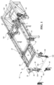
- a mold shuttle positioning system for use in forming a hot glass sheet in a glass processing system includes a mold 12 having a surface that defines the initial shape to which the glass sheet is to be formed.
- the mold may include a vacuum chamber connected to at least one vacuum source (two of which are shown in Figure 1 as v 1 and v 2 ), and a set of openings (shown as 82 in Figure 13 ) that extend from the mold surface into the vacuum chamber.
- the shuttle system also includes a mold support frame 16 including at least one connection surface 18 for mounting the mold 12 thereon.
- the shuttle system 10 also includes a shuttle frame 20 including a pair of generally parallel elongate beams 22, 24, each of the beams 22, 24 including at least one support surface 26, 28 near one end of the beam for receiving and supporting the mold support frame 16 thereon.
- the shuttle system 10 also includes at least one support wheel assembly (two are shown as 30 and 32) mounted in proximity to each one of the shuttle beams 22, 24 to position and support each one of the beams 22, 24 as the shuttle frame 20 is moved horizontally and vertically to position the mold 12 at one of multiple desired processing locations.
- at least one support wheel assembly (two are shown as 30 and 32) mounted in proximity to each one of the shuttle beams 22, 24 to position and support each one of the beams 22, 24 as the shuttle frame 20 is moved horizontally and vertically to position the mold 12 at one of multiple desired processing locations.
- Each support wheel assembly 30, 32 includes a support wheel 34, 36 to support beams 22, 24 as the mold shuttle 20 (and each of the beams 22, 24) are moved in a generally horizontal direction.
- the support wheel assemblies 30, 32 may also include an actuator 38 for selectively moving each of the support wheels 34, 36 and the shuttle beams 22, 24 supported thereon in a generally vertical direction when desired (as described in greater detail hereinafter).
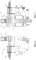
- At least one shuttle guide 40 may be mounted on at least one of the support wheel assemblies 32 associated with only one of the beams 24 for receiving and fixing the position of the shuttle frame 20 relative to the forming station (shown as 210 in Figure 13 ) of the heating and forming system (shown as 200 in Figure 13 ) to locate and prevent movement of the shuttle frame 20 in a first lateral direction with respect to the heating and forming system 200, but allow movement of the shuttle frame 20 in a second lateral direction with respect to the heating and forming system 200 as the shuttle frame 20 and mold (shown as 12 in Figure 1 , and 12' in Figure 13 ) are positioned for processing the glass sheet in multiple locations within the heating and forming system 200.
- shuttle guide 40 includes a pair of rotating guide wheels 42 and 44 mounted on opposite sides of beam 24 to contact the opposing sides of beam 24 and position the beam as it is conveyed atop support wheel 36.
- each of support wheel assemblies 30 and 32 may be provided with cooling channels 60, 62 through which coolant may be circulated to cool any selected support wheel assembly components.
- Shuttle guide 40 may similarly include cooling channels and coolant for cooling selected components of the shuttle guide.
- At least one alignment wheel assembly 46, 48 may be mounted to support and vertically position, respectively, each one of beams 22 and 24 as the shuttle frame 20 is moved to position the mold 12 at one of multiple desired locations.
- the alignment wheel assembly 46, 48 includes an alignment wheel 50, 52 for supporting and positioning, respectively, each of beams 22 and 24.
- Each alignment wheel assembly 46, 48 may also include an actuator 114, 112, or, alternatively, a spring mechanism, which is operably connected to the alignment wheel 50, 52 to provide some cushioning and vertical positioning as the shuttle beam 22, 24 is moved onto the wheel 50, 52.
- At least one alignment guide 54 may be mounted on at least one of the alignment wheel assemblies 48 associated with only one of the beams 24 for receiving and aligning the shuttle frame 20 relative to the heating and forming system 200 to locate and prevent movement of the shuttle frame 20 in a first lateral direction with respect to the heating and forming system 200, but allow movement of the shuttle frame 20 in a second lateral direction (i.e., the direction of travel of the shuttle frame 20) with respect to the heating and forming system 200 as the shuttle frame 20 and mold 12 are positioned for processing the glass sheet in multiple locations within the heating and forming system 200.
- alignment guide 54 includes a pair of rotating guide wheels 56 and 58 mounted on opposite sides of beam 24 to contact the opposing sides of beam 24 as the beam is conveyed atop alignment wheel 52.
- a cushioning mechanism such as a spring 116, 118, or, alternatively an air cylinder, may be operably connected to each guide wheel 56, 58 to provide some compliance as the beam 24 contacts the guide wheel 56, 58.
- the shuttle frame 20 may be driven by conventional drive mechanism, such as, for example belt-drive mechanism 64, as shown in Figure 1 , to position the shuttle frame 20 at the various desired positions required for the glass forming system with which the shuttle frame 20 is employed.
- the drive 64 shown in Figure 1
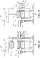
- the drive 64 may be controlled to position the shuttle frame 20 to and from (1) a fully retracted position where the mold 12, 12' is positioned outside of the heated ambient of the glass sheet forming system, such as, for example, when the mold is being changed, or when the mold and/or shuttle are being maintained or repaired, (2) its initial glass pickup position, shown in Figure 13 , and ( 3 ) its final forming station position, shown in Figure 14 .
- other conventional drive mechanisms may be employed to move shuttle frame 20, 20 .
- the mold 12 may include a full downwardly facing surface 80 that defines the initial shape to which the glass sheet is to be formed and a vacuum chamber having a set of openings 82 (shown in Figure 13 ) that extend from the surface into the vacuum chamber.
- the mold support frame 16 includes at least one mold conduit 84 operably connected at a first location to the vacuum chamber and including an opening at a second location defining a first coupling port 86.
- At least one vacuum source such as a vacuum generator, shown in Figure 1 as v 1 and/or v 2 , may be mounted on the shuttle frame 20 near the end of one or both of the beams 22, 24 opposite the end including the mold support frame support surfaces 26 and 28.
- At least one shuttle conduit 88 may be operably connected at a first location to a vacuum generator and include an opening at a second location defining a second coupling port 90.
- a connector 92 may be provided for releasably connecting a first coupling port to a second coupling port to provide communication of the vacuum from the vacuum source through the shuttle conduit and through the mold conduit to the vacuum chamber for selectively drawing a vacuum at the downwardly facing surface of the mold. Additional details of the vacuum mold shuttle assembly including the quick connecting coupling ports may be found in United States Application Serial No. 62/249,567 (Attorney Docket No. GLT 1990 PRV.
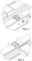
- a first mold guide 66 is mounted on one of the contacting surfaces 28 of one of the beams (shown on beam 24) to receive and fix the position of the mold support frame 16 (and mold 12) relative to the shuttle frame 20 to prevent movement of the mold support frame 16 with respect to the shuttle frame 20 in any direction as the mold support frame is supported thereon.
- the first guide 66 may include an alignment key 68 which is fixed to extend upwardly from the beam support surface 28 (or, alternatively, project downwardly from the mold frame 16), and a complimentary receiver (or keyway) 70 located on the mold support frame 16 (or, alternatively, on the beam support surface 28) such that, when the mold 12 and mold support frame 16 are installed on the shuttle frame 20, alignment key 68 is received within keyway 70, thereby aligning the mold 12 in a fixed position.
- the mold guide alignment key 68 is shaped as a "+", such that engagement of the correspondingly shaped keyway 70 on the mold frame 16 assures that the mold frame 16 is fixed in position relative to beam 24 at the location of the guide 66.
- key 68 and keyway 70 may alternatively be configured in other complimentary shapes, such as an "X”, so long as engagement of key 68 within keyway 70 restricts all movement of the mold frame 16 with respect to beam 24 of the shuttle frame 20 at this location.
- a second mold guide 72 (best shown in Figure 5 ) may be provided, which mold guide 72 may be mounted on the support surface 26 of the other one of the beams 22 to register the mold frame 16 in the desired location on beam 22.
- the guide 72 associated with beam 22 includes a second key 74 and complimentary shaped keyway which are mounted, respectively, on beam 22 and mold frame 16 (or vice versa ) to fix the positioning of mold frame 16 along one axis (such as the length) of the beam 22, but allow for movement of mold frame 16 along another axis (such as the width) of the beam 22 to prevent movement of the mold support frame 16 in a first direction with respect to the shuttle frame 20 (e.g., parallel to the horizontal direction of travel of the shuttle frame 20), but allow movement of the mold support frame 16 in a second direction with respect to the shuttle frame 20 (e.g., transverse to the direction of travel of the shuttle frame 20) as the mold support frame 16 is supported thereon.
- a second key 74 and complimentary shaped keyway which are mounted, respectively, on beam 22 and mold frame 16 (or vice versa ) to fix the positioning of mold frame 16 along one axis (such as the length) of the beam 22, but allow for movement of mold frame 16 along another axis (such as the width) of
- the second key 74 on mold guide 72 is shaped as a "-", and the corresponding keyway is a slot which is suitably sized to accept the key 74 therein, but allow the key to slide in one direction (such as, for example, transverse to the length of the shuttle frame.
- mold 12 and mold frame 16 are aligned at a fixed position along the length of the shuttle support beams 22, 24 as well as at a fixed position with respect to one of the beams 24, but the mold 12 and mold frame 16 are allowed to move in a direction transverse to beam 22, to align the mold at a fixed point on the shuttle frame 20, but allow for, for example, any thermal expansion or contraction that may result as the mold 12 and mold frame 16 are moved into and out of the heated ambient.
- each of support wheel assembly 32 and alignment wheel assembly 48 includes, respectively, shuttle guide 40 and alignment guide 54 for receiving and maintaining beam 24 of the shuttle frame 20 in a fixed location in a direction transverse to the direction of conveyance of the shuttle (for example, at the upstream side of conveyor 206 shown in Figure 12 ), while each of support wheel assembly 30 and alignment wheel assembly 46 do not include guides, thereby allowing for some movement of beam 22 in a direction transverse to the direction of conveyance of the shuttle frame 20 (for example, at the downstream side of conveyor 206) to accommodate thermal expansion/contraction of the shuttle frame 20.
- mold guide 66 similarly restricts movement of mold 12, also with respect to beam 24, while mold guide 72 allows for some movement of the mold support 16 on beam 22 in a direction transverse to the direction of travel of the shuttle frame 20, also to accommodate thermal expansion/contraction of the mold 12 and/or mold support 16 in that direction.
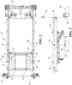
- the disclosed mold shuttle positioning system 10 may be employed in a glass sheet forming system generally indicated by 200 which includes a furnace 202 having a heating chamber 204 for providing a heated ambient for heating glass sheets.
- a conveyor 206 of the system conveys the heated glass sheet in a generally horizontally extending orientation and is preferably of the roll conveyor type including rolls 208 like those disclosed by United States Patent Nos.: 3,806,312 McMaster ; 3,934,970 McMaster et al. , 3,947,242 McMaster et al .; and 3,994,711 McMaster et al.
- a three stage forming station 210 of the system 200 is constructed according to the present disclosure and performs the method thereof such that both the forming station and the forming method are described in an integrated manner to facilitate an understanding of different aspects of the disclosure.
- the forming station 210 has a construction with press forming somewhat similar to that of the disclosure of the aforementioned United States Patent 4,661,141 and the other United States Patents set forth in the above Background section of this application.
- the forming station 210 has an insulated housing 212 defining a heated chamber 214 in which forming apparatus 216 of the forming station is located as best shown in Figure 13 .
- the glass sheet forming apparatus 216 may employ the disclosed mold shuttle positioning system 10', including a first upper mold 12' that picks up the softened glass sheet from the heater conveyor 206 during a first stage of the hot glass sheet forming, then moves the glass sheet horizontally to a delivery position shown in Figure 14 where a lower mold 222 is located, and releases the glass sheet G onto the lower mold 222 for partially forming the glass by gravity sagging. It should be noted that, in this disclosed embodiment, there is a relatively limited time for gravity sagging so that the shape can be more accurately controlled.
- the first upper mold 12' moves back from its delivery position of Figure 14 to its pickup position of Figure 13 and the second upper mold 220 moves downwardly as shown in Figure 15 to cooperate with the lower mold 222 in press forming the glass sheet.
- Some vacuum forming of the glass on the facing surface 270 of the second upper mold 220 may also be accomplished if desired.
- the second upper mold 220 moves upwardly with the glass sheet supported against its downwardly facing surface 270 by a drawn vacuum and the delivery mold 224 shown in Figure 13 is moved from a post-forming station (such as, for example, the quench station 226) into the forming station 210 to receive the formed glass sheet for movement out of the forming station 210 (such as to the quench station 226 of the disclosed embodiment) for further processing.
- a post-forming station such as, for example, the quench station 226
- the delivery mold 224 shown in Figure 13 is moved from a post-forming station (such as, for example, the quench station 226) into the forming station 210 to receive the formed glass sheet for movement out of the forming station 210 (such as to the quench station 226 of the disclosed embodiment) for further processing.
- the first upper mold 12' has a support frame 16' that is supported by a shuttle frame 20' including elongated beams 22', 24' (only one shown) that are moved by an actuator 242 through a connection 244 (such as, for example, a suitably controlled drive mechanism 64 as shown in Figure 1 ).
- a connection 244 such as, for example, a suitably controlled drive mechanism 64 as shown in Figure 1 .
- These beams 22', 24' are supported by associated support rollers 246 that are mounted on an actuator 248 to provide vertical movement of the beams (and hence vertical movement of the first upper mold 12') during its operation.
- the first upper mold 12' can be moved downwardly, for example, to about one half inch (12 to 15 mm) from the conveyor 206 for the initial pickup of the glass sheet and can then be moved upwardly so as to move above covers 250 located above the ends of the conveyor rolls 208.
- Lateral rollers 252 also contact the beams to provide lateral positioning during movement of the first upper mold 12' between its pickup position shown in Figure 13 and its delivery position shown in Figure 14 .
- Additional alignment rollers 260, 262 may be located on the exit side of the forming station 210, as best shown in Figure 14 , to support and position beams 22', 24' when the shuttle frame 20' and mold 12' are moved to the delivery position.
- the glass sheet may be formed on the first upper mold 12' with curvature in a first direction and straight line elements in a second direction transverse to the first direction, by gravity on the lower mold 222 after receipt thereby from the first upper mold 12' in its delivery position shown in Figure 14 , and finally by the press forming between the second upper mold 220 and the lower mold 222 and/or vacuum forming on the second upper mold 220 as shown in Figure 15 .
- the disclosed mold shuttle positioning system 10 may be employed in other multi-stage forming systems, such as other embodiments of three stage forming systems, which forming systems may include additional details as are disclosed in United States Patent No. 9,452,458 B2 , entitled "Three Stage Forming Station And Method For Forming A Hot Glass Sheet With Transverse Curvature".
- the lower mold 222 as illustrated may be supported by a framework 254 that is supported by actuators 256, such as screw jacks, for vertical movement.
- This vertical movement can be downward to allow the first upper mold 12' to move over the lower mold 222 and then upward so that the release of the glass sheet is at a more closely spaced relationship to control positioning.
- the vertical movement of the lower mold 222 can also be used in cooperation with the vertical movement of the second upper mold 220 to perform the press bending.
- a gas lift jet array 258 may be included in the forming station as illustrated in Figure 13 .
- the gas lift jet array 258 is located below the plane of conveyance C of the hot glass sheet and includes gas jet pumps that supply upwardly directed gas jets for lifting the glass sheet G upwardly from the roll conveyor 206 to initially form and support the glass sheet against the downwardly facing surface 80 (shown in Figure 3 ) of the first upper mold 12' which is then positioned above the lower mold as previously described with the glass sheet supported against its downwardly facing surface as shown in Figure 14 .
- the gas jet pumps may of the type disclosed by United States Patents 4,204,854 McMaster et al. and 4,356,018 McMaster et al.
- a downwardly facing surface 80 of the first upper mold 12' also has an array of vacuum holes 82 through which a vacuum may be drawn to also provide initial lifting of the glass sheet and to then support the glass sheet as is herein described.
- the release of the glass sheet can be provided by the termination of the vacuum drawn, as well as by providing positive pressure gas to the mold surface 80.
- gas jet lift array 258 is disclosed in co-pending United States Patent Application Serial No. 14/929,799 (Attorney Docket No. GLT 1993 PUS), entitled "Lift Device For A Glass Processing System".
- support rollers 246, actuator 248, and lateral rollers 252 may together comprise a first support wheel assembly 32 including a first shuttle guide 40 (of the type shown in Figure 7 ) and a first alignment wheel assembly 48 including an alignment guide 54 (of the type shown in Figure 8 ) which are each mounted to receive one of the shuttle beams 24' at a fixed position with respect to the conveyor (e.g., at a relatively upstream location).
- a second support wheel assembly 30 (of the type shown in Figure 6 ) and a second alignment wheel assembly 46 (of the type shown in Figure 9 ), each without, respectively, a shuttle guide or an alignment guide, are each mounted to receive the other shuttle beam 22' at another fixed position with respect to the conveyor (e.g., at a relatively downstream location).
- the shuttle frame 20 may be vertically positioned by controlled operation of one or more actuators 38, 160 which are operably connected to lift or lower the frame 20 as desired.
- support wheel assembly 30 further includes actuator 38 which is operably connected to cam 102 which is rotated by the actuator 38 to move one or more linkages 104 to raise or lower support wheel 34.
- actuator 38 is also operably connected to cam 100, via connecting rod 106, to rotate cam 100 and move one or more linkages 108 to raise or lower support wheel 36 in concert with the vertical adjustment of support wheel 34.
- the opposite end of the shuttle frame 20 includes at least a second lift assembly comprising an actuator 160 which is operably connected to rotate cams 162 and 164 to raise or lower this end of the shuttle frame 20 in concert with the above-described support wheel lift assembly. While, as shown in Figure 1 , a single actuator 38 is operably connected to raise and lower both support wheel assemblies 30 and 32, it will be appreciated that separate actuators may be employed to raise and lower each of support wheel assemblies 30 and 32.
- each of the first and second lift assemblies are operated to raise beams 22, 24.
- the lowered position of the shuttle frame 20 is depicted in Figure 11 .
- the mold guide 66 for receiving and fixing the position of the mold support frame 16 relative to the shuttle frame 20 to prevent movement of the mold support frame 16 with respect to the shuttle frame 20 in any direction may be mounted on the same shuttle beam 24, 24' as the first support wheel assembly 32 and the first alignment wheel assembly 48, to thereby ensure that the mold is similarly registered at a fixed selected location with respect to the mold shuttle (and, thereby, the conveyor (e.g., upstream).
- a second mold guide 72 may be mounted on the support surface of the other (e.g., downstream) shuttle beam 22, 22' for receiving and fixing the position of the mold support frame relative to the shuttle frame to prevent movement of the mold support frame in a first direction with respect to the shuttle frame (e.g., along the length of the shuttle beam), but allow movement of the mold support frame 16 in a second direction (e.g., upstream/downstream) thereby similarly allowing for some movement of the mold 12 and mold frame 16 relative to this shuttle beam as a result of thermal expansion/contraction.
- the system 200 may further include a controller or control unit 288, shown in Figure 12 , for controlling operation of the above components.
- the control unit 288 may have a bundle of connections 290 for connecting with the various components of the system 200, such as the vacuum sources 36, 37 and the vacuum shuttle system drives 64, 242, the vertical actuators 38, 160, 112, 116, 248 for the mold shuttle positioning system 10, 10, the heater 204, the roller conveyor system 206, the second upper mold 220, the lower mold 222, the delivery mold 224, and the quench station 226.
- control unit 288 may include any suitable hardware and/or software for controlling operation of the above components in order to perform the press forming of the glass sheet G, as well as its delivery and quenching (e.g., for performing the particular algorithms represented by the functions described herein).
- control unit 288 may include one or more processors in communication with one or more storage devices or memory units, which include computer readable program instructions that are executable by the one or more processors so that the control unit 288 may control operation of the vacuum mold shuttle 10, as well as the other above-described components of the glass sheet forming system.
- the control unit 288 may also, or instead, include one or more application specific integrated circuits, programmable gate arrays, programmable logic devices, and/or digital signal processors. In lieu of the connections 290, the control unit 288 may instead be connected wirelessly to one or more of the above components. Furthermore, the control unit of the mold shuttle positioning system 10 may be part of the control unit 288, or it may be separate from the control unit 288 but configured to communicate with the control unit 288.
- the inventors have determined that glass sheet forming with compound curvature (i.e., curvature about multiple, non-parallel axes) upon initial forming on an upper mold can cause buckling at the central viewing area of the glass sheet due to excess glass at the glass sheet periphery when the flat glass sheet assumes the curvature in crossing directions with no straight line elements, and such buckling results in distorted optics as to transmission and/or reflection in the central viewing area of the glass.
- compound curvature i.e., curvature about multiple, non-parallel axes
- straight line elements means straight lines between two opposite extremities of the first upper mold surface 80 and of the glass sheet after the first stage of forming, which straight lines have midpoints from which the mold surface and initially formed glass sheet are displaced no more than about 0.5%, and preferably no more than about 0.3%, of the distance between the extremities.
- the embodiment of Figures 12-15 performs the press forming operation beginning, at 300, by the heating of the glass sheet G in the furnace and its subsequent conveyance 302 into the forming station, followed by the first upper mold receiving the glass sheet from the conveyance for initial forming in the first stage 304, and then the horizontal movement 306 of the first upper mold and the glass sheet to above the lower mold.
- the glass sheet release 308 from the first upper mold onto the lower mold provides gravity sagging in the second stage, and the second upper mold is moved downwardly at 310 to the lower mold for press and/or vacuum forming with compound curvature (including curvature about an axis or axes transverse to the axes of curvature of the first upper mold) in the third stage.
- the second upper mold and glass sheet are then moved upwardly at 312 followed by the delivery mold movement 314 below the second upper mold to receive the formed glass sheet and then move it out of the forming station for delivery to a post-forming processing station.
- the disclosed embodiment of Figures 12-15 can have reduced cycle time by the vertical positioning of the constructions disclosed.
- the vertical positioning permits both the first upper mold 12' and the delivery mold 224 to be below the second upper mold 220 at the same time so successive cycles overlap to reduce cycle time.
Landscapes
- Chemical & Material Sciences (AREA)
- Engineering & Computer Science (AREA)
- Materials Engineering (AREA)
- Organic Chemistry (AREA)
- Re-Forming, After-Treatment, Cutting And Transporting Of Glass Products (AREA)
- Moulds For Moulding Plastics Or The Like (AREA)
Applications Claiming Priority (3)
| Application Number | Priority Date | Filing Date | Title |
|---|---|---|---|
| US201562249567P | 2015-11-02 | 2015-11-02 | |
| US201562249697P | 2015-11-02 | 2015-11-02 | |
| PCT/US2016/060059 WO2017079251A1 (en) | 2015-11-02 | 2016-11-02 | Mold shuttle positioning system for a glass sheet forming system |
Publications (4)
| Publication Number | Publication Date |
|---|---|
| EP3371118A1 EP3371118A1 (en) | 2018-09-12 |
| EP3371118A4 EP3371118A4 (en) | 2019-07-03 |
| EP3371118C0 EP3371118C0 (en) | 2024-01-03 |
| EP3371118B1 true EP3371118B1 (en) | 2024-01-03 |
Family
ID=58662654
Family Applications (1)
| Application Number | Title | Priority Date | Filing Date |
|---|---|---|---|
| EP16862845.1A Active EP3371118B1 (en) | 2015-11-02 | 2016-11-02 | Mold shuttle positioning system for a glass sheet forming system |
Country Status (13)
| Country | Link |
|---|---|
| US (1) | US11111169B2 (pl) |
| EP (1) | EP3371118B1 (pl) |
| JP (1) | JP6912096B2 (pl) |
| KR (1) | KR102610644B1 (pl) |
| CN (1) | CN108349778B (pl) |
| CA (1) | CA3003480C (pl) |
| ES (1) | ES2968792T3 (pl) |
| HU (1) | HUE065454T2 (pl) |
| MX (1) | MX2018005479A (pl) |
| PL (1) | PL3371118T3 (pl) |
| RU (1) | RU2729662C2 (pl) |
| TW (1) | TWI753864B (pl) |
| WO (1) | WO2017079251A1 (pl) |
Families Citing this family (7)
| Publication number | Priority date | Publication date | Assignee | Title |
|---|---|---|---|---|
| TWI752922B (zh) | 2015-11-02 | 2022-01-21 | 美商玻璃技術股份有限公司 | 用於玻璃片材形成系統之真空塑模往返系統 |
| FI20185664A1 (fi) | 2018-07-31 | 2020-02-01 | Taifin Glass Machinery Oy | Menetelmä laitteessa lasilevyjen taivuttamiseksi ja laite lasilevyjen taivuttamiseksi |
| PL236771B1 (pl) | 2018-08-08 | 2021-02-22 | Pilkington Automotive Poland Spolka Z Ograniczona Odpowiedzialnoscia | Prasa do gięcia szkła |
| JP7415285B2 (ja) * | 2018-11-19 | 2024-01-17 | Agc株式会社 | ガラス板の曲げ成形装置 |
| CN114455825B (zh) * | 2022-01-19 | 2023-12-08 | 四川雄港玻璃有限公司 | 一种高压釜用玻璃推送机 |
| CN117303722B (zh) * | 2023-10-18 | 2024-05-10 | 安徽凤玻智能科技有限公司 | 一种low-e穹钢玻璃加热弯曲装置 |
| FR3154995A1 (fr) * | 2023-11-07 | 2025-05-09 | Saint-Gobain Glass France | Cadre pour le refroidissement de feuilles de verre et procédé de refroidissement associé |
Family Cites Families (47)
| Publication number | Priority date | Publication date | Assignee | Title |
|---|---|---|---|---|
| BE480412A (pl) | 1948-02-16 | 1948-08-16 | ||
| FR2085464B1 (pl) | 1970-04-23 | 1974-08-09 | Saint Gobain Pont A Mousson | |
| US3806312A (en) | 1972-04-17 | 1974-04-23 | Larimer F | Roller hearth furnace |
| US3947242A (en) | 1975-02-19 | 1976-03-30 | Mcmaster Harold | Roller hearth furnace for glass sheets |
| US3934970A (en) | 1975-02-19 | 1976-01-27 | Mcmaster Harold | Glass tempering system |
| US3994711A (en) | 1975-09-15 | 1976-11-30 | Mcmaster Harold | Glass tempering system including oscillating roller furnace |
| SU795632A1 (ru) | 1977-07-21 | 1981-01-15 | Предприятие П/Я М-5671 | Устройство дл термовакуумногофОРМООбРАзОВАНи зАгОТОВОК |
| US4202681A (en) | 1978-01-25 | 1980-05-13 | Mcmaster Harold | Vacuum holder system and method for use in bending glass |
| US4204854A (en) | 1978-05-01 | 1980-05-27 | Mcmaster Harold | Apparatus and method for bending glass sheets |
| US4222763A (en) | 1978-12-11 | 1980-09-16 | Mcmaster Harold | Gas jet pump, and apparatus using same |
| SU844102A1 (ru) | 1979-08-02 | 1981-07-07 | Предприятие П/Я В-2239 | Штамп дл глубокой выт жки полыхиздЕлий C флАНцЕМ |
| US4356018A (en) | 1981-09-04 | 1982-10-26 | Mcmaster Harold | Method and apparatus for deep bending glass sheets |
| JPS58223636A (ja) | 1982-06-16 | 1983-12-26 | Nippon Telegr & Teleph Corp <Ntt> | 光フアイバ心線の製造方法 |
| US4432782A (en) | 1982-06-17 | 1984-02-21 | Ppg Industries, Inc. | Support for hot glass sheets of non-rectangular outline prior to bending |
| FI71116C (fi) * | 1984-10-03 | 1986-11-24 | Kyro Oy | Foerfarande foer drivning av en glashaerdningsanlaeggning och glashaerdningsanlaeggning foer utfoerande av foerfarandet |
| US4661141A (en) * | 1986-03-14 | 1987-04-28 | Glasstech, Inc. | Glass sheet press bending system |
| AU619036B2 (en) | 1988-02-12 | 1992-01-16 | Libbey-Owens-Ford Co. | An apparatus and method for tempering glass sheets |
| US4883526A (en) | 1989-03-30 | 1989-11-28 | Libbey-Owens-Ford Co. | Method and apparatus for shaping and conveying glass sheets |
| EP0535159B1 (en) | 1990-07-20 | 1996-11-06 | Glasstech, Inc. | Method and apparatus for establishing a thermally stable mold assembly support |
| US5230728A (en) * | 1990-07-20 | 1993-07-27 | Glasstech, Inc. | Method and apparatus for thermally stable mold assembly and support |
| RU2081067C1 (ru) * | 1991-07-10 | 1997-06-10 | Сочиета Италиана Ветро-Сив-С.п.А. | Устройство для формования и отпуска стеклянных листов |
| IT1250082B (it) | 1991-07-10 | 1995-03-30 | Siv Soc Italiana Vetro | Apparecchiatura e procedimento per la fabbricazione di vetri a forma complessa atti ad essere usati su veicoli |
| US5143535A (en) | 1991-07-19 | 1992-09-01 | Libbey-Owens-Ford Co. | Method of and apparatus for bending glass sheets |
| US5279635A (en) | 1992-01-08 | 1994-01-18 | Libbey-Owens-Ford Co. | Method and apparatus for controlling the temperature of glass sheets in press bending |
| DE4203751C2 (de) * | 1992-02-10 | 1993-11-18 | Ver Glaswerke Gmbh | Vorrichtung zum Biegen von Glasscheiben |
| CA2141830C (en) | 1994-02-14 | 1999-06-01 | Ppg Industries Ohio, Inc. | Method and apparatus of bending glass sheets |
| US5868456A (en) | 1997-09-29 | 1999-02-09 | Trim Trends, Inc. | Selectively heat treated side intrusion beams and method for making the same |
| US6729160B1 (en) * | 1997-11-20 | 2004-05-04 | Glasstech, Inc. | Apparatus and method for forming heated glass sheets |
| US5925162A (en) | 1997-11-20 | 1999-07-20 | Glasstech, Inc. | Mold support assembly for heated glass sheet mold |
| US5906668A (en) | 1997-11-20 | 1999-05-25 | Glasstech, Inc. | Mold assembly for forming heated glass sheets |
| WO1999026890A1 (en) | 1997-11-20 | 1999-06-03 | Glasstech, Inc. | Apparatus and method for forming heated glass sheets |
| US5900034A (en) | 1997-11-20 | 1999-05-04 | Glasstech, Inc. | Support and actuating mechanism for mold support assembly used for heated glass sheet forming |
| US6015512A (en) | 1998-01-28 | 2000-01-18 | Optima Inc. | Extrusion-compression molding of optical articles |
| US5951733A (en) | 1998-08-04 | 1999-09-14 | Glasstech, Inc. | Mold apparatus and method for vacuum forming glass sheets |
| US20020009602A1 (en) * | 2000-03-13 | 2002-01-24 | Hoya Corporation | Method and apparatus of fabricating glass molded article, method of fabricating glass substrate, and information recording medium |
| US6378339B1 (en) | 2000-09-05 | 2002-04-30 | Glasstech, Inc. | Apparatus and method for glass sheet forming |
| US20030182969A1 (en) * | 2002-03-28 | 2003-10-02 | Dunifon Thomas A. | Glass handling and locating system |
| DE102004008595B4 (de) | 2004-02-21 | 2006-03-23 | Schott Ag | Verfahren zum Herstellen von umgeformten Glaskeramikteilen und Vorrichtung zum Durchführen des Verfahrens |
| US7958750B2 (en) | 2005-10-21 | 2011-06-14 | Glasstech, Inc. | Glass sheet forming system |
| US7716949B2 (en) * | 2007-04-04 | 2010-05-18 | Glasstech, Inc. | Method for positioning glass sheets for forming |
| WO2011117864A2 (en) | 2010-03-25 | 2011-09-29 | Agrobics Ltd. | Compositions of matter and uses thereof in the treatment of waste materials |
| US20110247367A1 (en) | 2010-04-08 | 2011-10-13 | Glasstech, Inc. | Press bending station and method for bending heated glass sheets |
| US9334186B2 (en) | 2011-05-27 | 2016-05-10 | Pittsburgh Glass Works, Llc | Two-stage gravity press |
| US8881551B2 (en) * | 2011-10-17 | 2014-11-11 | Glasstech, Inc. | Method for positioning glass sheets for forming |
| US9452948B2 (en) | 2014-02-06 | 2016-09-27 | Glasstech, Inc. | Three stage forming station and method for forming a hot glass sheet with transverse curvature |
| US20150218030A1 (en) | 2014-02-06 | 2015-08-06 | Glasstech, Inc. | Forming station and method for forming a hot glass sheet with transverse curvature |
| TWI752922B (zh) | 2015-11-02 | 2022-01-21 | 美商玻璃技術股份有限公司 | 用於玻璃片材形成系統之真空塑模往返系統 |
-
2016
- 2016-11-01 TW TW105135359A patent/TWI753864B/zh active
- 2016-11-02 EP EP16862845.1A patent/EP3371118B1/en active Active
- 2016-11-02 ES ES16862845T patent/ES2968792T3/es active Active
- 2016-11-02 HU HUE16862845A patent/HUE065454T2/hu unknown
- 2016-11-02 KR KR1020187015679A patent/KR102610644B1/ko active Active
- 2016-11-02 JP JP2018522001A patent/JP6912096B2/ja active Active
- 2016-11-02 US US15/773,064 patent/US11111169B2/en active Active
- 2016-11-02 CN CN201680064115.4A patent/CN108349778B/zh active Active
- 2016-11-02 PL PL16862845.1T patent/PL3371118T3/pl unknown
- 2016-11-02 WO PCT/US2016/060059 patent/WO2017079251A1/en not_active Ceased
- 2016-11-02 CA CA3003480A patent/CA3003480C/en active Active
- 2016-11-02 RU RU2018119349A patent/RU2729662C2/ru active
- 2016-11-02 MX MX2018005479A patent/MX2018005479A/es unknown
Also Published As
| Publication number | Publication date |
|---|---|
| EP3371118A1 (en) | 2018-09-12 |
| PL3371118T3 (pl) | 2024-05-06 |
| HUE065454T2 (hu) | 2024-05-28 |
| RU2729662C2 (ru) | 2020-08-11 |
| CA3003480A1 (en) | 2017-05-11 |
| KR102610644B1 (ko) | 2023-12-07 |
| EP3371118A4 (en) | 2019-07-03 |
| JP6912096B2 (ja) | 2021-07-28 |
| US20180339928A1 (en) | 2018-11-29 |
| WO2017079251A1 (en) | 2017-05-11 |
| EP3371118C0 (en) | 2024-01-03 |
| TW201722868A (zh) | 2017-07-01 |
| TWI753864B (zh) | 2022-02-01 |
| JP2018537386A (ja) | 2018-12-20 |
| CA3003480C (en) | 2024-01-02 |
| RU2018119349A (ru) | 2019-12-05 |
| RU2018119349A3 (pl) | 2020-03-20 |
| KR20180095518A (ko) | 2018-08-27 |
| MX2018005479A (es) | 2018-11-09 |
| ES2968792T3 (es) | 2024-05-14 |
| CN108349778A (zh) | 2018-07-31 |
| US11111169B2 (en) | 2021-09-07 |
| CN108349778B (zh) | 2021-03-23 |
| BR112018008804A2 (pt) | 2018-10-30 |
Similar Documents
| Publication | Publication Date | Title |
|---|---|---|
| EP3371118B1 (en) | Mold shuttle positioning system for a glass sheet forming system | |
| EP3102546B1 (en) | Three stage forming of glass sheet with transverse curvature | |
| KR102034910B1 (ko) | 성형용 유리판들을 위치 조정하기 위한 방법 및 장치 | |
| JP7037214B2 (ja) | ガラスシート成形システムのための真空金型シャトルシステム | |
| ITMI972771A1 (it) | Procedimento ed apparecchiatura per piegare materiale in lastra termo-rammollibile in particolare lastre di vetro | |
| CA3003423C (en) | Lift device for a glass processing system | |
| RU2799352C1 (ru) | Челночная система вакуумной формы для формования горячего листа стекла и трехступенчатая станция формования для формования горячего листа стекла (варианты) | |
| BR112018008804B1 (pt) | Sistema de posicionamento de lançadeira de molde e estação de formação em três estágios para formar uma lâmina de vidro quente com curvatura composta |
Legal Events
| Date | Code | Title | Description |
|---|---|---|---|
| STAA | Information on the status of an ep patent application or granted ep patent |
Free format text: STATUS: THE INTERNATIONAL PUBLICATION HAS BEEN MADE |
|
| PUAI | Public reference made under article 153(3) epc to a published international application that has entered the european phase |
Free format text: ORIGINAL CODE: 0009012 |
|
| STAA | Information on the status of an ep patent application or granted ep patent |
Free format text: STATUS: REQUEST FOR EXAMINATION WAS MADE |
|
| 17P | Request for examination filed |
Effective date: 20180529 |
|
| AK | Designated contracting states |
Kind code of ref document: A1 Designated state(s): AL AT BE BG CH CY CZ DE DK EE ES FI FR GB GR HR HU IE IS IT LI LT LU LV MC MK MT NL NO PL PT RO RS SE SI SK SM TR |
|
| AX | Request for extension of the european patent |
Extension state: BA ME |
|
| DAV | Request for validation of the european patent (deleted) | ||
| DAX | Request for extension of the european patent (deleted) | ||
| A4 | Supplementary search report drawn up and despatched |
Effective date: 20190604 |
|
| RIC1 | Information provided on ipc code assigned before grant |
Ipc: C03B 23/023 20060101ALI20190528BHEP Ipc: C03B 35/14 20060101ALI20190528BHEP Ipc: C03B 23/03 20060101ALI20190528BHEP Ipc: C03B 23/035 20060101ALI20190528BHEP Ipc: C03B 35/20 20060101AFI20190528BHEP Ipc: C03B 17/06 20060101ALI20190528BHEP |
|
| STAA | Information on the status of an ep patent application or granted ep patent |
Free format text: STATUS: EXAMINATION IS IN PROGRESS |
|
| 17Q | First examination report despatched |
Effective date: 20220908 |
|
| GRAP | Despatch of communication of intention to grant a patent |
Free format text: ORIGINAL CODE: EPIDOSNIGR1 |
|
| STAA | Information on the status of an ep patent application or granted ep patent |
Free format text: STATUS: GRANT OF PATENT IS INTENDED |
|
| INTG | Intention to grant announced |
Effective date: 20230718 |
|
| GRAS | Grant fee paid |
Free format text: ORIGINAL CODE: EPIDOSNIGR3 |
|
| GRAA | (expected) grant |
Free format text: ORIGINAL CODE: 0009210 |
|
| STAA | Information on the status of an ep patent application or granted ep patent |
Free format text: STATUS: THE PATENT HAS BEEN GRANTED |
|
| AK | Designated contracting states |
Kind code of ref document: B1 Designated state(s): AL AT BE BG CH CY CZ DE DK EE ES FI FR GB GR HR HU IE IS IT LI LT LU LV MC MK MT NL NO PL PT RO RS SE SI SK SM TR |
|
| REG | Reference to a national code |
Ref country code: GB Ref legal event code: FG4D |
|
| REG | Reference to a national code |
Ref country code: CH Ref legal event code: EP |
|
| REG | Reference to a national code |
Ref country code: DE Ref legal event code: R096 Ref document number: 602016085178 Country of ref document: DE |
|
| REG | Reference to a national code |
Ref country code: IE Ref legal event code: FG4D |
|
| U01 | Request for unitary effect filed |
Effective date: 20240103 |
|
| U07 | Unitary effect registered |
Designated state(s): AT BE BG DE DK EE FI FR IT LT LU LV MT NL PT SE SI Effective date: 20240112 |
|
| REG | Reference to a national code |
Ref country code: ES Ref legal event code: FG2A Ref document number: 2968792 Country of ref document: ES Kind code of ref document: T3 Effective date: 20240514 |
|
| REG | Reference to a national code |
Ref country code: HU Ref legal event code: AG4A Ref document number: E065454 Country of ref document: HU |
|
| PG25 | Lapsed in a contracting state [announced via postgrant information from national office to epo] |
Ref country code: IS Free format text: LAPSE BECAUSE OF FAILURE TO SUBMIT A TRANSLATION OF THE DESCRIPTION OR TO PAY THE FEE WITHIN THE PRESCRIBED TIME-LIMIT Effective date: 20240503 |
|
| PG25 | Lapsed in a contracting state [announced via postgrant information from national office to epo] |
Ref country code: GR Free format text: LAPSE BECAUSE OF FAILURE TO SUBMIT A TRANSLATION OF THE DESCRIPTION OR TO PAY THE FEE WITHIN THE PRESCRIBED TIME-LIMIT Effective date: 20240404 |
|
| PG25 | Lapsed in a contracting state [announced via postgrant information from national office to epo] |
Ref country code: RS Free format text: LAPSE BECAUSE OF FAILURE TO SUBMIT A TRANSLATION OF THE DESCRIPTION OR TO PAY THE FEE WITHIN THE PRESCRIBED TIME-LIMIT Effective date: 20240403 Ref country code: HR Free format text: LAPSE BECAUSE OF FAILURE TO SUBMIT A TRANSLATION OF THE DESCRIPTION OR TO PAY THE FEE WITHIN THE PRESCRIBED TIME-LIMIT Effective date: 20240103 |
|
| PG25 | Lapsed in a contracting state [announced via postgrant information from national office to epo] |
Ref country code: RS Free format text: LAPSE BECAUSE OF FAILURE TO SUBMIT A TRANSLATION OF THE DESCRIPTION OR TO PAY THE FEE WITHIN THE PRESCRIBED TIME-LIMIT Effective date: 20240403 Ref country code: NO Free format text: LAPSE BECAUSE OF FAILURE TO SUBMIT A TRANSLATION OF THE DESCRIPTION OR TO PAY THE FEE WITHIN THE PRESCRIBED TIME-LIMIT Effective date: 20240403 Ref country code: IS Free format text: LAPSE BECAUSE OF FAILURE TO SUBMIT A TRANSLATION OF THE DESCRIPTION OR TO PAY THE FEE WITHIN THE PRESCRIBED TIME-LIMIT Effective date: 20240503 Ref country code: HR Free format text: LAPSE BECAUSE OF FAILURE TO SUBMIT A TRANSLATION OF THE DESCRIPTION OR TO PAY THE FEE WITHIN THE PRESCRIBED TIME-LIMIT Effective date: 20240103 Ref country code: GR Free format text: LAPSE BECAUSE OF FAILURE TO SUBMIT A TRANSLATION OF THE DESCRIPTION OR TO PAY THE FEE WITHIN THE PRESCRIBED TIME-LIMIT Effective date: 20240404 |
|
| REG | Reference to a national code |
Ref country code: DE Ref legal event code: R097 Ref document number: 602016085178 Country of ref document: DE |
|
| PG25 | Lapsed in a contracting state [announced via postgrant information from national office to epo] |
Ref country code: SM Free format text: LAPSE BECAUSE OF FAILURE TO SUBMIT A TRANSLATION OF THE DESCRIPTION OR TO PAY THE FEE WITHIN THE PRESCRIBED TIME-LIMIT Effective date: 20240103 |
|
| PG25 | Lapsed in a contracting state [announced via postgrant information from national office to epo] |
Ref country code: SK Free format text: LAPSE BECAUSE OF FAILURE TO SUBMIT A TRANSLATION OF THE DESCRIPTION OR TO PAY THE FEE WITHIN THE PRESCRIBED TIME-LIMIT Effective date: 20240103 |
|
| PG25 | Lapsed in a contracting state [announced via postgrant information from national office to epo] |
Ref country code: SM Free format text: LAPSE BECAUSE OF FAILURE TO SUBMIT A TRANSLATION OF THE DESCRIPTION OR TO PAY THE FEE WITHIN THE PRESCRIBED TIME-LIMIT Effective date: 20240103 Ref country code: SK Free format text: LAPSE BECAUSE OF FAILURE TO SUBMIT A TRANSLATION OF THE DESCRIPTION OR TO PAY THE FEE WITHIN THE PRESCRIBED TIME-LIMIT Effective date: 20240103 |
|
| PLBE | No opposition filed within time limit |
Free format text: ORIGINAL CODE: 0009261 |
|
| STAA | Information on the status of an ep patent application or granted ep patent |
Free format text: STATUS: NO OPPOSITION FILED WITHIN TIME LIMIT |
|
| 26N | No opposition filed |
Effective date: 20241007 |
|
| U20 | Renewal fee for the european patent with unitary effect paid |
Year of fee payment: 9 Effective date: 20241127 |
|
| REG | Reference to a national code |
Ref country code: CH Ref legal event code: PL |
|
| PG25 | Lapsed in a contracting state [announced via postgrant information from national office to epo] |
Ref country code: MC Free format text: LAPSE BECAUSE OF FAILURE TO SUBMIT A TRANSLATION OF THE DESCRIPTION OR TO PAY THE FEE WITHIN THE PRESCRIBED TIME-LIMIT Effective date: 20240103 |
|
| REG | Reference to a national code |
Ref country code: CH Ref legal event code: PL |
|
| PG25 | Lapsed in a contracting state [announced via postgrant information from national office to epo] |
Ref country code: CH Free format text: LAPSE BECAUSE OF NON-PAYMENT OF DUE FEES Effective date: 20241130 |
|
| PG25 | Lapsed in a contracting state [announced via postgrant information from national office to epo] |
Ref country code: IE Free format text: LAPSE BECAUSE OF NON-PAYMENT OF DUE FEES Effective date: 20241102 |
|
| PGFP | Annual fee paid to national office [announced via postgrant information from national office to epo] |
Ref country code: HU Payment date: 20251029 Year of fee payment: 10 |
|
| U20 | Renewal fee for the european patent with unitary effect paid |
Year of fee payment: 10 Effective date: 20251126 |
|
| PGFP | Annual fee paid to national office [announced via postgrant information from national office to epo] |
Ref country code: GB Payment date: 20251127 Year of fee payment: 10 |
|
| PGFP | Annual fee paid to national office [announced via postgrant information from national office to epo] |
Ref country code: TR Payment date: 20251023 Year of fee payment: 10 |
|
| PGFP | Annual fee paid to national office [announced via postgrant information from national office to epo] |
Ref country code: CZ Payment date: 20251023 Year of fee payment: 10 |
|
| PGFP | Annual fee paid to national office [announced via postgrant information from national office to epo] |
Ref country code: PL Payment date: 20251021 Year of fee payment: 10 |
|
| PGFP | Annual fee paid to national office [announced via postgrant information from national office to epo] |
Ref country code: RO Payment date: 20251028 Year of fee payment: 10 |
|
| PGFP | Annual fee paid to national office [announced via postgrant information from national office to epo] |
Ref country code: ES Payment date: 20251201 Year of fee payment: 10 |