EP3371017B1 - Pneumatische bremseinrichtung für ein nutzfahrzeug - Google Patents
Pneumatische bremseinrichtung für ein nutzfahrzeug Download PDFInfo
- Publication number
- EP3371017B1 EP3371017B1 EP16788719.9A EP16788719A EP3371017B1 EP 3371017 B1 EP3371017 B1 EP 3371017B1 EP 16788719 A EP16788719 A EP 16788719A EP 3371017 B1 EP3371017 B1 EP 3371017B1
- Authority
- EP
- European Patent Office
- Prior art keywords
- valve
- bistable
- trailer
- brake device
- parking brake
- Prior art date
- Legal status (The legal status is an assumption and is not a legal conclusion. Google has not performed a legal analysis and makes no representation as to the accuracy of the status listed.)
- Active
Links
- 230000005611 electricity Effects 0.000 description 3
- 230000000994 depressogenic effect Effects 0.000 description 2
- 230000000694 effects Effects 0.000 description 2
- 230000003993 interaction Effects 0.000 description 2
- 238000013022 venting Methods 0.000 description 2
- 230000015572 biosynthetic process Effects 0.000 description 1
- 239000003086 colorant Substances 0.000 description 1
- 238000010276 construction Methods 0.000 description 1
- 238000000034 method Methods 0.000 description 1
Images


Classifications
-
- B—PERFORMING OPERATIONS; TRANSPORTING
- B60—VEHICLES IN GENERAL
- B60T—VEHICLE BRAKE CONTROL SYSTEMS OR PARTS THEREOF; BRAKE CONTROL SYSTEMS OR PARTS THEREOF, IN GENERAL; ARRANGEMENT OF BRAKING ELEMENTS ON VEHICLES IN GENERAL; PORTABLE DEVICES FOR PREVENTING UNWANTED MOVEMENT OF VEHICLES; VEHICLE MODIFICATIONS TO FACILITATE COOLING OF BRAKES
- B60T13/00—Transmitting braking action from initiating means to ultimate brake actuator with power assistance or drive; Brake systems incorporating such transmitting means, e.g. air-pressure brake systems
- B60T13/10—Transmitting braking action from initiating means to ultimate brake actuator with power assistance or drive; Brake systems incorporating such transmitting means, e.g. air-pressure brake systems with fluid assistance, drive, or release
- B60T13/24—Transmitting braking action from initiating means to ultimate brake actuator with power assistance or drive; Brake systems incorporating such transmitting means, e.g. air-pressure brake systems with fluid assistance, drive, or release the fluid being gaseous
- B60T13/26—Compressed-air systems
- B60T13/261—Compressed-air systems systems with both indirect application and application by springs or weights and released by compressed air
- B60T13/263—Compressed-air systems systems with both indirect application and application by springs or weights and released by compressed air specially adapted for coupling with dependent systems, e.g. tractor-trailer systems
-
- B—PERFORMING OPERATIONS; TRANSPORTING
- B60—VEHICLES IN GENERAL
- B60T—VEHICLE BRAKE CONTROL SYSTEMS OR PARTS THEREOF; BRAKE CONTROL SYSTEMS OR PARTS THEREOF, IN GENERAL; ARRANGEMENT OF BRAKING ELEMENTS ON VEHICLES IN GENERAL; PORTABLE DEVICES FOR PREVENTING UNWANTED MOVEMENT OF VEHICLES; VEHICLE MODIFICATIONS TO FACILITATE COOLING OF BRAKES
- B60T11/00—Transmitting braking action from initiating means to ultimate brake actuator without power assistance or drive or where such assistance or drive is irrelevant
- B60T11/10—Transmitting braking action from initiating means to ultimate brake actuator without power assistance or drive or where such assistance or drive is irrelevant transmitting by fluid means, e.g. hydraulic
- B60T11/28—Valves specially adapted therefor
- B60T11/32—Automatic cut-off valves for defective pipes
- B60T11/326—Automatic cut-off valves for defective pipes in pneumatic systems
-
- B—PERFORMING OPERATIONS; TRANSPORTING
- B60—VEHICLES IN GENERAL
- B60T—VEHICLE BRAKE CONTROL SYSTEMS OR PARTS THEREOF; BRAKE CONTROL SYSTEMS OR PARTS THEREOF, IN GENERAL; ARRANGEMENT OF BRAKING ELEMENTS ON VEHICLES IN GENERAL; PORTABLE DEVICES FOR PREVENTING UNWANTED MOVEMENT OF VEHICLES; VEHICLE MODIFICATIONS TO FACILITATE COOLING OF BRAKES
- B60T13/00—Transmitting braking action from initiating means to ultimate brake actuator with power assistance or drive; Brake systems incorporating such transmitting means, e.g. air-pressure brake systems
- B60T13/10—Transmitting braking action from initiating means to ultimate brake actuator with power assistance or drive; Brake systems incorporating such transmitting means, e.g. air-pressure brake systems with fluid assistance, drive, or release
- B60T13/12—Transmitting braking action from initiating means to ultimate brake actuator with power assistance or drive; Brake systems incorporating such transmitting means, e.g. air-pressure brake systems with fluid assistance, drive, or release the fluid being liquid
- B60T13/22—Brakes applied by springs or weights and released hydraulically
-
- B—PERFORMING OPERATIONS; TRANSPORTING
- B60—VEHICLES IN GENERAL
- B60T—VEHICLE BRAKE CONTROL SYSTEMS OR PARTS THEREOF; BRAKE CONTROL SYSTEMS OR PARTS THEREOF, IN GENERAL; ARRANGEMENT OF BRAKING ELEMENTS ON VEHICLES IN GENERAL; PORTABLE DEVICES FOR PREVENTING UNWANTED MOVEMENT OF VEHICLES; VEHICLE MODIFICATIONS TO FACILITATE COOLING OF BRAKES
- B60T13/00—Transmitting braking action from initiating means to ultimate brake actuator with power assistance or drive; Brake systems incorporating such transmitting means, e.g. air-pressure brake systems
- B60T13/10—Transmitting braking action from initiating means to ultimate brake actuator with power assistance or drive; Brake systems incorporating such transmitting means, e.g. air-pressure brake systems with fluid assistance, drive, or release
- B60T13/24—Transmitting braking action from initiating means to ultimate brake actuator with power assistance or drive; Brake systems incorporating such transmitting means, e.g. air-pressure brake systems with fluid assistance, drive, or release the fluid being gaseous
- B60T13/26—Compressed-air systems
- B60T13/261—Compressed-air systems systems with both indirect application and application by springs or weights and released by compressed air
-
- B—PERFORMING OPERATIONS; TRANSPORTING
- B60—VEHICLES IN GENERAL
- B60T—VEHICLE BRAKE CONTROL SYSTEMS OR PARTS THEREOF; BRAKE CONTROL SYSTEMS OR PARTS THEREOF, IN GENERAL; ARRANGEMENT OF BRAKING ELEMENTS ON VEHICLES IN GENERAL; PORTABLE DEVICES FOR PREVENTING UNWANTED MOVEMENT OF VEHICLES; VEHICLE MODIFICATIONS TO FACILITATE COOLING OF BRAKES
- B60T13/00—Transmitting braking action from initiating means to ultimate brake actuator with power assistance or drive; Brake systems incorporating such transmitting means, e.g. air-pressure brake systems
- B60T13/10—Transmitting braking action from initiating means to ultimate brake actuator with power assistance or drive; Brake systems incorporating such transmitting means, e.g. air-pressure brake systems with fluid assistance, drive, or release
- B60T13/24—Transmitting braking action from initiating means to ultimate brake actuator with power assistance or drive; Brake systems incorporating such transmitting means, e.g. air-pressure brake systems with fluid assistance, drive, or release the fluid being gaseous
- B60T13/26—Compressed-air systems
- B60T13/38—Brakes applied by springs or weights and released by compressed air
- B60T13/385—Control arrangements therefor
-
- B—PERFORMING OPERATIONS; TRANSPORTING
- B60—VEHICLES IN GENERAL
- B60T—VEHICLE BRAKE CONTROL SYSTEMS OR PARTS THEREOF; BRAKE CONTROL SYSTEMS OR PARTS THEREOF, IN GENERAL; ARRANGEMENT OF BRAKING ELEMENTS ON VEHICLES IN GENERAL; PORTABLE DEVICES FOR PREVENTING UNWANTED MOVEMENT OF VEHICLES; VEHICLE MODIFICATIONS TO FACILITATE COOLING OF BRAKES
- B60T13/00—Transmitting braking action from initiating means to ultimate brake actuator with power assistance or drive; Brake systems incorporating such transmitting means, e.g. air-pressure brake systems
- B60T13/10—Transmitting braking action from initiating means to ultimate brake actuator with power assistance or drive; Brake systems incorporating such transmitting means, e.g. air-pressure brake systems with fluid assistance, drive, or release
- B60T13/66—Electrical control in fluid-pressure brake systems
- B60T13/662—Electrical control in fluid-pressure brake systems characterised by specified functions of the control system components
-
- B—PERFORMING OPERATIONS; TRANSPORTING
- B60—VEHICLES IN GENERAL
- B60T—VEHICLE BRAKE CONTROL SYSTEMS OR PARTS THEREOF; BRAKE CONTROL SYSTEMS OR PARTS THEREOF, IN GENERAL; ARRANGEMENT OF BRAKING ELEMENTS ON VEHICLES IN GENERAL; PORTABLE DEVICES FOR PREVENTING UNWANTED MOVEMENT OF VEHICLES; VEHICLE MODIFICATIONS TO FACILITATE COOLING OF BRAKES
- B60T13/00—Transmitting braking action from initiating means to ultimate brake actuator with power assistance or drive; Brake systems incorporating such transmitting means, e.g. air-pressure brake systems
- B60T13/10—Transmitting braking action from initiating means to ultimate brake actuator with power assistance or drive; Brake systems incorporating such transmitting means, e.g. air-pressure brake systems with fluid assistance, drive, or release
- B60T13/66—Electrical control in fluid-pressure brake systems
- B60T13/68—Electrical control in fluid-pressure brake systems by electrically-controlled valves
- B60T13/683—Electrical control in fluid-pressure brake systems by electrically-controlled valves in pneumatic systems or parts thereof
-
- B—PERFORMING OPERATIONS; TRANSPORTING
- B60—VEHICLES IN GENERAL
- B60T—VEHICLE BRAKE CONTROL SYSTEMS OR PARTS THEREOF; BRAKE CONTROL SYSTEMS OR PARTS THEREOF, IN GENERAL; ARRANGEMENT OF BRAKING ELEMENTS ON VEHICLES IN GENERAL; PORTABLE DEVICES FOR PREVENTING UNWANTED MOVEMENT OF VEHICLES; VEHICLE MODIFICATIONS TO FACILITATE COOLING OF BRAKES
- B60T15/00—Construction arrangement, or operation of valves incorporated in power brake systems and not covered by groups B60T11/00 or B60T13/00
- B60T15/02—Application and release valves
- B60T15/04—Driver's valves
- B60T15/041—Driver's valves controlling auxiliary pressure brakes, e.g. parking or emergency brakes
-
- B—PERFORMING OPERATIONS; TRANSPORTING
- B60—VEHICLES IN GENERAL
- B60T—VEHICLE BRAKE CONTROL SYSTEMS OR PARTS THEREOF; BRAKE CONTROL SYSTEMS OR PARTS THEREOF, IN GENERAL; ARRANGEMENT OF BRAKING ELEMENTS ON VEHICLES IN GENERAL; PORTABLE DEVICES FOR PREVENTING UNWANTED MOVEMENT OF VEHICLES; VEHICLE MODIFICATIONS TO FACILITATE COOLING OF BRAKES
- B60T17/00—Component parts, details, or accessories of power brake systems not covered by groups B60T8/00, B60T13/00 or B60T15/00, or presenting other characteristic features
- B60T17/002—Air treatment devices
- B60T17/004—Draining and drying devices
-
- B—PERFORMING OPERATIONS; TRANSPORTING
- B60—VEHICLES IN GENERAL
- B60T—VEHICLE BRAKE CONTROL SYSTEMS OR PARTS THEREOF; BRAKE CONTROL SYSTEMS OR PARTS THEREOF, IN GENERAL; ARRANGEMENT OF BRAKING ELEMENTS ON VEHICLES IN GENERAL; PORTABLE DEVICES FOR PREVENTING UNWANTED MOVEMENT OF VEHICLES; VEHICLE MODIFICATIONS TO FACILITATE COOLING OF BRAKES
- B60T2270/00—Further aspects of brake control systems not otherwise provided for
- B60T2270/40—Failsafe aspects of brake control systems
- B60T2270/403—Brake circuit failure
Definitions
- the present invention relates to a pneumatic braking device for a utility vehicle with at least one pneumatically controllable spring brake cylinder and with an electronic parking brake device.
- Pneumatic braking devices for commercial vehicles e.g. trucks
- Such systems are also equipped with a parking brake function, which can be provided by an electronic parking brake device.
- the parking brake function is implemented by inserting spring-loaded brake cylinders both in the utility vehicle or towing vehicle and in the trailer.
- the respective spring accumulators are controlled with a pneumatic parking valve, which fills or deflates the spring accumulator directly without using a relay valve.
- the parking valve has a first valve part for the truck and a second valve part for the trailer. These can be designed in different colors, for example that the first valve part for the towing vehicle has a yellow actuation button and the second valve part for the trailer has a red actuation button. Due to legal regulations, it may be necessary for the braking device to have a towing vehicle protection valve.
- the towing vehicle protection valve prevents a drop in the controlled air pressure for the service brake of the towing vehicle in the event of a pressure drop in the service brake of the trailer vehicle.
- compressed air escapes from both the compressed air line, which provides the trailer vehicle with compressed air for the service brake, and from the compressed air line, which provides the trailer vehicle with compressed air for the parking brake.
- bistable valve units are used, as is the case, for example, from DE DE 10 2008 007 877 B3 is known.
- bistable valves are rejected in connection with the use of towing vehicle protection valves, and instead it is ensured that the vehicle can be safely parked in the event of a failure of the electrical power supply.
- pneumatic braking devices for commercial vehicles with a towing vehicle protection valve are for example from the DE 101 32 493 A1 , of the WO 00/78591 A1 , of the WO 2009/046779 A1 and the U.S. 5,061,015 known.
- an electropneumatic brake control device for controlling a parking brake of a vehicle with a service brake and a parking brake.
- the service brake has a brake pedal and, in operative connection with the brake pedal, compressed air-actuated brake cylinders for actuating wheel brakes, at least one brake cylinder being designed as a spring-loaded brake cylinder and the spring-loaded part of the spring-loaded brake cylinder actuating the parking brake, and the brake control device being designed such that if the electrical energy supply of the spring-loaded part of the spring-loaded brake cylinder can be permanently vented by pressing the brake pedal in order to produce a parked state of the parking brake.
- An electrically actuatable parking brake system for a pneumatic brake system, with a valve control device having a control piston, the parking brake system at least can assume two operating states, namely a parked state or a vehicle state, the operating states can be adopted selectively depending on a position of the control piston and the parking state exists when the control piston is forced into an end position by the force of a spring arranged in a spring chamber. It is further provided that leakage air emerging from a vent connection of the control valve device can be returned to the spring chamber.
- EP 0 976 636 A2 is a pressure supply device for vehicle compressed air systems with an air dryer, a multi-circuit protection valve, the overflow valves with at least one outlet at which an outlet pressure is present, known. It is provided that the output pressures of the overflow valves are tracked into the air dryer via a flange and can be converted into electrical signals there by means of pressure sensors and can be fed to the electronic device.
- a pneumatic braking device for a commercial vehicle is provided with at least one pneumatically controllable spring accumulator for a parking brake of the commercial vehicle and with at least one electronic parking brake device, further with at least one control electronics, at least one first bistable valve unit and with at least one second bistable valve unit, at least further with a first valve device, which can be interconnected in such a way that, when the system pressure drops to supply a parking brake of a trailer of the towing vehicle, the parking brake of the trailer can be activated, and with a towing vehicle protection valve.
- the invention is based on the basic idea of providing functionality in a pneumatic braking device for a utility vehicle through the use of bistable valve units, so that the current position of the braking device, i.e. driving or parking, is maintained even without electricity.
- bistable valve units By means of these two bistable valve units, the spring accumulators of the utility vehicle (towing vehicle) and also of the trailer should then be able to be ventilated or vented.
- bistable valve unit in the context of the invention is to be understood in particular as a pneumatically and / or electrically / electronically controllable valve unit, but not a control switch that pneumatically or electrically controls a braking device or a parking brake device.
- a valve device is provided, by means of which the spring accumulators of the trailer can be vented when the spring accumulators of the truck (towing vehicle) are ventilated.
- this also includes an emergency brake functionality that activates the trailer's parking brake when the system pressure for the trailer falls below a certain threshold value (emergency braking).
- a towing vehicle protection valve is provided, by means of which a drop in the modulated air pressure for the service brake of the towing vehicle is prevented in the event of a pressure drop in the modulated air pressure for the service brake of the trailer.
- the towing vehicle protection valve is arranged in such a way that the compressed air connection between the towing vehicle and the trailer vehicle can be interrupted if necessary.
- the parking brake of the towing vehicle can be controlled by means of the first bistable valve unit and the parking brake of the trailer can be controlled by means of the second bistable valve unit. This enables a simple construction of the parking brake device.
- bistable valve unit for the towing vehicle and a second bistable valve unit for the trailer, a stable and robust structure of the braking device or the parking brake device is provided overall. Because by using the bistable valve units, it is possible to each to be able to maintain the current position even without electricity, so that stable operating conditions are possible, in particular parking and driving.
- the towing vehicle protection valve can be part of the electronic parking brake device.
- the towing vehicle protection valve is part of an air treatment system of the pneumatic braking device.
- the valve device can have at least one pressure sensor, by means of which a pressure drop in the system pressure below a predetermined threshold value can be determined and a signal can be generated, on the basis of which the parking brake of the trailer can be activated by means of the control electronics. This makes it easy and reliable to determine whether the system pressure in the trailer has dropped and the pressure there has fallen below a certain threshold value. The trailer's parking brake can then be activated. This function is also called Emergency Braking.
- valve device has at least one pneumatic valve, by means of which the parking brake of the trailer can be activated. This makes it possible to separately activate the trailer's parking brake independently of the braking device of the towing vehicle.
- the first and / or second bistable valve unit can comprise a bistable valve with feedback.
- the feedback makes it possible, for example, to integrate an emergency braking function for the trailer.
- the bistable valve with feedback is a relay valve.
- a bistable valve function is achieved by using a relay valve as a bistable valve.
- the relay valve for the first bistable valve unit is the relay valve of the utility vehicle. This makes it possible to achieve a valve that is already present, such as the relay valve of the towing vehicle, for the formation of the bistability and the corresponding functionality that is to be achieved by a bistable valve unit.
- the relay valve is the relay valve of the trailer for the second bistable valve unit.
- an existing valve can be used with such a structure, whereby the structure is simplified overall.
- the bistable valve unit also has a throttle.
- the flow rate of the feedback from the output of the relay valve to its control side can be limited by means of the throttle. This makes it possible to better adjust the switching points of the relay valve.
- the bistable valve unit also has a pressure sensor. This makes it possible to set a certain switching behavior of the bistable valve unit by means of the pressure sensor, for example as a function of the determined pressure values, and to provide a corresponding functionality.
- the bistable valve unit further has at least two solenoid valves.
- the bistable valve unit further has at least two solenoid valves.
- the valve device can also be formed by the relay valve of the trailer.
- valve device is formed by the relay valve of the trailer and two solenoid valves.
- Valve unit is to be understood here in particular to the effect that several components of a pneumatic braking device functionally interact with one another.
- the interaction of the relay valve of the trailer and the solenoid valves makes it possible to control the parking brake device of the trailer, ie the spring accumulator of the trailer, and this separately from the parking brake device of the towing vehicle. This means that it is possible to ventilate the spring accumulators of the trailer even when the spring accumulators of the towing vehicle are vented.
- the valve device has the relay valve of the trailer, at least two further solenoid valves as well as a pressure sensor and a throttle.
- the term valve device should be understood to mean that several components interact with one another for a specific functionality.
- the interaction of the trailer relay valve, at least two further solenoid valves and a pressure sensor makes it possible to detect a drop in the system pressure for the trailer's parking brake and a certain threshold value, and depending on this, in particular in cooperation with the control electronics of the pneumatic braking device to switch the relay valve and the other two solenoid valves in such a way that the parking brake of the trailer can be activated, which can be used as an emergency brake.
- the pressure sensor in particular the feed line downstream of the relay valve of the trailer to the spring accumulators of the trailer can be monitored.
- the valve device can furthermore have the relay valve of the trailer and at least one vent valve.
- the vent makes it possible to vent the trailer's spring accumulators using the vent valve.
- first and / or second bistable valve unit comprises a bistable valve without feedback.
- the bistable valve of the bistable valve unit without feedback is a bistable 3/2-way valve which controls a relay valve.
- the bistable valve can be a relay valve.
- the bistable valve unit further comprises the relay valve of the towing vehicle.
- the relay valve of the towing vehicle and another control valve jointly form the bistable valve unit in functional terms.
- the relay valve is the relay valve of the trailer for the second bistable valve unit.
- the first and / or second bistable valve unit can also have a throttle. This makes it possible to better adjust the first and / or second bistable valve unit with regard to their switching point.
- the bistable valve unit also has a pressure sensor.
- a pressure sensor for example, a drop in pressure in the trailer can be detected and, by means of appropriate valves, in particular solenoid valves, and the relay valve (s), a circuit can then be brought about, by means of which the spring accumulator e.g. of the trailer can be vented.
- the bistable valve unit further has at least two solenoid valves.
- a solution can also be provided in which the spring accumulator of the trailer is vented by means of a pneumatic valve if a drop in the system pressure for the trailer below a certain threshold value is detected by means of the second valve device, so that the parking brake of the trailer is activated (emergency braking).
- the valve device can also be formed by the relay valve of the trailer.
- valve device further has at least one solenoid valve and one pressure sensor.
- valve device can also have a throttle.
- Fig. 1 shows a pneumatic braking device 10 for a utility vehicle, for example a truck (not shown in detail).
- the pneumatic brake device 10 has several pneumatically controllable spring stores 12 for the parking brake of the utility vehicle, also called the towing vehicle, as well as pneumatically controllable brake cylinders 13 of the service brake for the front axle and for the rear axle or the rear axles.
- the spring accumulator 12 and the brake cylinder 13 are designed as spring accumulator brake cylinders on the rear axle, with the spring accumulator 12 for the parking brake function and with the brake cylinder 13 for the service brake.
- a compressor 14 is also provided, which is connected to an electronic parking brake device 16.
- a parking valve switching element 18 is also provided, which can have a first switch 20 and a second switch 22.
- the electronic parking brake device 16 has control electronics 24, a first bistable valve unit 26, an air preparation unit 28 as well as a second bistable valve unit 30 and a valve device 32.
- a first compressed air tank 34 and a second compressed air tank 36 are provided downstream of the electronic parking brake device 16.
- the foot brake valve 38 of the brake device 10 is also shown.
- a towing vehicle protection valve 40 is provided.
- the pneumatic braking device 10 also has a connection 42 for the parking brake of a trailer of the commercial vehicle and a further separate connection 44 for the service brake of the trailer.
- the compressor 14 is connected to the parking brake device 16 via a line 46. Downstream of the parking brake device 16 are followed by the Air treatment 28 lines 48 and 50 which lead to container 34 and container 36, respectively.
- the foot brake valve 38 is connected to the first container 34 via the line 52 and to the second container 36 via the line 54.
- the supply lines and line branches to the brake cylinders or spring-loaded brake cylinders 12 connect downstream of the foot brake valve 38.
- the towing vehicle protection valve 40 is also connected to this line, the compressed air flowing from this branch of the line to the towing vehicle protection valve 40 and then flowing on to connection 44 for the service brake of the trailer or to connection 42 for the spring brake of the trailer, must first be passed through the towing vehicle protection valve 40.
- the foot brake valve 38 is connected to the towing vehicle protection valve 40 via a line 56.
- the first bistable valve unit 26 is connected to the spring brake cylinders of the rear axle via a line 58.
- the valve device 32 is connected via a line 60 to the connection 42 for the spring accumulator of the trailer.
- the control electronics 24 are connected to the parking valve switching element 18, a first signal line 62 from the first switch being connected to the control electronics 24 and a second line 64 being connected to the electronics 24, which connects to the second switch of the parking valve switching element 18.
- the pneumatic braking device 10 thus has several pneumatically controllable spring accumulators 12 for the parking brake of the utility vehicle and an electronic parking brake device 16, which itself has control electronics 24.
- part of the electronic parking brake device 16 is a first bistable valve unit 26 for pressurizing or venting the spring accumulator 12 of the parking brake of the towing vehicle, as well as a second bistable valve unit 30 for pressurizing or venting the spring brake cylinder of the trailer, so that By means of the second bistable valve unit 30, the spring accumulators of the parking brake device of the trailer of the towing vehicle can be ventilated, as well as a valve device 32 which can be interconnected in such a way that the parking brake device of the trailer can be activated when the system pressure for the parking brake of the trailer of the towing vehicle drops.
- the parking brake of the towing vehicle with the spring accumulators 12 and the parking brake of the trailer with the second bistable valve unit 30 can be controlled, also via the valve device 32.
- the second bistable valve unit 30 with the connection 42 is to the Spring brake cylinders connected to the trailer's parking brake.
- the towing vehicle protection valve 40 is a component of the braking device here, but can alternatively also be designed as a component of the electronic parking brake device 16 or as a component of the air treatment system 28 of the pneumatic braking device 10.
- the function of the pneumatic braking device 10 is as follows:
- the electronic parking brake device 16 comprises control electronics 24 and processes the control signals which are transmitted by the electronic parking valve 18.
- the first bistable valve unit 26 and the second bistable valve unit 30 each retain their current position even without electricity. These valves can pressurize or bleed the spring brake cylinders 12 of the towing vehicle or the trailer (via the line 60 and the connection 42) directly or jointly via one or more relay valves.
- the second bistable valve unit 30 can ventilate the spring accumulator of the trailer when the spring accumulator of the truck is vented. This is necessary for the trailer test function, for example.
- the valve device 32 can vent the spring accumulator of the trailer when the spring accumulators of the truck are ventilated, via the line 60 and the connection 42.
- the control of the braking device 10 via the parking valve switching element 18 with the switches 20 and 22 can take place as follows for the following operating states: In the driving state, for example, the switch 20 for actuating the parking brake device of the towing vehicle and the switch 22 for actuating the parking brake device of the trailer are pressed (alternatively, other actuating positions are also conceivable).
- the first bistable valve unit 26 and the second bistable valve unit 30 are switched through while the valve device 32 is not switched through.
- the two switches 20 and 22 are pulled so that the first bistable valve unit 26 and the second bistable valve unit 30 and the valve device 32 are not switched through.
- the spring brake cylinders 12 of the towing vehicle are thus switched in such a way that the brakes of the towing vehicle are activated.
- switch 20 In the trailer parking operating state (braking only via trailer), switch 20 is pressed and switch 22 is pulled.
- the first bistable valve unit 26 is activated, the second bistable valve unit 30 is not activated and the valve device 32 is not activated.
- the trailer combination consisting of the towing vehicle and trailer, is usually in the driving state, i.e. switch 20 and switch 22 are both depressed.
- the valve device 32 is now activated and the second bistable valve unit 30 is transferred from the switched-through state to the non-switched-through state.
- the Figures 2 to 5 relate to possible embodiments of the electronic parking brake device with feedback, as is the case with the in Fig. 1 shown embodiment of a pneumatic braking device 10 can be used.
- Each of the illustrated embodiments of the electronic parking brake devices 116 ( Fig. 2 ), 216 ( Fig. 3 ), 316 ( Fig. 4 ) and 416 ( Fig. 5 ) is a possible embodiment of the electronic parking brake device 16, as roughly schematically in FIG Fig. 1 shown to understand.
- Fig. 2 shows a first possible embodiment of an electronic parking brake device 116 with a bistable valve unit 126 with feedback.
- the bistable valve unit 126 with feedback consists of the functionally interacting relay valve of the towing vehicle 126a, a solenoid valve 126b, a further solenoid valve 126c, a pressure sensor 126d and a throttle 126e.
- the second bistable valve unit 130 consists of the functionally interacting relay valve of the trailer 130a, a solenoid valve 130b, a further solenoid valve 130c, a pressure sensor 130d and a throttle 130e.
- the valve device 132 is designed functionally by the relay valve of the trailer 130a, the solenoid valve 130c, the pressure sensor 130d and the throttle 130e.
- the solenoid valves, the pressure sensor and the throttles are used to control or adjust the relay valves, to set the switching points and to ensure a bistable function.
- Fig. 3 shows a schematic view of a further embodiment of an electronic parking brake device 216, which is a possible embodiment of the in Fig. 1 represents parking brake device 16 shown.
- the electronic parking brake device 216 according to Fig. 3 is an embodiment with a pressure sensor, but without additional elements.
- the first bistable valve unit 226 is formed by the relay valve of the towing vehicle 226a, a solenoid valve 226b, a further solenoid valve 226c, a pressure sensor 226d and a throttle 226e.
- the second bistable valve unit 230 is formed by the relay valve of the trailer 230a, a solenoid valve 230b, a further solenoid valve 230c and a throttle 230d.
- the valve device 232 is only formed here by the relay valve of the trailer 230a and the throttle 230d.
- the solenoid valves, the pressure sensor or the throttle serve to define or guarantee the bistable function, the switching characteristics and the switching points.
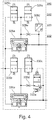
- Fig. 4 shows a schematic representation of a further embodiment of an electronic parking brake device 316, which in the embodiment according to Fig. 1 represents a possible embodiment for the electronic parking brake device 16 shown there.
- the first bistable valve unit 326 is formed here by the relay valve of the towing vehicle 326a, a first solenoid valve 326b, a second solenoid valve 326c, a pressure sensor 326d and a throttle 326e.
- the second bistable valve unit 330 is formed by the relay valve of the trailer 330a, a solenoid valve 330b, a further solenoid valve 330c and a throttle 330d.
- the valve device 332 is formed by the relay valve of the trailer 330a and a vent valve 332a.
- the parking brake device 316 is a parking brake device with a pneumatic valve in the feedback line.
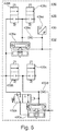
- Fig. 5 shows a further embodiment of an electronic parking brake device 416, which is a possible embodiment of the in Fig. 1 represents electronic parking brake device 16 shown.
- the first bistable valve unit 426 is formed here by the relay valve of the towing vehicle 426a, a first solenoid valve 426b, a second solenoid valve 426c, a pressure sensor 426d and a throttle 426e.
- the second bistable valve unit 430 is formed by the relay valve of the trailer 430a, a solenoid valve 430b, a further solenoid valve 430c and a throttle 430d.
- the valve device 432 is formed by the relay valve of the trailer 430a and a vent valve 432a.
- the pneumatic vent valve 432a is here, however, differently from the embodiment according to FIG Fig. 4 , where the pneumatic vent valve 332a is arranged in the feedback line for the relay valve 330a, here in the supply line for the relay valve of the trailer.
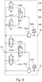
- Both versions of an electronic parking brake device 516 and 616 are embodiments with bistable valve units without feedback.
- the first bistable valve unit 526 is formed by the relay valve of the towing vehicle 526a, a solenoid valve 526b, a further solenoid valve 526c, a control valve device 526d and a pressure sensor 526e.
- the second bistable valve unit 530 comprises the relay valve of the trailer 530a, a solenoid valve 530b, a further solenoid valve 530c, a control valve 530d and a pressure sensor 530e.
- the valve device 532 is formed here by the relay valve of the trailer 530a, the solenoid valve 530c, the control valve 530d and the pressure sensor 530e.
- the first bistable valve unit 626 is formed by the relay valve of the towing vehicle 626a, a solenoid valve 626b, a further solenoid valve 626c, a control valve device 626d and a pressure sensor 626e.
- the first bistable valve unit 626 has, in contrast to that in FIG Fig. 6 embodiment shown further on a throttle 626f.
- the second bistable valve unit 630 comprises the relay valve of the trailer 630a, a solenoid valve 630b, a further solenoid valve 630c, a control valve 630d and a pressure sensor 630e. Furthermore, the embodiment according to Fig. 7 in contrast to the embodiment according to Fig. 6 further on a throttle 630f.
- the valve device 632 is formed here by the relay valve of the trailer 630a, the solenoid valve 630c, the control valve 630d, the pressure sensor 630e and the throttle 630f.
- Fig. 7 shows the parking brake device 616 in the parked state.
Description
- Die vorliegende Erfindung betrifft eine pneumatische Bremseinrichtung für ein Nutzfahrzeug mit wenigstens einem pneumatisch ansteuerbaren Federspeicherbremszylinder und mit einer elektronischen Parkbremseinrichtung.
- Pneumatische Bremseinrichtungen für Nutzfahrzeuge (z.B. Lastkraftwagen), die auch Anhänger ziehen können, sind bereits aus dem Stand der Technik bekannt. Derartige Systeme sind auch mit einer Parkbremsfunktion ausgestattet, die durch eine elektronische Parkbremseinrichtung bereitgestellt werden kann.
- Beispielsweise wird in den Vereinigten Staaten von Amerika die Parkbremsfunktion durch Einlegen von Federspeicherbremszylindern sowohl im Nutzfahrzeug bzw. Zugfahrzeug als auch im Anhänger realisiert. Dazu werden die jeweiligen Federspeicher mit einem pneumatischen Parkventil angesteuert, welche die Federspeicher direkt, ohne Verwendung eines Relaisventils, befüllt oder entlüftet. Das Parkventil weist dabei einen ersten Ventilteil für den Lastkraftwagen und einen zweiten Ventilteil für den Anhänger auf. Diese können farblich unterschiedlich ausgestaltet sein, beispielsweise dass der erste Ventilteil für das Zugfahrzeug einen gelben Betätigungsknopf und der zweite Ventilteil für den Anhänger einen roten Betätigungsknopf aufweist. Aufgrund gesetzlicher Vorschriften kann es notwendig sein, dass die Bremseinrichtung ein Zugwagenschutzventil aufweist. Das Zugwagenschutzventil verhindert ein Abfallen des ausgesteuerten Luftdrucks für die Betriebsbremse des Zugfahrzeugs bei einem Druckabfall der Betriebsbremse des Anhängerfahrzeugs.
- Hierbei wird davon ausgegangen, dass Druckluft ggf. sowohl aus der Druckluftleitung, welche dem Anhängerfahrzeug Druckluft für die Betriebsbremse bereitstellt, als auch aus der Druckluftleitung, welche dem Anhängerfahrzeug Druckluft für die Parkbremse bereitstellt, entweicht.
- Dies ist beispielsweise dann der Fall, wenn sich das Anhängerfahrzeug vom Zugfahrzeug löst und dabei beide Druckluftleitungen, welche das Zugfahrzeug und das Anhängerfahrzeug verbinden, abreißen.
- In anderen Ländern wird ein derartiges Zugwagenschutzventil nicht verwendet, stattdessen werden bistabile Ventileinheiten verwendet, wie dies beispielsweise aus der
DE 10 2008 007 877 B3 bekannt ist. - Wie dies insbesondere aus der
WO 2008/025398 A1 bekannt ist, werden Bistabil-Ventile im Zusammenhang mit der Verwendung von Zugwagen-Schutzventilen abgelehnt, und stattdessen anderweitig sichergestellt, dass auch im Falle eines Ausfalls der elektrischen Spannungsversorgung ein sicheres Abstellen des Fahrzeugs ermöglicht wird. - Weitere pneumatische Bremseinrichtungen für Nutzfahrzeuge mit einem Zugwagen-Schutzventil sind beispielsweise aus der
DE 101 32 493 A1 , derWO 00/78591 A1 WO 2009/046779 A1 und derUS 5,061,015 bekannt. - Aus der
DE 10 2005 058 799 A1 ist eine elektropneumatische Bremssteuerungseinrichtung zur Steuerung einer Feststellbremse eines Fahrzeugs mit Betriebsbremse und Feststellbremse bekannt. Dabei weist die Betriebsbremse ein Bremspedal und in Wirkverbindung mit dem Bremspedal stehende druckluftbetätigbare Bremszylinder zur Betätigung von Radbremsen auf, wobei wenigstens ein Bremszylinder als Federspeicherbremszylinder ausgebildet ist und der Federspeicher Teil des Federspeicherbremszylinders die Feststellbremse betätigt und wobei die Bremssteuerungseinrichtung derart ausgebildet ist, dass beim Ausfall der elektrischen Energieversorgung der Federspeicherteil des Federspeicherbremszylinders durch Betätigen des Bremspedals dauerhaft entlüftbar ist, um ein Parkzustand der Feststellbremse herzustellen. - Aus der
DE 10 2010 011 978 A1 ist ein elektrisch betätigbares Feststellbremssystem bekannt für eine pneumatische Bremsanlage, mit einer einen Steuerkolben aufweisenden Ventilsteuereinrichtung, wobei das Feststellbremssystem mindestens zwei Betriebszustände einnehmen kann, nämlich einen Parkzustand oder einen Fahrzeugzustand, die Betriebszustände selektiv in Abhängigkeit einer Stellung des Steuerkolbens einnehmbar sind und der Parkzustand vorliegt, wenn der Steuerkolben durch die Kraft einer in einem Federraum angeordneten Feder in eine Endlage gezwungen ist. Weiter ist dabei vorgesehen, dass aus einem Entlüftungsanschluss der Steuerventileinrichtung austretende Leckluft in den Federraum rückführbar ist. - Aus der
EP 0 976 636 A2 ist eine Druckversorgungseinrichtung für Fahrzeugdruckluftanlagen mit einem Lufttrockner, einem Mehrkreisschutzventil, das Überströmventile mit wenigstens einem Ausgang, an dem ein Ausgangsdruck anliegt, bekannt. Dabei ist vorgesehen, dass die Ausgangsdrücke der Überströmventile über einen Flansch in den Lufttrockner nachgeführt werden und dort mittels Drucksensoren in elektrische Signale wandelbar sind und der Elektronikvorrichtung zuführbar sind. - Es ist die Aufgabe der vorliegenden Erfindung, eine pneumatische Bremseinrichtung für ein Nutzfahrzeug der eingangs genannten Art in vorteilhafter Weise weiterzubilden, insbesondere dahingehend, dass diese vergleichsweise einfach und sicher aufgebaut ist und im Vergleich zu den aus dem Stand der Technik bekannten Bremseinrichtungen zusätzliche Sicherheitsvorkehrungen aufweisen kann und betriebsstabil im Fahrzustand als auch im Bremszustand ist.
- Diese Aufgabe wird erfindungsgemäß gelöst durch eine pneumatische Bremseinrichtung mit den Merkmalen des Anspruchs 1.
- Danach ist vorgesehen, dass eine pneumatische Bremseinrichtung für ein Nutzfahrzeug mit wenigstens einem pneumatisch ansteuerbaren Federspeicher für eine Parkbremse des Nutzfahrzeugs und mit wenigstens einer elektronischen Parkbremseinrichtung versehen ist, weiter mit wenigstens einer Steuerelektronik, wenigstens einer ersten bistabilen Ventileinheit und mit wenigstens einer zweiten bistabilen Ventileinheit, wenigstens weiter mit einer ersten Ventileinrichtung, die derart verschaltbar ist, dass bei einem Absinken des Systemdrucks zur Versorgung einer Parkbremse eines Anhängers des Zugfahrzeugs die Parkbremse des Anhängers aktivierbar ist, und mit einem Zugfahrzeug-Schutzventil.
- Die Erfindung basiert auf dem Grundgedanken, durch die Verwendung von bistabilen Ventileinheiten eine Funktionalität in einer pneumatischen Bremseinrichtung für ein Nutzfahrzeug bereitzustellen, so dass auch ohne Elektrizität die aktuelle Stellung der Bremseinrichtung, also Fahren oder Parken beibehalten wird. Mittels dieser beiden bistabilen Ventileinheiten sollen dann die Federspeicher des Nutzfahrzeugs (Zugfahrzeugs) und auch des Anhängers belüftet oder entlüftet werden können. Unter dem Begriff bistabile Ventileinheit im Sinne der Erfindung ist insbesondere eine pneumatisch und/oder elektrisch/elektronisch ansteuerbare Ventileinheit zu verstehen, nicht aber ein Steuerschalter, der pneumatisch oder elektrisch eine Bremseinrichtung bzw. eine Parkbremseinrichtung ansteuert. Zusätzlich ist eine Ventileinrichtung vorgesehen, mittels derer bei belüfteten Federspeichern des Lastkraftwagens (Zugfahrzeug) die Federspeicher des Anhängers entlüftet werden können. Dies beinhaltet insbesondere auch eine Notbremse-Funktionalität, die beim Absinken des Systemdrucks für den Anhänger unter einen bestimmten Schwellenwert die Parkbremse des Anhängers aktiviert (Emergency Braking). Des Weiteren ist ein Zugwagen-Schutzventil vorgesehen, mittels dessen ein Abfallen des ausgesteuerten Luftdrucks für die Betriebsbremse des Zugfahrzeugs beim Druckabfall des ausgesteuerten Luftdrucks für die Betriebsbremse des Anhängers verhindert wird. Mit anderen Worten ist das Zugwagen-Schutzventil derart angeordnet, dass die Druckluftverbindung zwischen Zugfahrzeug und Anhängerfahrzeug notfalls unterbrochen werden kann.
- Des Weiteren ist erfindungsgemäß vorgesehen, dass mittels der ersten bistabilen Ventileinheit die Parkbremse des Zugfahrzeugs und mittels der zweiten bistabilen Ventileinheit die Parkbremse des Anhängers ansteuerbar ist. Hierdurch wird ein einfacher Aufbau der Parkbremseinrichtung möglich.
- Dadurch, dass eine erste bistabile Ventileinheit für das Zugfahrzeug und eine zweite bistabile Ventileinheit für den Anhänger vorgesehen ist, wird insgesamt ein stabiler und robuster Aufbau der Bremseinrichtung bzw. der Parkbremseinrichtung bereitgestellt. Denn durch die Verwendung der bistabilen Ventileinheiten wird es möglich, die jeweils aktuelle Stellung auch ohne Elektrizität beibehalten zu können, so dass stabile Betriebszustände möglich sind, hier insbesondere Parken und Fahren.
- Das Zugfahrzeug-Schutzventil kann Bestandteil der elektronischen Parkbremseinrichtung sein.
- Alternativ kann vorgesehen sein, dass das Zugfahrzeug-Schutzventil Bestandteil einer Luftaufbereitungsanlage der pneumatischen Bremseinrichtung ist.
- Die Ventileinrichtung kann wenigstens einen Drucksensor aufweisen, mittels dessen ein Druckabfall des Systemdrucks unter einen vorgegebenen Schwellenwert ermittelbar und ein Signal generierbar ist, anhand dessen mittels der Steuerelektronik die Parkbremse des Anhängers aktivierbar ist. Hierdurch kann einfach und zuverlässig festgestellt werden, ob es zu einem Absinken des Systemdrucks im Anhänger gekommen ist und dort der Druck unter einen bestimmten Schwellenwert gefallen ist. Sodann kann die Parkbremse des Anhängers aktiviert werden. Diese Funktion wird auch Emergency Braking genannt.
- Des Weiteren kann vorgesehen sein, dass die Ventileinrichtung wenigstens ein pneumatisches Ventil aufweist, mittels dessen die Parkbremse des Anhängers aktivierbar ist. Dadurch wird es möglich, unabhängig von der Bremseinrichtung des Zugfahrzeugs die Parkbremse des Anhängers gesondert zu aktivieren.
- Die erste und/oder zweite bistabile Ventileinheit kann ein bistabiles Ventil mit Rückkopplung umfassen. Durch die Rückkopplung lässt sich beispielsweise erreichen, dass eine Notbremsfunktion für den Anhänger integriert werden kann.
- In diesem Zusammenhang kann vorgesehen sein, dass das bistabile Ventil mit Rückkopplung ein Relaisventil ist. Insbesondere kann hier vorgesehen sein, dass eine bistabile Ventilfunktion durch die Nutzung eines Relaisventils als bistabiles Ventil erreicht wird.
- Des Weiteren kann vorgesehen sein, dass für die erste bistabile Ventileinheit das Relaisventil das Relaisventil des Nutzfahrzeugs ist. Hierdurch wird es möglich, ein ohnehin vorhandenes Ventil wie das Relaisventil des Zugfahrzeugs für die Ausbildung der Bistabilität und der entsprechenden Funktionalität, die durch eine bistabile Ventileinheit erreicht werden soll, zu erreichen.
- Außerdem kann vorgesehen sein, dass für die zweite bistabile Ventileinheit das Relaisventil das Relaisventil des Anhängers ist. Auch hier gilt, dass durch einen derartigen Aufbau ein bereits vorhandenes Ventil verwendet werden kann, wodurch der Aufbau insgesamt vereinfacht wird.
- Des Weiteren kann vorgesehen sein, dass die bistabile Ventileinheit weiter eine Drossel aufweist.
- Mittels der Drossel kann der Volumenstrom der Rückkopplung vom Ausgang des Relaisventils zu dessen Steuerseite begrenzt werden. Hierdurch wird es möglich, die Schaltpunkte des Relaisventils besser einstellen zu können.
- Des Weiteren kann vorgesehen sein, dass die bistabile Ventileinheit weiter einen Drucksensor aufweist. Hierdurch wird es möglich, beispielsweise in Abhängigkeit der ermittelten Druckwerte mittels des Drucksensors ein gewisses Schaltverhalten der bistabilen Ventileinheit einzustellen und eine entsprechende Funktionalität bereitzustellen.
- Des Weiteren kann vorgesehen sein, dass die bistabile Ventileinheit weiter wenigstens zwei Magnetventile aufweist. Mittels einer Verschaltung mit zwei Magnetventilen wird es beispielsweise möglich, z.B. das Relaisventil entsprechend anzusteuern und in einer einfachen und zuverlässigen Art und Weise eine Bistabilität herbeizuführen.
- Die Ventileinrichtung kann durch das Relaisventil des Anhängers mit ausgebildet sein.
- Denkbar ist in diesem Zusammenhang auch, dass die Ventileinrichtung durch das Relaisventil des Anhängers und zwei Magnetventile ausgebildet wird. Der Begriff Ventileinheit ist hier insbesondere dahingehend zu verstehen, dass mehrere Komponenten einer pneumatischen Bremseinrichtung funktional miteinander zusammenwirken. Durch das Zusammenwirken des Relaisventils des Anhängers sowie der Magnetventile wird es möglich, die Parkbremseinrichtung des Anhängers, d.h. die Federspeicher des Anhängers anzusteuern und dies gesondert von der Parkbremseinrichtung des Zugfahrzeugs. Dies bedeutet, dass es auch bei entlüfteten Federspeichern des Zugfahrzeugs möglich ist, die Federspeicher des Anhängers belüften zu können.
- Des Weiteren kann vorgesehen sein, dass die Ventileinrichtung das Relaisventils des Anhängers, wenigstens zwei weitere Magnetventile sowie einen Drucksensor und eine Drossel aufweist. Auch hier ist der Begriff Ventileinrichtung dahingehend zu verstehen, dass für eine bestimmte Funktionalität mehrere Komponenten miteinander zusammenwirken. Durch das Zusammenwirken des Relaisventils des Anhängers, wenigstens weiterer zweier Magnetventile sowie eines Drucksensors wird es möglich, zum einen ein Absinken des Systemdrucks für die Parkbremse des Anhängers und einen bestimmten Schwellenwert zu detektieren und in Abhängigkeit hiervon, insbesondere im Zusammenwirken mit der Steuerelektronik der pneumatischen Bremseinrichtung das Relaisventil und die weiteren zwei Magnetventile derart zu schalten, dass die Parkbremse des Anhängers aktiviert werden kann, was als Notbremse genutzt werden kann. Mittels des Drucksensors kann insbesondere die Zuleitung stromabwärts des Relaisventils des Anhängers zu den Federspeichern des Anhängers überwacht werden.
- Die Ventileinrichtung kann ferner das Relaisventil des Anhängers und wenigstens ein Entlüftungsventil aufweisen. Über die Entlüftung wird es möglich, die Federspeicher des Anhängers mittels des Entlüftungsventils entlüften zu können.
- Alternativ ist auch denkbar, dass die erste und/oder zweite bistabile Ventileinheit ein bistabiles Ventil ohne Rückkopplung umfasst.
- Insbesondere ist in diesem Zusammenhang denkbar, dass das bistabile Ventil der bistabilen Ventileinheit ohne Rückkopplung ein bistabiles 3/2-Wegeventil ist, das ein Relaisventil ansteuert.
- Das bistabile Ventil kann ein Relaisventil sein.
- Insbesondere kann vorgesehen sein, dass die bistabile Ventileinheit weiter das Relaisventil des Zugfahrzeugs umfasst. Denkbar ist in diesem Zusammenhang auch, dass das Relaisventil des Zugfahrzeugs sowie ein weiteres Steuerventil gemeinsam in funktionaler Hinsicht die bistabile Ventileinheit ausbilden.
- Des Weiteren kann vorgesehen sein, dass für die zweite bistabile Ventileinheit das Relaisventil das Relaisventil des Anhängers ist.
- Die erste und/oder zweite bistabile Ventileinheit kann weiter eine Drossel aufweisen. Hierdurch wird es möglich, die erste und/oder zweite bistabile Ventileinheit hinsichtlich ihres Schaltpunkts besser einstellen zu können.
- Darüber hinaus kann vorgesehen sein, dass die bistabile Ventileinheit weiter einen Drucksensor aufweist. Mittels des Drucksensors kann beispielsweise ein Druckabfall im Anhänger detektiert werden und mittels entsprechender Ventile, insbesondere Magnetventile, sowie des bzw. der Relaisventile kann sodann eine Schaltung herbeigeführt werden, mittels derer die Federspeicher z.B. des Anhängers entlüftet werden können.
- Grundsätzlich ist denkbar, dass mittels eines Drucksensors ein Druckabfall registriert wird, worauf die Federspeicher des Anhängers mittels eines elektrischen Signals und mittels wenigstens eines Magnetventils entlüftet werden.
- Denkbar ist in diesem Zusammenhang insbesondere, dass die bistabile Ventileinheit weiter wenigstens zwei Magnetventile aufweist.
- Alternativ und/oder zusätzlich kann auch eine Lösung vorgesehen sein, bei der mittels eines pneumatischen Ventils die Federspeicher des Anhängers entlüftet werden, wenn mittels der zweiten Ventileinrichtung ein Absinken des Systemdrucks für den Anhänger unter einen bestimmten Schwellenwert detektiert wird, so dass die Parkbremse des Anhängers aktiviert wird (Notbremsung).
- Die Ventileinrichtung kann durch das Relaisventil des Anhängers mit ausgebildet sein.
- Weiter kann vorgesehen sein, dass die Ventileinrichtung weiter wenigstens ein Magnetventil und einen Drucksensor aufweist. Außerdem kann die Ventileinrichtung auch weiter eine Drossel aufweisen.
- Weitere Einzelheiten und Vorteile der Erfindung sollen nun anhand eines in den Zeichnungen dargestellten Ausführungsbeispiels näher erläutert werden.
- Es zeigen:
- Fig. 1
- eine schematische Zeichnung eines erfindungsgemäßen Ausführungsbeispiels einer pneumatischen Bremseinrichtung für ein Nutzfahrzeug;
- Fig. 2
- eine schematische Darstellung einer ersten Ausführungsform einer elektronischen Parkbremseinrichtung;
- Fig. 3
- eine schematische Darstellung einer zweiten Ausführungsform einer elektronischen Parkbremseinrichtung;
- Fig. 4
- eine schematische Darstellung einer dritten Ausführungsform einer elektronischen Parkbremseinrichtung;
- Fig. 5
- eine schematische Darstellung einer vierten Ausführungsform einer elektronischen Parkbremseinrichtung;
- Fig. 6
- eine schematische Darstellung einer fünften Ausführungsform einer elektronischen Parkbremseinrichtung; und
- Fig. 7
- eine schematische Darstellung einer sechsten Ausführungsform einer elektronischen Parkbremseinrichtung.
-
Fig. 1 zeigt eine pneumatische Bremseinrichtung 10 für ein Nutzfahrzeug, beispielsweise einen Lastkraftwagen (nicht näher dargestellt). - Die pneumatische Bremseinrichtung 10 weist mehrere pneumatisch ansteuerbare Federspeicher 12 für die Parkbremse des Nutzfahrzeugs, auch Zugfahrzeug genannt, sowie pneumatisch ansteuerbare Bremszylinder 13 der Betriebsbremse für die Vorderachse als auch für die Hinterachse bzw. die Hinterachsen auf. Im gezeigten Ausführungsbeispiel sind an der Hinterachse der Federspeicher 12 und der Bremszylinder 13 als Federspeicherbremszylinder ausgeführt, mit dem Federspeicher 12 für die Parkbremsfunktion und mit dem Bremszylinder 13 für die Betriebsbremse.
- Weiter ist ein Kompressor 14 vorgesehen, der mit einer elektronischen Parkbremseinrichtung 16 in Verbindung steht.
- Weiter ist ein Parkventilschaltelement 18 vorgesehen, das einen ersten Schalter 20 und einen zweiten Schalter 22 aufweisen kann.
- Die elektronische Parkbremseinrichtung 16 weist eine Steuerelektronik 24, eine erste bistabile Ventileinheit 26, eine Luftaufbereitung 28 sowie eine zweite bistabile Ventileinheit 30 und eine Ventileinrichtung 32 auf. Stromabwärts der elektronischen Parkbremseinrichtung 16 sind ein erster Druckluftbehälter 34 und ein zweiter Druckluftbehälter 36 vorgesehen.
- Ferner ist das Fußbremsventil 38 der Bremseinrichtung 10 gezeigt. Darüber hinaus ist ein Zugfahrzeug-Schutzventil 40 vorgesehen.
- Die pneumatische Bremseinrichtung 10 weist weiter einen Anschluss 42 zur Parkbremse eines Anhängers des Nutzfahrzeugs sowie einen weiteren gesonderten Anschluss 44 zur Betriebsbremse des Anhängers auf.
- Der Kompressor 14 ist über eine Leitung 46 mit der Parkbremseinrichtung 16 verbunden. Stromabwärts der Parkbremseinrichtung 16 schließen sich an die Luftaufbereitung 28 Leitungen 48 und 50 an, die zum Behälter 34 bzw. Behälter 36 führen.
- Das Fußbremsventil 38 wird über die Leitung 52 mit dem ersten Behälter 34 verbunden und über die Leitung 54 mit dem zweiten Behälter 36. Stromabwärts des Fußbremsventils 38 schließen die Versorgungsleitungen und Leitungszweige zu den Bremszylindern bzw. Federspeicherbremszylindern 12 an. Das Zugfahrzeug-Schutzventil 40 ist ebenfalls an diese Leitung angeschlossen, wobei die Druckluft, die von diesem Leitungszweig zum Zugfahrzeug-Schutzventil 40 strömt und sodann weiter zu dem Anschluss 44 für die Betriebsbremse des Anhängers bzw. zum Anschluss 42 für den Federspeicher des Anhängers strömt, zunächst durch das Zugfahrzeug-Schutzventil 40 hindurch geleitet werden muss. Das Fußbremsventil 38 ist über eine Leitung 56 mit dem Zugfahrzeug-Schutzventil 40 verbunden.
- Die erste bistabile Ventileinheit 26 ist über eine Leitung 58 mit den Federspeicherbremszylindern der Hinterachse verbunden.
- Die Ventileinrichtung 32 ist über eine Leitung 60 mit dem Anschluss 42 für die Federspeicher des Anhängers verbunden.
- Die Steuerelektronik 24 ist mit dem Parkventilschaltelement 18 verbunden, wobei eine erste Signalleitung 62 vom ersten Schalter mit der Steuerelektronik 24 verbunden ist und eine zweite Leitung 64 mit der Elektronik 24 verbunden ist, die eine Verbindung mit dem zweiten Schalter des Parkventilschaltelements 18 herstellt.
- Die pneumatische Bremseinrichtung 10 weist somit mehrere pneumatisch ansteuerbare Federspeicher 12 für die Parkbremse des Nutzfahrzeugs auf sowie eine elektronische Parkbremseinrichtung 16 auf, die selbst wiederum eine Steuerelektronik 24 aufweist.
- Darüber hinaus ist Bestandteil der elektronischen Parkbremseinrichtung 16 eine erste bistabile Ventileinheit 26 zum Belüften bzw. Entlüften der Federspeicher 12 der Parkbremse des Zugfahrzeugs, sowie eine zweite bistabile Ventileinheit 30 zum Belüften bzw. Entlüften der Federspeicherbremszylinder des Anhängers, so dass mittels der zweiten bistabilen Ventileinheit 30 die Federspeicher der Parkbremseinrichtung des Anhängers des Zugfahrzeugs belüftbar sind sowie eine Ventileinrichtung 32, die derart verschaltbar ist, dass bei einem Absinken des Systemdrucks für die Parkbremse des Anhänger des Zugfahrzeugs die Parkbremseinrichtung des Anhängers aktivierbar ist.
- Mittels der ersten bistabilen Ventileinheit 26 ist die Parkbremse des Zugfahrzeugs mit den Federspeichern 12 und mit der zweiten bistabilen Ventileinheit 30 die Parkbremse des Anhängers ansteuerbar, auch über die Ventileinrichtung 32. Über die Leitung 60 ist die zweite bistabile Ventileinheit 30 mit dem Anschluss 42 zu den Federspeicherbremszylindern der Parkbremse des Anhängers verbunden.
- Das Zugfahrzeug-Schutzventil 40 ist hier Bestandteil der Bremseinrichtung, kann jedoch alternativ auch als Bestandteil der elektronischen Parkbremseinrichtung 16 ausgeführt sein oder als Bestandteil der Luftaufbereitungsanlage 28 der pneumatischen Bremseinrichtung 10.
- Die Funktion der pneumatischen Bremseinrichtung 10 ist hier wie folgt:
Die elektronische Parkbremseinrichtung 16 umfasst eine Steuerelektronik 24 und verarbeitet die Steuersignale, die vom elektronischen Parkventil 18 übermittelt werden. - Darüber hinauf findet ein Informationsaustausch mit der Steuerelektronik 24 des Lastkraftwagens statt (nicht im Detail gezeigt).
- Die erste bistabile Ventileinheit 26 und die zweite bistabile Ventileinheit 30 behalten auch ohne Elektrizität jeweils ihre aktuelle Stellung bei. Diese Ventile können direkt oder über ein oder mehrere Relaisventile gemeinsam die Federspeicherbremszylinder 12 des Zugfahrzeugs oder des Anhängers (über die Leitung 60 und den Anschluss 42) belüften oder entlüften.
- Die zweite bistabile Ventileinheit 30 kann beim entlüfteten Federspeicher des Lastkraftwagens die Federspeicher des Anhängers belüften. Dies ist beispielsweise für die Trailertest-Funktion notwendig.
- Die Ventileinrichtung 32 kann bei belüfteten Federspeichern des Lastkraftwagens die Federspeicher des Anhängers entlüften, und zwar über die Leitung 60 und den Anschluss 42. Dies beinhaltet insbesondere eine Notbremse-Funktionalität, die beim Absinken des Systemdrucks für den Anhänger unter einen bestimmten Schwellenwert die Parkbremse des Anhängers aktiviert (sog. Emergency Braking Funktion).
- Die Ansteuerung der Bremseinrichtung 10 über das Parkventilschaltelement 18 mit den Schaltern 20 und 22 kann für die folgenden Betriebszustände wie folgt erfolgen:
Im Fahrzustand sind beispielsweise der Schalter 20 zur Betätigung der Parkbremseinrichtung des Zugfahrzeugs und der Schalter 22 zur Betätigung der Parkbremseinrichtung des Anhängers gedrückt (alternativ auch andere Betätigungsstellungen denkbar). - Dadurch wird die erste bistabile Ventileinheit 26 und die zweite bistabile Ventileinheit 30 durchgeschaltet während die Ventileinrichtung 32 nicht durchgeschaltet sind.
- Dadurch sind sowohl die Federspeicherbremszylinder 12 des Zugfahrzeugs als auch die Federspeicherbremszylinder 12 des Anhängers freigegeben.
- Im Parkzustand sind die beiden Schalter 20 und 22 gezogen, so dass die erste bistabile Ventileinheit 26 und die zweite bistabile Ventileinheit 30 und die Ventileinrichtung 32 nicht durchgeschaltet sind.
- Somit sind die Federspeicherbremszylinder 12 des Zugfahrzeugs derart geschaltet, dass die Bremsen des Zugfahrzeugs aktiviert sind. Dies gilt auch für die Federspeicherbremszylinder 12 des Anhängers, die ebenfalls derart geschaltet sind, dass die Bremsen des Anhängers aktiviert sind.
- Für die Befüllung des Anhängers kann ein Betriebszustand genutzt werden, bei dem die Parkbremse des Zugfahrzeugs aktiviert ist, die des Anhängers aber nicht. Das kann auch auch genutzt werden, um den sogenannten Trailer-Test durchzuführen. Es ist der Schalter 20 gezogen und der Schalter 22 eingedrückt (aktiviert). Dadurch ist die erste bistabile Ventileinheit 26 nicht durchgeschaltet, aber die zweite bistabile Ventileinheit 30. Die Ventileinrichtung 32 ist ebenfalls nicht durchgeschaltet.
- Dies hat zur Folge, dass die Federspeicher 12 der Parkbremse des Zugfahrzeugs derart geschaltet sind, dass das Zugfahrzeug gebremst ist und die Federspeicher der Parkbremse des Anhängers derart geschaltet sind, dass diese freigegeben sind.
- Bei dem Betriebszustand Anhänger Parken (Bremsung nur über Anhänger), ist der Schalter 20 gedrückt und der Schalter 22 gezogen.
- Folglich ist die erste bistabile Ventileinheit 26 aktiviert, die zweite bistabile Ventileinheit 30 nicht aktiviert und die Ventileinrichtung 32 nicht aktiviert.
- Dies hat zur Folge, dass die Federspeicher 12 der Parkbremse des Zugfahrzeugs derart geschaltet sind, dass das Zugfahrzeug ungebremst ist und die Federspeicher der Parkbremse des Anhängers aktiviert sind, so dass der Anhänger gebremst wird.
- Bei dem Betriebszustand Notbremsung, der automatisch aktiviert wird, nämlich dann, wenn ein Absinken des Systemdrucks für die Parkbremse des Anhänger detektiert wird, befindet sich üblicherweise das Fahrgespann, bestehend aus Zugfahrzeug und Anhänger, im Fahrzustand, d.h. der Schalter 20 und der Schalter 22 sind beide gedrückt. Abweichend zum vorbeschriebenen Fahrzustand, bei dem die erste bistabile Ventileinheit 26 und die zweite bistabile Ventileinheit 30 durchgeschaltet sind, jedoch nicht die Ventileinrichtung 32, wird nun die Ventileinrichtung 32 aktiviert und die zweite bistabile Ventileinheit 30 vom durchgeschalteten Zustand in den nicht durchgeschalteten Zustand überführt.
- Dadurch wird erreicht, dass die Federspeicher12 der Parkbremse des Zugfahrzeugs weiterhin derart geschaltet sind, dass das Zugfahrzeug ungebremst ist, jedoch die Federspeicherbremszylinder des Anhängers derart geschaltet werden, dass sie vom ungebremsten Zustand in den gebremsten Zustand geschaltet werden.
- Die
Figuren 2 bis 5 betreffen mögliche Ausführungsformen der elektronischen Parkbremseinrichtung mit Rückkopplung, wie sie bei dem inFig. 1 gezeigten Ausführungsbeispiel einer pneumatischen Bremseinrichtung 10 eingesetzt werden können. - Jede der gezeigten Ausführungsformen der elektronischen Parkbremseinrichtungen 116 (
Fig. 2 ), 216 (Fig. 3 ), 316 (Fig. 4 ) und 416 (Fig. 5 ) ist als mögliche Ausführungsform der elektronischen Parkbremseinrichtung 16, wie grob schematisch inFig. 1 gezeigt, zu verstehen. -
Fig. 2 zeigt eine erste mögliche Ausführungsform einer elektronischen Parkbremseinrichtung 116 mit einer bistabilen Ventileinheit 126 mit Rückkopplung. - Die bistabile Ventileinheit 126 mit Rückkopplung besteht aus den funktional zusammen wirkenden Relaisventil des Zugfahrzeugs 126a, einem Magnetventil 126b, einem weiteren Magnetventil 126c, einem Drucksensor 126d sowie einer Drossel 126e.
- Die zweite bistabile Ventileinheit 130 besteht aus den funktional zusammen wirkenden Relaisventil des Anhängers 130a, einem Magnetventil 130b, einem weiteren Magnetventil 130c, einem Drucksensor 130d und einer Drossel 130e.
- Die Ventileinrichtung 132 ist funktional ausgebildet durch das Relaisventil des Anhägers 130a, das Magnetventil 130c, den Drucksensor 130d sowie die Drossel 130e.
- Sowohl für die erste bistabile Ventileinheit 126, die zweite bistabile Ventileinheit 130 und die Ventileinrichtung 132 dienen die Magnetventile, der Drucksensor sowie die Drosseln zur Ansteuerung bzw. Einstellung der Relaisventile, der Einstellung der Schaltpunkte sowie zur Gewährleistung einer bistabilen Funktion.
-
Fig. 3 zeigt in schematischer Ansicht ein weiteres Ausführungsbeispiel einer elektronischen Parkbremseinrichtung 216, die eine mögliche Ausführungsform der inFig. 1 gezeigten Parkbremseinrichtung 16 darstellt. - Die elektronische Parkbremseinrichtung 216 gemäß
Fig. 3 ist eine Ausführungsform mit Drucksensor, aber ohne Zusatzelemente. - Die erste bistabile Ventileinheit 226 wird ausgebildet durch das Relaisventil des Zugfahrzeugs 226a, ein Magnetventil 226b, ein weiteres Magnetventil 226c, einen Drucksensor 226d und eine Drossel 226e.
- Die zweite bistabile Ventileinheit 230 wird ausgebildet durch das Relaisventil des Anhängers 230a, ein Magnetventil 230b, ein weiteres Magnetventil 230c sowie eine Drossel 230d ausgebildet.
- Die Ventileinrichtung 232 wird hier lediglich ausgebildet durch durch das Relaisventil des Anhängers 230a und die Drossel 230d.
- Auch hier dienen die Magnetventile, der Drucksensor bzw. die Drossel dazu, die bistabile Funktion, die Schaltcharakteristik sowie die Schaltpunkte zu definieren bzw. zu gewährleisten.
-
Fig. 4 zeigt in schematischer Darstellung ein weiteres Ausführungsbeispiel einer elektronischen Parkbremseinrichtung 316, die in dem Ausführungsbeispiel gemäßFig. 1 eine mögliche Ausführungsform für die dort gezeigte elektronische Parkbremseinrichung 16 darstellt. - Die erste bistabile Ventileinheit 326 ist hier durch das Relaisventil des Zugfahrzeugs 326a, ein erstes Magnetventil 326b, ein zweites Magnetventil 326c, einen Drucksensor 326d sowie eine Drossel 326e ausgebildet.
- Die zweite bistabile Ventileinheit 330 wird ausgebildet durch das Relaisventil des Anhängers 330a, ein Magnetventil 330b, ein weiteres Magnetventil 330c sowie eine Drossel 330d.
- Die Ventileinrichtung 332 wird ausgebildet durch das Relaisventil des Anhängers 330a sowie ein Entlüftungsventil 332a.
- Bei der Parkbremseinrichtung 316 gemäß
Fig. 4 handelt es sich um eine Parkbremseinrichtung mit einem pneumatischen Ventil in der Rückkopplungs-Leitung. -
Fig. 5 zeigt eine weitere Ausführungsform einer elektronischen Parkbremseinrichtung 416, die eine mögliche Ausführungsform der inFig. 1 gezeigten elektronischen Parkbremseinrichtung 16 darstellt. - Dabei handelt es sich um eine Ausführungsform mit einem pneumatischen Ventil in der Versorgungsleitung.
- Die erste bistabile Ventileinheit 426 ist hier durch das Relaisventil des Zugfahrzeugs 426a, ein erstes Magnetventil 426b, ein zweites Magnetventil 426c, einen Drucksensor 426d sowie eine Drossel 426e ausgebildet.
- Die zweite bistabile Ventileinheit 430 wird ausgebildet durch das Relaisventil des Anhängers 430a, ein Magnetventil 430b, ein weiteres Magnetventil 430c sowie eine Drossel 430d.
- Die Ventileinrichtung 432 wird ausgebildet durch das Relaisventil des Anhängers 430a sowie ein Entlüftungsventil 432a.
- Das pneumatische Entlüftungsventil 432a befindet sich hier jedoch abweichend zum Ausführungsbeispiel gemäß
Fig. 4 , wo das pneumatische Entlüftungsventil 332a in der Rückkopplungsleitung für das Relaisventil 330a angeordnet ist, hier in der Versorgungsleitung für das Relaisventil des Anhängers. - In den
Figuren 6 und7 sind Ausführungsformen einer elektronischen Parkbremseinrichtung 516 (Fig. 6 ) sowie einer elektronischen Parkbremseinrichtung 616 (Fig. 7 ) gezeigt. - In beiden Fällen können diese Ausführungsformen eine mögliche Ausgestaltung der in
Fig. 1 gezeigten elekronischen Parkbremseinrichtung 16 sein. - Beide Ausführungen einer elektronischen Parkbremseinrichtung 516 bzw. 616 sind Ausführungsformen mit bistabilen Ventileinheiten ohne Rückkopplung.
- Bei der elektronischen Parkbremseinrichtung 516 gemäß
Fig. 6 wird die erste bistabile Ventileinheit 526 ausgebildet durch das Relaisventil des Zugfahrzeugs 526a, ein Magnetventil 526b, ein weiteres Magnetventil 526c, ein Steuerventileinrichtung 526d sowie einen Drucksensor 526e. - Die zweite bistabile Ventileinheit 530 umfasst das Relaisventil des Anhängers 530a, ein Magnetventil 530b, ein weiteres Magnetventil 530c, ein Steuerventil 530d sowie einen Drucksensor 530e.
- Die Ventileinrichtung 532 ist hier gebildet durch das Relaisventil des Anhängers 530a, das Magnetventil 530c, das Steuerventil 530d sowie den Drucksensor 530e.
- Bei der elektronischen Parkbremseinrichtung 616 gemäß
Fig. 7 wird die erste bistabile Ventileinheit 626 ausgebildet durch das Relaisventil des Zugfahrzeugs 626a, ein Magnetventil 626b, ein weiteres Magnetventil 626c, ein Steuerventileinrichtung 626d sowie einen Drucksensor 626e. Außerdem weist die erste bistabile Ventileinheit 626 in Abgrenzung gegenüber der inFig. 6 gezeigten Ausführungsform weiter eine Drossel 626f auf. - Die zweite bistabile Ventileinheit 630 umfasst das Relaisventil des Anhängers 630a, ein Magnetventil 630b, ein weiteres Magnetventil 630c, ein Steuerventil 630d sowie einen Drucksensor 630e. Des Weiteren weist die Ausführungsform gemäß
Fig. 7 in Abgrenzung zur Ausführungsform gemäßFig. 6 weiter eine Drossel 630f auf. - Die Ventileinrichtung 632 ist hier gebildet durch das Relaisventil des Anhängers 630a, das Magnetventil 630c, das Steuerventil 630d, den Drucksensor 630e sowie die Drossel 630f.
-
Fig. 7 zeigt die Parkbremseinrichtung 616 im Parkzustand. -
- 10
- pneumatische Bremseinrichtung
- 12
- Federspeicher
- 13
- Bremszylinder
- 14
- Kompressor
- 16
- elektronische Parkbremseinrichtung
- 18
- Parkventilschaltelement
- 20
- erster Schalter
- 22
- zweiter Schalter
- 24
- Steuerelektronik
- 26
- erste bistabile Ventileinheit
- 28
- Luftaufbereitung
- 30
- zweite bistabile Ventileinheit
- 32
- Ventileinrichtung
- 34
- erster Druckluftbehälter
- 36
- zweiter Druckluftbehälter
- 38
- Fußbremsventil
- 40
- Zugfahrzeug-Schutzventil
- 42
- Anschluss
- 44
- gesonderter Anschluss
- 46
- Leitung
- 48
- Leitung
- 50
- Leitung
- 52
- Leitung
- 54
- Leitung
- 56
- Leitung
- 58
- Leitung
- 60
- Leitung
- 62
- erste Signalleitung
- 64
- zweite Signalleitung
- 116
- elektronische Parkbremseinrichtung
- 126
- erste bistabile Ventileinheit
- 126a
- Relaisventil
- 126b
- Magnetventil
- 126c
- Magnetventil
- 126d
- Drucksensor
- 126e
- Drossel
- 130
- zweite bistabile Ventileinheit
- 130a
- Relaisventil des Anhängers
- 130b
- erstes Magnetventil
- 130c
- zweites Magnetventil
- 130d
- Drucksensor
- 130e
- Drossel
- 132
- Ventileinrichtung
- 132a
- Magnetventil
- 132b
- Drucksensor
- 216
- elektronische Parkbremseinrichtung
- 226
- erste bistabile Ventileinheit
- 226a
- Relaisventil
- 226b
- Magnetventil
- 226c
- Magnetventil
- 226d
- Drucksensor
- 226e
- Drossel
- 230
- zweite bistabile Ventileinheit
- 230a
- Relaisventil des Anhängers
- 230b
- erstes Magnetventil
- 230c
- zweites Magnetventil
- 230d
- Drossel
- 232
- Ventileinrichtung
- 232a
- Magnetventil
- 232b
- Drucksensor
- 316
- elektronische Parkbremseinrichtung
- 326
- erste bistabile Ventileinheit
- 326a
- Relaisventil des Zugfahrzeugs
- 326b
- Magnetventil
- 326c
- Magnetventil
- 326d
- Drucksensor
- 326e
- Drossel
- 330
- zweite bistabile Ventileinheit
- 330a
- Relaisventil
- 330b
- Magnetventil
- 330c
- Magnetventil
- 330d
- Drossel
- 332
- Ventileinrichtung
- 332a
- Entlüftungsventil
- 416
- elektronische Parkbremseinrichtung
- 426
- erste bistabile Ventileinheit
- 426a
- Relaisventil des Zugfahrzeugs
- 426b
- Magnetventil
- 426c
- Magnetventil
- 426d
- Drucksensor
- 426e
- Drossel
- 430
- zweite bistabile Ventileinheit
- 430a
- Relaisventil
- 430b
- Magnetventil
- 430c
- Magnetventil
- 430d
- Drossel
- 432
- Ventileinrichtung
- 432a
- Entlüftungsventil
- 516
- elektronische Parkbremseinrichtung
- 526
- erste bistabile Ventileinheit
- 526a
- Relaisventil
- 526b
- Magnetventil
- 526c
- Magnetventil
- 526d
- Steuerventileinrichtung
- 526e
- Drucksensor
- 530
- zweite bistabile Ventileinheit
- 530a
- Relaisventil
- 530b
- Magnetventil
- 530c
- Magnetventil
- 530d
- Steuerventil
- 530e
- Drucksensor
- 532
- Ventileinrichtung
- 616
- elektronische Parkbremseinrichtung
- 626
- erste bistabile Ventileinheit
- 626a
- Relaisventil
- 626b
- Magnetventil
- 626c
- Magnetventil
- 626d
- Steuerventileinrichtung
- 626e
- Drucksensor
- 626f
- Drossel
- 630
- zweite bistabile Ventileinheit
- 630a
- Relaisventil
- 630b
- Magnetventil
- 630c
- Magnetventil
- 630d
- Steuerventil
- 630e
- Drucksensor
- 630f
- Drossel
- 632
- Ventileinrichtung
Claims (25)
- Pneumatische Bremseinrichtung (10) für ein Nutzfahrzeug mit wenigstens einem pneumatisch ansteuerbaren Federspeicher (12) für eine Parkbremse des Nutzfahrzeugs mit einer elektronischen Parkbremseinrichtung (16), mit wenigstens einer Steuerelektronik (24), wenigstens einer ersten bistabilen Ventileinheit (26) und wenigstens einer zweiten bistabilen Ventileinheit (30), wenigstens eine Ventileinrichtung (32), die derart verschaltbar ist, dass bei einem Absinken des Systemdrucks zur Versorgung einer Parkbremse eines Anhängers des Zugfahrzeugs die Parkbremse des Anhängers aktivierbar ist, und mit Zugfahrzeug-Schutzventil (40), wobei mittels der ersten bistabilen Ventileinheit (26) die Parkbremse des Nutzfahrzeugs und mittels der zweiten bistabilen Ventileinheit (30) die Parkbremse des Anhängers ansteuerbar ist.
- Pneumatische Bremseinrichtung (10) nach Anspruch 1,
dadurch gekennzeichnet, dass
das Zugfahrzeug-Schutzventil (40) Bestandteil der elektronischen Parkbremseinrichtung (16) ist. - Pneumatische Bremseinrichtung (10) nach Anspruch 1,
dadurch gekennzeichnet, dass
das Zugfahrzeug-Schutzventil (40) Bestandteil einer Luftaufbereitungsanlage (28) der pneumatischen Bremseinrichtung (10) ist. - Pneumatische Bremseinrichtung (10) nach einem der vorhergehenden Ansprüche,
dadurch gekennzeichnet, dass
die Ventileinrichtung (32) wenigstens einen Drucksensor aufweist, mittels dessen ein Druckabfall des Systemdrucks unter einen vorgegebenen Schwellenwert ermittelbar und ein Signal generierbar ist, anhand dessen mittels der Steuerelektronik (24) die Parkbremse des Anhängers aktivierbar ist. - Pneumatische Bremseinrichtung (10) nach einem der vorhergehenden Ansprüche,
dadurch gekennzeichnet, dass
die Ventileinrichtung (32) wenigstens ein pneumatisches Ventil aufweist, mittels dessen die Parkbremse des Anhängers aktivierbar ist. - Pneumatische Bremseinrichtung (10) nach einem der vorhergehenden Ansprüche,
dadurch gekennzeichnet, dass
die erste und/oder zweite bistabile Ventileinheit (26, 30) ein bistabiles Ventil mit Rückkopplung umfasst. - Pneumatische Bremseinrichtung (10) nach Anspruch 6,
dadurch gekennzeichnet, dass
das bistabile Ventil ein Relaisventil ist. - Pneumatische Bremseinrichtung (10) nach Anspruch 7,
dadurch gekennzeichnet, dass
für die erste bistabile Ventileinheit (26) das Relaisventil das Relaisventil des Nutzfahrzeugs ist. - Pneumatische Bremseinrichtung (10) nach Anspruch 7 oder Anspruch 8,
dadurch gekennzeichnet, dass
für die zweite bistabile Ventileinheit (30) das Relaisventil das Relaisventil des Anhängers ist. - Pneumatische Bremseinrichtung (10) nach einem der Ansprüche 7 bis 9,
dadurch gekennzeichnet, dass
die bistabile Ventileinheit (26, 30) weiter eine Drossel aufweist. - Pneumatische Bremseinrichtung (10) nach einem der Ansprüche 7 bis 10,
dadurch gekennzeichnet, dass
die bistabile Ventileinheit (26, 30) weiter einen Drucksensor aufweist. - Pneumatische Bremseinrichtung (10) nach einem der Ansprüche 7 bis 11,
dadurch gekennzeichnet, dass
die bistabile Ventileinheit (26, 30) weiter wenigstens zwei Magnetventile aufweist. - Pneumatische Bremseinrichtung (10) nach einem der Ansprüche 7 bis 11,
dadurch gekennzeichnet, dass
die Ventileinrichtung (32) durch das Relaisventil des Anhängers mit ausgebildet wird. - Pneumatische Bremseinrichtung (10) nach Anspruch 13,
dadurch gekennzeichnet, dass
die Ventileinrichtung (32) weiter wenigstens zwei Magnetventile, einen Drucksensor und eine Drossel aufweist. - Pneumatische Bremseinrichtung (10) nach einem der Ansprüche 1 bis 5,
dadurch gekennzeichnet, dass
die erste und/oder zweite bistabile Ventileinheit (26, 30) ein bistabiles Ventil ohne Rückkopplung umfasst. - Pneumatische Bremseinrichtung (10) nach Anspruch 15,
dadurch gekennzeichnet, dass
das bistabile Ventil (26, 30) ein bistabiles 3/2-Wegeventil ist, das ein Relaisventil ansteuert. - Pneumatische Bremseinrichtung (10) nach Anspruch 15 oder Anspruch 16,
dadurch gekennzeichnet, dass
das bistabile Ventil (26, 30) ein Relaisventil ist. - Pneumatische Bremseinrichtung (10) nach Anspruch 17,
dadurch gekennzeichnet, dass
für die erste bistabile Ventileinheit (26) das Relaisventil das Relaisventil des Nutzfahrzeugs ist. - Pneumatische Bremseinrichtung (10) nach Anspruch 17 oder Anspruch 18,
dadurch gekennzeichnet, dass
für die zweite bistabile Ventileinheit (30) das Relaisventil das Relaisventil des Anhängers ist. - Pneumatische Bremseinrichtung (10) nach einem der Ansprüche 17 bis 19,
dadurch gekennzeichnet, dass
die bistabile Ventileinheit (26, 30) weiter eine Drossel aufweist. - Pneumatische Bremseinrichtung (10) nach einem der Ansprüche 17 bis 20,
dadurch gekennzeichnet, dass
die bistabile Ventileinheit (26, 30) weiter einen Drucksensor aufweist. - Pneumatische Bremseinrichtung (10) nach einem der Ansprüche 17 bis 21,
dadurch gekennzeichnet, dass
die bistabile Ventileinheit (26, 30) weiter wenigstens zwei Magnetventile aufweist. - Pneumatische Bremseinrichtung (10) nach einem der Ansprüche 17 bis 22,
dadurch gekennzeichnet, dass
die Ventileinrichtung (32) durch das Relaisventil des Anhängers mit ausgebildet wird. - Pneumatische Bremseinrichtung (10) nach Anspruch 23,
dadurch gekennzeichnet, dass
die Ventileinrichtung (32) weiter wenigstens ein Magnetventil und einen Drucksensor aufweist. - Pneumatische Bremseinrichtung (10) nach Anspruch 24,
dadurch gekennzeichnet, dass
die Ventileinrichtung (32) weiter wenigstens eine Drossel aufweist.
Applications Claiming Priority (2)
| Application Number | Priority Date | Filing Date | Title |
|---|---|---|---|
| DE102015119136.9A DE102015119136A1 (de) | 2015-11-06 | 2015-11-06 | Pneumatische Bremseinrichtung für ein Nutzfahrzeug |
| PCT/EP2016/076410 WO2017076893A1 (de) | 2015-11-06 | 2016-11-02 | Pneumatische bremseinrichtung für ein nutzfahrzeug |
Publications (2)
| Publication Number | Publication Date |
|---|---|
| EP3371017A1 EP3371017A1 (de) | 2018-09-12 |
| EP3371017B1 true EP3371017B1 (de) | 2020-10-14 |
Family
ID=57218915
Family Applications (1)
| Application Number | Title | Priority Date | Filing Date |
|---|---|---|---|
| EP16788719.9A Active EP3371017B1 (de) | 2015-11-06 | 2016-11-02 | Pneumatische bremseinrichtung für ein nutzfahrzeug |
Country Status (6)
| Country | Link |
|---|---|
| US (1) | US10953859B2 (de) |
| EP (1) | EP3371017B1 (de) |
| CN (1) | CN108463383B (de) |
| BR (1) | BR112018008894B1 (de) |
| DE (1) | DE102015119136A1 (de) |
| WO (1) | WO2017076893A1 (de) |
Cited By (1)
| Publication number | Priority date | Publication date | Assignee | Title |
|---|---|---|---|---|
| US11572047B2 (en) | 2017-08-16 | 2023-02-07 | Zf Cv Systems Europe Bv | Electropneumatic trailer supply module for providing the trailer supply pressure |
Families Citing this family (13)
| Publication number | Priority date | Publication date | Assignee | Title |
|---|---|---|---|---|
| DE102015119135A1 (de) * | 2015-11-06 | 2017-05-11 | Knorr-Bremse Systeme für Nutzfahrzeuge GmbH | Pneumatische Bremseinrichtung |
| US11780415B2 (en) | 2016-09-08 | 2023-10-10 | Knorr-Bremse Systeme Fuer Nutzfahrzeuge Gmbh | Electric system for a vehicle |
| DE102017005980A1 (de) * | 2017-03-21 | 2018-09-27 | Wabco Gmbh | Integriertes Anhängersteuermodul (TCV) mit externer elektropneumatischer Handbremseinheit (EPH) |
| DE102017008331A1 (de) * | 2017-09-05 | 2019-03-07 | Wabco Gmbh | Elektropneumatisches Feststellbremsmodul für Nutzfahrzeuge mit Federspeicher-Feststellbremsen |
| DE102018108090A1 (de) * | 2018-04-05 | 2019-10-10 | Wabco Gmbh | Elektro-pneumatischer Achsmodulator mit direkt gesteuerten Ventilen |
| DE102018114636A1 (de) | 2018-06-19 | 2019-12-19 | Knorr-Bremse Systeme für Nutzfahrzeuge GmbH | Parkbremseinrichtung für ein Kraftfahrzeug |
| DE102018122953A1 (de) | 2018-09-19 | 2020-03-19 | Knorr-Bremse Systeme für Nutzfahrzeuge GmbH | Elektronische Parkbremseinrichtung und Verfahren zum Betrieb einer elektronischen Parkbremseinrichtung |
| DE102018122955A1 (de) | 2018-09-19 | 2020-03-19 | Knorr-Bremse Systeme für Nutzfahrzeuge GmbH | Elektronische Parkbremseinrichtung und Verfahren zum Betrieb einer elektronischen Parkbremseinrichtung |
| US11220247B2 (en) | 2019-06-25 | 2022-01-11 | Bendix Commercial Vehicle Systems Llc | Method for protecting the air system in a commercial vehicle in the event of trailer break-away |
| DE102019117650A1 (de) * | 2019-07-01 | 2021-01-07 | Wabco Europe Bvba | Elektropneumatisches Handbrems-System für Nutzfahrzeuge mit Federspeicher-Feststellbremsen |
| DE102019118896A1 (de) * | 2019-07-12 | 2021-01-14 | Knorr-Bremse Systeme für Nutzfahrzeuge GmbH | Parkbremseinrichtung |
| US11180121B2 (en) * | 2019-07-22 | 2021-11-23 | Toyota Motor Engineering & Manufacturing North America, Inc. | Parking brake setting devices and systems for terminal tractors |
| DE102019125747A1 (de) * | 2019-09-25 | 2021-03-25 | Wabco Europe Bvba | Elektropneumatische Parkbremsventileinheit |
Family Cites Families (20)
| Publication number | Priority date | Publication date | Assignee | Title |
|---|---|---|---|---|
| US5061015A (en) | 1990-04-12 | 1991-10-29 | Allied-Signal Inc. | Tractor protection control system |
| DE19834701A1 (de) * | 1998-07-31 | 2000-02-10 | Knorr Bremse Systeme | Druckluftversorgungseinrichtung für Fahrzeug-Druckluftanlagen |
| EP1187755B1 (de) | 1999-06-24 | 2004-09-08 | International Truck Intellectual Property Company, LLC | Fahrer-steuerungsmodul |
| DE10132493C2 (de) | 2001-07-05 | 2003-05-15 | Knorr Bremse Systeme | Druckmittelbetätigte Bremsanlage einer Zugfahrzeug-Anhänger-Kombination |
| US7852829B2 (en) * | 2003-06-19 | 2010-12-14 | Polytechnic University | Packet reassembly and deadlock avoidance for use in a packet switch |
| DE10336611A1 (de) * | 2003-08-08 | 2005-03-03 | Wabco Gmbh & Co.Ohg | Druckmittelbetriebene Bremsanlage für ein Fahrzeug |
| DE102005058799A1 (de) * | 2005-12-09 | 2007-06-14 | Wabco Gmbh | Elektropneumatische Bremssteuerungseinrichtung |
| DE102006041011A1 (de) * | 2006-08-31 | 2008-03-06 | Wabco Gmbh | Ventileinheit für eine elektropneumatische Bremssteuerungseinrichtung |
| DE102006041010A1 (de) * | 2006-08-31 | 2008-03-06 | Wabco Gmbh | Ventileinheit sowie elektropneumatische Bremssteuerungseinrichtung für eine Fahrzeugfeststellbremse |
| DE102007047692A1 (de) | 2007-10-05 | 2009-04-09 | Wabco Gmbh | Feststellbremsmodulator sowie Verwendung eines Bremsmodulators als Feststellbremsmodulator |
| DE102008007709A1 (de) * | 2008-02-04 | 2009-08-06 | Knorr-Bremse Systeme für Nutzfahrzeuge GmbH | Bremsanordnung und Fahrzeug mit einer derartigen Bremsanordnung |
| DE102008007877B3 (de) | 2008-02-06 | 2009-11-26 | Knorr-Bremse Systeme für Nutzfahrzeuge GmbH | Parkbremseinrichtung |
| DE102008014547A1 (de) * | 2008-03-15 | 2009-09-17 | Wabco Gmbh | Bremsanlage für ein Fahrzeug |
| DE102009029898A1 (de) * | 2009-06-23 | 2010-12-30 | Wabco Gmbh | Druckluftversorgungssystem für einen Druckluftverbraucherkreis, insbesondere für ein Luftfederungssystem |
| DE102010011978B4 (de) | 2010-03-19 | 2012-02-02 | Knorr-Bremse Systeme für Nutzfahrzeuge GmbH | Elektrisch betätigbares Feststellbremssystem |
| DE102010050580A1 (de) * | 2010-11-05 | 2012-05-10 | Wabco Gmbh | Ventileinrichtung, Bremsanlage und Fahrzeug |
| DE102011101438B4 (de) * | 2011-05-13 | 2013-05-08 | Knorr-Bremse Systeme für Nutzfahrzeuge GmbH | Parkbremseinrichtung |
| DE102012000435A1 (de) | 2012-01-13 | 2013-07-18 | Wabco Gmbh | Feststellbremsmodul für eine druckmittelbetriebene Bremsanlage eines zur Ankoppelung eines Anhängers geeigneten Fahrzeugs, Bremsanlage sowie Fahrzeug mit dem Feststellbremsmodul und Verfahren hierzu |
| DE102015007383A1 (de) * | 2015-06-10 | 2016-12-15 | Wabco Gmbh | Pneumatische Bremsanlage für ein Anhängefahrzeug |
| DE102015119135A1 (de) * | 2015-11-06 | 2017-05-11 | Knorr-Bremse Systeme für Nutzfahrzeuge GmbH | Pneumatische Bremseinrichtung |
-
2015
- 2015-11-06 DE DE102015119136.9A patent/DE102015119136A1/de not_active Ceased
-
2016
- 2016-11-02 WO PCT/EP2016/076410 patent/WO2017076893A1/de active Application Filing
- 2016-11-02 CN CN201680077999.7A patent/CN108463383B/zh active Active
- 2016-11-02 EP EP16788719.9A patent/EP3371017B1/de active Active
- 2016-11-02 BR BR112018008894-3A patent/BR112018008894B1/pt active IP Right Grant
-
2018
- 2018-05-07 US US15/973,052 patent/US10953859B2/en active Active
Non-Patent Citations (1)
| Title |
|---|
| None * |
Cited By (1)
| Publication number | Priority date | Publication date | Assignee | Title |
|---|---|---|---|---|
| US11572047B2 (en) | 2017-08-16 | 2023-02-07 | Zf Cv Systems Europe Bv | Electropneumatic trailer supply module for providing the trailer supply pressure |
Also Published As
| Publication number | Publication date |
|---|---|
| DE102015119136A1 (de) | 2017-05-11 |
| WO2017076893A1 (de) | 2017-05-11 |
| US20180251112A1 (en) | 2018-09-06 |
| BR112018008894B1 (pt) | 2023-03-21 |
| BR112018008894A8 (pt) | 2019-02-26 |
| US10953859B2 (en) | 2021-03-23 |
| EP3371017A1 (de) | 2018-09-12 |
| CN108463383A (zh) | 2018-08-28 |
| BR112018008894A2 (pt) | 2018-11-06 |
| CN108463383B (zh) | 2021-05-04 |
Similar Documents
| Publication | Publication Date | Title |
|---|---|---|
| EP3371017B1 (de) | Pneumatische bremseinrichtung für ein nutzfahrzeug | |
| EP3600991B1 (de) | Elektro-pneumatische handbremse (eph) mit integrierten tcv (skandinavische ansteuerung) | |
| EP3371020B1 (de) | Pneumatische bremseinrichtung | |
| EP3600981B1 (de) | Elektro-pneumatische handbremse (eph) mit integriertem tcv (europäische und skandinavische ansteuerung) | |
| EP3292030B1 (de) | Vorrichtung zum steuern einer bremsanlage für ein nutzfahrzeug und bremsanlage | |
| EP2121395B1 (de) | Anhängefahrzeugbrems- und luftfederungsanlage | |
| EP3600996B1 (de) | Integriertes anhängersteuermodul (tcv) mit externer elektropneumatischer handbremseinheit (eph) | |
| EP2133250B1 (de) | Parkbremsventilanordnung für ein Bremssystem eines Nutzfahrzeuges | |
| EP2426021B1 (de) | Parkventil für einen Nutzfahrzeug-Anhänger | |
| EP2913236A2 (de) | Bremsmodul für ein hydraulisch gebremstes Zugfahrzeug, welches mit einem pneumatisch gebremsten Anhängefahrzeug koppelbar ist | |
| EP0883538A1 (de) | Anhängersteuerventil für eine druckluftbremsanlage für kraftfahrzeuge | |
| DE102013106260B4 (de) | Elektropneumatische Bremsanlage | |
| EP3010772A1 (de) | Steuereinrichtung zur steuerung der bremsen einer zugfahrzeug-anhängerkombination | |
| EP3307595A1 (de) | Verfahren zum regeln von bremsen in einem anhängefahrzeug | |
| EP3049292A1 (de) | Bremsvorrichtung sowie verwendung eines wegeventils in einer bremsvorrichtung | |
| DE102006036383A1 (de) | Verfahren zur Druckmodulation von Bremsdrücken bei Krafträdern | |
| EP2239172B1 (de) | Verfahren zum Betreiben einer Bremseinrichtung eines Haltestellen anfahrenden Kraftfahrzeugs | |
| EP0345203A2 (de) | Elektronisch geregelte Druckmittel-Bremseinrichtung | |
| EP3774463B1 (de) | Steuereinrichtung für eine parkbremseinrichtung eines fahrzeugs | |
| WO2020058030A1 (de) | Elektronische parkbremseinrichtung und verfahren zum betrieb einer elektronischen parkbremseinrichtung | |
| EP2925577B1 (de) | Ventilanordnung für ein elektropneumatisches bremssystem | |
| DE102019117650A1 (de) | Elektropneumatisches Handbrems-System für Nutzfahrzeuge mit Federspeicher-Feststellbremsen | |
| EP3996962B1 (de) | Parkbremseinrichtung | |
| WO2020058033A1 (de) | Elektronische parkbremseinrichtung und verfahren zum betrieb einer elektronischen parkbremseinrichtung |
Legal Events
| Date | Code | Title | Description |
|---|---|---|---|
| STAA | Information on the status of an ep patent application or granted ep patent |
Free format text: STATUS: UNKNOWN |
|
| STAA | Information on the status of an ep patent application or granted ep patent |
Free format text: STATUS: THE INTERNATIONAL PUBLICATION HAS BEEN MADE |
|
| PUAI | Public reference made under article 153(3) epc to a published international application that has entered the european phase |
Free format text: ORIGINAL CODE: 0009012 |
|
| STAA | Information on the status of an ep patent application or granted ep patent |
Free format text: STATUS: REQUEST FOR EXAMINATION WAS MADE |
|
| 17P | Request for examination filed |
Effective date: 20180606 |
|
| AK | Designated contracting states |
Kind code of ref document: A1 Designated state(s): AL AT BE BG CH CY CZ DE DK EE ES FI FR GB GR HR HU IE IS IT LI LT LU LV MC MK MT NL NO PL PT RO RS SE SI SK SM TR |
|
| AX | Request for extension of the european patent |
Extension state: BA ME |
|
| DAV | Request for validation of the european patent (deleted) | ||
| DAX | Request for extension of the european patent (deleted) | ||
| STAA | Information on the status of an ep patent application or granted ep patent |
Free format text: STATUS: EXAMINATION IS IN PROGRESS |
|
| 17Q | First examination report despatched |
Effective date: 20190912 |
|
| GRAP | Despatch of communication of intention to grant a patent |
Free format text: ORIGINAL CODE: EPIDOSNIGR1 |
|
| STAA | Information on the status of an ep patent application or granted ep patent |
Free format text: STATUS: GRANT OF PATENT IS INTENDED |
|
| INTG | Intention to grant announced |
Effective date: 20200506 |
|
| GRAS | Grant fee paid |
Free format text: ORIGINAL CODE: EPIDOSNIGR3 |
|
| GRAA | (expected) grant |
Free format text: ORIGINAL CODE: 0009210 |
|
| STAA | Information on the status of an ep patent application or granted ep patent |
Free format text: STATUS: THE PATENT HAS BEEN GRANTED |
|
| AK | Designated contracting states |
Kind code of ref document: B1 Designated state(s): AL AT BE BG CH CY CZ DE DK EE ES FI FR GB GR HR HU IE IS IT LI LT LU LV MC MK MT NL NO PL PT RO RS SE SI SK SM TR |
|
| REG | Reference to a national code |
Ref country code: GB Ref legal event code: FG4D Free format text: NOT ENGLISH |
|
| REG | Reference to a national code |
Ref country code: AT Ref legal event code: REF Ref document number: 1323278 Country of ref document: AT Kind code of ref document: T Effective date: 20201015 Ref country code: CH Ref legal event code: EP |
|
| REG | Reference to a national code |
Ref country code: DE Ref legal event code: R096 Ref document number: 502016011458 Country of ref document: DE |
|
| REG | Reference to a national code |
Ref country code: IE Ref legal event code: FG4D Free format text: LANGUAGE OF EP DOCUMENT: GERMAN |
|
| REG | Reference to a national code |
Ref country code: SE Ref legal event code: TRGR |
|
| REG | Reference to a national code |
Ref country code: NL Ref legal event code: MP Effective date: 20201014 |
|
| PG25 | Lapsed in a contracting state [announced via postgrant information from national office to epo] |
Ref country code: GR Free format text: LAPSE BECAUSE OF FAILURE TO SUBMIT A TRANSLATION OF THE DESCRIPTION OR TO PAY THE FEE WITHIN THE PRESCRIBED TIME-LIMIT Effective date: 20210115 Ref country code: FI Free format text: LAPSE BECAUSE OF FAILURE TO SUBMIT A TRANSLATION OF THE DESCRIPTION OR TO PAY THE FEE WITHIN THE PRESCRIBED TIME-LIMIT Effective date: 20201014 Ref country code: NO Free format text: LAPSE BECAUSE OF FAILURE TO SUBMIT A TRANSLATION OF THE DESCRIPTION OR TO PAY THE FEE WITHIN THE PRESCRIBED TIME-LIMIT Effective date: 20210114 Ref country code: PT Free format text: LAPSE BECAUSE OF FAILURE TO SUBMIT A TRANSLATION OF THE DESCRIPTION OR TO PAY THE FEE WITHIN THE PRESCRIBED TIME-LIMIT Effective date: 20210215 Ref country code: RS Free format text: LAPSE BECAUSE OF FAILURE TO SUBMIT A TRANSLATION OF THE DESCRIPTION OR TO PAY THE FEE WITHIN THE PRESCRIBED TIME-LIMIT Effective date: 20201014 |
|
| REG | Reference to a national code |
Ref country code: LT Ref legal event code: MG4D |
|
| PG25 | Lapsed in a contracting state [announced via postgrant information from national office to epo] |
Ref country code: IS Free format text: LAPSE BECAUSE OF FAILURE TO SUBMIT A TRANSLATION OF THE DESCRIPTION OR TO PAY THE FEE WITHIN THE PRESCRIBED TIME-LIMIT Effective date: 20210214 Ref country code: LV Free format text: LAPSE BECAUSE OF FAILURE TO SUBMIT A TRANSLATION OF THE DESCRIPTION OR TO PAY THE FEE WITHIN THE PRESCRIBED TIME-LIMIT Effective date: 20201014 Ref country code: PL Free format text: LAPSE BECAUSE OF FAILURE TO SUBMIT A TRANSLATION OF THE DESCRIPTION OR TO PAY THE FEE WITHIN THE PRESCRIBED TIME-LIMIT Effective date: 20201014 Ref country code: BG Free format text: LAPSE BECAUSE OF FAILURE TO SUBMIT A TRANSLATION OF THE DESCRIPTION OR TO PAY THE FEE WITHIN THE PRESCRIBED TIME-LIMIT Effective date: 20210114 Ref country code: ES Free format text: LAPSE BECAUSE OF FAILURE TO SUBMIT A TRANSLATION OF THE DESCRIPTION OR TO PAY THE FEE WITHIN THE PRESCRIBED TIME-LIMIT Effective date: 20201014 |
|
| PG25 | Lapsed in a contracting state [announced via postgrant information from national office to epo] |
Ref country code: HR Free format text: LAPSE BECAUSE OF FAILURE TO SUBMIT A TRANSLATION OF THE DESCRIPTION OR TO PAY THE FEE WITHIN THE PRESCRIBED TIME-LIMIT Effective date: 20201014 Ref country code: NL Free format text: LAPSE BECAUSE OF FAILURE TO SUBMIT A TRANSLATION OF THE DESCRIPTION OR TO PAY THE FEE WITHIN THE PRESCRIBED TIME-LIMIT Effective date: 20201014 |
|
| REG | Reference to a national code |
Ref country code: CH Ref legal event code: PL |
|
| REG | Reference to a national code |
Ref country code: DE Ref legal event code: R097 Ref document number: 502016011458 Country of ref document: DE |
|
| PG25 | Lapsed in a contracting state [announced via postgrant information from national office to epo] |
Ref country code: CZ Free format text: LAPSE BECAUSE OF FAILURE TO SUBMIT A TRANSLATION OF THE DESCRIPTION OR TO PAY THE FEE WITHIN THE PRESCRIBED TIME-LIMIT Effective date: 20201014 Ref country code: EE Free format text: LAPSE BECAUSE OF FAILURE TO SUBMIT A TRANSLATION OF THE DESCRIPTION OR TO PAY THE FEE WITHIN THE PRESCRIBED TIME-LIMIT Effective date: 20201014 Ref country code: SM Free format text: LAPSE BECAUSE OF FAILURE TO SUBMIT A TRANSLATION OF THE DESCRIPTION OR TO PAY THE FEE WITHIN THE PRESCRIBED TIME-LIMIT Effective date: 20201014 Ref country code: LT Free format text: LAPSE BECAUSE OF FAILURE TO SUBMIT A TRANSLATION OF THE DESCRIPTION OR TO PAY THE FEE WITHIN THE PRESCRIBED TIME-LIMIT Effective date: 20201014 Ref country code: MC Free format text: LAPSE BECAUSE OF FAILURE TO SUBMIT A TRANSLATION OF THE DESCRIPTION OR TO PAY THE FEE WITHIN THE PRESCRIBED TIME-LIMIT Effective date: 20201014 Ref country code: RO Free format text: LAPSE BECAUSE OF FAILURE TO SUBMIT A TRANSLATION OF THE DESCRIPTION OR TO PAY THE FEE WITHIN THE PRESCRIBED TIME-LIMIT Effective date: 20201014 Ref country code: SK Free format text: LAPSE BECAUSE OF FAILURE TO SUBMIT A TRANSLATION OF THE DESCRIPTION OR TO PAY THE FEE WITHIN THE PRESCRIBED TIME-LIMIT Effective date: 20201014 Ref country code: LU Free format text: LAPSE BECAUSE OF NON-PAYMENT OF DUE FEES Effective date: 20201102 |
|
| REG | Reference to a national code |
Ref country code: BE Ref legal event code: MM Effective date: 20201130 |
|
| PLBE | No opposition filed within time limit |
Free format text: ORIGINAL CODE: 0009261 |
|
| STAA | Information on the status of an ep patent application or granted ep patent |
Free format text: STATUS: NO OPPOSITION FILED WITHIN TIME LIMIT |
|
| PG25 | Lapsed in a contracting state [announced via postgrant information from national office to epo] |
Ref country code: LI Free format text: LAPSE BECAUSE OF NON-PAYMENT OF DUE FEES Effective date: 20201130 Ref country code: CH Free format text: LAPSE BECAUSE OF NON-PAYMENT OF DUE FEES Effective date: 20201130 Ref country code: DK Free format text: LAPSE BECAUSE OF FAILURE TO SUBMIT A TRANSLATION OF THE DESCRIPTION OR TO PAY THE FEE WITHIN THE PRESCRIBED TIME-LIMIT Effective date: 20201014 |
|
| 26N | No opposition filed |
Effective date: 20210715 |
|
| PG25 | Lapsed in a contracting state [announced via postgrant information from national office to epo] |
Ref country code: AL Free format text: LAPSE BECAUSE OF FAILURE TO SUBMIT A TRANSLATION OF THE DESCRIPTION OR TO PAY THE FEE WITHIN THE PRESCRIBED TIME-LIMIT Effective date: 20201014 Ref country code: IT Free format text: LAPSE BECAUSE OF FAILURE TO SUBMIT A TRANSLATION OF THE DESCRIPTION OR TO PAY THE FEE WITHIN THE PRESCRIBED TIME-LIMIT Effective date: 20201014 Ref country code: IE Free format text: LAPSE BECAUSE OF NON-PAYMENT OF DUE FEES Effective date: 20201102 |
|
| PG25 | Lapsed in a contracting state [announced via postgrant information from national office to epo] |
Ref country code: SI Free format text: LAPSE BECAUSE OF FAILURE TO SUBMIT A TRANSLATION OF THE DESCRIPTION OR TO PAY THE FEE WITHIN THE PRESCRIBED TIME-LIMIT Effective date: 20201014 |
|
| PG25 | Lapsed in a contracting state [announced via postgrant information from national office to epo] |
Ref country code: IS Free format text: LAPSE BECAUSE OF FAILURE TO SUBMIT A TRANSLATION OF THE DESCRIPTION OR TO PAY THE FEE WITHIN THE PRESCRIBED TIME-LIMIT Effective date: 20210214 Ref country code: TR Free format text: LAPSE BECAUSE OF FAILURE TO SUBMIT A TRANSLATION OF THE DESCRIPTION OR TO PAY THE FEE WITHIN THE PRESCRIBED TIME-LIMIT Effective date: 20201014 Ref country code: MT Free format text: LAPSE BECAUSE OF FAILURE TO SUBMIT A TRANSLATION OF THE DESCRIPTION OR TO PAY THE FEE WITHIN THE PRESCRIBED TIME-LIMIT Effective date: 20201014 Ref country code: CY Free format text: LAPSE BECAUSE OF FAILURE TO SUBMIT A TRANSLATION OF THE DESCRIPTION OR TO PAY THE FEE WITHIN THE PRESCRIBED TIME-LIMIT Effective date: 20201014 |
|
| PG25 | Lapsed in a contracting state [announced via postgrant information from national office to epo] |
Ref country code: MK Free format text: LAPSE BECAUSE OF FAILURE TO SUBMIT A TRANSLATION OF THE DESCRIPTION OR TO PAY THE FEE WITHIN THE PRESCRIBED TIME-LIMIT Effective date: 20201014 |
|
| PG25 | Lapsed in a contracting state [announced via postgrant information from national office to epo] |
Ref country code: BE Free format text: LAPSE BECAUSE OF NON-PAYMENT OF DUE FEES Effective date: 20201130 |
|
| REG | Reference to a national code |
Ref country code: AT Ref legal event code: MM01 Ref document number: 1323278 Country of ref document: AT Kind code of ref document: T Effective date: 20211102 |
|
| PG25 | Lapsed in a contracting state [announced via postgrant information from national office to epo] |
Ref country code: AT Free format text: LAPSE BECAUSE OF NON-PAYMENT OF DUE FEES Effective date: 20211102 |
|
| P01 | Opt-out of the competence of the unified patent court (upc) registered |
Effective date: 20230607 |
|
| PGFP | Annual fee paid to national office [announced via postgrant information from national office to epo] |
Ref country code: GB Payment date: 20231123 Year of fee payment: 8 |
|
| PGFP | Annual fee paid to national office [announced via postgrant information from national office to epo] |
Ref country code: SE Payment date: 20231123 Year of fee payment: 8 Ref country code: FR Payment date: 20231123 Year of fee payment: 8 Ref country code: DE Payment date: 20231120 Year of fee payment: 8 |