EP3370951B1 - Method for manufacturing a component made of composite material comprising a body integral with one or more platforms - Google Patents
Method for manufacturing a component made of composite material comprising a body integral with one or more platforms Download PDFInfo
- Publication number
- EP3370951B1 EP3370951B1 EP16809128.8A EP16809128A EP3370951B1 EP 3370951 B1 EP3370951 B1 EP 3370951B1 EP 16809128 A EP16809128 A EP 16809128A EP 3370951 B1 EP3370951 B1 EP 3370951B1
- Authority
- EP
- European Patent Office
- Prior art keywords
- layers
- portions
- blank
- zone
- preform
- Prior art date
- Legal status (The legal status is an assumption and is not a legal conclusion. Google has not performed a legal analysis and makes no representation as to the accuracy of the status listed.)
- Active
Links
- 238000000034 method Methods 0.000 title claims description 18
- 238000004519 manufacturing process Methods 0.000 title claims description 16
- 239000002131 composite material Substances 0.000 title claims description 13
- 239000000835 fiber Substances 0.000 claims description 28
- 238000009941 weaving Methods 0.000 claims description 21
- 239000011159 matrix material Substances 0.000 claims description 13
- 238000007493 shaping process Methods 0.000 claims description 9
- 239000003351 stiffener Substances 0.000 claims description 2
- 229920005989 resin Polymers 0.000 description 9
- 239000011347 resin Substances 0.000 description 9
- 230000015572 biosynthetic process Effects 0.000 description 7
- 238000000280 densification Methods 0.000 description 6
- 230000027455 binding Effects 0.000 description 5
- 238000009739 binding Methods 0.000 description 5
- 239000000919 ceramic Substances 0.000 description 5
- 238000000926 separation method Methods 0.000 description 5
- 230000016507 interphase Effects 0.000 description 4
- 239000000463 material Substances 0.000 description 4
- HBMJWWWQQXIZIP-UHFFFAOYSA-N silicon carbide Chemical compound [Si+]#[C-] HBMJWWWQQXIZIP-UHFFFAOYSA-N 0.000 description 4
- OKTJSMMVPCPJKN-UHFFFAOYSA-N Carbon Chemical compound [C] OKTJSMMVPCPJKN-UHFFFAOYSA-N 0.000 description 3
- 229910052799 carbon Inorganic materials 0.000 description 3
- 239000011248 coating agent Substances 0.000 description 3
- 238000000576 coating method Methods 0.000 description 3
- 238000007596 consolidation process Methods 0.000 description 3
- 230000002787 reinforcement Effects 0.000 description 3
- 229920001169 thermoplastic Polymers 0.000 description 3
- 229920001187 thermosetting polymer Polymers 0.000 description 3
- 239000004416 thermosoftening plastic Substances 0.000 description 3
- 229910052580 B4C Inorganic materials 0.000 description 2
- 229920000049 Carbon (fiber) Polymers 0.000 description 2
- PNEYBMLMFCGWSK-UHFFFAOYSA-N aluminium oxide Inorganic materials [O-2].[O-2].[O-2].[Al+3].[Al+3] PNEYBMLMFCGWSK-UHFFFAOYSA-N 0.000 description 2
- 239000004917 carbon fiber Substances 0.000 description 2
- 230000001186 cumulative effect Effects 0.000 description 2
- 238000010438 heat treatment Methods 0.000 description 2
- 230000008595 infiltration Effects 0.000 description 2
- 238000001764 infiltration Methods 0.000 description 2
- 239000007788 liquid Substances 0.000 description 2
- 238000000197 pyrolysis Methods 0.000 description 2
- 239000002296 pyrolytic carbon Substances 0.000 description 2
- 229910010271 silicon carbide Inorganic materials 0.000 description 2
- 239000000126 substance Substances 0.000 description 2
- 229910018072 Al 2 O 3 Inorganic materials 0.000 description 1
- 229910052582 BN Inorganic materials 0.000 description 1
- ZOXJGFHDIHLPTG-UHFFFAOYSA-N Boron Chemical compound [B] ZOXJGFHDIHLPTG-UHFFFAOYSA-N 0.000 description 1
- PZNSFCLAULLKQX-UHFFFAOYSA-N Boron nitride Chemical compound N#B PZNSFCLAULLKQX-UHFFFAOYSA-N 0.000 description 1
- 208000031968 Cadaver Diseases 0.000 description 1
- 229910052796 boron Inorganic materials 0.000 description 1
- INAHAJYZKVIDIZ-UHFFFAOYSA-N boron carbide Chemical compound B12B3B4C32B41 INAHAJYZKVIDIZ-UHFFFAOYSA-N 0.000 description 1
- 239000007833 carbon precursor Substances 0.000 description 1
- 239000012700 ceramic precursor Substances 0.000 description 1
- 230000006835 compression Effects 0.000 description 1
- 238000007906 compression Methods 0.000 description 1
- 238000001035 drying Methods 0.000 description 1
- 239000003822 epoxy resin Substances 0.000 description 1
- LNEPOXFFQSENCJ-UHFFFAOYSA-N haloperidol Chemical compound C1CC(O)(C=2C=CC(Cl)=CC=2)CCN1CCCC(=O)C1=CC=C(F)C=C1 LNEPOXFFQSENCJ-UHFFFAOYSA-N 0.000 description 1
- 230000010354 integration Effects 0.000 description 1
- 238000003754 machining Methods 0.000 description 1
- VNWKTOKETHGBQD-UHFFFAOYSA-N methane Chemical compound C VNWKTOKETHGBQD-UHFFFAOYSA-N 0.000 description 1
- 239000000203 mixture Substances 0.000 description 1
- 238000000465 moulding Methods 0.000 description 1
- 229920000647 polyepoxide Polymers 0.000 description 1
- 238000006116 polymerization reaction Methods 0.000 description 1
- 239000002904 solvent Substances 0.000 description 1
- 238000011144 upstream manufacturing Methods 0.000 description 1
Images


Classifications
-
- B—PERFORMING OPERATIONS; TRANSPORTING
- B29—WORKING OF PLASTICS; WORKING OF SUBSTANCES IN A PLASTIC STATE IN GENERAL
- B29B—PREPARATION OR PRETREATMENT OF THE MATERIAL TO BE SHAPED; MAKING GRANULES OR PREFORMS; RECOVERY OF PLASTICS OR OTHER CONSTITUENTS OF WASTE MATERIAL CONTAINING PLASTICS
- B29B11/00—Making preforms
- B29B11/14—Making preforms characterised by structure or composition
- B29B11/16—Making preforms characterised by structure or composition comprising fillers or reinforcement
-
- B—PERFORMING OPERATIONS; TRANSPORTING
- B29—WORKING OF PLASTICS; WORKING OF SUBSTANCES IN A PLASTIC STATE IN GENERAL
- B29C—SHAPING OR JOINING OF PLASTICS; SHAPING OF MATERIAL IN A PLASTIC STATE, NOT OTHERWISE PROVIDED FOR; AFTER-TREATMENT OF THE SHAPED PRODUCTS, e.g. REPAIRING
- B29C70/00—Shaping composites, i.e. plastics material comprising reinforcements, fillers or preformed parts, e.g. inserts
- B29C70/04—Shaping composites, i.e. plastics material comprising reinforcements, fillers or preformed parts, e.g. inserts comprising reinforcements only, e.g. self-reinforcing plastics
- B29C70/06—Fibrous reinforcements only
- B29C70/10—Fibrous reinforcements only characterised by the structure of fibrous reinforcements, e.g. hollow fibres
- B29C70/16—Fibrous reinforcements only characterised by the structure of fibrous reinforcements, e.g. hollow fibres using fibres of substantial or continuous length
- B29C70/22—Fibrous reinforcements only characterised by the structure of fibrous reinforcements, e.g. hollow fibres using fibres of substantial or continuous length oriented in at least two directions forming a two dimensional structure
- B29C70/222—Fibrous reinforcements only characterised by the structure of fibrous reinforcements, e.g. hollow fibres using fibres of substantial or continuous length oriented in at least two directions forming a two dimensional structure the structure being shaped to form a three dimensional configuration
-
- B—PERFORMING OPERATIONS; TRANSPORTING
- B29—WORKING OF PLASTICS; WORKING OF SUBSTANCES IN A PLASTIC STATE IN GENERAL
- B29C—SHAPING OR JOINING OF PLASTICS; SHAPING OF MATERIAL IN A PLASTIC STATE, NOT OTHERWISE PROVIDED FOR; AFTER-TREATMENT OF THE SHAPED PRODUCTS, e.g. REPAIRING
- B29C70/00—Shaping composites, i.e. plastics material comprising reinforcements, fillers or preformed parts, e.g. inserts
- B29C70/04—Shaping composites, i.e. plastics material comprising reinforcements, fillers or preformed parts, e.g. inserts comprising reinforcements only, e.g. self-reinforcing plastics
- B29C70/06—Fibrous reinforcements only
- B29C70/10—Fibrous reinforcements only characterised by the structure of fibrous reinforcements, e.g. hollow fibres
- B29C70/16—Fibrous reinforcements only characterised by the structure of fibrous reinforcements, e.g. hollow fibres using fibres of substantial or continuous length
- B29C70/24—Fibrous reinforcements only characterised by the structure of fibrous reinforcements, e.g. hollow fibres using fibres of substantial or continuous length oriented in at least three directions forming a three dimensional structure
-
- B—PERFORMING OPERATIONS; TRANSPORTING
- B29—WORKING OF PLASTICS; WORKING OF SUBSTANCES IN A PLASTIC STATE IN GENERAL
- B29C—SHAPING OR JOINING OF PLASTICS; SHAPING OF MATERIAL IN A PLASTIC STATE, NOT OTHERWISE PROVIDED FOR; AFTER-TREATMENT OF THE SHAPED PRODUCTS, e.g. REPAIRING
- B29C70/00—Shaping composites, i.e. plastics material comprising reinforcements, fillers or preformed parts, e.g. inserts
- B29C70/04—Shaping composites, i.e. plastics material comprising reinforcements, fillers or preformed parts, e.g. inserts comprising reinforcements only, e.g. self-reinforcing plastics
- B29C70/28—Shaping operations therefor
- B29C70/40—Shaping or impregnating by compression not applied
- B29C70/42—Shaping or impregnating by compression not applied for producing articles of definite length, i.e. discrete articles
- B29C70/46—Shaping or impregnating by compression not applied for producing articles of definite length, i.e. discrete articles using matched moulds, e.g. for deforming sheet moulding compounds [SMC] or prepregs
- B29C70/48—Shaping or impregnating by compression not applied for producing articles of definite length, i.e. discrete articles using matched moulds, e.g. for deforming sheet moulding compounds [SMC] or prepregs and impregnating the reinforcements in the closed mould, e.g. resin transfer moulding [RTM], e.g. by vacuum
-
- B—PERFORMING OPERATIONS; TRANSPORTING
- B29—WORKING OF PLASTICS; WORKING OF SUBSTANCES IN A PLASTIC STATE IN GENERAL
- B29D—PRODUCING PARTICULAR ARTICLES FROM PLASTICS OR FROM SUBSTANCES IN A PLASTIC STATE
- B29D99/00—Subject matter not provided for in other groups of this subclass
- B29D99/0003—Producing profiled members, e.g. beams
- B29D99/0005—Producing noodles, i.e. composite gap fillers, characterised by their construction
-
- B—PERFORMING OPERATIONS; TRANSPORTING
- B29—WORKING OF PLASTICS; WORKING OF SUBSTANCES IN A PLASTIC STATE IN GENERAL
- B29D—PRODUCING PARTICULAR ARTICLES FROM PLASTICS OR FROM SUBSTANCES IN A PLASTIC STATE
- B29D99/00—Subject matter not provided for in other groups of this subclass
- B29D99/0025—Producing blades or the like, e.g. blades for turbines, propellers, or wings
-
- C—CHEMISTRY; METALLURGY
- C04—CEMENTS; CONCRETE; ARTIFICIAL STONE; CERAMICS; REFRACTORIES
- C04B—LIME, MAGNESIA; SLAG; CEMENTS; COMPOSITIONS THEREOF, e.g. MORTARS, CONCRETE OR LIKE BUILDING MATERIALS; ARTIFICIAL STONE; CERAMICS; REFRACTORIES; TREATMENT OF NATURAL STONE
- C04B35/00—Shaped ceramic products characterised by their composition; Ceramics compositions; Processing powders of inorganic compounds preparatory to the manufacturing of ceramic products
- C04B35/515—Shaped ceramic products characterised by their composition; Ceramics compositions; Processing powders of inorganic compounds preparatory to the manufacturing of ceramic products based on non-oxide ceramics
- C04B35/56—Shaped ceramic products characterised by their composition; Ceramics compositions; Processing powders of inorganic compounds preparatory to the manufacturing of ceramic products based on non-oxide ceramics based on carbides or oxycarbides
- C04B35/563—Shaped ceramic products characterised by their composition; Ceramics compositions; Processing powders of inorganic compounds preparatory to the manufacturing of ceramic products based on non-oxide ceramics based on carbides or oxycarbides based on boron carbide
-
- C—CHEMISTRY; METALLURGY
- C04—CEMENTS; CONCRETE; ARTIFICIAL STONE; CERAMICS; REFRACTORIES
- C04B—LIME, MAGNESIA; SLAG; CEMENTS; COMPOSITIONS THEREOF, e.g. MORTARS, CONCRETE OR LIKE BUILDING MATERIALS; ARTIFICIAL STONE; CERAMICS; REFRACTORIES; TREATMENT OF NATURAL STONE
- C04B35/00—Shaped ceramic products characterised by their composition; Ceramics compositions; Processing powders of inorganic compounds preparatory to the manufacturing of ceramic products
- C04B35/515—Shaped ceramic products characterised by their composition; Ceramics compositions; Processing powders of inorganic compounds preparatory to the manufacturing of ceramic products based on non-oxide ceramics
- C04B35/56—Shaped ceramic products characterised by their composition; Ceramics compositions; Processing powders of inorganic compounds preparatory to the manufacturing of ceramic products based on non-oxide ceramics based on carbides or oxycarbides
- C04B35/565—Shaped ceramic products characterised by their composition; Ceramics compositions; Processing powders of inorganic compounds preparatory to the manufacturing of ceramic products based on non-oxide ceramics based on carbides or oxycarbides based on silicon carbide
- C04B35/571—Shaped ceramic products characterised by their composition; Ceramics compositions; Processing powders of inorganic compounds preparatory to the manufacturing of ceramic products based on non-oxide ceramics based on carbides or oxycarbides based on silicon carbide obtained from Si-containing polymer precursors or organosilicon monomers
-
- C—CHEMISTRY; METALLURGY
- C04—CEMENTS; CONCRETE; ARTIFICIAL STONE; CERAMICS; REFRACTORIES
- C04B—LIME, MAGNESIA; SLAG; CEMENTS; COMPOSITIONS THEREOF, e.g. MORTARS, CONCRETE OR LIKE BUILDING MATERIALS; ARTIFICIAL STONE; CERAMICS; REFRACTORIES; TREATMENT OF NATURAL STONE
- C04B35/00—Shaped ceramic products characterised by their composition; Ceramics compositions; Processing powders of inorganic compounds preparatory to the manufacturing of ceramic products
- C04B35/622—Forming processes; Processing powders of inorganic compounds preparatory to the manufacturing of ceramic products
- C04B35/626—Preparing or treating the powders individually or as batches ; preparing or treating macroscopic reinforcing agents for ceramic products, e.g. fibres; mechanical aspects section B
- C04B35/628—Coating the powders or the macroscopic reinforcing agents
- C04B35/62844—Coating fibres
- C04B35/62857—Coating fibres with non-oxide ceramics
- C04B35/62865—Nitrides
- C04B35/62868—Boron nitride
-
- C—CHEMISTRY; METALLURGY
- C04—CEMENTS; CONCRETE; ARTIFICIAL STONE; CERAMICS; REFRACTORIES
- C04B—LIME, MAGNESIA; SLAG; CEMENTS; COMPOSITIONS THEREOF, e.g. MORTARS, CONCRETE OR LIKE BUILDING MATERIALS; ARTIFICIAL STONE; CERAMICS; REFRACTORIES; TREATMENT OF NATURAL STONE
- C04B35/00—Shaped ceramic products characterised by their composition; Ceramics compositions; Processing powders of inorganic compounds preparatory to the manufacturing of ceramic products
- C04B35/622—Forming processes; Processing powders of inorganic compounds preparatory to the manufacturing of ceramic products
- C04B35/626—Preparing or treating the powders individually or as batches ; preparing or treating macroscopic reinforcing agents for ceramic products, e.g. fibres; mechanical aspects section B
- C04B35/628—Coating the powders or the macroscopic reinforcing agents
- C04B35/62844—Coating fibres
- C04B35/62857—Coating fibres with non-oxide ceramics
- C04B35/62873—Carbon
-
- C—CHEMISTRY; METALLURGY
- C04—CEMENTS; CONCRETE; ARTIFICIAL STONE; CERAMICS; REFRACTORIES
- C04B—LIME, MAGNESIA; SLAG; CEMENTS; COMPOSITIONS THEREOF, e.g. MORTARS, CONCRETE OR LIKE BUILDING MATERIALS; ARTIFICIAL STONE; CERAMICS; REFRACTORIES; TREATMENT OF NATURAL STONE
- C04B35/00—Shaped ceramic products characterised by their composition; Ceramics compositions; Processing powders of inorganic compounds preparatory to the manufacturing of ceramic products
- C04B35/71—Ceramic products containing macroscopic reinforcing agents
- C04B35/78—Ceramic products containing macroscopic reinforcing agents containing non-metallic materials
- C04B35/80—Fibres, filaments, whiskers, platelets, or the like
- C04B35/83—Carbon fibres in a carbon matrix
-
- F—MECHANICAL ENGINEERING; LIGHTING; HEATING; WEAPONS; BLASTING
- F01—MACHINES OR ENGINES IN GENERAL; ENGINE PLANTS IN GENERAL; STEAM ENGINES
- F01D—NON-POSITIVE DISPLACEMENT MACHINES OR ENGINES, e.g. STEAM TURBINES
- F01D5/00—Blades; Blade-carrying members; Heating, heat-insulating, cooling or antivibration means on the blades or the members
- F01D5/12—Blades
- F01D5/28—Selecting particular materials; Particular measures relating thereto; Measures against erosion or corrosion
- F01D5/282—Selecting composite materials, e.g. blades with reinforcing filaments
-
- B—PERFORMING OPERATIONS; TRANSPORTING
- B29—WORKING OF PLASTICS; WORKING OF SUBSTANCES IN A PLASTIC STATE IN GENERAL
- B29L—INDEXING SCHEME ASSOCIATED WITH SUBCLASS B29C, RELATING TO PARTICULAR ARTICLES
- B29L2031/00—Other particular articles
- B29L2031/08—Blades for rotors, stators, fans, turbines or the like, e.g. screw propellers
-
- B—PERFORMING OPERATIONS; TRANSPORTING
- B29—WORKING OF PLASTICS; WORKING OF SUBSTANCES IN A PLASTIC STATE IN GENERAL
- B29L—INDEXING SCHEME ASSOCIATED WITH SUBCLASS B29C, RELATING TO PARTICULAR ARTICLES
- B29L2031/00—Other particular articles
- B29L2031/748—Machines or parts thereof not otherwise provided for
- B29L2031/7504—Turbines
-
- C—CHEMISTRY; METALLURGY
- C04—CEMENTS; CONCRETE; ARTIFICIAL STONE; CERAMICS; REFRACTORIES
- C04B—LIME, MAGNESIA; SLAG; CEMENTS; COMPOSITIONS THEREOF, e.g. MORTARS, CONCRETE OR LIKE BUILDING MATERIALS; ARTIFICIAL STONE; CERAMICS; REFRACTORIES; TREATMENT OF NATURAL STONE
- C04B2235/00—Aspects relating to ceramic starting mixtures or sintered ceramic products
- C04B2235/02—Composition of constituents of the starting material or of secondary phases of the final product
- C04B2235/30—Constituents and secondary phases not being of a fibrous nature
- C04B2235/48—Organic compounds becoming part of a ceramic after heat treatment, e.g. carbonising phenol resins
-
- C—CHEMISTRY; METALLURGY
- C04—CEMENTS; CONCRETE; ARTIFICIAL STONE; CERAMICS; REFRACTORIES
- C04B—LIME, MAGNESIA; SLAG; CEMENTS; COMPOSITIONS THEREOF, e.g. MORTARS, CONCRETE OR LIKE BUILDING MATERIALS; ARTIFICIAL STONE; CERAMICS; REFRACTORIES; TREATMENT OF NATURAL STONE
- C04B2235/00—Aspects relating to ceramic starting mixtures or sintered ceramic products
- C04B2235/02—Composition of constituents of the starting material or of secondary phases of the final product
- C04B2235/50—Constituents or additives of the starting mixture chosen for their shape or used because of their shape or their physical appearance
- C04B2235/52—Constituents or additives characterised by their shapes
- C04B2235/5208—Fibers
- C04B2235/5216—Inorganic
- C04B2235/524—Non-oxidic, e.g. borides, carbides, silicides or nitrides
- C04B2235/5244—Silicon carbide
-
- C—CHEMISTRY; METALLURGY
- C04—CEMENTS; CONCRETE; ARTIFICIAL STONE; CERAMICS; REFRACTORIES
- C04B—LIME, MAGNESIA; SLAG; CEMENTS; COMPOSITIONS THEREOF, e.g. MORTARS, CONCRETE OR LIKE BUILDING MATERIALS; ARTIFICIAL STONE; CERAMICS; REFRACTORIES; TREATMENT OF NATURAL STONE
- C04B2235/00—Aspects relating to ceramic starting mixtures or sintered ceramic products
- C04B2235/60—Aspects relating to the preparation, properties or mechanical treatment of green bodies or pre-forms
- C04B2235/614—Gas infiltration of green bodies or pre-forms
-
- C—CHEMISTRY; METALLURGY
- C04—CEMENTS; CONCRETE; ARTIFICIAL STONE; CERAMICS; REFRACTORIES
- C04B—LIME, MAGNESIA; SLAG; CEMENTS; COMPOSITIONS THEREOF, e.g. MORTARS, CONCRETE OR LIKE BUILDING MATERIALS; ARTIFICIAL STONE; CERAMICS; REFRACTORIES; TREATMENT OF NATURAL STONE
- C04B2235/00—Aspects relating to ceramic starting mixtures or sintered ceramic products
- C04B2235/60—Aspects relating to the preparation, properties or mechanical treatment of green bodies or pre-forms
- C04B2235/616—Liquid infiltration of green bodies or pre-forms
Definitions
- the invention relates to parts made of composite material comprising a body integral with at least one platform present at one of its ends.
- Such parts relate in particular, but not exclusively, to the blades of turbomachines with integrated internal and / or external platforms for turbine distributor or compressor rectifier.
- WO 2013/079860 describes the production of a turbomachine blade in composite material with integrated internal and external platforms.
- a blade with integrated internal and external platforms is produced from a fibrous blank 500 obtained by three-dimensional (3D) or multilayer weaving, for example of fibers of silicon carbide or carbon fibers.
- the blank 500 includes a part 510 intended to form the blade of the blade and in which all the layers of wires are linked together.
- the fibrous blank is further untied into two parts 511 and 512 at each of its ends.
- the internal and external platforms can be produced by deploying the parts 511 and 512 perpendicular to the part 510 intended to form the blade of the blade as illustrated in the figure 15 .
- the preform thus obtained is then densified in a known manner with a matrix, for example ceramic, oxide or organic (thermoplastic, thermosetting, etc.).
- a groove or hollow 513 appears between the two deployed parts 511 and 512. If it is not filled, the groove 513 can create a zone of weakness which can cause the fibers to break when the part is mechanically stressed.
- This groove can be filled using an attached filling element which can comprise resin alone or a fibrous reinforcement (braid, wick, etc.) impregnated with resin.
- the invention therefore aims to provide a simplified method of manufacturing a part made of composite material with integrated platform (s) which has good resistance to both compression and traction.
- the groove present between the unfolded parts of the fibrous blank intended to form the platform is filled with a fibrous texture coming directly from the blank and attached to it, which makes it possible to '' avoid adding an added filling element.
- the manufacturing process of the part is thus simplified while the tensile and compressive strength of the part is improved, the element being linked to the body of the part by fibers and no longer only by the matrix.
- the method of the invention provides an economic gain in the manufacture of the part made of composite material.
- the first, second and third parts together comprise the same number of layers of warp threads as the rest of the fibrous blank situated outside said at least one unbinding zone.
- This embodiment has an economic advantage by its simplicity of manufacture which does not require the introduction of additional son in the different parts of the room.
- the first, second and third parts together comprise a number of layers of warp threads greater than the number of layers of warp threads present in the rest of the fibrous blank located outside said at least an unbinding zone.
- one or more layers of additional warp yarns can be woven with the layers of warp yarns from at least the second and third parts.
- the first, second and third parts together comprise a number of layers of warp threads less than the number of layers of warp threads present in the rest of the fibrous blank located outside said at least an unbinding zone.
- one or more layers of warp threads are removed during the weaving of said at least second and third parts.
- the figure 1 very schematically shows a blade 10, for example a fixed outlet guide vane (OGV for " Outlet Guide Vane ”) of a secondary flow rectifier of an aeronautical turbomachine.
- the blade 10 comprises a blade 12 and inner 14 and outer 16 platforms.
- the outer face 14b of the platform 14 and the inner face 16a of the platform 16 are intended to delimit the gas flow stream in the turbine after mounting the blade 10 in a turbine casing.
- the blade 12 extends between the platforms 14 and 16, of which it is integral.
- the platforms 14, 16 extend between their upstream and downstream ends in general directions which form non-zero angles with respect to a plane normal to the longitudinal direction of the blade 12.
- the blade 10 is made of composite material. Its manufacture includes the formation of a fibrous preform having a shape corresponding to that of the blade and the densification of the preform by a matrix.
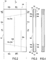
- the figure 2 shows in plan a fiber blank 101 from which a fiber preform of the blade 10 can be formed.
- the blank 101 is obtained from a strip 100 woven by three-dimensional (3D) or multilayer weaving, the strip 100 extending from generally in a direction X corresponding to the longitudinal direction of the blade to be manufactured. Weaving is carried out for example with warp threads extending in the direction X, it being noted that weaving with weft threads extending in this direction is also possible.
- a plurality of blanks 101 can be woven one after the other in the direction X. It is also possible to weave several parallel rows of blanks 101 simultaneously.
- a blank 101 comprises, in its thickness and at each of its ends 101a and 101b, a first part 102, 112, a second part 104, 114 and a third part 106, 116.
- the part 102 is located between the part 104 and the part 106 and is linked to the parts 104 and 106 by 3D weaving in an area 120 intended to form the blade of the blade and untied from the parts 104 and 106 at the level of an unbinding zone 103 comprising a first unbinding 103a between the part 102 and part 104 and a second unbinding 103b, between part 102 and part 106.
- the unbinding 103a, 103b extend over the entire width of the blank 101 (dimension in weft direction) from the end 101a from the draft 101 to unbinding funds 103c and 103d.
- the unbinding funds 103c and 103d extend between the longitudinal edges 101c and 101d of the blank 101 in a direction making a non-zero angle with respect to the weft direction in order to respect the orientation of the inner platform 14.
- Part 112 is located between part 114 and part 116 and is linked to parts 114 and 116 by 3D weaving in zone 120 intended to form the blade of the blade and untied from parts 114 and 116 at the level of a zone.
- unbinding 105 comprising a first unbinding 105a between the part 112 and the part 114 and a second unbinding 105b, between the part 112 and the part 116.
- the unbinding 105a, 105b extend over the entire width of the blank 101 from from the end 101b of the blank 101 to the unbinding bottoms 105c and 105d.
- the unbinding funds 105c and 105d extend between the longitudinal edges 101c and 101d of the blank 101 in a direction making a non-zero angle relative to the weft direction in order to respect the orientation of the external platform 16.
- an unbinding is provided between two layers of warp threads by failing to pass a weft thread through through the unbinding zone to link threads of warp layers located on either side of the unbinding.
- the plans of Figures 5 and 6 show an example of 3D weaving with interlock weave and bindings 105a and 105b, the bindings 103a and 103b being obtained in the same way as the bindings 105a and 105b.
- the unbindings are represented by dashes.
- the part 112 comprises a plurality of layers of warp threads (3 in the example illustrated) which are linked by 3D weaving.
- the parts 114 and 116 each comprise a plurality of layers of warp threads (five in the example illustrated) which are linked together by 3D weaving.
- the layers of warp threads of the parts 102, 112, 104, 114 and 106, 116 are, in the example illustrated, all linked together ( figure 5 ).
- the segments 104a, 114a and 106a, 116a of the parts 104, 106, 114, 116 which are not linked to the parts 102 and 112 are unfolded or deployed as shown on the figure 7 to form preform parts for the platforms 14, 16, the segments 104a, 114a being adjacent to the bindings 103a, 105a and the segments 106a, 116a being adjacent to the bindings 103b, 105b.
- the unfolding is carried out at the level of the unbinding funds.
- the unfolding of the segments 104a and 106a of the parts 104, 106 leads to the formation of a groove 108 between the parts 104 and 106 at their separation in the blank 101, the segment 102a of the part 102 extending from from the center of the groove 108.
- the unfolding of the segments 114a and 116a of the parts 114, 116 results in the formation of a groove 118 between the parts 114 and 116 at their separation in the blank 101, the segment 112a of the part 112 extending from the bottom of the groove 118.
- the groove 108 is filled by folding down on itself the segment 102a in said groove while the groove 118 is filled by folding down on itself the segment 112a in said groove.
- the segments 102a and 112a can be folded down in different ways. They can for example be wound on themselves in the corresponding grooves according to an increasing radius as illustrated on the figure 7 for segment 102 or be wound on themselves in the corresponding grooves in rectilinear portions substantially parallel to the edges of the groove as illustrated in the figure 8 for a segment 112a 'wound in a groove 118' present between segments 114a 'and 116a' unfolded.
- a fiber preform of the blade to be manufactured is then produced by molding using a shaping tool with deformations to obtain the desired hollow blade profile and the desired shapes for the platforms.
- a preform 210 figure 9
- a preform part 220 for the blade obtained by shaping the segment 120a ( figure 7 )
- parts 214, 216 of preforms for the interior and exterior platforms obtained by shaping the segments 104a, 106a, 114a and 116a.
- the central part of the upper surface 216a of the preform part 216 corresponding to the location of the groove 118 is filled with a preform part 218 obtained by the shaping of the segment 112a as described above.
- the central part of the lower surface of the preform part 214 corresponding to the location of the groove 108 is filled with a preform part obtained by the shaping of the segment 102a (not shown in the figure 9 ).
- a hollow blade in CMC such as that of the figure 1 can be made in the following way.
- a fibrous strip 100 is woven by three-dimensional weaving, comprising a plurality of fibrous blanks 101 oriented for example in warp direction, with unbinding zones, as shown on the figure 2 .
- Ceramic wires can be used for weaving, in particular wires based on silicon carbide (SiC), for example those supplied under the name "Nicalon” by the Japanese company Nippon Carbon.
- Other ceramic wires can be used, in particular refractory oxide wires, such as alumina Al 2 O 3 wires, in particular for CMC materials of the oxide / oxide type (fibers of the fibrous reinforcement and oxide matrix refractory).
- Carbon wires could also be used for a CMC material with carbon fiber reinforcement.
- the fibrous strip can be treated to eliminate the size present on the fibers and the presence of oxide on the surface of the fibers.
- a thin layer of coating defragilization interphase can then be formed on the fibers of the fibrous strip by chemical gas infiltration, or CVI ("Chemical Vapor Infiltration").
- the interphase material is, for example, pyrolytic carbon PyC, boron nitride BN or carbon doped with boron BC.
- the thickness of the layer formed is for example between 10 nanometers and 100 nanometers to maintain a capacity for deformation of the fibrous blanks.
- the fibrous strip is then impregnated with a consolidation composition, typically a carbon precursor resin or a ceramic precursor resin optionally diluted in a solvent. After drying, the individual fiber blanks are cut. Each blank is shaped (as illustrated by the figures 7 to 9 ) and placed in a tool for shaping the blade preform parts and the inner and outer platforms.
- a consolidation composition typically a carbon precursor resin or a ceramic precursor resin optionally diluted in a solvent.
- the resin is crosslinked and then pyrolyzed after removing the preform from the shaping tool to obtain a blade preform consolidated by the pyrolysis residue.
- the amount of consolidation resin is chosen to be sufficient but not too much so that the pyrolysis residue binds the fibers of the preform so that it can be handled while retaining its shape without the aid of tools.
- a second layer of debonding interphase coating can be formed by CVI, for example in PyC, BN or BC.
- CVI for example in PyC, BN or BC.
- the realization of an interphase coating in two layers before and after consolidation is described in the document EP 2,154,119 .
- a densification by ceramic matrix of the consolidated preform is then carried out for example by CVI.
- the matrix may be made of SiC or be a self-healing matrix comprising matrix phases of pyrolytic carbon PyC, of boron carbide B4C or of the ternary Si-BC system as described in particular in the documents US 5,246,756 and US 5,965,266 .
- Other types of ceramic matrix can be envisaged, in particular matrices of refractory oxide, for example of alumina, in particular for CMC materials of the oxide / oxide type.
- Densification is preferably carried out in two steps separated by a step of machining the blade to its desired dimensions, in particular to obtain the desired final shape for the platforms 14, 16 and possibly to obtain the desired profile of the blade 12 .
- the blade can also be made from a composite material with an organic CMO matrix (thermoplastic or thermosetting with any type of fiber preform).
- a composite material with an organic CMO matrix thermoplastic or thermosetting with any type of fiber preform.
- the densification of the fiber preform obtained in a manner known per se according to the liquid method.
- the liquid method consists in impregnating the fiber preform with a resin.
- the preform is placed in a mold which can be closed in a leaktight manner with a housing having the shape of the final molded part.
- the resin for example a thermoplastic or thermosetting resin, is injected into the entire housing to impregnate the entire fibrous part of the preform.
- the polymerization is carried out by a heat treatment (generally by heating the mold).
- the preform is still held in the mold, it has a shape corresponding to that of the part to be produced.
- the organic matrix can in particular be obtained from epoxy resins.
- the first parts 102, 112, the second parts 104, 114 and the third parts 106, 116 together comprise the same number of layers of warp threads as the rest of the fiber blank 101 located outside the unbinding zones 103 and 105, namely at the level of zone 120.
- the second and third parts 114 and 116 each comprise 5 layers of warp threads while the first part 112 comprises 3 layers of warp threads. The same applies to the first, second and third parts 102, 104 and 106 not shown on the Figures 5 and 6 .
- the first, second and third parts together comprise a number of layers of warp threads greater than the number of layers of warp threads present in the rest of the fibrous blank located outside the unbinding zones of the fibrous blank.
- one or more layers of additional warp threads are woven with the layers of warp threads of at least the second and third parts.
- the figures 10 and 11 show an end 301b of a fiber blank 301 which differs from the end 101b of the fiber blank 101 already described and illustrated in the figures 6 and 7 in that layers additional warp threads were woven with the second and third parts 314 and 316 intended to form the outer platform of the blade. More specifically, in the unbinding zone 305, a fold 315 comprising 3 layers of additional warp threads has been woven with the second part 314 from the beginning of the unbinding 305a separating the first part 312 from the second part 314 while a fold 317 comprising 3 layers of additional warp thread was woven with the third part 316 from the start of the unbinding 305b separating the first part 312 from the third part 316.
- the first part 312 is intended to be folded back on itself in order to fill the groove 318 formed between the unfolded segments of the parts 314 and 316.
- the blank 301 thus comprises, in the unbinding zone 305, first, second and third parts 312, 314 and 316 which together comprise a number of layers of warp threads greater than the number of layers of warp threads present in an area 120 s ituted outside the unbinding zones of the fibrous blank
- the first, second and third parts together comprise a number of layers of warp threads less than the number of layers of warp threads present in the rest of the fiber blank outside unbinding zones of the fibrous blank.
- one or more layers of warp threads are removed, that is to say nonwoven and extracted from the blank, at the unbinding zones of the blank.
- the figures 12 and 13 show an end 401b of a fiber blank 401 which differs from the end 101b of the fiber blank 101 already described and illustrated in the figures 6 and 7 in that layers of warp threads have been removed in an unbinding zone 405 comprising an unbinding 405a separating the first part 412 from the second part 414 and an unbinding 405b separating the first part 412 from the third part 416, the second and third parts 414 and 416 being intended to form the outer platform of the blade. More precisely, from the start of the unbinding zone 405, the two layers of warp threads C1 and C2 are no longer woven with the layers of warp threads used to form the first part 412 ( figure 13 ).
- the layers C1 and C2 can thus be removed in the unbinding zone 405 so that the first part 412 comprises only 3 layers of warp threads while the second and third parts 414 and 416 each comprise 6 layers of warp threads.
- the cumulative cumulative thicknesses e1, e2 and e3 respectively of the first, second and third parts 412, 414 and 416 is less than the thickness e4 of the part 420 of the blank intended to form the blade preform part of the dawn.
- the first part 412 is intended to be folded back on itself in order to fill the groove 418 formed between the unfolded segments of the second and third parts 414 and 416.
- the method of the invention has been described above in connection with the manufacture of a fixed outlet guide vane (OGV for " Outlet Guide Vane ”) of a turbomachine rectifier.
- OGV Outlet Guide Vane
- the method of the invention applies in particular to the manufacture of any aeronautical part comprising a body and at least one integrated platform.
- the method of the invention can in particular be used for the manufacture of movable blades of a turbomachine, stiffeners and fittings.
Landscapes
- Engineering & Computer Science (AREA)
- Chemical & Material Sciences (AREA)
- Ceramic Engineering (AREA)
- Materials Engineering (AREA)
- Mechanical Engineering (AREA)
- Manufacturing & Machinery (AREA)
- Composite Materials (AREA)
- Organic Chemistry (AREA)
- Structural Engineering (AREA)
- Textile Engineering (AREA)
- Chemical Kinetics & Catalysis (AREA)
- Inorganic Chemistry (AREA)
- General Engineering & Computer Science (AREA)
- Woven Fabrics (AREA)
- Manufacture Of Alloys Or Alloy Compounds (AREA)
- Turbine Rotor Nozzle Sealing (AREA)
- Moulding By Coating Moulds (AREA)
- Structures Of Non-Positive Displacement Pumps (AREA)
Description
L'invention se rapporte aux pièces en matériau composite comprenant un corps solidaire d'au moins une plate-forme présente à une de ses extrémités. De tels pièces concernent notamment, mais non exclusivement, les aubes de turbomachines à plates-formes intérieure et/ou extérieure intégrées pour distributeur de turbine ou redresseur de compresseur.The invention relates to parts made of composite material comprising a body integral with at least one platform present at one of its ends. Such parts relate in particular, but not exclusively, to the blades of turbomachines with integrated internal and / or external platforms for turbine distributor or compressor rectifier.
Le document
Comme illustré sur la
Une fois les parties 511 et 512 déployées, une rainure ou creux 513 apparait entre les deux parties déployées 511 et 512. Si elle n'est pas comblée, la rainure 513 peut créer une zone de faiblesse pouvant entraîner la rupture des fibres lorsque la pièce est sollicitée mécaniquement. Cette rainure peut être comblée à l'aide d'un élément de comblement rapporté qui peut comprendre de la résine seule ou une armature fibreuse (tresse, mèche, etc.) imprégnée de résine.Once the
Cependant, si cette solution de comblement permet d'améliorer la résistance mécanique de l'aube dans la zone de séparation entre les deux parties de plate-forme, elle présente toutefois encore certains inconvénients. En effet, l'ajout d'un élément de comblement rapporté complexifie la fabrication de la pièce puisqu'il rajoute des opérations supplémentaires à celles de la fabrication de pièce proprement dite (opérations secondaires pour le formage et l'insertion de l'élément de comblement sur la pièce à fabriquer). Ceci se traduit par un cout de fabrication de la pièce plus élevé. En outre, si l'ajout d'un tel élément de comblement permet d'améliorer la tenue en compression de la pièce, la tenue en traction reste cependant problématique car les rayons présentés par les parties de plate-forme à leur jonction avec la partie de pale de l'aube se déforment sous les sollicitations en traction, ce qui peut conduire à des décohésions et à un détachement de l'élément de comblement du reste de l'aube.However, if this filling solution makes it possible to improve the mechanical strength of the blade in the separation zone between the two platform parts, it nevertheless still has certain drawbacks. Indeed, the addition of an added filling element complicates the production of the part since it adds additional operations to those of the production of the part itself (secondary operations for forming and inserting the filling element on the part to be manufactured). This results in a higher manufacturing cost of the part. In addition, if the addition of such a filling element improves the compressive strength of the part, the tensile strength remains problematic, however, because the spokes presented by the platform parts at their junction with the part blades of the blade deform under the tensile stresses, which can lead to decohesions and detachment of the filling element from the rest of the blade.
L'invention a, par conséquent, pour but de fournir un procédé simplifié de fabrication d'une pièce en matériau composite à plate-forme(s) intégrée(s) qui présente une bonne tenue à la fois en compression et en traction.The invention therefore aims to provide a simplified method of manufacturing a part made of composite material with integrated platform (s) which has good resistance to both compression and traction.
A cet effet, selon l'invention, il est proposé un procédé de fabrication d'une pièce en matériau composite ayant un corps solidaire d'au moins une plate-forme présente à une extrémité dudit corps, le procédé comportant :
- la formation par tissage multicouches entre une pluralité de couches de fils de chaîne d'une ébauche fibreuse ayant une direction longitudinale correspondant à celle du corps de la pièce à réaliser, l'ébauche fibreuse étant séparée dans son épaisseur en des première, deuxième et troisième parties dans au moins une zone de déliaison voisine d'une de ses extrémités, la première partie étant située entre la deuxième partie et la troisième partie auxquelles elle est reliée par tissage en dehors de ladite au moins une zone de déliaison,
- la formation, à partir de l'ébauche fibreuse, d'une préforme de la pièce réaliser, par dépliage, de part et d'autre de la première partie, de segments de la deuxième partie et de la troisième partie non liés à la première partie, par mise en forme du segment déplié de la deuxième partie et du segment déplié de la troisième partie pour former des parties de préforme pour une plate-forme de la pièce à fabriquer, et par rabattage sur lui-même du segment de la première partie pour combler la rainure présente au niveau de la portion de séparation entre les deuxième et troisième parties,
- la densification de la préforme par une matrice pour obtenir une pièce en matériau composite ayant au moins une plate-forme intégrée.
- the formation by multilayer weaving between a plurality of layers of warp threads of a fibrous blank having a longitudinal direction corresponding to that of the body of the part to be produced, the fibrous blank being separated in its thickness into first, second and third parts in at least one unbinding zone near one of its ends, the first part being located between the second part and the third part to which it is connected by weaving outside said at least one unbinding zone,
- the formation, from the fiber blank, of a preform of the part, by unfolding, on either side of the first part, of segments of the second part and of the third part not linked to the first part, by shaping the unfolded segment of the second part and the unfolded segment of the third part to form preform parts for a platform of the workpiece, and by folding down on itself of the segment of the first part to fill the groove present at the separation portion between the second and third parts,
- densification of the preform by a matrix to obtain a piece of composite material having at least one integrated platform.
Avec le procédé de l'invention, la rainure présente entre les parties dépliées de l'ébauche fibreuse destinée à former la plate-forme est comblée avec une texture fibreuse provenant directement de l'ébauche et rattachée à celle-ci, ce qui permet d'éviter l'ajout d'un élément de comblement rapporté. Le procédé de fabrication de la pièce est ainsi simplifié tandis que la tenue en traction et compression de la pièce est améliorée, l'élément étant lié au corps de pièce par des fibres et non plus seulement par la matrice.With the method of the invention, the groove present between the unfolded parts of the fibrous blank intended to form the platform is filled with a fibrous texture coming directly from the blank and attached to it, which makes it possible to '' avoid adding an added filling element. The manufacturing process of the part is thus simplified while the tensile and compressive strength of the part is improved, the element being linked to the body of the part by fibers and no longer only by the matrix.
Par ailleurs, avec le procédé de l'invention, le nombre d'opérations nécessaires pour combler la rainure présente au niveau de la portion de séparation entre les deuxième et troisième parties est réduit par rapport à la solution de l'art antérieur consistant à rapporter un élément de comblement. Le procédé de l'invention apporte, par conséquent, un gain économique dans la fabrication de la pièce en matériau composite.Furthermore, with the method of the invention, the number of operations necessary to fill the groove present at the separation portion between the second and third parts is reduced compared to the solution of the prior art consisting in bringing back a filling element. The method of the invention therefore provides an economic gain in the manufacture of the part made of composite material.
Selon un mode particulier de réalisation, les première, deuxième et troisième parties comprennent ensemble le même nombre de couches de fils de chaîne que le reste de l'ébauche fibreuse située en dehors de ladite au moins une zone de déliaison. Ce mode de réalisation présente un avantage économique par sa simplicité de fabrication qui ne nécessite pas d'introduction de fils supplémentaires dans les différentes parties de la pièce.According to a particular embodiment, the first, second and third parts together comprise the same number of layers of warp threads as the rest of the fibrous blank situated outside said at least one unbinding zone. This embodiment has an economic advantage by its simplicity of manufacture which does not require the introduction of additional son in the different parts of the room.
Selon un autre mode particulier de réalisation, les première, deuxième et troisième parties comprennent ensemble un nombre de couches de fils de chaîne supérieur au nombre de couche de fils de chaîne présents dans le reste de l'ébauche fibreuse située en dehors de ladite au moins une zone de déliaison. Dans ce cas, une ou plusieurs couches de fils de chaîne supplémentaires peuvent être tissées avec les couches de fils de chaîne d'au moins les deuxième et troisième parties. Ce mode de réalisation permet d'épaissir certaines parties de la pièce, par exemple des plateformes, par lesquelles peuvent alors transiter des efforts importants.According to another particular embodiment, the first, second and third parts together comprise a number of layers of warp threads greater than the number of layers of warp threads present in the rest of the fibrous blank located outside said at least an unbinding zone. In this case, one or more layers of additional warp yarns can be woven with the layers of warp yarns from at least the second and third parts. This embodiment makes it possible to thicken certain parts of the part, for example platforms, through which large forces can then pass.
Selon encore un autre mode particulier de réalisation, les première, deuxième et troisième parties comprennent ensemble un nombre de couches de fils de chaîne inférieur au nombre de couches fils de chaîne présents dans le reste de l'ébauche fibreuse située en dehors de ladite au moins une zone de déliaison. Dans ce cas, une ou plusieurs couches de fils de chaîne sont retirées lors du tissage desdites au moins deuxième et troisième parties. Ce mode de réalisation permet d'amincir des parties de pièces non structurales ou dans lesquelles les efforts sont faibles afin de faciliter l'intégration de la pièce en allégeant sa masse globale.According to yet another particular embodiment, the first, second and third parts together comprise a number of layers of warp threads less than the number of layers of warp threads present in the rest of the fibrous blank located outside said at least an unbinding zone. In this case, one or more layers of warp threads are removed during the weaving of said at least second and third parts. This embodiment makes it possible to thin parts of non-structural parts or in which the forces are low in order to facilitate the integration of the part by reducing its overall mass.
D'autres caractéristiques et avantages de l'invention ressortiront de la description suivante de modes particuliers de réalisation de l'invention, donnés à titre d'exemples non limitatifs, en référence aux dessins annexés, sur lesquels :
- la
figure 1 est une vue schématique en perspective d'une aube de turbomachine ; - la
figure 2 est une vue schématique en plan d'une ébauche fibreuse tissée destinée à la réalisation d'une préforme fibreuse pour une aube du type de celle de lafigure 1 ; - la
figure 3 est une vue latérale de l'ébauche de lafigure 2 ; - la
figure 4 est une vue schématique en coupe selon le plan IV- IV de lafigure 2 ; - les
figures 5 et 6 sont des vues schématiques à échelle agrandie de plans de tissage de l'ébauche de lafigure 2 vue en coupe selon les plans V-V et VI-VI de lafigure 2 ; - les
figures 7 à 9 sont des vues schématiques montrant des étapes de la réalisation d'une préforme d'aube à partir de l'ébauche fibreuse desfigures 2 à 6 ; - la
figure 10 est une vue latérale partielle d'un autre mode de réalisation d'une ébauche fibreuse tissée destinée à la réalisation d'une préforme fibreuse pour une aube du type de celle de lafigure 1 ; - la
figure 11 est une vue schématique à échelle agrandie de plans de tissage de l'ébauche de lafigure 10 ; - la
figure 12 est une vue latérale partielle d'un autre mode de réalisation d'une ébauche fibreuse tissée destinée à la réalisation d'une préforme fibreuse pour une aube du type de celle de lafigure 1 ; - la
figure 13 est une vue schématique à échelle agrandie de plans de tissage de l'ébauche de lafigure 12 ; - la
figure 14 est une vue schématique en perspective d'une ébauche fibreuse destinée à la réalisation d'une préforme fibreuse pour une aube selon l'art antérieur ; - la
figure 15 est une vue latérale de l'ébauche fibreuse de lafigure 14 après déploiement des parties de l'ébauche destinées à former des plates-formes intérieur et extérieur.
- the
figure 1 is a schematic perspective view of a turbomachine blade; - the
figure 2 is a schematic plan view of a woven fibrous blank intended for producing a fibrous preform for a blade of the type of that of thefigure 1 ; - the
figure 3 is a side view of the draft of thefigure 2 ; - the
figure 4 is a schematic sectional view along plane IV- IV of thefigure 2 ; - the
Figures 5 and 6 are schematic views on an enlarged scale of weaving plans of the blank of thefigure 2 sectional view according to plans VV and VI-VI of thefigure 2 ; - the
figures 7 to 9 are schematic views showing steps of producing a blade preform from the fibrous blank of thefigures 2 to 6 ; - the
figure 10 is a partial side view of another embodiment of a woven fibrous blank intended for producing a fibrous preform for a blade of the type of that of thefigure 1 ; - the
figure 11 is a schematic view on an enlarged scale of weaving planes of the blank of thefigure 10 ; - the
figure 12 is a partial side view of another embodiment of a woven fibrous blank intended for producing a fibrous preform for a blade of the type of that of thefigure 1 ; - the
figure 13 is a schematic view on an enlarged scale of weaving planes of the blank of thefigure 12 ; - the
figure 14 is a schematic perspective view of a fibrous blank intended for the production of a fibrous preform for a blade according to the prior art; - the
figure 15 is a side view of the fibrous blank of thefigure 14 after deployment of the parts of the blank intended to form interior and exterior platforms.
La
Dans tout le texte, les termes "intérieur" et "extérieur" sont utilisés en référence à la position radiale par rapport à l'axe de la turbomachine.Throughout the text, the terms "interior" and "exterior" are used with reference to the radial position relative to the axis of the turbomachine.
La face extérieure 14b de la plate-forme 14 et la face intérieure 16a de la plate-forme 16 sont destinées à délimiter la veine d'écoulement de gaz dans la turbine après montage de l'aube 10 dans un carter de turbine.The
La pale 12 s'étend entre les plates-formes 14 et 16, dont elle est solidaire. Dans l'exemple illustré, les plates-formes 14, 16 s'étendent entre leurs extrémités amont et aval suivant des directions générales qui forment des angles non nuls par rapport à un plan normal à la direction longitudinale de la pale 12.The blade 12 extends between the
L'aube 10 est en matériau composite. Sa fabrication comprend la formation d'une préforme fibreuse ayant une forme correspondant à celle de l'aube et la densification de la préforme par une matrice.The
La
L'ébauche 101 est obtenue à partir d'une bande 100 tissée par tissage tridimensionnel (3D) ou multicouches, la bande 100 s'étendant de façon générale dans une direction X correspondant à la direction longitudinale de l'aube à fabriquer. Le tissage est réalisé par exemple avec des fils de chaîne s'étendant dans la direction X, étant noté qu'un tissage avec des fils de trame s'étendant dans cette direction est également possible. Une pluralité d'ébauches 101 peuvent être tissées l'une à la suite de l'autre dans la direction X. On peut aussi tisser simultanément plusieurs rangées parallèles d'ébauches 101.The blank 101 is obtained from a
Dans le mode de réalisation des
La partie 112 est située entre la partie 114 et la partie 116 et est liée aux parties 114 et 116 par tissage 3D dans la zone 120 destinée à former la pale de l'aube et déliée des parties 114 et 116 au niveau d'une zone de déliaison 105 comprenant une première déliaison 105a entre la partie 112 et la partie 114 et une deuxième déliaisons 105b, entre la partie 112 et la partie 116. Les déliaisons 105a, 105b s'étendent sur toute la largeur de l'ébauche 101 à partir de l'extrémité 101b de l'ébauche 101 jusqu'à des fonds de déliaison 105c et 105d. Les fonds de déliaison 105c et 105d s'étendent entre les bords longitudinaux 101c et 101d de l'ébauche 101 suivant une direction faisant un angle non nul par rapport à la direction trame afin de respecter l'orientation de la plate-forme extérieure 16.
De façon bien connue, une déliaison est ménagée entre deux couches de fils de chaîne en omettant de faire passer un fil de trame à travers la zone de déliaison pour lier des fils de couches de chaîne situées de part et d'autre de la déliaison.As is well known, an unbinding is provided between two layers of warp threads by failing to pass a weft thread through through the unbinding zone to link threads of warp layers located on either side of the unbinding.
Les plans des
Après tissage, les segments 104a, 114a et 106a, 116a des parties 104, 106, 114, 116 non liées aux parties 102 et 112 sont dépliés ou déployés comme montré sur la
Comme illustré sur la
Conformément à l'invention, la rainure 108 est comblée par rabattage sur lui même du segment 102a dans ladite rainure tandis que la rainure 118 est comblée par rabattage sur lui-même du segment 112a dans ladite rainure. Les segments 102a et 112a peuvent être rabattus de différentes façons. Ils peuvent par exemple être enroulés sur eux-mêmes dans les rainures correspondantes suivant un rayon croissant comme illustrée sur la
Une préforme fibreuse de l'aube à fabriquer est ensuite réalisée par moulage au moyen d'un outillage de conformation avec déformations pour obtenir le profil de pale creuse désiré et les formes désirées pour les plates-formes. On obtient une préforme 210 (
Une aube creuse en CMC telle que celle de la
Une bande fibreuse 100 est tissée par tissage tridimensionnel, comprenant une pluralité d'ébauches fibreuses 101 orientées par exemple en sens chaîne, avec zones de déliaison, comme montré sur la
De façon connue, la bande fibreuse peut être traitée pour éliminer l'ensimage présent sur les fibres et la présence d'oxyde à la surface des fibres.In known manner, the fibrous strip can be treated to eliminate the size present on the fibers and the presence of oxide on the surface of the fibers.
Egalement de façon connue, une mince couche de revêtement d'interphase de défragilisation peut être ensuite formée sur les fibres de la bande fibreuse par infiltration chimique en phase gazeuse, ou CVI ("Chemical Vapour Infiltration"). Le matériau d'interphase est par exemple du carbone pyrolytique PyC, du nitrure de bore BN ou du carbone dopé au bore BC. L'épaisseur de la couche formée est par exemple comprise entre 10 nanomètres et 100 nanomètres pour conserver une capacité de déformation des ébauches fibreuses.Also in a known manner, a thin layer of coating defragilization interphase can then be formed on the fibers of the fibrous strip by chemical gas infiltration, or CVI ("Chemical Vapor Infiltration"). The interphase material is, for example, pyrolytic carbon PyC, boron nitride BN or carbon doped with boron BC. The thickness of the layer formed is for example between 10 nanometers and 100 nanometers to maintain a capacity for deformation of the fibrous blanks.
La bande fibreuse est ensuite imprégnée par une composition de consolidation, typiquement une résine précurseur de carbone ou une résine précurseur de céramique éventuellement diluée dans un solvant. Après séchage, les ébauches fibreuses individuelles sont découpées. Chaque ébauche est mise en forme (comme illustré par les
Ensuite, la résine est réticulée puis pyrolysée après avoir retiré la préforme de l'outillage de conformation pour obtenir une préforme d'aube consolidée par le résidu de pyrolyse. La quantité de résine de consolidation est choisie suffisante mais sans trop d'excès pour que le résidu de pyrolyse lie les fibres de la préforme afin que celle-ci soit manipulable en conservant sa forme sans l'assistance d'un outillage.Then, the resin is crosslinked and then pyrolyzed after removing the preform from the shaping tool to obtain a blade preform consolidated by the pyrolysis residue. The amount of consolidation resin is chosen to be sufficient but not too much so that the pyrolysis residue binds the fibers of the preform so that it can be handled while retaining its shape without the aid of tools.
Une deuxième couche de revêtement d'interphase de défragilisation peut être formée par CVI, par exemple en PyC, BN ou BC. La réalisation d'un revêtement d'interphase en deux couches avant et après consolidation est décrite dans le document
Une densification par matrice céramique de la préforme consolidée est ensuite réalisée par exemple par CVI. La matrice peut être en SiC ou être une matrice autocicatrisante comprenant des phases de matrice en carbone pyrolytique PyC, en carbure de bore B4C ou en système ternaire Si-B-C comme décrit notamment dans les documents
La densification est de préférence réalisée en deux étapes séparées par une étape d'usinage de l'aube à ses dimensions désirées notamment pour obtenir la forme finale désirée pour les plates-formes 14, 16 et éventuellement pour obtenir le profil désiré de la pale 12.Densification is preferably carried out in two steps separated by a step of machining the blade to its desired dimensions, in particular to obtain the desired final shape for the
L'aube peut être également fabriquée en matériau composite à matrice organique CMO (thermoplastique ou thermodurcissable avec préforme fibreuse de tout type). Dans ce cas, la densification de la préforme fibreuse obtenue de façon connue en soi suivant le procédé par voie liquide.The blade can also be made from a composite material with an organic CMO matrix (thermoplastic or thermosetting with any type of fiber preform). In this case, the densification of the fiber preform obtained in a manner known per se according to the liquid method.
Le procédé par voie liquide consiste à imprégner la préforme fibreuse par une résine. La préforme est placée dans un moule pouvant être fermé de manière étanche avec un logement ayant la forme de la pièce finale moulée. Ensuite, on injecte la résine, par exemple une résine thermoplastique ou thermodurcissable, dans tout le logement pour imprégner toute la partie fibreuse de la préforme.The liquid method consists in impregnating the fiber preform with a resin. The preform is placed in a mold which can be closed in a leaktight manner with a housing having the shape of the final molded part. Then, the resin, for example a thermoplastic or thermosetting resin, is injected into the entire housing to impregnate the entire fibrous part of the preform.
La polymérisation est réalisée par un traitement thermique (généralement par chauffage du moule). La préforme étant toujours maintenue dans le moule, elle a une forme correspondant à celle de la pièce à réaliser. La matrice organique peut être notamment obtenue à partir de résines époxydes.The polymerization is carried out by a heat treatment (generally by heating the mold). The preform is still held in the mold, it has a shape corresponding to that of the part to be produced. The organic matrix can in particular be obtained from epoxy resins.
Dans le mode de réalisation décrit ci-avant, les premières parties 102, 112, les deuxièmes parties 104, 114 et les troisième parties 106, 116 comprennent ensemble le même nombre de couches de fils de chaîne que le reste de l'ébauche fibreuse 101 située en dehors des zones de déliaison 103 et 105, à savoir au niveau de la zone 120. Dans l'exemple illustré sur les
Selon un autre mode de réalisation de l'invention, les première, deuxième et troisième parties comprennent ensemble un nombre de couches de fils de chaîne supérieur au nombre de couche de fils de chaîne présents dans le reste de l'ébauche fibreuse située en dehors des zones de déliaison de l'ébauche fibreuse. Dans ce cas, une ou plusieurs couches de fils de chaîne supplémentaires sont tissées avec les couches de fils de chaîne d'au moins les deuxième et troisième parties.According to another embodiment of the invention, the first, second and third parts together comprise a number of layers of warp threads greater than the number of layers of warp threads present in the rest of the fibrous blank located outside the unbinding zones of the fibrous blank. In this case, one or more layers of additional warp threads are woven with the layers of warp threads of at least the second and third parts.
Les
Selon encore un autre mode de réalisation de l'invention, les première, deuxième et troisième parties comprennent ensemble un nombre de couches de fils de chaîne inférieur au nombre de couche de fils de chaîne présents dans le reste de l'ébauche fibreuse située en dehors des zones de déliaison de l'ébauche fibreuse. Dans ce cas, une ou plusieurs couches de fils de chaîne sont retirées, c'est-à-dire non tissées et extraites de l'ébauche, au niveau des zones de déliaison de l'ébauche.According to yet another embodiment of the invention, the first, second and third parts together comprise a number of layers of warp threads less than the number of layers of warp threads present in the rest of the fiber blank outside unbinding zones of the fibrous blank. In this case, one or more layers of warp threads are removed, that is to say nonwoven and extracted from the blank, at the unbinding zones of the blank.
Les
Le procédé de l'invention a été décrit ci-avant en relation avec la fabrication d'une aube fixe directrice de sortie (OGV pour « Outlet Guide Vane ») d'un redresseur de turbomachine. Toutefois, le procédé de l'invention s'applique notamment à la fabrication de toute pièce aéronautique comprenant un corps et au moins une plateforme intégrée. Le procédé de l'invention peut notamment être utilisé pour la fabrication d'aubes mobiles de turbomachine, de raidisseurs et de ferrures.The method of the invention has been described above in connection with the manufacture of a fixed outlet guide vane (OGV for " Outlet Guide Vane ") of a turbomachine rectifier. However, the method of the invention applies in particular to the manufacture of any aeronautical part comprising a body and at least one integrated platform. The method of the invention can in particular be used for the manufacture of movable blades of a turbomachine, stiffeners and fittings.
Claims (7)
- A method of fabricating a composite material part (10) having a body (12) secured to at least one platform (14; 16) present at one end of said body, the method comprising:- using multilayer weaving between a plurality of layers of warp yarns to form a fiber blank (101) having a longitudinal direction corresponding to the longitudinal direction of the body (12) of the part (10) that is to be made, the fiber blank being separated in its thickness direction into first, second, and third portions (102, 104, 106; 112, 114, 116) in at least one zone of non-interlinking (103; 105) adjacent to one of its ends, the first portion (102; 112) being situated between the second and third portions (104, 106; 114, 116), to which it is connected by weaving outside said at least one zone of non-interlinking (103; 105);- using the fiber blank (101) to form a preform for the part that is to be made by folding out segments (104a, 106a; 114a, 116a) of the second and third portions that are not interlinked with the first portion on opposite sides of the first portion, by shaping the folded-out segments (104a, 106a; 114a, 116a) of the second and third portions to form preform portions for a platform (14; 16) of the part (10) to be fabricated, and by folding down the segment (102; 112a) of the first portion in order to fill in the groove (108; 118) present in the gap between the second and third portions (104, 106; 114, 116); and- densifying the preform with a matrix in order to obtain a part (10) made of composite material having at least one integrated platform (14; 16).
- A method according to claim 1, characterized in that the first, second, and third portions (102, 104, 106; 112, 114, 116) together have the same number of layers of warp yarns as the remainder (120) of the fiber blank (101) situated outside said at least one zone of non-interlinking (103; 105).
- A method according to claim 1, characterized in that the first, second, and third portions (312, 314, 316) together comprise a number of warp yarn layers that is greater than the number of warp yarn layers present in the remainder (320) of the fiber blank (301) situated outside said at least one zone of non-interlinking (305).
- A method according to claim 3, characterized in that one or more additional layers of warp layers are woven together with the layers of warp yarns of at least the second and third portions (314, 316).
- A method according to claim 1, characterized in that the first, second, and third portions (412, 414, 416) together comprise a number of warp yarn layers that is less than the number of warp yarn layers present in the remainder (420) of the fiber blank (401) situated outside said at least one zone of non-interlinking (405).
- A method according to claim 5, characterized in that one or more layers of warp layers are withdrawn during the weaving at least of said second and third portions (414, 416).
- A method according to any one of claims 1 to 6, characterized in that the composite material part corresponds to an aviation part selected from at least one of the following parts: a turbine engine vane, a turbine engine blade, a stiffener, and a fitting.
Applications Claiming Priority (2)
| Application Number | Priority Date | Filing Date | Title |
|---|---|---|---|
| FR1560649A FR3043355B1 (en) | 2015-11-06 | 2015-11-06 | METHOD FOR MANUFACTURING A COMPOSITE MATERIAL PART COMPRISING A SOLIDARY BODY OF ONE OR MORE PLATFORMS |
| PCT/FR2016/052848 WO2017077240A1 (en) | 2015-11-06 | 2016-11-03 | Method for manufacturing a component made of composite material comprising a body integral with one or more platforms |
Publications (2)
| Publication Number | Publication Date |
|---|---|
| EP3370951A1 EP3370951A1 (en) | 2018-09-12 |
| EP3370951B1 true EP3370951B1 (en) | 2020-01-01 |
Family
ID=55236597
Family Applications (1)
| Application Number | Title | Priority Date | Filing Date |
|---|---|---|---|
| EP16809128.8A Active EP3370951B1 (en) | 2015-11-06 | 2016-11-03 | Method for manufacturing a component made of composite material comprising a body integral with one or more platforms |
Country Status (9)
| Country | Link |
|---|---|
| US (1) | US10532521B2 (en) |
| EP (1) | EP3370951B1 (en) |
| JP (1) | JP6862440B2 (en) |
| CN (1) | CN108367524B (en) |
| BR (1) | BR112018009047B1 (en) |
| CA (1) | CA3004161C (en) |
| FR (1) | FR3043355B1 (en) |
| RU (1) | RU2717808C2 (en) |
| WO (1) | WO2017077240A1 (en) |
Families Citing this family (7)
| Publication number | Priority date | Publication date | Assignee | Title |
|---|---|---|---|---|
| FR3037097B1 (en) * | 2015-06-03 | 2017-06-23 | Snecma | COMPOSITE AUBE COMPRISING A PLATFORM WITH A STIFFENER |
| US11035239B2 (en) * | 2018-10-25 | 2021-06-15 | General Electric Company | Ceramic matrix composite turbine nozzle shell and method of assembly |
| US11572162B2 (en) * | 2019-05-29 | 2023-02-07 | Lockheed Martin Corporation | Securing assembly for a rotor blade |
| FR3116753B1 (en) * | 2020-12-01 | 2023-05-26 | Safran Aircraft Engines | Process for manufacturing a blade made of composite material with platforms and integrated fixing lugs |
| FR3120910A1 (en) * | 2021-03-17 | 2022-09-23 | Safran Aircraft Engines | Composite turbomachine part formed of a core surrounded by two 3D woven fiber preforms |
| FR3130192B1 (en) | 2021-12-09 | 2023-11-03 | Safran | METHOD FOR MANUFACTURING A BLADE PART FOR AN AIRCRAFT TURBOMACHINE |
| FR3141876A1 (en) * | 2022-11-15 | 2024-05-17 | Safran | Method for manufacturing a grid preform, method for manufacturing a composite material grid, grid preform and composite material grid |
Family Cites Families (19)
| Publication number | Priority date | Publication date | Assignee | Title |
|---|---|---|---|---|
| JPS58117160A (en) * | 1981-12-28 | 1983-07-12 | 東レ株式会社 | Beam material |
| US5246756A (en) | 1992-01-29 | 1993-09-21 | Mobil Oil Corporation | Release sheet |
| FR2732338B1 (en) | 1995-03-28 | 1997-06-13 | Europ Propulsion | COMPOSITE MATERIAL PROTECTED AGAINST OXIDATION BY SELF-HEALING MATRIX AND MANUFACTURING METHOD THEREOF |
| JP3591347B2 (en) * | 1998-12-15 | 2004-11-17 | 株式会社豊田自動織機 | Fiber structure for filling voids |
| US20080060755A1 (en) * | 2006-09-13 | 2008-03-13 | General Electric Corporation | composite corner and method for making composite corner |
| US8540833B2 (en) * | 2008-05-16 | 2013-09-24 | The Boeing Company | Reinforced stiffeners and method for making the same |
| FR2933970B1 (en) * | 2008-07-21 | 2012-05-11 | Snecma Propulsion Solide | METHOD FOR MANUFACTURING A PIECE OF THERMOSTRUCTURAL COMPOSITE MATERIAL AND PIECE THUS OBTAINED |
| FR2939130B1 (en) * | 2008-11-28 | 2011-09-16 | Snecma Propulsion Solide | PROCESS FOR MANUFACTURING COMPOUND FORM SHAPE PIECE OF COMPOSITE MATERIAL |
| FR2943942B1 (en) * | 2009-04-06 | 2016-01-29 | Snecma | PROCESS FOR MANUFACTURING A TURBOMACHINE BLADE OF COMPOSITE MATERIAL |
| CN102666050B (en) * | 2009-10-01 | 2015-09-16 | 奥尔巴尼工程两合公司 | Woven preform, composite and manufacture method thereof |
| FR2961845B1 (en) * | 2010-06-28 | 2013-06-28 | Snecma Propulsion Solide | TURBOMACHINE DAWN WITH COMPLEMENTARY PAIRE / IMPAIRE GEOMETRY AND METHOD OF MANUFACTURING THE SAME |
| WO2012007780A1 (en) * | 2010-07-13 | 2012-01-19 | Learjet Inc. | Composite structure and method of forming same |
| EP2570254A1 (en) * | 2011-09-15 | 2013-03-20 | Siemens Aktiengesellschaft | Method for manufacturing a wind turbine rotor blade with a shear web |
| FR2983428B1 (en) * | 2011-12-01 | 2014-01-17 | Snecma Propulsion Solide | PROCESS FOR MANUFACTURING A TURBOMACHINE BLADE IN COMPOSITE MATERIAL WITH INTEGRATED PLATFORMS |
| US9308708B2 (en) * | 2012-03-23 | 2016-04-12 | General Electric Company | Process for producing ceramic composite components |
| CN103264513B (en) * | 2013-05-30 | 2015-10-21 | 中国商用飞机有限责任公司 | The overall co-curing moulding technique of composite many beams box section |
| US9827710B2 (en) * | 2014-02-04 | 2017-11-28 | The Boeing Company | Radius filler and method of manufacturing same |
| CN203792728U (en) * | 2014-03-03 | 2014-08-27 | 沈阳飞机工业(集团)有限公司 | Performing tooling of prepreg filled with 0-degree carbon fibers |
| CN104260371B (en) * | 2014-09-15 | 2016-08-24 | 沈阳飞机工业(集团)有限公司 | Composite R angle strengthens with zero degree fibre bundle forming frock and forming method |
-
2015
- 2015-11-06 FR FR1560649A patent/FR3043355B1/en not_active Expired - Fee Related
-
2016
- 2016-11-03 CA CA3004161A patent/CA3004161C/en active Active
- 2016-11-03 WO PCT/FR2016/052848 patent/WO2017077240A1/en active Application Filing
- 2016-11-03 RU RU2018120734A patent/RU2717808C2/en active
- 2016-11-03 BR BR112018009047-6A patent/BR112018009047B1/en active IP Right Grant
- 2016-11-03 US US15/773,897 patent/US10532521B2/en active Active
- 2016-11-03 JP JP2018522960A patent/JP6862440B2/en active Active
- 2016-11-03 EP EP16809128.8A patent/EP3370951B1/en active Active
- 2016-11-03 CN CN201680072046.1A patent/CN108367524B/en active Active
Non-Patent Citations (1)
| Title |
|---|
| None * |
Also Published As
| Publication number | Publication date |
|---|---|
| CN108367524B (en) | 2020-08-14 |
| BR112018009047A2 (en) | 2018-10-30 |
| RU2018120734A3 (en) | 2020-02-03 |
| JP2019500533A (en) | 2019-01-10 |
| FR3043355B1 (en) | 2017-12-22 |
| RU2018120734A (en) | 2019-12-06 |
| CA3004161A1 (en) | 2017-05-11 |
| WO2017077240A1 (en) | 2017-05-11 |
| EP3370951A1 (en) | 2018-09-12 |
| BR112018009047A8 (en) | 2019-02-26 |
| US20180319101A1 (en) | 2018-11-08 |
| US10532521B2 (en) | 2020-01-14 |
| CA3004161C (en) | 2023-03-21 |
| CN108367524A (en) | 2018-08-03 |
| RU2717808C2 (en) | 2020-03-25 |
| JP6862440B2 (en) | 2021-04-21 |
| BR112018009047B1 (en) | 2022-02-22 |
| FR3043355A1 (en) | 2017-05-12 |
Similar Documents
| Publication | Publication Date | Title |
|---|---|---|
| EP3370951B1 (en) | Method for manufacturing a component made of composite material comprising a body integral with one or more platforms | |
| EP3019398B1 (en) | Composite rotor blade for aircraft | |
| EP2802702B1 (en) | Pi-section reinforcing piece made of composite material, notably turbomachine fan platform, and method of manufacturing same | |
| EP2516263B1 (en) | Aircraft propeller blade | |
| EP2652185B1 (en) | Fibrous structure for a part made of composite material having one or more arch-shaped portions | |
| EP2785980B1 (en) | Hollow-blade turbine vane made from composite material, turbine or compressor including a nozzle or guide vane assembly formed by such blades, and turbomachine comprising same | |
| WO2013079860A1 (en) | Method for producing a turbomachine vane made from composite material and including integrated platforms | |
| FR3076814A1 (en) | DARK OR PROPELLER BLADE COMPOSITE WITH INTEGRATED LONGERON FOR AIRCRAFT | |
| EP2681036B1 (en) | Component made of composite material comprising boss elements and corresponding production method | |
| EP3827119B1 (en) | Fiber texture for a casing made of composite material with improved impact resistance | |
| EP4051476B1 (en) | Woven fibrous preform for producing a composite part, especially a turbomachine blade | |
| EP3482050B1 (en) | Platform with extension piece for a turbomachine fan and method for producing the same | |
| EP3676431B1 (en) | Woven fibrous structure for forming a casing preform | |
| FR2961846A1 (en) | TURBOMACHINE TURBOMACHINE WITH COMPLEMENTARY ASYMMETRIC GEOMETRY | |
| WO2012098323A1 (en) | Fibrous structure for a part made of a composite material and having a complex shape | |
| EP3911841B1 (en) | Aircraft composite blade with particular weaving of a fiber preform receiving a pocket filled with a structural foam | |
| EP3827118B1 (en) | Fiber texture for a casing made of composite material with improved shear resistance | |
| FR2970898A1 (en) | Composite part i.e. composite casing, for turboprop engine of aircraft, has embossing element whose fibrous reinforcement is traversed by multiple pins that are extended from reinforcement of ring shaped structural body | |
| EP4255721A1 (en) | Method for manufacturing a vane made of a composite material with integrated attachment lugs and platforms | |
| FR3066715A1 (en) | FIBROUS TEXTURE FOR MANUFACTURING AN AERONAUTICAL MOTOR CASING |
Legal Events
| Date | Code | Title | Description |
|---|---|---|---|
| STAA | Information on the status of an ep patent application or granted ep patent |
Free format text: STATUS: UNKNOWN |
|
| STAA | Information on the status of an ep patent application or granted ep patent |
Free format text: STATUS: THE INTERNATIONAL PUBLICATION HAS BEEN MADE |
|
| PUAI | Public reference made under article 153(3) epc to a published international application that has entered the european phase |
Free format text: ORIGINAL CODE: 0009012 |
|
| STAA | Information on the status of an ep patent application or granted ep patent |
Free format text: STATUS: REQUEST FOR EXAMINATION WAS MADE |
|
| 17P | Request for examination filed |
Effective date: 20180507 |
|
| AK | Designated contracting states |
Kind code of ref document: A1 Designated state(s): AL AT BE BG CH CY CZ DE DK EE ES FI FR GB GR HR HU IE IS IT LI LT LU LV MC MK MT NL NO PL PT RO RS SE SI SK SM TR |
|
| AX | Request for extension of the european patent |
Extension state: BA ME |
|
| DAV | Request for validation of the european patent (deleted) | ||
| DAX | Request for extension of the european patent (deleted) | ||
| GRAP | Despatch of communication of intention to grant a patent |
Free format text: ORIGINAL CODE: EPIDOSNIGR1 |
|
| STAA | Information on the status of an ep patent application or granted ep patent |
Free format text: STATUS: GRANT OF PATENT IS INTENDED |
|
| RIC1 | Information provided on ipc code assigned before grant |
Ipc: C04B 35/563 20060101ALN20190516BHEP Ipc: B29C 70/48 20060101ALI20190516BHEP Ipc: C04B 35/80 20060101ALN20190516BHEP Ipc: C04B 35/628 20060101ALN20190516BHEP Ipc: B29C 70/22 20060101ALI20190516BHEP Ipc: B29L 31/08 20060101ALI20190516BHEP Ipc: B29L 31/00 20060101ALI20190516BHEP Ipc: C04B 35/571 20060101ALN20190516BHEP Ipc: C04B 35/83 20060101ALN20190516BHEP Ipc: F01D 5/28 20060101ALI20190516BHEP Ipc: B29D 99/00 20100101AFI20190516BHEP |
|
| INTG | Intention to grant announced |
Effective date: 20190613 |
|
| GRAS | Grant fee paid |
Free format text: ORIGINAL CODE: EPIDOSNIGR3 |
|
| GRAA | (expected) grant |
Free format text: ORIGINAL CODE: 0009210 |
|
| STAA | Information on the status of an ep patent application or granted ep patent |
Free format text: STATUS: THE PATENT HAS BEEN GRANTED |
|
| AK | Designated contracting states |
Kind code of ref document: B1 Designated state(s): AL AT BE BG CH CY CZ DE DK EE ES FI FR GB GR HR HU IE IS IT LI LT LU LV MC MK MT NL NO PL PT RO RS SE SI SK SM TR |
|
| REG | Reference to a national code |
Ref country code: GB Ref legal event code: FG4D Free format text: NOT ENGLISH |
|
| REG | Reference to a national code |
Ref country code: CH Ref legal event code: EP Ref country code: AT Ref legal event code: REF Ref document number: 1219256 Country of ref document: AT Kind code of ref document: T Effective date: 20200115 |
|
| REG | Reference to a national code |
Ref country code: IE Ref legal event code: FG4D Free format text: LANGUAGE OF EP DOCUMENT: FRENCH |
|
| REG | Reference to a national code |
Ref country code: DE Ref legal event code: R096 Ref document number: 602016027493 Country of ref document: DE |
|
| REG | Reference to a national code |
Ref country code: SE Ref legal event code: TRGR |
|
| REG | Reference to a national code |
Ref country code: NL Ref legal event code: MP Effective date: 20200101 |
|
| REG | Reference to a national code |
Ref country code: LT Ref legal event code: MG4D |
|
| PG25 | Lapsed in a contracting state [announced via postgrant information from national office to epo] |
Ref country code: CZ Free format text: LAPSE BECAUSE OF FAILURE TO SUBMIT A TRANSLATION OF THE DESCRIPTION OR TO PAY THE FEE WITHIN THE PRESCRIBED TIME-LIMIT Effective date: 20200101 Ref country code: PT Free format text: LAPSE BECAUSE OF FAILURE TO SUBMIT A TRANSLATION OF THE DESCRIPTION OR TO PAY THE FEE WITHIN THE PRESCRIBED TIME-LIMIT Effective date: 20200527 Ref country code: LT Free format text: LAPSE BECAUSE OF FAILURE TO SUBMIT A TRANSLATION OF THE DESCRIPTION OR TO PAY THE FEE WITHIN THE PRESCRIBED TIME-LIMIT Effective date: 20200101 Ref country code: RS Free format text: LAPSE BECAUSE OF FAILURE TO SUBMIT A TRANSLATION OF THE DESCRIPTION OR TO PAY THE FEE WITHIN THE PRESCRIBED TIME-LIMIT Effective date: 20200101 Ref country code: NO Free format text: LAPSE BECAUSE OF FAILURE TO SUBMIT A TRANSLATION OF THE DESCRIPTION OR TO PAY THE FEE WITHIN THE PRESCRIBED TIME-LIMIT Effective date: 20200401 Ref country code: FI Free format text: LAPSE BECAUSE OF FAILURE TO SUBMIT A TRANSLATION OF THE DESCRIPTION OR TO PAY THE FEE WITHIN THE PRESCRIBED TIME-LIMIT Effective date: 20200101 Ref country code: NL Free format text: LAPSE BECAUSE OF FAILURE TO SUBMIT A TRANSLATION OF THE DESCRIPTION OR TO PAY THE FEE WITHIN THE PRESCRIBED TIME-LIMIT Effective date: 20200101 |
|
| PG25 | Lapsed in a contracting state [announced via postgrant information from national office to epo] |
Ref country code: IS Free format text: LAPSE BECAUSE OF FAILURE TO SUBMIT A TRANSLATION OF THE DESCRIPTION OR TO PAY THE FEE WITHIN THE PRESCRIBED TIME-LIMIT Effective date: 20200501 Ref country code: GR Free format text: LAPSE BECAUSE OF FAILURE TO SUBMIT A TRANSLATION OF THE DESCRIPTION OR TO PAY THE FEE WITHIN THE PRESCRIBED TIME-LIMIT Effective date: 20200402 Ref country code: HR Free format text: LAPSE BECAUSE OF FAILURE TO SUBMIT A TRANSLATION OF THE DESCRIPTION OR TO PAY THE FEE WITHIN THE PRESCRIBED TIME-LIMIT Effective date: 20200101 Ref country code: LV Free format text: LAPSE BECAUSE OF FAILURE TO SUBMIT A TRANSLATION OF THE DESCRIPTION OR TO PAY THE FEE WITHIN THE PRESCRIBED TIME-LIMIT Effective date: 20200101 Ref country code: BG Free format text: LAPSE BECAUSE OF FAILURE TO SUBMIT A TRANSLATION OF THE DESCRIPTION OR TO PAY THE FEE WITHIN THE PRESCRIBED TIME-LIMIT Effective date: 20200401 |
|
| REG | Reference to a national code |
Ref country code: DE Ref legal event code: R097 Ref document number: 602016027493 Country of ref document: DE |
|
| PG25 | Lapsed in a contracting state [announced via postgrant information from national office to epo] |
Ref country code: DK Free format text: LAPSE BECAUSE OF FAILURE TO SUBMIT A TRANSLATION OF THE DESCRIPTION OR TO PAY THE FEE WITHIN THE PRESCRIBED TIME-LIMIT Effective date: 20200101 Ref country code: EE Free format text: LAPSE BECAUSE OF FAILURE TO SUBMIT A TRANSLATION OF THE DESCRIPTION OR TO PAY THE FEE WITHIN THE PRESCRIBED TIME-LIMIT Effective date: 20200101 Ref country code: SM Free format text: LAPSE BECAUSE OF FAILURE TO SUBMIT A TRANSLATION OF THE DESCRIPTION OR TO PAY THE FEE WITHIN THE PRESCRIBED TIME-LIMIT Effective date: 20200101 Ref country code: ES Free format text: LAPSE BECAUSE OF FAILURE TO SUBMIT A TRANSLATION OF THE DESCRIPTION OR TO PAY THE FEE WITHIN THE PRESCRIBED TIME-LIMIT Effective date: 20200101 Ref country code: RO Free format text: LAPSE BECAUSE OF FAILURE TO SUBMIT A TRANSLATION OF THE DESCRIPTION OR TO PAY THE FEE WITHIN THE PRESCRIBED TIME-LIMIT Effective date: 20200101 Ref country code: SK Free format text: LAPSE BECAUSE OF FAILURE TO SUBMIT A TRANSLATION OF THE DESCRIPTION OR TO PAY THE FEE WITHIN THE PRESCRIBED TIME-LIMIT Effective date: 20200101 |
|
| PLBE | No opposition filed within time limit |
Free format text: ORIGINAL CODE: 0009261 |
|
| STAA | Information on the status of an ep patent application or granted ep patent |
Free format text: STATUS: NO OPPOSITION FILED WITHIN TIME LIMIT |
|
| REG | Reference to a national code |
Ref country code: AT Ref legal event code: MK05 Ref document number: 1219256 Country of ref document: AT Kind code of ref document: T Effective date: 20200101 |
|
| 26N | No opposition filed |
Effective date: 20201002 |
|
| PG25 | Lapsed in a contracting state [announced via postgrant information from national office to epo] |
Ref country code: AT Free format text: LAPSE BECAUSE OF FAILURE TO SUBMIT A TRANSLATION OF THE DESCRIPTION OR TO PAY THE FEE WITHIN THE PRESCRIBED TIME-LIMIT Effective date: 20200101 |
|
| PG25 | Lapsed in a contracting state [announced via postgrant information from national office to epo] |
Ref country code: SI Free format text: LAPSE BECAUSE OF FAILURE TO SUBMIT A TRANSLATION OF THE DESCRIPTION OR TO PAY THE FEE WITHIN THE PRESCRIBED TIME-LIMIT Effective date: 20200101 Ref country code: PL Free format text: LAPSE BECAUSE OF FAILURE TO SUBMIT A TRANSLATION OF THE DESCRIPTION OR TO PAY THE FEE WITHIN THE PRESCRIBED TIME-LIMIT Effective date: 20200101 |
|
| PG25 | Lapsed in a contracting state [announced via postgrant information from national office to epo] |
Ref country code: MC Free format text: LAPSE BECAUSE OF FAILURE TO SUBMIT A TRANSLATION OF THE DESCRIPTION OR TO PAY THE FEE WITHIN THE PRESCRIBED TIME-LIMIT Effective date: 20200101 |
|
| REG | Reference to a national code |
Ref country code: CH Ref legal event code: PL |
|
| PG25 | Lapsed in a contracting state [announced via postgrant information from national office to epo] |
Ref country code: LU Free format text: LAPSE BECAUSE OF NON-PAYMENT OF DUE FEES Effective date: 20201103 |
|
| REG | Reference to a national code |
Ref country code: BE Ref legal event code: MM Effective date: 20201130 |
|
| PG25 | Lapsed in a contracting state [announced via postgrant information from national office to epo] |
Ref country code: LI Free format text: LAPSE BECAUSE OF NON-PAYMENT OF DUE FEES Effective date: 20201130 Ref country code: CH Free format text: LAPSE BECAUSE OF NON-PAYMENT OF DUE FEES Effective date: 20201130 |
|
| PG25 | Lapsed in a contracting state [announced via postgrant information from national office to epo] |
Ref country code: IE Free format text: LAPSE BECAUSE OF NON-PAYMENT OF DUE FEES Effective date: 20201103 |
|
| PG25 | Lapsed in a contracting state [announced via postgrant information from national office to epo] |
Ref country code: TR Free format text: LAPSE BECAUSE OF FAILURE TO SUBMIT A TRANSLATION OF THE DESCRIPTION OR TO PAY THE FEE WITHIN THE PRESCRIBED TIME-LIMIT Effective date: 20200101 Ref country code: MT Free format text: LAPSE BECAUSE OF FAILURE TO SUBMIT A TRANSLATION OF THE DESCRIPTION OR TO PAY THE FEE WITHIN THE PRESCRIBED TIME-LIMIT Effective date: 20200101 Ref country code: CY Free format text: LAPSE BECAUSE OF FAILURE TO SUBMIT A TRANSLATION OF THE DESCRIPTION OR TO PAY THE FEE WITHIN THE PRESCRIBED TIME-LIMIT Effective date: 20200101 |
|
| PG25 | Lapsed in a contracting state [announced via postgrant information from national office to epo] |
Ref country code: MK Free format text: LAPSE BECAUSE OF FAILURE TO SUBMIT A TRANSLATION OF THE DESCRIPTION OR TO PAY THE FEE WITHIN THE PRESCRIBED TIME-LIMIT Effective date: 20200101 Ref country code: AL Free format text: LAPSE BECAUSE OF FAILURE TO SUBMIT A TRANSLATION OF THE DESCRIPTION OR TO PAY THE FEE WITHIN THE PRESCRIBED TIME-LIMIT Effective date: 20200101 |
|
| PG25 | Lapsed in a contracting state [announced via postgrant information from national office to epo] |
Ref country code: BE Free format text: LAPSE BECAUSE OF NON-PAYMENT OF DUE FEES Effective date: 20201130 |
|
| PGFP | Annual fee paid to national office [announced via postgrant information from national office to epo] |
Ref country code: GB Payment date: 20231019 Year of fee payment: 8 |
|
| PGFP | Annual fee paid to national office [announced via postgrant information from national office to epo] |
Ref country code: SE Payment date: 20231020 Year of fee payment: 8 Ref country code: IT Payment date: 20231019 Year of fee payment: 8 Ref country code: FR Payment date: 20231019 Year of fee payment: 8 Ref country code: DE Payment date: 20231019 Year of fee payment: 8 |