EP3370403B1 - Lesevorrichtung und mobiles endgerät - Google Patents
Lesevorrichtung und mobiles endgerät Download PDFInfo
- Publication number
- EP3370403B1 EP3370403B1 EP18159284.1A EP18159284A EP3370403B1 EP 3370403 B1 EP3370403 B1 EP 3370403B1 EP 18159284 A EP18159284 A EP 18159284A EP 3370403 B1 EP3370403 B1 EP 3370403B1
- Authority
- EP
- European Patent Office
- Prior art keywords
- camera
- scanning light
- reading device
- scanning
- reading
- Prior art date
- Legal status (The legal status is an assumption and is not a legal conclusion. Google has not performed a legal analysis and makes no representation as to the accuracy of the status listed.)
- Active
Links
Images


Classifications
-
- G—PHYSICS
- G06—COMPUTING OR CALCULATING; COUNTING
- G06K—GRAPHICAL DATA READING; PRESENTATION OF DATA; RECORD CARRIERS; HANDLING RECORD CARRIERS
- G06K7/00—Methods or arrangements for sensing record carriers, e.g. for reading patterns
- G06K7/10—Methods or arrangements for sensing record carriers, e.g. for reading patterns by electromagnetic radiation, e.g. optical sensing; by corpuscular radiation
- G06K7/10544—Methods or arrangements for sensing record carriers, e.g. for reading patterns by electromagnetic radiation, e.g. optical sensing; by corpuscular radiation by scanning of the records by radiation in the optical part of the electromagnetic spectrum
- G06K7/10712—Fixed beam scanning
- G06K7/10722—Photodetector array or CCD scanning
-
- G—PHYSICS
- G06—COMPUTING OR CALCULATING; COUNTING
- G06K—GRAPHICAL DATA READING; PRESENTATION OF DATA; RECORD CARRIERS; HANDLING RECORD CARRIERS
- G06K7/00—Methods or arrangements for sensing record carriers, e.g. for reading patterns
- G06K7/10—Methods or arrangements for sensing record carriers, e.g. for reading patterns by electromagnetic radiation, e.g. optical sensing; by corpuscular radiation
- G06K7/10544—Methods or arrangements for sensing record carriers, e.g. for reading patterns by electromagnetic radiation, e.g. optical sensing; by corpuscular radiation by scanning of the records by radiation in the optical part of the electromagnetic spectrum
- G06K7/10554—Moving beam scanning
- G06K7/10594—Beam path
-
- G—PHYSICS
- G06—COMPUTING OR CALCULATING; COUNTING
- G06K—GRAPHICAL DATA READING; PRESENTATION OF DATA; RECORD CARRIERS; HANDLING RECORD CARRIERS
- G06K7/00—Methods or arrangements for sensing record carriers, e.g. for reading patterns
- G06K7/10—Methods or arrangements for sensing record carriers, e.g. for reading patterns by electromagnetic radiation, e.g. optical sensing; by corpuscular radiation
- G06K7/14—Methods or arrangements for sensing record carriers, e.g. for reading patterns by electromagnetic radiation, e.g. optical sensing; by corpuscular radiation using light without selection of wavelength, e.g. sensing reflected white light
- G06K7/1404—Methods for optical code recognition
- G06K7/1408—Methods for optical code recognition the method being specifically adapted for the type of code
- G06K7/1413—1D bar codes
-
- G—PHYSICS
- G06—COMPUTING OR CALCULATING; COUNTING
- G06K—GRAPHICAL DATA READING; PRESENTATION OF DATA; RECORD CARRIERS; HANDLING RECORD CARRIERS
- G06K7/00—Methods or arrangements for sensing record carriers, e.g. for reading patterns
- G06K7/10—Methods or arrangements for sensing record carriers, e.g. for reading patterns by electromagnetic radiation, e.g. optical sensing; by corpuscular radiation
- G06K7/14—Methods or arrangements for sensing record carriers, e.g. for reading patterns by electromagnetic radiation, e.g. optical sensing; by corpuscular radiation using light without selection of wavelength, e.g. sensing reflected white light
- G06K7/1404—Methods for optical code recognition
- G06K7/1439—Methods for optical code recognition including a method step for retrieval of the optical code
- G06K7/1456—Methods for optical code recognition including a method step for retrieval of the optical code determining the orientation of the optical code with respect to the reader and correcting therefore
-
- H—ELECTRICITY
- H04—ELECTRIC COMMUNICATION TECHNIQUE
- H04N—PICTORIAL COMMUNICATION, e.g. TELEVISION
- H04N1/00—Scanning, transmission or reproduction of documents or the like, e.g. facsimile transmission; Details thereof
- H04N1/00127—Connection or combination of a still picture apparatus with another apparatus, e.g. for storage, processing or transmission of still picture signals or of information associated with a still picture
- H04N1/00326—Connection or combination of a still picture apparatus with another apparatus, e.g. for storage, processing or transmission of still picture signals or of information associated with a still picture with a data reading, recognizing or recording apparatus, e.g. with a bar-code apparatus
- H04N1/00328—Connection or combination of a still picture apparatus with another apparatus, e.g. for storage, processing or transmission of still picture signals or of information associated with a still picture with a data reading, recognizing or recording apparatus, e.g. with a bar-code apparatus with an apparatus processing optically-read information
- H04N1/00334—Connection or combination of a still picture apparatus with another apparatus, e.g. for storage, processing or transmission of still picture signals or of information associated with a still picture with a data reading, recognizing or recording apparatus, e.g. with a bar-code apparatus with an apparatus processing optically-read information with an apparatus processing barcodes or the like
-
- H—ELECTRICITY
- H04—ELECTRIC COMMUNICATION TECHNIQUE
- H04N—PICTORIAL COMMUNICATION, e.g. TELEVISION
- H04N1/00—Scanning, transmission or reproduction of documents or the like, e.g. facsimile transmission; Details thereof
- H04N1/04—Scanning arrangements, i.e. arrangements for the displacement of active reading or reproducing elements relative to the original or reproducing medium, or vice versa
- H04N1/047—Detection, control or error compensation of scanning velocity or position
Definitions
- the present invention relates to a reading device and a mobile terminal.
- a reading device that includes a one-dimensional scanner and a two-dimensional scanner so as to read different bar codes via the one-dimensional scanner and the two-dimensional scanner is well-known, for example (see Japanese Patent Application Laid-Open Publication No. 2005-63142 , for example).
- US 2003/085284 A1 discloses a method and apparatus for selectively reading a barcode, symbol, or other indicia by either scanning the barcode with a flying-spot scan, or by imaging the barcode, thereby improving reading performance by tailoring the reading method to the particular item that is being read. Both a flying-spot laser scanning front end and an imaging front end are incorporated in a single device. Data obtained by the selected reading method is decoded and output.
- a common decoder or separate decoders may be used to decode the data from the two front ends.
- a single image sensor may be shared between the flying-spot front end and the imaging front-end, with a limited readout area utilized for laser scanning. The size of the readout area may be adjusted based on detected target proximity. Selection of the reading mode may be based on criteria including manual input, the range of the target, or previous failed attempts to read the barcode using either reading method.
- An integrated data reader in a console configuration may include a window having a special area in the corner or elsewhere for collecting data by presentation to the imaging front-end, with the flying-spot front end, with its larger depth of field, being utilized for general scanning through the window.
- US 2012/160910 A1 discloses a combined laser and imaging scanner has an image capture device located under a horizontal platen such that the field of view of the image capture device points away from an operator side of the scanner in order to capture an image of an optical code which is being scanned by the laser scanner through the horizontal platen.
- the image capture device is located in amongst the mirrors which form the scanning optics of the laser scanner.
- US 5 821 518 A discloses a portable non-contact label imager captures an image of two-dimensional information indicia on a label. The captured image data is decoded by a decoder.
- the label imager forms a part of a data terminal, which includes a keypad, display and signature capture pad.
- the label imager Upon receipt of a start signal from the data terminal's circuitry, the label imager automatically carries out the steps required to capture the label information indicia.
- the label imager provides aiming indicia to allow the user to properly aim the camera.
- a position sensing device determines when the target label is within the camera's depth of field. At that time, the label imager determines the shutter speed required for a correct exposure by measuring the light reflected from the label. The label imager then captures the label image, which is decoded by the decoder. Corresponding output data is then provided to the data terminal.
- the present invention is directed to a scheme that substantially obviates one or more of the problems due to limitations and disadvantages of the related art.
- the present disclosure provides a reading device, including: a camera that acquires an image by imaging an object; and a scanner that emits a light beam towards the object in a scanning manner to emit a scanning light having a prescribed scanning angle range in a one-dimensional prescribed direction, and that detects the scanning light reflected by the object so as to acquire a target information displayed on a surface of the object, an emission direction of the scanning light being changeable; the reading device (1) further comprising a processor that performs: determining whether or not the surface of the object and an optical axis of the camera are perpendicular to each other; when the surface of the object and the optical axis of the camera are determined to be perpendicular to each other, acquiring distance information indicating a distance from the camera to the object; and causing the scanner to change the emission direction of the scanning light in accordance with the acquired distance information such that a center line of the prescribed scanning angle range of
- the present disclosure provides a method according to claim 8.
- the present disclosure provides a non-transitory computer-readable recording medium storing a program to be executable by a processor of a reading device according to claim 9.
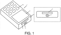
- FIG. 1 shows a schematic configuration of the reading device 1.
- the reading device 1 (mobile terminal) is a handy terminal such as that shown in FIG. 1 , for example, which is used in order to gather data for work, and can read bar codes (target information to be read) displayed on forms and perform imaging of the forms.
- the object is not limited to forms, and may be anything that includes a barcode, such as products sold in a store, or the like, for example.
- the reading device 1 is not limited to a handy terminal, and may be other information terminal devices such as a smartphone, a tablet PC (personal computer), a notebook PC, a PDA (personal digital assistant), or the like.
- the reading device 1 has: operation keys 12A; a display unit 14; an imaging unit 17; and a reading unit 18.
- the operation keys 12A are a keypad that receives operational input, and are used in order for a user to perform necessary operational input.
- Examples of operational input include: input of numbers and letters; trigger input for performing reading via the reading unit 18 and imaging via the imaging unit 17; or the like.
- the display unit 14 is configured using an LCD (liquid crystal display), ELD (electroluminescent display), or the like, and has the role of displaying necessary information to the user.
- the display unit 14 may be configured using a pressure-sensitive touch panel, an electrostatic touch panel, or the like, and may be configured so as to be able to fulfill the role of operational input.
- the display unit 14 includes a speaker that is able to output sound, and the like.
- the imaging unit 17 (camera) is configured using a digital camera that can capture still images.
- the imaging unit 17 has: a lens; an imaging element; various types of sensors; an analog processing unit; and a digital processing unit, and is able to image an object as a result of an object image from the imaging lens being formed on the imaging element.
- the reading unit 18 is a laser scanner that reads one-dimensional bar codes and includes: a light source; a light-receiving unit; a gain circuit; and a binarization circuit.
- the barcode is irradiated by a scanning light generated by swing a light source at a prescribed scanning width (scanning angle range) in a one-dimensional prescribed direction, and reflected light thereof is received by the light-receiving unit and converted into an electric signal. Then, the converted electric signal is amplified by the gain circuit, and is converted into binary data by the binarization circuit to be output.
- the reading device 1 also includes a drive unit 18A that is able to control the inclination of the reading unit 18 so as to be able to change the emission direction of the scanning light.
- the present embodiment was configured so as to incline the reading unit 18, but the present invention is not limited to this. Since it is sufficient for the device to be able to change the emission direction of the scanning light, a mirror that reflects the scanning light in a prescribed direction may be prepared, and the drive unit 18A may be configured to control the inclination of the mirror. In such a configuration, the reading unit 18 is able to change the emission direction of the scanning light without moving the reading unit 18 itself.
- the imaging unit 17 and the reading unit 18 are disposed near each other on the same surface of the reading device 1, as shown in FIG. 1 , for example.
- the reading unit 18 of the reading device it is possible, when reading a bar code using the reading unit 18 of the reading device 1, to capture an object on which a bar code is displayed at an angle of view that represents a range at which imaging is possible via the imaging unit 17.
- the device is configured to be able to simultaneously acquire the code information of the bar code and the image of the object.
- the reading unit 18 and the imaging unit 17 are disposed such that the center in the scanning width direction of the scanning light emitted from the reading unit 18 intersects the optical axis of the imaging unit 17 at a prescribed location.
- the optical axis of the imaging unit 17 represents an axis that passes through the center of the angle of view in the imaging direction.
- FIG. 2 shows the physical configuration of the reading device 1.
- the reading device 1 includes: a CPU (central processing unit) 11; an operating unit 12; RAM (random access memory) 13; the display unit 14; a storage unit 15; a communication unit 16; the imaging unit 17; the reading unit 18; and a bus 19.
- the respective units of the reading device 1 are connected via the bus 19. Since the display unit 14, imaging unit 17, and reading unit 18 are as described above, a description thereof will be omitted here.
- the CPU 11 controls the respective units of the reading device 1.
- the CPU 11 reads designated programs from among the system programs and application programs stored in storage unit 15, loads the programs into the RAM 13, and executes various types of processing in coordination with the programs loaded into the RAM 13.
- the operating unit 12 is, in other words, the operation keys 12A.
- the operating unit 12 includes a touch panel provided on the screen of the display unit 14.
- the RAM 13 is volatile memory that temporarily stores information, and has a work area for storing various types of data and programs.
- the storage unit 15 (memory) is configured to have ROM (read-only memory), flash memory, or the like, for example, and stores, in addition to the operating system, programs, applications, code information acquired via the imaging unit 17 and the reading unit 18, and the like.
- the storage unit 15 may be configured to include portable, removable memory such as an SD card, an IC (integrated circuit) card, or the like, and may include a prescribed external server storage area (not shown) when the device is connected to a network via a communication function, for example.
- the communication unit 16 includes: a wireless communication antenna; a modulation unit for transmission signals; a demodulation unit for received signals; and the like, and is able to carry out wireless communication with an access point provided on a communication network, for example.
- FIG. 3 is a block diagram that shows the functional configuration of the reading device 1.
- the reading device 1 has the following functions: a perpendicular determination function 31; a distance information acquisition function 32; a reading control function 33; an imaging control function 34; and an information management function 35.
- the perpendicular determination function 31 determines whether the optical axis of the imaging unit 17 is perpendicular with respect to the object. This is performed in order to avoid having the object be skewed when imaging via the imaging unit 17. This determination is made by the imaging unit 17 that detects an angle formed between the optical axis and the object, and by the CPU 11 that makes a determination based on the detection results.
- the present invention is not limited to using the imaging unit 17, however, and a level or the like that is able to detect inclination may be provided instead.
- the distance from the imaging unit 17 to the object is measured by the distance information acquisition function 32 to acquire distance information.
- the acquisition of the distance information is carried out by using the imaging unit 17; the present invention is not limited to this, however.
- Another type of distance measuring sensor that uses LEDs or lasers may be provided, for example.
- the user may input the distance information to the object via the operating unit 12 beforehand. In such a case, the user must perform reading and imaging while maintaining a prescribed distance from the object. However, it is no longer necessary to acquire the distance information every time, and it is also no longer necessary to set the angle of the reading unit 18, which will be described later, every time.
- the reading control function 33 sets an emission direction of the scanning light in accordance with the distance information acquired by the distance information acquisition function 32, and emits the set scanning light.
- the emission direction of the scanning light is set by setting the angle at which the reading unit 18 is inclined. This will be described in more detail using FIG. 5 .
- This angle it is possible to avoid a phenomenon in which reading of the bar code becomes impossible due to the scanning light being emitted from the front surface, and it is possible to make it more likely for the object to be within the angle of view when imaging via the imaging unit 17, which is carried out afterwards.
- the user moves the reading device 1 so as to irradiate the bar code with the scanning light.
- the reading device 1 outputs the acquired code information to the CPU 11.
- the user moves the reading device 1, it is necessary to move the reading device 1 in a direction parallel to the object. This is because it is necessary to maintain the perpendicular state determined by the perpendicular determination function 31 and the distance measured by the distance information acquisition function 32.
- the imaging control function 34 performs control such that the imaging unit 17 carries out imaging successively after the reading control function 33 has read the code information .
- the reading device 1 is configured such that reading by the user using the reading unit 18 triggers the imaging unit 17 to carry out imaging.
- the information management function 35 matches up the code information acquired via the reading unit 18 and the image acquired via the imaging by the imaging unit 17, and stores this information and the image in the storage unit 15. In addition, it is possible to call up the information stored in the storage unit 15 and display this information on the display unit 14.
- FIG. 4 shows the placement of the imaging unit 17 and the reading unit 18.
- the emission direction of the scanning light is set via the reading unit 18 being disposed so as to incline in relation to the imaging unit 17.
- the imaging unit 17 and the reading unit 18 are disposed such that the optical axis of the imaging unit 17 and the center in the scanning width direction of a scanning light 42 emitted by the reading unit 18 intersect at a distance L from the imaging unit 17. It is possible to change an angle ⁇ at which the reading unit 18 is inclined by the drive unit 18A, and the distance L at which the optical axis and the center in the scanning width direction of the scanning light 42 intersect can be changed by changing the angle ⁇ .
- the reading device 1 is configured so as to collectively acquire the code information of the bar code and the image of the object by performing imaging via the imaging unit 17 when the bar code is read by the reading unit 18.
- it can be considered in a comparative example to make the emission direction of the scanning light from the reading unit 18 and the optical axis of the imaging unit 17 be parallel as shown in FIG. 5 , but there are problems with such a configuration.
- the reading by the reading unit 18 from the front surface of the object would be performed in a state that the optical axis of the imaging unit 17 is perpendicular to the object.
- the bar code when reading the bar code using the reflected light, it becomes no longer possible to read the bar code when light is emitted from the front surface. This is because, when the angle of incidence of the light is a right angle, the light that is reflected back is extremely bright, which makes it no longer possible to correctly read the code information. This area where reading is impossible is called a "dead zone.”
- the center in the scanning width direction of the scanning light 42 from the reading unit 18 and the optical axis of the imaging unit 17, i.e., the center of an angle of view 41, are separated from each other.
- the object will not fall within the angle of view 41 of the imaging unit 17, or even if the object falls within the angle of view 41, the object is skewed toward one part of the angle of view 41, which can lead to unnatural white spaces.
- the imaging unit 17 and the reading unit 18 are disposed such that the optical axis of the imaging unit 17 and the center in the scanning width direction of the scanning light 42 from the reading unit 18 intersect.
- the reading device 1 is configured such that it is possible to change the angle ⁇ in accordance with the distance L and the distance X.
- the present embodiment is configured such that the angle ⁇ is changed by controlling the drive unit 18A via the CPU 11, it is not absolutely necessary to include the drive unit 18A, and the angle ⁇ may be changed by the user manually. In a case in which the distance L to the object is assumed ahead of time to be a prescribed value, the angle ⁇ may be matched up with the distance L without being changed.
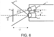
- FIGs. 6 and 7 show the relationship between the distance L to the object and the reading unit 18.
- the reading unit 18 is inclined with respect to the imaging unit 17 at an angle ⁇ 1.
- the emission direction of the scanning light 42 is set such that the optical axis and the center in the scanning width direction of the scanning light 42 intersect at the distance L1 .
- the optical axis of the imaging unit 17 and the center in the scanning width direction of the scanning light 42 intersect at the distance L1, or in other words, on the object 51. Therefore, using FIGs. 8 to 10 to explain in more detail, when the bar code is irradiated with the scanning light 42 at the time of reading the bar code displayed on the object 51, it is possible to image by the imaging unit 17 the bar code being captured at the center of the angle of view 41. In addition, the scanning light 42 irradiates the bar code from an oblique direction.
- the reading unit 18 is inclined at an angle ⁇ 2 with respect to the imaging unit 17.
- the emission direction of the scanning light 42 is set such that the optical axis and the center in the scanning width direction of the scanning light 42 intersect at the distance L2.
- the optical axis of the imaging unit 17 and the center in the scanning width direction of the scanning light 42 intersect on the object 51.
- the scanning light 42 irradiates the bar code from an oblique direction.
- FIG. 8 shows the positional relationship between the angle of view of the imaging unit 17 and the scanning light of the reading unit 18.
- the center in the scanning width direction of the scanning light 42 and the center in the scanning width direction of the angle of view 41 intersect at a point 81 at the distance L from the imaging unit 17.
- the emission direction of the scanning light 42 is set by setting the angle ⁇ of the reading unit 18 that corresponds to the distance L to the object. It is preferable that even if the distance L to the object changes, the angle ⁇ be set accordingly such that the center in the scanning width direction of the scanning light 42 and the optical axis that is the center of the angle of view 41 intersect with each other on the object, i.e., at the updated distance L.
- FIG. 9 shows an instance in which reading of the object has been actually carried out.
- FIG. 9 as an example of an object 51A, a form A, on which a bar code 52A is displayed in the lower right, is read and imaged.
- the bar code is located at the exact vertical center of the vertical angle of view 41, and thus the object 51A falls within the angle of view 41.
- the reading device 1 since the object is imaged such that the bar code is located at the vertical center of the angle of view 41, white spaces appear, depending on the position at which the bar code of the object is displayed.
- a white space has appeared at the bottom of the angle of view 41, for example. It is preferable that this white space be altered by carrying out trimming or the like.
- FIG. 10 As an example of an object 51B, a form B, on which a bar code 52B is displayed in the upper left, is read and imaged. As shown in FIG. 10 , when the scanning light 42 is aligned with the bar code 52B, it can be seen that the bar code is located at the exact vertical center of the vertical angle of view 41, and thus the object 51B falls within the angle of view 41. In FIG. 10 , since the bar code 52B is displayed in the upper left of the object 51B, a white space has appeared at the top of the angle of view 41. It is preferable that this white space be altered by carrying out trimming or the like as in FIG. 9 .
- FIG. 11 is a flow chart illustrating reading and imaging processing.
- Reading and imaging processing is processing that occurs when bar codes are read by the reading device 1 and the object on which the bar code is displayed is imaged. This processing is carried out when operational input is input by a user via the operating unit 12. In other words, when trigger keys are being pressed, for example, as the operational input, processing is carried out, and when the pressing of the trigger keys ends, processing is finished.
- the CPU 11 determines whether the optical axis of the imaging unit 17 is perpendicular with respect to the object (Step S11). In other words, the CPU 11 functions as the perpendicular determination function 31. Since the determination method was described for FIG. 3 , a description thereof is omitted here.
- the device be configured such that when it is determined that the optical axis of the imaging unit 17 is perpendicular to the object in Step S11, the user is notified by the display unit 14 outputting a notification sound.
- the notification method is not limited to this, and an LED lamp may be provided so as to light the LED lamp while it is determined that the optical axis is perpendicular to the object, for example.
- the CPU 11 When the CPU 11 has determined that the optical axis of the imaging unit 17 is perpendicular to the object (Step S11; YES), the CPU 11 acquires the distance information from the imaging unit 17 to the object (Step S12). In other words, the CPU 11 functions as the distance information acquisition function 32. Since the acquisition method was described for FIG. 3 , a description thereof is omitted here.
- the CPU 11 sets the emission direction of the scanning light by setting the angle ⁇ at which the reading unit 18 inclines based on the acquired distance information (Step S13). In other words, it is possible to set the angle ⁇ such that the center of the scanning light emitted from the reading unit 18 and the optical axis of the imaging unit 17 intersect on the object by using the acquired distance information.
- the emission of the scanning light by the reading unit 18 commences (Step S14). In other words, the CPU 11 functions as the reading control function 33.
- the user moves the reading device 1 and matches up the emitted scanning light with the bar code displayed on the object.
- the reading device 1 it is necessary to move the reading device 1 parallel to the object.
- Step S15 imaging is subsequently carried out by the imaging unit 17 (Step S16).
- the CPU 11 functions as the imaging control function 34.
- the imaging control function 34 it is possible to perform imaging such as that in FIGs. 9 and 10 in which the bar code is captured at the vertical center of the angle of view.
- the device may be configured such that, when imaging is actually carried out, the emission of the scanning light stops. As a result, it is possible to avoid the scanning light from being captured in the acquired image.
- the code information of the bar code acquired by the reading unit 18 and the image acquired by the imaging unit 17 are recorded in the storage unit 15 as associated with each other (Step S17).
- the CPU 11 functions as the information management function 35.
- the reading device 1 includes: the imaging unit 17 that acquires an image by imaging an object; and the reading unit 18 that emits a scanning light formed of a light beam that has a scanning width in a prescribed one-dimensional direction by using a light source that generates the light beam, and reads code information included in the object.
- the imaging unit 17 and the reading unit 18 are disposed such that the center in the scanning width direction of the scanning light and the optical axis of the imaging unit 17 intersect at a prescribed location.
- the placement of the imaging unit 17 and the reading unit 18 of the reading device 1 is determined in accordance with the distance between the reading unit 18 and the imaging unit 17 and the distance between the imaging unit 17 and the object. As a result, it is possible to determine the placement of the imaging unit and the reading unit.
- the reading device 1 includes: the imaging unit 17 that acquires an image by imaging an object; the reading unit 18 that emits a scanning light formed of a light beam that has a scanning width in a prescribed one-dimensional direction by using a light source that generates the light beam, and reads code information included in the object; a determination unit that determines whether the optical axis of the imaging unit 17 and the object are perpendicular; and an acquisition unit that, when it is determined that the optical axis of the imaging unit 17 and the object are perpendicular, acquires distance information indicating the distance from the imaging unit 17 to the object.
- the reading unit 18 changes the emission direction of the scanning light in accordance with the distance information acquired by the acquisition unit so that the center in the scanning width direction of the scanning light and the optical axis of the imaging unit 17 intersect on the object. Thus, it is possible to more easily ensure that the object is captured in the angle of view.
- the reading device 1 further includes the notification unit that performs notification when it is determined by the determination unit that the optical axis of the imaging unit 17 and the object are perpendicular. Thus, the user can be notified of the status.
- the reading device 1 acquires the distance information indicating the distance from the imaging unit 17 to the object via operational input by the user. Thus, it is possible to easily acquire the necessary distance information.
- the reading device 1 acquires the distance information indicating the distance from the imaging unit 17 to the object by a distance measuring sensor. Thus, it is possible to easily acquire the necessary distance information.
- the imaging unit 17 and the reading unit 18 were disposed and arranged in the vertical direction; however, the present invention is not limited to this, and the imaging unit 17 and reading unit 18 may be disposed and arranged in another direction. In such a case, similar to the embodiment above, it is preferable that the reading unit 18 and the imaging unit 17 be disposed such that the center in the scanning width direction of the scanning light of the reading unit 18 overlaps the optical axis that is the center of the angle of view of the imaging unit 17.
- the placement of the imaging unit 17 and the reading unit 18 was described. However, it is not absolutely necessary that the imaging unit 17 and the reading unit 18 be disposed as described above, and it is sufficient that the relationship between the angle of view of the imaging unit 17 and the scanning light emitted by the reading unit 18 are realized as described in the above-mentioned embodiment. Thus, it is possible to realize the reading device 1 without specifically limiting the placement of the imaging unit 17 and the reading unit 18 themselves by adjusting the angle of view of the imaging unit 17 and the emission direction of the scanning light of the reading unit 18 by using a mirror, for example.
- the imaging unit 17 and the reading unit 18 were disposed such that the bar code is located at the center of the angle of view at the time of imaging; however, the present invention is not limited to this.
- the present invention may be configured such that the object fills the angle of view when imaging is performed at the time of reading the bar code by determining the placement of the imaging unit 17 and the reading unit 18 by additionally taking into account the size of the object and the location at which the bar code is displayed, for example.
- the reading unit 18 was described as a laser scanner in the above-mentioned embodiment, the reading unit 18 may be another type of one-dimensional bar code scanner.
Landscapes
- Physics & Mathematics (AREA)
- Engineering & Computer Science (AREA)
- Electromagnetism (AREA)
- Artificial Intelligence (AREA)
- Health & Medical Sciences (AREA)
- General Health & Medical Sciences (AREA)
- Toxicology (AREA)
- Computer Vision & Pattern Recognition (AREA)
- General Physics & Mathematics (AREA)
- Theoretical Computer Science (AREA)
- Signal Processing (AREA)
- Multimedia (AREA)
- Image Input (AREA)
- Facsimile Scanning Arrangements (AREA)
- Telephone Function (AREA)
- Length Measuring Devices By Optical Means (AREA)
Claims (9)
- Lesevorrichtung (1), umfassend:eine Kamera (17), die ein Bild durch Abbildung eines Objekts erlangt; undeinen Scanner (18), der einen Lichtstrahl in Richtung des Objekts auf eine Scanweise aussendet, um ein Scanlicht mit einem vorgegebenen Scanwinkelbereich in einer eindimensional vorgegebenen Richtung auszusenden, und der das durch das Objekt reflektierte Scanlicht erfasst, um so eine auf einer Oberfläche des Objekts angezeigte Zielinformation zu erlangen, wobei eine Aussendungsrichtung des Scanlichts änderbar ist, dadurch gekennzeichnet, dass die Lesevorrichtung (1) ferner Folgendes umfasst:
einen Prozessor (11), der Folgendes durchführt:Bestimmen, ob die Oberfläche des Objekts und eine optische Achse der Kamera (17) senkrecht zueinander stehen oder nicht;wenn für die Oberfläche des Objekts und die optische Achse der Kamera (17) bestimmt wird, dass sie senkrecht zueinander stehen, Erlangen von Abstandsinformationen, die einen Abstand von der Kamera (17) zu dem Objekt angeben; undVeranlassen des Scanners (18), die Aussendungsrichtung des Scanlichts gemäß den erlangten Abstandsinformationen so zu ändern, dass sich eine Mittellinie des vorgegebenen Scanwinkelbereichs des Scanlichts und die optische Achse der Kamera (17) auf der Oberfläche des Objekts miteinander schneiden. - Lesevorrichtung (1) nach Anspruch 1, wobei der Prozessor (11) ferner Folgendes durchführt:Veranlassen des Scanners (18), das Scanlicht zu dem Objekt in der geänderten Aussendungsrichtung auszusenden, um so die auf der Oberfläche des Objekts angezeigten Zielinformationen zu erlangen; unddanach, Veranlassen der Kamera (17), das Objekt abzubilden.
- Lesevorrichtung (1) nach Anspruch 2, ferner umfassend einen Speicher,
wobei der Prozessor (11) den Speicher dazu veranlasst, die durch den Scanner (18) erlangten Zielinformationen und das durch die Kamera (17) erlangte Bild als miteinander assoziiert zu speichern. - Lesevorrichtung (1) nach Anspruch 2, wobei es der Prozessor (11) veranlasst, dass ein Benutzer informiert wird, wenn der Prozessor (11) bestimmt, dass die Oberfläche des Objekts und die optische Achse der Kamera (17) senkrecht zueinander stehen.
- Lesevorrichtung (1) nach Anspruch 2, wobei die Abstandsinformationen über einen Betriebseingang eines Benutzers in den Prozessor (11) eingegeben werden.
- Lesevorrichtung (1) nach Anspruch 2, ferner umfassend einen Abstandsmesssensor, der den Abstand zu dem Objekt erfasst, um die Abstandsinformationen zu erzeugen.
- Lesevorrichtung (1) nach Anspruch 2, wobei der Prozessor (11) die Abstandsinformationen, die den Abstand von der Kamera (17) zu dem Objekt angeben, durch Veranlassen der Kamera (17), das Objekt abzubilden, und Analysieren des Bildes des Objekts erlangt.
- Leseverfahren, ausgeführt durch eine Lesevorrichtung (1), wobei die Lesevorrichtung (1) Folgendes umfasst:eine Kamera (17), die ein Bild durch Abbildung eines Objekts erlangt; undeinen Scanner (18), der einen Lichtstrahl in Richtung des Objekts auf eine Scanweise aussendet, um ein Scanlicht mit einem vorgegebenen Scanwinkelbereich in einer eindimensional vorgegebenen Richtung auszusenden, und der das durch das Objekt reflektierte Scanlicht erfasst, um so eine auf einer Oberfläche des Objekts angezeigte Zielinformation zu erlangen, wobei eine Aussendungsrichtung des Scanlichts änderbar ist; dadurch gekennzeichnet, dassdas Verfahren Folgendes umfasst:Bestimmen, ob die Oberfläche des Objekts und eine optische Achse der Kamera (17) senkrecht zueinander stehen oder nicht;wenn für die Oberfläche des Objekts und die optische Achse der Kamera (17) bestimmt wird, dass sie senkrecht zueinander stehen, Erlangen von Abstandsinformationen, die einen Abstand von der Kamera (17) zu dem Objekt angeben; undVeranlassen des Scanners (18), die Aussendungsrichtung des Scanlichts gemäß den erlangten Abstandsinformationen so zu ändern, dass sich eine Mittellinie des vorgegebenen Scanwinkelbereichs des Scanlichts und die optische Achse der Kamera (17) auf der Oberfläche des Objekts miteinander schneiden.
- Nichtflüchtiges, computerlesbares Aufzeichnungsmedium, das ein durch einen Prozessor (11) einer Lesevorrichtung (1) ausführbares Programm speichert, wobei die Lesevorrichtung (1) Folgendes umfasst:eine Kamera (17), die ein Bild durch Abbildung eines Objekts erlangt; undeinen Scanner (18), der einen Lichtstrahl in Richtung des Objekts auf eine Scanweise aussendet, um ein Scanlicht mit einem vorgegebenen Scanwinkelbereich in einer eindimensional vorgegebenen Richtung auszusenden, und der das durch das Objekt reflektierte Scanlicht erfasst, um so eine auf einer Oberfläche des Objekts angezeigte Zielinformation zu erlangen, wobei eine Aussendungsrichtung des Scanlichts änderbar ist; dadurch gekennzeichnet, dassdas Programm den Prozessor (11) dazu veranlasst, Folgendes durchzuführen:Bestimmen, ob die Oberfläche des Objekts und eine optische Achse der Kamera (17) senkrecht zueinander stehen oder nicht;wenn für die Oberfläche des Objekts und die optische Achse der Kamera (17) bestimmt wird, dass sie senkrecht zueinander stehen, Erlangen von Abstandsinformationen, die einen Abstand von der Kamera (17) zu dem Objekt angeben; undVeranlassen des Scanners (18), die Aussendungsrichtung des Scanlichts gemäß den erlangten Abstandsinformationen so zu ändern, dass sich eine Mittellinie des vorgegebenen Scanwinkelbereichs des Scanlichts und die optische Achse der Kamera (17) auf der Oberfläche des Objekts miteinander schneiden.
Applications Claiming Priority (1)
| Application Number | Priority Date | Filing Date | Title |
|---|---|---|---|
| JP2017037911A JP6635073B2 (ja) | 2017-03-01 | 2017-03-01 | 読取装置 |
Publications (2)
| Publication Number | Publication Date |
|---|---|
| EP3370403A1 EP3370403A1 (de) | 2018-09-05 |
| EP3370403B1 true EP3370403B1 (de) | 2020-04-22 |
Family
ID=61526659
Family Applications (1)
| Application Number | Title | Priority Date | Filing Date |
|---|---|---|---|
| EP18159284.1A Active EP3370403B1 (de) | 2017-03-01 | 2018-02-28 | Lesevorrichtung und mobiles endgerät |
Country Status (4)
| Country | Link |
|---|---|
| US (1) | US10489621B2 (de) |
| EP (1) | EP3370403B1 (de) |
| JP (1) | JP6635073B2 (de) |
| CN (1) | CN108537078B (de) |
Families Citing this family (7)
| Publication number | Priority date | Publication date | Assignee | Title |
|---|---|---|---|---|
| CN109615360A (zh) * | 2018-09-29 | 2019-04-12 | 阿里巴巴集团控股有限公司 | 一种图形编码展示方法和装置 |
| CN110598502B (zh) * | 2019-08-06 | 2020-10-23 | 珠海格力电器股份有限公司 | 一种无线扫码自动拍摄的方法及系统 |
| EP4031832A4 (de) * | 2019-09-17 | 2023-10-18 | Carbon Autonomous Robotic Systems Inc. | Autonome laser-unkrautvernichtung |
| JP2022035393A (ja) * | 2020-08-20 | 2022-03-04 | 東芝テック株式会社 | 商品読取装置 |
| US12270903B2 (en) | 2021-03-17 | 2025-04-08 | Carbon Autonomous Robotic Systems Inc. | Systems and methods for point to point object matching and targeting |
| CA3229766A1 (en) | 2021-11-02 | 2023-05-11 | Carbon Autonomous Robotic Systems Inc. | High intensity illumination systems and methods of use thereof |
| DE102022116032B3 (de) * | 2022-06-28 | 2023-09-07 | Sick Ag | Lesevorrichtung zum berührungslosen Auslesen von Informationen auf Objekten und Verfahren zur Absicherung einer solchen Lesevorrichtung |
Family Cites Families (13)
| Publication number | Priority date | Publication date | Assignee | Title |
|---|---|---|---|---|
| WO1996013797A2 (en) * | 1994-10-25 | 1996-05-09 | United Parcel Service Of America, Inc. | Method and apparatus for a portable non-contact label imager |
| US7137555B2 (en) * | 2000-02-28 | 2006-11-21 | Psc Scanning, Inc. | Multi-format bar code reader |
| JP4403750B2 (ja) * | 2003-08-12 | 2010-01-27 | カシオ計算機株式会社 | コード読取装置 |
| JP4257850B2 (ja) * | 2004-03-03 | 2009-04-22 | パナソニック株式会社 | 複合型コード読取装置 |
| JP2009093424A (ja) * | 2007-10-09 | 2009-04-30 | Toshiba Tec Corp | データコード読取装置 |
| US8366006B2 (en) * | 2010-12-22 | 2013-02-05 | Ncr Corporation | Combined laser and imaging scanner |
| US8556176B2 (en) * | 2011-09-26 | 2013-10-15 | Metrologic Instruments, Inc. | Method of and apparatus for managing and redeeming bar-coded coupons displayed from the light emitting display surfaces of information display devices |
| US9016576B2 (en) * | 2012-05-21 | 2015-04-28 | Metrologic Instruments, Inc. | Laser scanning code symbol reading system providing improved control over the length and intensity characteristics of a laser scan line projected therefrom using laser source blanking control |
| US9075801B2 (en) * | 2013-01-18 | 2015-07-07 | Nokia Technologies Oy | Method and apparatus for sharing content via encoded data representations |
| US9311514B2 (en) * | 2014-03-27 | 2016-04-12 | Ncr Corporation | Imaging barcode scanner with multiple independent fields of view |
| US10073999B2 (en) * | 2014-10-09 | 2018-09-11 | The Code Corporation | Barcode-reading system |
| CN204480263U (zh) * | 2015-02-13 | 2015-07-15 | 西安电子科技大学 | 一种集成微型摄像头的光学条码扫描器 |
| CN205809876U (zh) * | 2016-02-20 | 2016-12-14 | 深圳市欣视景科技股份有限公司 | 一种快递包标识码扫描装置 |
-
2017
- 2017-03-01 JP JP2017037911A patent/JP6635073B2/ja active Active
-
2018
- 2018-02-27 US US15/906,714 patent/US10489621B2/en active Active
- 2018-02-27 CN CN201810161825.XA patent/CN108537078B/zh active Active
- 2018-02-28 EP EP18159284.1A patent/EP3370403B1/de active Active
Non-Patent Citations (1)
| Title |
|---|
| None * |
Also Published As
| Publication number | Publication date |
|---|---|
| US10489621B2 (en) | 2019-11-26 |
| US20180253577A1 (en) | 2018-09-06 |
| JP6635073B2 (ja) | 2020-01-22 |
| CN108537078A (zh) | 2018-09-14 |
| CN108537078B (zh) | 2021-01-12 |
| JP2018147005A (ja) | 2018-09-20 |
| EP3370403A1 (de) | 2018-09-05 |
Similar Documents
| Publication | Publication Date | Title |
|---|---|---|
| EP3370403B1 (de) | Lesevorrichtung und mobiles endgerät | |
| US9729744B2 (en) | System and method of border detection on a document and for producing an image of the document | |
| EP3040906B1 (de) | Visuelle rückmeldung für codeleser | |
| EP2507741B1 (de) | Auf bildgebung basierender scanner mit grenzliniensuche zur bilderfassung | |
| US10515249B2 (en) | Optical information reading device | |
| CN205354047U (zh) | 一种标记读取终端 | |
| US10372954B2 (en) | Method for reading indicia off a display of a mobile device | |
| US9800749B1 (en) | Arrangement for, and method of, expeditiously adjusting reading parameters of an imaging reader based on target distance | |
| US8903201B2 (en) | Method and apparatus for enhanced document capture | |
| JP2005202930A (ja) | 光学情報読取装置 | |
| JP7436509B2 (ja) | 情報処理装置、撮像装置、情報処理方法、及びプログラム | |
| CN114761757B (zh) | 信息处理装置、信息处理方法及存储介质 | |
| AU2020374767B2 (en) | Systems and methods for user choice of barcode scanning range | |
| KR102079697B1 (ko) | 판독장치, 프로그램 및 유닛 | |
| EP3301616B1 (de) | Belegverarbeitungsvorrichtung, belegverarbeitungsverfahren und aufzeichnungsmedium | |
| US10223626B2 (en) | High ambient light electronic screen communication method | |
| US8292181B1 (en) | Apparatus and system for a hybrid optical code scanner | |
| US8479995B2 (en) | Hybrid optical code scanner and system | |
| JP5888199B2 (ja) | バーコード読取装置 | |
| CN102782699A (zh) | 在有限工作距离范围具有自动聚焦的数据捕获终端 | |
| JP2008176636A (ja) | 光学情報読取装置 |
Legal Events
| Date | Code | Title | Description |
|---|---|---|---|
| PUAI | Public reference made under article 153(3) epc to a published international application that has entered the european phase |
Free format text: ORIGINAL CODE: 0009012 |
|
| STAA | Information on the status of an ep patent application or granted ep patent |
Free format text: STATUS: REQUEST FOR EXAMINATION WAS MADE |
|
| 17P | Request for examination filed |
Effective date: 20180228 |
|
| AK | Designated contracting states |
Kind code of ref document: A1 Designated state(s): AL AT BE BG CH CY CZ DE DK EE ES FI FR GB GR HR HU IE IS IT LI LT LU LV MC MK MT NL NO PL PT RO RS SE SI SK SM TR |
|
| AX | Request for extension of the european patent |
Extension state: BA ME |
|
| GRAP | Despatch of communication of intention to grant a patent |
Free format text: ORIGINAL CODE: EPIDOSNIGR1 |
|
| STAA | Information on the status of an ep patent application or granted ep patent |
Free format text: STATUS: GRANT OF PATENT IS INTENDED |
|
| INTG | Intention to grant announced |
Effective date: 20191028 |
|
| GRAS | Grant fee paid |
Free format text: ORIGINAL CODE: EPIDOSNIGR3 |
|
| GRAA | (expected) grant |
Free format text: ORIGINAL CODE: 0009210 |
|
| STAA | Information on the status of an ep patent application or granted ep patent |
Free format text: STATUS: THE PATENT HAS BEEN GRANTED |
|
| AK | Designated contracting states |
Kind code of ref document: B1 Designated state(s): AL AT BE BG CH CY CZ DE DK EE ES FI FR GB GR HR HU IE IS IT LI LT LU LV MC MK MT NL NO PL PT RO RS SE SI SK SM TR |
|
| REG | Reference to a national code |
Ref country code: CH Ref legal event code: EP |
|
| REG | Reference to a national code |
Ref country code: DE Ref legal event code: R096 Ref document number: 602018003863 Country of ref document: DE |
|
| REG | Reference to a national code |
Ref country code: IE Ref legal event code: FG4D |
|
| REG | Reference to a national code |
Ref country code: AT Ref legal event code: REF Ref document number: 1261677 Country of ref document: AT Kind code of ref document: T Effective date: 20200515 |
|
| REG | Reference to a national code |
Ref country code: LT Ref legal event code: MG4D |
|
| REG | Reference to a national code |
Ref country code: NL Ref legal event code: MP Effective date: 20200422 |
|
| PG25 | Lapsed in a contracting state [announced via postgrant information from national office to epo] |
Ref country code: FI Free format text: LAPSE BECAUSE OF FAILURE TO SUBMIT A TRANSLATION OF THE DESCRIPTION OR TO PAY THE FEE WITHIN THE PRESCRIBED TIME-LIMIT Effective date: 20200422 Ref country code: NO Free format text: LAPSE BECAUSE OF FAILURE TO SUBMIT A TRANSLATION OF THE DESCRIPTION OR TO PAY THE FEE WITHIN THE PRESCRIBED TIME-LIMIT Effective date: 20200722 Ref country code: GR Free format text: LAPSE BECAUSE OF FAILURE TO SUBMIT A TRANSLATION OF THE DESCRIPTION OR TO PAY THE FEE WITHIN THE PRESCRIBED TIME-LIMIT Effective date: 20200723 Ref country code: IS Free format text: LAPSE BECAUSE OF FAILURE TO SUBMIT A TRANSLATION OF THE DESCRIPTION OR TO PAY THE FEE WITHIN THE PRESCRIBED TIME-LIMIT Effective date: 20200822 Ref country code: LT Free format text: LAPSE BECAUSE OF FAILURE TO SUBMIT A TRANSLATION OF THE DESCRIPTION OR TO PAY THE FEE WITHIN THE PRESCRIBED TIME-LIMIT Effective date: 20200422 Ref country code: PT Free format text: LAPSE BECAUSE OF FAILURE TO SUBMIT A TRANSLATION OF THE DESCRIPTION OR TO PAY THE FEE WITHIN THE PRESCRIBED TIME-LIMIT Effective date: 20200824 Ref country code: SE Free format text: LAPSE BECAUSE OF FAILURE TO SUBMIT A TRANSLATION OF THE DESCRIPTION OR TO PAY THE FEE WITHIN THE PRESCRIBED TIME-LIMIT Effective date: 20200422 Ref country code: NL Free format text: LAPSE BECAUSE OF FAILURE TO SUBMIT A TRANSLATION OF THE DESCRIPTION OR TO PAY THE FEE WITHIN THE PRESCRIBED TIME-LIMIT Effective date: 20200422 |
|
| REG | Reference to a national code |
Ref country code: AT Ref legal event code: MK05 Ref document number: 1261677 Country of ref document: AT Kind code of ref document: T Effective date: 20200422 |
|
| PG25 | Lapsed in a contracting state [announced via postgrant information from national office to epo] |
Ref country code: RS Free format text: LAPSE BECAUSE OF FAILURE TO SUBMIT A TRANSLATION OF THE DESCRIPTION OR TO PAY THE FEE WITHIN THE PRESCRIBED TIME-LIMIT Effective date: 20200422 Ref country code: BG Free format text: LAPSE BECAUSE OF FAILURE TO SUBMIT A TRANSLATION OF THE DESCRIPTION OR TO PAY THE FEE WITHIN THE PRESCRIBED TIME-LIMIT Effective date: 20200722 Ref country code: HR Free format text: LAPSE BECAUSE OF FAILURE TO SUBMIT A TRANSLATION OF THE DESCRIPTION OR TO PAY THE FEE WITHIN THE PRESCRIBED TIME-LIMIT Effective date: 20200422 Ref country code: LV Free format text: LAPSE BECAUSE OF FAILURE TO SUBMIT A TRANSLATION OF THE DESCRIPTION OR TO PAY THE FEE WITHIN THE PRESCRIBED TIME-LIMIT Effective date: 20200422 |
|
| PG25 | Lapsed in a contracting state [announced via postgrant information from national office to epo] |
Ref country code: AL Free format text: LAPSE BECAUSE OF FAILURE TO SUBMIT A TRANSLATION OF THE DESCRIPTION OR TO PAY THE FEE WITHIN THE PRESCRIBED TIME-LIMIT Effective date: 20200422 |
|
| REG | Reference to a national code |
Ref country code: DE Ref legal event code: R097 Ref document number: 602018003863 Country of ref document: DE |
|
| PG25 | Lapsed in a contracting state [announced via postgrant information from national office to epo] |
Ref country code: SM Free format text: LAPSE BECAUSE OF FAILURE TO SUBMIT A TRANSLATION OF THE DESCRIPTION OR TO PAY THE FEE WITHIN THE PRESCRIBED TIME-LIMIT Effective date: 20200422 Ref country code: EE Free format text: LAPSE BECAUSE OF FAILURE TO SUBMIT A TRANSLATION OF THE DESCRIPTION OR TO PAY THE FEE WITHIN THE PRESCRIBED TIME-LIMIT Effective date: 20200422 Ref country code: AT Free format text: LAPSE BECAUSE OF FAILURE TO SUBMIT A TRANSLATION OF THE DESCRIPTION OR TO PAY THE FEE WITHIN THE PRESCRIBED TIME-LIMIT Effective date: 20200422 Ref country code: DK Free format text: LAPSE BECAUSE OF FAILURE TO SUBMIT A TRANSLATION OF THE DESCRIPTION OR TO PAY THE FEE WITHIN THE PRESCRIBED TIME-LIMIT Effective date: 20200422 Ref country code: ES Free format text: LAPSE BECAUSE OF FAILURE TO SUBMIT A TRANSLATION OF THE DESCRIPTION OR TO PAY THE FEE WITHIN THE PRESCRIBED TIME-LIMIT Effective date: 20200422 Ref country code: CZ Free format text: LAPSE BECAUSE OF FAILURE TO SUBMIT A TRANSLATION OF THE DESCRIPTION OR TO PAY THE FEE WITHIN THE PRESCRIBED TIME-LIMIT Effective date: 20200422 Ref country code: IT Free format text: LAPSE BECAUSE OF FAILURE TO SUBMIT A TRANSLATION OF THE DESCRIPTION OR TO PAY THE FEE WITHIN THE PRESCRIBED TIME-LIMIT Effective date: 20200422 Ref country code: RO Free format text: LAPSE BECAUSE OF FAILURE TO SUBMIT A TRANSLATION OF THE DESCRIPTION OR TO PAY THE FEE WITHIN THE PRESCRIBED TIME-LIMIT Effective date: 20200422 |
|
| PG25 | Lapsed in a contracting state [announced via postgrant information from national office to epo] |
Ref country code: PL Free format text: LAPSE BECAUSE OF FAILURE TO SUBMIT A TRANSLATION OF THE DESCRIPTION OR TO PAY THE FEE WITHIN THE PRESCRIBED TIME-LIMIT Effective date: 20200422 Ref country code: SK Free format text: LAPSE BECAUSE OF FAILURE TO SUBMIT A TRANSLATION OF THE DESCRIPTION OR TO PAY THE FEE WITHIN THE PRESCRIBED TIME-LIMIT Effective date: 20200422 |
|
| PLBE | No opposition filed within time limit |
Free format text: ORIGINAL CODE: 0009261 |
|
| STAA | Information on the status of an ep patent application or granted ep patent |
Free format text: STATUS: NO OPPOSITION FILED WITHIN TIME LIMIT |
|
| 26N | No opposition filed |
Effective date: 20210125 |
|
| PG25 | Lapsed in a contracting state [announced via postgrant information from national office to epo] |
Ref country code: SI Free format text: LAPSE BECAUSE OF FAILURE TO SUBMIT A TRANSLATION OF THE DESCRIPTION OR TO PAY THE FEE WITHIN THE PRESCRIBED TIME-LIMIT Effective date: 20200422 |
|
| PG25 | Lapsed in a contracting state [announced via postgrant information from national office to epo] |
Ref country code: MC Free format text: LAPSE BECAUSE OF FAILURE TO SUBMIT A TRANSLATION OF THE DESCRIPTION OR TO PAY THE FEE WITHIN THE PRESCRIBED TIME-LIMIT Effective date: 20200422 |
|
| REG | Reference to a national code |
Ref country code: BE Ref legal event code: MM Effective date: 20210228 |
|
| PG25 | Lapsed in a contracting state [announced via postgrant information from national office to epo] |
Ref country code: LI Free format text: LAPSE BECAUSE OF NON-PAYMENT OF DUE FEES Effective date: 20210228 Ref country code: LU Free format text: LAPSE BECAUSE OF NON-PAYMENT OF DUE FEES Effective date: 20210228 Ref country code: CH Free format text: LAPSE BECAUSE OF NON-PAYMENT OF DUE FEES Effective date: 20210228 |
|
| PG25 | Lapsed in a contracting state [announced via postgrant information from national office to epo] |
Ref country code: IE Free format text: LAPSE BECAUSE OF NON-PAYMENT OF DUE FEES Effective date: 20210228 |
|
| PG25 | Lapsed in a contracting state [announced via postgrant information from national office to epo] |
Ref country code: BE Free format text: LAPSE BECAUSE OF NON-PAYMENT OF DUE FEES Effective date: 20210228 |
|
| PG25 | Lapsed in a contracting state [announced via postgrant information from national office to epo] |
Ref country code: CY Free format text: LAPSE BECAUSE OF FAILURE TO SUBMIT A TRANSLATION OF THE DESCRIPTION OR TO PAY THE FEE WITHIN THE PRESCRIBED TIME-LIMIT Effective date: 20200422 |
|
| PG25 | Lapsed in a contracting state [announced via postgrant information from national office to epo] |
Ref country code: HU Free format text: LAPSE BECAUSE OF FAILURE TO SUBMIT A TRANSLATION OF THE DESCRIPTION OR TO PAY THE FEE WITHIN THE PRESCRIBED TIME-LIMIT; INVALID AB INITIO Effective date: 20180228 |
|
| PG25 | Lapsed in a contracting state [announced via postgrant information from national office to epo] |
Ref country code: MK Free format text: LAPSE BECAUSE OF FAILURE TO SUBMIT A TRANSLATION OF THE DESCRIPTION OR TO PAY THE FEE WITHIN THE PRESCRIBED TIME-LIMIT Effective date: 20200422 |
|
| PG25 | Lapsed in a contracting state [announced via postgrant information from national office to epo] |
Ref country code: TR Free format text: LAPSE BECAUSE OF FAILURE TO SUBMIT A TRANSLATION OF THE DESCRIPTION OR TO PAY THE FEE WITHIN THE PRESCRIBED TIME-LIMIT Effective date: 20200422 |
|
| PG25 | Lapsed in a contracting state [announced via postgrant information from national office to epo] |
Ref country code: MT Free format text: LAPSE BECAUSE OF FAILURE TO SUBMIT A TRANSLATION OF THE DESCRIPTION OR TO PAY THE FEE WITHIN THE PRESCRIBED TIME-LIMIT Effective date: 20200422 |
|
| PGFP | Annual fee paid to national office [announced via postgrant information from national office to epo] |
Ref country code: FR Payment date: 20241231 Year of fee payment: 8 |
|
| PGFP | Annual fee paid to national office [announced via postgrant information from national office to epo] |
Ref country code: DE Payment date: 20241231 Year of fee payment: 8 |
|
| PGFP | Annual fee paid to national office [announced via postgrant information from national office to epo] |
Ref country code: GB Payment date: 20250102 Year of fee payment: 8 |