EP3370334B1 - Power control device, control method for power control device, power control system and control method for power control system - Google Patents
Power control device, control method for power control device, power control system and control method for power control system Download PDFInfo
- Publication number
- EP3370334B1 EP3370334B1 EP16859317.6A EP16859317A EP3370334B1 EP 3370334 B1 EP3370334 B1 EP 3370334B1 EP 16859317 A EP16859317 A EP 16859317A EP 3370334 B1 EP3370334 B1 EP 3370334B1
- Authority
- EP
- European Patent Office
- Prior art keywords
- relay
- voltage
- power
- independent operation
- power control
- Prior art date
- Legal status (The legal status is an assumption and is not a legal conclusion. Google has not performed a legal analysis and makes no representation as to the accuracy of the status listed.)
- Active
Links
- 238000000034 method Methods 0.000 title claims description 60
- 230000007935 neutral effect Effects 0.000 claims description 14
- 238000003466 welding Methods 0.000 description 42
- 238000010248 power generation Methods 0.000 description 40
- 210000004027 cell Anatomy 0.000 description 39
- 230000008569 process Effects 0.000 description 36
- 210000000352 storage cell Anatomy 0.000 description 29
- 238000001514 detection method Methods 0.000 description 28
- 238000010586 diagram Methods 0.000 description 13
- 238000004891 communication Methods 0.000 description 11
- 239000000446 fuel Substances 0.000 description 11
- 239000007789 gas Substances 0.000 description 8
- 230000005611 electricity Effects 0.000 description 6
- 238000006243 chemical reaction Methods 0.000 description 4
- 230000001360 synchronised effect Effects 0.000 description 4
- 238000009434 installation Methods 0.000 description 3
- 230000002457 bidirectional effect Effects 0.000 description 2
- 230000005540 biological transmission Effects 0.000 description 2
- 230000007257 malfunction Effects 0.000 description 2
- 230000007246 mechanism Effects 0.000 description 2
- 230000002093 peripheral effect Effects 0.000 description 2
- 230000009467 reduction Effects 0.000 description 2
- 230000004044 response Effects 0.000 description 2
- 230000035939 shock Effects 0.000 description 2
- UFHFLCQGNIYNRP-UHFFFAOYSA-N Hydrogen Chemical compound [H][H] UFHFLCQGNIYNRP-UHFFFAOYSA-N 0.000 description 1
- HBBGRARXTFLTSG-UHFFFAOYSA-N Lithium ion Chemical compound [Li+] HBBGRARXTFLTSG-UHFFFAOYSA-N 0.000 description 1
- 238000004378 air conditioning Methods 0.000 description 1
- QVGXLLKOCUKJST-UHFFFAOYSA-N atomic oxygen Chemical compound [O] QVGXLLKOCUKJST-UHFFFAOYSA-N 0.000 description 1
- 230000008901 benefit Effects 0.000 description 1
- 239000003990 capacitor Substances 0.000 description 1
- 238000009429 electrical wiring Methods 0.000 description 1
- 239000001257 hydrogen Substances 0.000 description 1
- 229910052739 hydrogen Inorganic materials 0.000 description 1
- 229910001416 lithium ion Inorganic materials 0.000 description 1
- 238000012423 maintenance Methods 0.000 description 1
- 239000011159 matrix material Substances 0.000 description 1
- 229910052987 metal hydride Inorganic materials 0.000 description 1
- 239000007769 metal material Substances 0.000 description 1
- 229910021421 monocrystalline silicon Inorganic materials 0.000 description 1
- 239000001301 oxygen Substances 0.000 description 1
- 229910052760 oxygen Inorganic materials 0.000 description 1
- 229910021420 polycrystalline silicon Inorganic materials 0.000 description 1
- 239000007787 solid Substances 0.000 description 1
- 239000010409 thin film Substances 0.000 description 1
- 230000009466 transformation Effects 0.000 description 1
Images


Classifications
-
- H—ELECTRICITY
- H01—ELECTRIC ELEMENTS
- H01H—ELECTRIC SWITCHES; RELAYS; SELECTORS; EMERGENCY PROTECTIVE DEVICES
- H01H3/00—Mechanisms for operating contacts
- H01H3/001—Means for preventing or breaking contact-welding
-
- G—PHYSICS
- G01—MEASURING; TESTING
- G01R—MEASURING ELECTRIC VARIABLES; MEASURING MAGNETIC VARIABLES
- G01R19/00—Arrangements for measuring currents or voltages or for indicating presence or sign thereof
- G01R19/165—Indicating that current or voltage is either above or below a predetermined value or within or outside a predetermined range of values
- G01R19/16504—Indicating that current or voltage is either above or below a predetermined value or within or outside a predetermined range of values characterised by the components employed
- G01R19/16509—Indicating that current or voltage is either above or below a predetermined value or within or outside a predetermined range of values characterised by the components employed using electromagnetic relays, e.g. reed relay
-
- G—PHYSICS
- G01—MEASURING; TESTING
- G01R—MEASURING ELECTRIC VARIABLES; MEASURING MAGNETIC VARIABLES
- G01R31/00—Arrangements for testing electric properties; Arrangements for locating electric faults; Arrangements for electrical testing characterised by what is being tested not provided for elsewhere
- G01R31/327—Testing of circuit interrupters, switches or circuit-breakers
- G01R31/3277—Testing of circuit interrupters, switches or circuit-breakers of low voltage devices, e.g. domestic or industrial devices, such as motor protections, relays, rotation switches
- G01R31/3278—Testing of circuit interrupters, switches or circuit-breakers of low voltage devices, e.g. domestic or industrial devices, such as motor protections, relays, rotation switches of relays, solenoids or reed switches
-
- H—ELECTRICITY
- H01—ELECTRIC ELEMENTS
- H01H—ELECTRIC SWITCHES; RELAYS; SELECTORS; EMERGENCY PROTECTIVE DEVICES
- H01H47/00—Circuit arrangements not adapted to a particular application of the relay and designed to obtain desired operating characteristics or to provide energising current
- H01H47/002—Monitoring or fail-safe circuits
-
- H—ELECTRICITY
- H02—GENERATION; CONVERSION OR DISTRIBUTION OF ELECTRIC POWER
- H02J—CIRCUIT ARRANGEMENTS OR SYSTEMS FOR SUPPLYING OR DISTRIBUTING ELECTRIC POWER; SYSTEMS FOR STORING ELECTRIC ENERGY
- H02J3/00—Circuit arrangements for ac mains or ac distribution networks
- H02J3/38—Arrangements for parallely feeding a single network by two or more generators, converters or transformers
- H02J3/381—Dispersed generators
-
- H—ELECTRICITY
- H02—GENERATION; CONVERSION OR DISTRIBUTION OF ELECTRIC POWER
- H02M—APPARATUS FOR CONVERSION BETWEEN AC AND AC, BETWEEN AC AND DC, OR BETWEEN DC AND DC, AND FOR USE WITH MAINS OR SIMILAR POWER SUPPLY SYSTEMS; CONVERSION OF DC OR AC INPUT POWER INTO SURGE OUTPUT POWER; CONTROL OR REGULATION THEREOF
- H02M7/00—Conversion of ac power input into dc power output; Conversion of dc power input into ac power output
- H02M7/42—Conversion of dc power input into ac power output without possibility of reversal
- H02M7/44—Conversion of dc power input into ac power output without possibility of reversal by static converters
- H02M7/48—Conversion of dc power input into ac power output without possibility of reversal by static converters using discharge tubes with control electrode or semiconductor devices with control electrode
-
- H—ELECTRICITY
- H02—GENERATION; CONVERSION OR DISTRIBUTION OF ELECTRIC POWER
- H02J—CIRCUIT ARRANGEMENTS OR SYSTEMS FOR SUPPLYING OR DISTRIBUTING ELECTRIC POWER; SYSTEMS FOR STORING ELECTRIC ENERGY
- H02J2300/00—Systems for supplying or distributing electric power characterised by decentralized, dispersed, or local generation
- H02J2300/20—The dispersed energy generation being of renewable origin
- H02J2300/22—The renewable source being solar energy
- H02J2300/24—The renewable source being solar energy of photovoltaic origin
-
- H—ELECTRICITY
- H02—GENERATION; CONVERSION OR DISTRIBUTION OF ELECTRIC POWER
- H02J—CIRCUIT ARRANGEMENTS OR SYSTEMS FOR SUPPLYING OR DISTRIBUTING ELECTRIC POWER; SYSTEMS FOR STORING ELECTRIC ENERGY
- H02J3/00—Circuit arrangements for ac mains or ac distribution networks
- H02J3/38—Arrangements for parallely feeding a single network by two or more generators, converters or transformers
- H02J3/388—Islanding, i.e. disconnection of local power supply from the network
-
- Y—GENERAL TAGGING OF NEW TECHNOLOGICAL DEVELOPMENTS; GENERAL TAGGING OF CROSS-SECTIONAL TECHNOLOGIES SPANNING OVER SEVERAL SECTIONS OF THE IPC; TECHNICAL SUBJECTS COVERED BY FORMER USPC CROSS-REFERENCE ART COLLECTIONS [XRACs] AND DIGESTS
- Y02—TECHNOLOGIES OR APPLICATIONS FOR MITIGATION OR ADAPTATION AGAINST CLIMATE CHANGE
- Y02E—REDUCTION OF GREENHOUSE GAS [GHG] EMISSIONS, RELATED TO ENERGY GENERATION, TRANSMISSION OR DISTRIBUTION
- Y02E10/00—Energy generation through renewable energy sources
- Y02E10/50—Photovoltaic [PV] energy
- Y02E10/56—Power conversion systems, e.g. maximum power point trackers
Definitions
- the present disclosure relates to a power control apparatus, a control method for a power control apparatus, a power control system, and a control method for a power control system.
- a known power control apparatus for a power generation system provided with power generation equipment, such as a solar panel, is capable of grid interconnected operation and independent operation.
- grid interconnected operation alternating current (AC) power is output while the power generation system is interconnected to a commercial power grid (hereinafter also "power grid").
- power grid commercial power grid
- independent operation AC power is output while the power generation system is paralleled off from the power grid.
- a known electricity storage power control apparatus for an electricity storage system provided with electricity storage equipment such as a storage cell that is charged by power from the power grid is capable of grid interconnected operation and independent operation.
- the present disclosure provides a power control apparatus according to claim 1.
- the present disclosure provides a control method according to claim 8.
- the present disclosure provides a power control system according to claim 9.
- the present disclosure provides a control method according to claim 15.
- a mechanism such as a relay
- a phenomenon in which the relay does not function normally may occur unintentionally.
- the phenomenon may, for example, be welding.
- the state of the relay needs to be detected to determine whether this phenomenon has occurred.
- the power control apparatus, control method for a power control apparatus, power control system, and control method for a power control system of the present disclosure can detect the state of an interconnection relay.
- the power control system that includes the power control apparatus according to the first embodiment of the present disclosure is provided with a distributed power source that supplies sellable power and/or a distributed power source that supplies power that cannot be sold by contract.
- a distributed power source that supplies sellable power is, for example, a system that supplies power by solar power generation or the like.
- the power grid referred to here is a system combining power generation, transformation, transmission, and distribution necessary for consumer facilities to receive electric power.
- the power grid includes distribution equipment for consumer facilities to receive the power supply.
- a distributed power source that supplies electric power that cannot be sold by contract may, for example, be a storage cell system that can charge and discharge electric power, a fuel cell system that includes a fuel cell such as a solid oxide fuel cell (SOFC), and a gas power generator system that generates power with gas fuel.
- SOFC solid oxide fuel cell
- the present embodiment illustrates an example of including a solar cell as a distributed power source that supplies sellable power.
- the present embodiment also illustrates an example of including a storage cell and a power generation apparatus, which is a fuel cell or a gas power generator, as distributed power sources that supply power that cannot be sold by contract.
- the distributed power sources that are indicated as not being able to sell power by contract in the present embodiment may be able to sell power output by the distributed power sources as a result of changes in the system.
- FIG. 1 is a block diagram illustrating the schematic configuration of a power control system including a power control apparatus according to a first embodiment of the present disclosure.
- the power control system includes a solar cell 11, a storage cell 12, a power control apparatus 20, a distribution board 31, a load 32, a power generation apparatus 33, and a current sensor 40.
- the power generation apparatus 33 is constituted by a fuel cell or a gas power generator.
- the power control system usually performs interconnected operation with the power grid.
- the power control system supplies power from the power grid and power from the distributed power sources (solar cell 11, storage cell 12, power generation apparatus 33) to the load 32.
- the power control system When there is no power supply from the power grid, for example during a power outage, the power control system performs independent operation.
- the power control system supplies power from the distributed power sources (solar cell 11, storage cell 12, power generation apparatus 33) to the load 32.
- the distributed power sources (solar cell 11, storage cell 12, power generation apparatus 33) are in a state of being paralleled off from the power grid.
- the distributed power sources (solar cell 11, storage cell 12, power generation apparatus 33) are in a state of being paralleled to the power grid.
- the state of being paralleled off from the power grid refers to a state of being electrically disconnected from the power grid
- the state of paralleled to the power grid refers to a state of being electrically connected to the power grid.
- the solid lines connecting functional blocks in FIG. 1 represent wiring through which power flows.
- the dotted lines connecting functional blocks in FIG. 1 represent the flow of control signals or communicated information.
- the communication represented by the dotted lines may be wired communication or wireless communication.
- Various schemes may be adopted for communication of control signals and information, including each layer.
- a short distance communication method such as ZigBee® (ZigBee is a registered trademark in Japan, other countries, or both) or the like may be used in communication of control signals and information.
- Various transmission media such as infrared communication and power line communication (PLC) may also be used in communication of control signals and information.
- PLC power line communication
- any of various communication protocols defining only the logical layer such as ZigBee®, Smart Energy Profile 2.0 (SEP 2.0), ECHONET Lite® (ECHONET Lite is a registered trademark in Japan, other countries, or both), or KNX, may be operated on lower layers including the physical layer suitable for each communication.
- the solar cell 11 converts energy from sunlight into direct current (DC) electric power.
- the solar cell 11 is formed by connecting power generators having photoelectric conversion cells in a matrix to output a predetermined short-circuit current (e.g. 10 A).
- the solar cell 11 may be any type of solar cell capable of photoelectric conversion, such as a polycrystalline silicon solar cell, a monocrystalline silicon solar cell, or a CIGS or other thin-film solar cell.
- the storage cell 12 is a storage cell, such as a lead battery, a lithium ion battery, a nickel-metal-hydride battery, a NAS battery, or a redox flow battery.
- the storage cell 12 may be discharged to supply electric power.
- the storage cell 12 is chargeable not only with power supplied from the power grid or the solar cell 11 but also with power supplied from the power generation apparatus 33.
- the power control apparatus 20 converts DC power supplied from the solar cell 11 and the storage cell 12 and AC power supplied from the power grid and the power generation apparatus 33 and also controls the switching between interconnected operation and independent operation.
- the power control apparatus 20 includes an inverter 21, interconnection relays 22 and 23, an independent operation relay 24, and a controller 25 that controls the power control apparatus 20 overall.
- the interconnection relay 23 may be located outside the power control apparatus 20.
- the inverter 21 is a bidirectional inverter.
- the inverter 21 converts DC power supplied from the solar cell 11 and the storage cell 12 into AC power.
- the inverter 21 also converts AC power supplied from the power grid and the power generation apparatus 33 into DC power.
- a converter for stepping up the DC power from the solar cell 11 and the storage cell 12 to a predetermined voltage may be provided at a stage preceding the inverter 21.
- the interconnection relays 22 and 23 and the independent operation relay 24 are each configured by a relay, transistor, or the like and are controlled to be on or off. As illustrated in the drawing, the independent operation relay 24 is located between the power generation apparatus 33 and the storage cell 12. The interconnection relays 22 and 23 and the independent operation relay 24 are switched synchronously so as not to be on (or off) simultaneously. In greater detail, when the interconnection relays 22 and 23 are turned on, the independent operation relay 24 is turned off synchronously, and the power control apparatus 20 performs interconnected operation. When the interconnection relays 22 and 23 are turned off, the independent operation relay 24 is turned on synchronously, and the power control apparatus 20 performs independent operation.
- the synchronous control of the interconnection relays 22 and 23 and the independent operation relay 24 is implemented by hardware by branching the control signal wiring for the interconnection relays 22 and 23 to the independent operation relay 24.
- the on/off state in response to the same control signal may be set independently for each relay.
- the synchronous control of the interconnection relays 22 and 23 and the independent operation relay 24 may also be implemented by the controller 25 via software.
- the controller 25 is, for example, a microcomputer.
- the controller 25 controls the operations of the inverter 21, the interconnection relays 22 and 23, the independent operation relay 24, and the like on the basis of the state of a power grid voltage increase, a power outage, and the like.
- the controller 25 turns the interconnection relays 22 and 23 on and turns the independent operation relay 24 off.
- the controller 25 turns the interconnection relays 22 and 23 off and turns the independent operation relay 24 on.
- the distribution board 31 separates the electric power supplied by the power grid during interconnected operation into a plurality of branches and distributes the electric power to the load 32.
- the distribution board 31 separates the electric power supplied from the plurality of distributed power sources (solar cell 11, storage cell 12, power generation apparatus 33) into a plurality of branches and distributes the electric power to the load 32.
- the load 32 is an electric power load that consumes electric power. Examples of the load 32 include a variety of household electrical appliances such as an air conditioner, microwave oven, and television; machinery and lighting facilities, such as air conditioning equipment and lighting equipment, that are used in commercial and industrial facilities; and the like.
- the power generation apparatus 33 is constituted by a fuel cell or a gas power generator.
- the fuel cell includes a cell that generates DC power using hydrogen through a chemical reaction with oxygen in the air, an inverter that converts the generated DC power to 100 V or 200 V AC power, and other auxiliary equipment.
- the fuel cell serving as the power generation apparatus 33 is a system that can supply AC power to the load 32 without involving the power control apparatus 20 and is not necessarily designed based on the assumption of being connected to the power control apparatus 20.
- the fuel cell may thus be a versatile system.
- the gas power generator generates power by a gas engine that uses a predetermined gas or the like as fuel.
- the power generation apparatus 33 generates power while the corresponding current sensor 40 detects current flowing in a first direction.
- the power generation apparatus 33 performs a load-following operation to follow the power consumption of the load 32 or a rated operation at predetermined rated power.
- the current flowing in the first direction may, for example, be the current flowing in the direction in which the consumer facility buys power, i.e. forward power flow, but is not limited to forward power flow.
- the range of following during the load-following operation is, for example, 200 W to 700 W.
- the rated power during the rated operation is, for example, 700 W.
- the power generation apparatus 33 may perform a load-following operation to follow the power consumption of the load 32 during interconnected operation and may perform a load-following operation or a rated operation at rated power during independent operation.
- buying power is the antonym of selling power and refers to the consumer facility purchasing electric power from the power company.
- the current sensor 40 detects the current flowing between the power grid and the power generation apparatus 33. For example, when the electric power generated by the power generation apparatus 33 is prescribed by contract as not being sellable, the power generation apparatus 33 stops generating power when the current sensor 40 detects current flowing in a second direction towards the power grid.
- the current flowing in the second direction may, for example, be the current flowing in the direction of selling power from the consumer facility to the power grid, i.e. reverse power flow, but is not limited to reverse power flow.
- the power generation apparatus 33 While the current sensor 40 detects forward power flow, the power generation apparatus 33 generates power by a load-following operation or a rated operation on the grounds that the power generation apparatus 33 can supply electric power itself to the load 32.
- the power control apparatus according to an embodiment of the present disclosure is described below in detail.
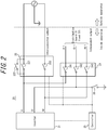
- FIG. 2 is a more detailed circuit configuration diagram related to the power control apparatus 20.
- the power grid is a 200 V single-phase three-wire system.
- the power control apparatus 20 includes two interconnection relays 221 and 222 (first and second interconnection relays) for interconnecting or paralleling off the inverter 21 to or from the power grid.
- the interconnection relays 221 and 222 are located inside the power control apparatus 20.
- the power control apparatus 20 includes an inrush current reduction relay (rush relay) 223 in parallel with the interconnection relay 221.
- the inrush current refers to a current, flowing at the start of the power supply, that is larger than the current that regularly flows.
- the rush relay 223 is for preventing the interconnection relay 221 from breaking due to inrush current generated at the start of interconnected operation.
- the power control apparatus 20 is illustrated as including the rush relay 223, but embodiments of the present disclosure are not limited to this configuration.
- the power control apparatus 20 need not include the rush relay 223.
- the power control apparatus 20 includes three independent operation relays 241, 242, and 243 for connecting the inverter 21 and the load 32 during independent operation.
- the voltage lines and neutral line for supplying electric power from the inverter 21 to the load 32 during independent operation branch off from between the inverter 21 and the interconnection relays 221 and 222.
- the independent operation relays 241, 242, and 243 are located between the branch point and the distribution board 31. In the example in FIG. 2 , the independent operation relays 241, 242, and 243 are located inside the power control apparatus 20.
- the power control apparatus 20 includes a reference potential relay 26 for setting the neutral phase (O-phase) of the independent operation output system to a reference potential.
- the reference potential relay 26 is provided in the O-phase.
- the reference potential is obtained by grounding the O-phase through the reference potential relay 26.
- the certification standard of an electricity storage system prescribes grounding of the O-phase of the independent operation output system. This requirement is satisfied by grounding the O-phase through the reference potential relay 26.
- the reference potential may be 0 V or a different value.
- the power control apparatus 20 includes interconnection relays 221 and 222 that have a mechanism for interconnecting to, or paralleling off from, the power grid during operation or when stopping.
- interconnection relays 221 and 222 that have a mechanism for interconnecting to, or paralleling off from, the power grid during operation or when stopping.
- a phenomenon in which the relay does not function normally may occur unintentionally, for reasons such as inrush current, vibration, or unintentional shock.
- the phenomenon may, for example, be welding.
- Welding is a phenomenon in which a power line inside the relay cannot be separated for the aforementioned reasons.
- the state could be detected by a method to confirm the voltage difference between the sides of the relay, but it has proven difficult to detect the state of an individual relay.
- a fault location can be identified, thereby preventing the amount of labor and costs from increasing at the time of maintenance or the like.
- using the present method can prevent an increase in costs.
- the present method can also prevent increased complexity as compared to when using a circuit system configured by combining these circuits for detecting the state.
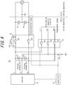
- FIG. 3 and FIG. 4 are more detailed circuit configuration diagrams related to the power control apparatus 20 during interconnected operation and at the start of interconnected operation.
- the power control apparatus 20 further includes voltage sensors 51 and 52 (first set of voltage sensors).
- the voltage sensor 51 is installed between the interconnection relay 221 and the inverter 21, and the voltage sensor 52 is installed between the interconnection relay 221 and the power grid.
- the power control apparatus 20 further includes voltage sensors 53 and 54 (second set of voltage sensors).
- the voltage sensor 53 is installed between the interconnection relay 222 and the inverter 21, and the voltage sensor 54 is installed between the interconnection relay 222 and the power grid.
- the installation of voltage sensors in the interconnected operation output system of the power control apparatus that interconnects with the power grid is prescribed.
- the voltage sensors 51 to 54 are conventionally installed in accordance with this prescription.
- the voltage sensors 51 and 52 are designated as the first set of voltage sensors, and the voltage sensors 53 and 54 as the second set of voltage sensors, but these designations are not limiting.
- the designations of the first and second sets of voltage sensors may be switched.
- the interconnection relays 221 and 222 and the rush relay 223 are used, whereas the independent operation relays 241 to 243 and the reference potential relay 26 normally remain off. In this way, the reference potential relay 26 remains off during interconnected operation, and the potential of the O-phase on the inverter 21 side is not determined.
- the voltage sensor 51 cannot measure the voltage between the U-phase and the O-phase, and the voltage sensor 53 cannot measure the voltage between the W-phase and the O-phase.
- the controller 25 newly performs control to turn the reference potential relay 26 on before the start of interconnected operation, as illustrated in FIG. 4 .
- the O-phase is grounded, and a reference potential (earth (E)) of 0 V is obtained.
- the voltage sensor 51 can measure the voltage between the U-phase and the O-phase (U-E) on the inverter 21 side.
- the voltage sensor 53 can measure the voltage between the W-phase and the O-phase (W-E) on the inverter 21 side.
- the O-phase is grounded from the start.
- the voltage sensor 52 can measure the voltage between the U-phase and the O-phase (U-E) on the power grid side.
- the voltage sensor 54 can measure the voltage between the W-phase and the O-phase (W-E) on the power grid side.
- the controller 25 judges whether the interconnection relay 221 is welded on the basis of the voltage values measured by the voltage sensors 51 and 52. If these voltage values are the same, the controller 25 judges that either the interconnection relay 221 or the rush relay 223 is not off as normal before the start of interconnected operation and is welded. Hence, the controller 25 outputs an error.
- the judgment of welding is not limited to the case of the voltage values being the same. The judgment of welding may be made when the difference between the voltage values measured by the voltage sensor 51 and the voltage sensor 52 is within a certain threshold range, such as ⁇ 5%. If the voltage values are different, the controller 25 judges that the interconnection relay 221 and the rush relay 223 are not welded. When the power control apparatus 20 does not include the rush relay 223, the controller 25 can judge the welding state for the interconnection relay 221 alone.
- the controller 25 judges whether the interconnection relay 222 is welded on the basis of the voltage values measured by the voltage sensors 53 and 54. If these voltage values are the same, the controller 25 judges that the interconnection relay 222 is not off as normal before the start of interconnected operation and is welded. Hence, the controller 25 outputs an error. If the voltage values are different, the controller 25 judges that the interconnection relay 222 is not welded.
- the power control apparatus can judge the welding state of each of the interconnection relays 221 and 222 at the start of interconnected operation by using only simple relays, without using expensive relays individually provided with a detection circuit having a welding detection function. In other words, the power control apparatus according to an embodiment of the present disclosure achieves inexpensive, simple, and individual detection of the welding state of the interconnection relays 221 and 222.
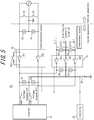
- FIG. 5 is a more detailed circuit configuration diagram related to the power control apparatus 20 during independent operation.
- the power control apparatus 20 may further include voltage sensors 55 and 56 (third set of voltage sensors).
- the voltage sensor 55 is installed between the independent operation relay 241 (first independent operation relay) and the inverter 21, and the voltage sensor 56 is installed between the independent operation relay 241 and the distribution board 31 (load 32).
- the power control apparatus 20 may further include voltage sensors 57 and 58 (fourth set of voltage sensors).
- the voltage sensor 57 is installed between the independent operation relay 243 (second independent operation relay) and the inverter 21, and the voltage sensor 58 is installed between the independent operation relay 243 and the distribution board 31 (load 32).
- the independent operation relay 241 is designated as the first independent operation relay
- the independent operation relay 243 is designated as the second independent operation relay, but the present disclosure is not limited to these designations.
- the voltage sensors 55 and 56 are designated as the third set of voltage sensors, and the voltage sensors 57 and 58 as the fourth set of voltage sensors, but the present disclosure is not limited to these designations. The designations of the third and fourth sets of voltage sensors may be switched.
- the independent operation relays 241 to 243 and the reference potential relay 26 are used, whereas the interconnection relays 221 and 222 and the rush relay 223 remain off. If the reference potential relay 26 also remains off, then as described above, the potential of the O-phase is not determined, and the voltage sensors 51, 53, and 55 to 58 cannot measure the corresponding voltage between the U-phase and the O-phase and the voltage between the W-phase and the O-phase.
- the controller 25 newly performs control to turn the reference potential relay 26 on before the start of independent operation as well, as illustrated in FIG. 5 .
- the O-phase is grounded, and a reference potential (earth (E)) of 0 V is obtained.
- the inverter 21 thus outputs a micro voltage before the start of independent operation.
- the micro voltage is AC voltage with an output time corresponding to 1 cycle or more of AC voltage.
- a micro voltage output for less than 1 cycle may lead to misdetection during welding detection.
- the reason for outputting micro voltage for 1 cycle or more may also be to increase detection accuracy.
- An excessively long output time is time consuming, however, and the micro voltage might not be distinguishable from electric power flowing during interconnected operation. Therefore, the output time can, for example, be set to 1 cycle or more and 10 cycles or less.
- the output time may, for example, be set to 2 cycles or more and 6 cycles or less.
- the voltage value of the micro voltage prefferably be set to a value sufficiently lower than AC 100 V.
- the micro voltage can, for example, be set to a value that is larger than AC 0 V and is AC 10 V or less.
- the micro voltage may be set to a value that is larger than AC 0 V and is AC 5 V or less.
- the voltage sensors 51 to 54 can measure the respective voltages. If the interconnection relays 221 and 222 and the rush relay 223 are not welded, i.e. if these relays are off as normal, then power is not supplied from the power grid, and the voltage values of the voltage sensors 52 and 54 become 0 V. On the other hand, if the interconnection relay 221 or the rush relay 223 is welded, the voltage value of the voltage sensor 52 becomes the same as the voltage value of the voltage sensor 51. Similarly, if the interconnection relay 222 is welded, the voltage value of the voltage sensor 54 becomes the same as the voltage value of the voltage sensor 53.
- the controller 25 judges whether the interconnection relay 221 is welded on the basis of the voltage values measured by the voltage sensors 51 and 52. If these voltage values are the same, the controller 25 judges that either the interconnection relay 221 or the rush relay 223 is not off as normal before the start of independent operation and is welded. Hence, the controller 25 outputs an error. If the voltage values are different, the controller 25 judges that the interconnection relay 221 and the rush relay 223 are not welded. When the power control apparatus 20 does not include the rush relay 223, the controller 25 can judge the welding state for the interconnection relay 221 alone.
- the controller 25 judges whether the interconnection relay 222 is welded on the basis of the voltage values measured by the voltage sensors 53 and 54. If these voltage values are the same, the controller 25 judges that the interconnection relay 222 is not off as normal before the start of independent operation and is welded. Hence, the controller 25 outputs an error. If the voltage values are different, the controller 25 judges that the interconnection relay 222 is not welded.
- the controller 25 judges the welding state of the independent operation relays 241 to 243 is described.
- the inverter 21 outputs a micro voltage before the start of independent operation, because power from the power grid is not supplied during independent operation.
- the voltage sensors 55 to 58 can measure the respective voltages. If the independent operation relays 241 to 243 are not welded, i.e. if these relays are off as normal before the start of independent operation, then the voltage values of the voltage sensors 56 and 58 become 0 V. On the other hand, if the independent operation relay 241 or 242 is welded, the voltage value of the voltage sensor 56 becomes the same as the voltage value of the voltage sensor 55. Similarly, if the independent operation relay 242 or 243 is welded, the voltage value of the voltage sensor 58 becomes the same as the voltage value of the voltage sensor 57.
- the controller 25 judges whether the independent operation relay 241 or 242 is welded on the basis of the voltage values measured by the voltage sensors 55 and 56. If these voltage values are the same, the controller 25 judges that the independent operation relay 241 or 242 is not off as normal before the start of independent operation and is welded. Hence, the controller 25 outputs an error. If the voltage values are different, the controller 25 judges that the independent operation relays 241 and 242 are not welded.
- the controller 25 judges whether the independent operation relay 242 or 243 is welded on the basis of the voltage values measured by the voltage sensors 57 and 58. If these voltage values are the same, the controller 25 judges that the independent operation relay 242 or 243 is not off as normal before the start of independent operation and is welded. Hence, the controller 25 outputs an error. If the voltage values are different, the controller 25 judges that the independent operation relays 242 and 243 are not welded.
- the controller 25 can judge that none of the independent operation relays 241 to 243 is welded. If the voltage values of the third set of voltage sensors differ but the voltage values of the fourth set of voltage sensors are the same, then the controller 25 can judge that only the independent operation relay 243 is welded. If the voltage values of the third set of voltage sensors are the same but the voltage values of the fourth set of voltage sensors differ, then the controller 25 can judge that only the independent operation relay 241 is welded.
- the power control apparatus can thus judge the welding state of relays inside the power control apparatus 20 even at the start of independent operation by using only simple relays, without using expensive relays individually provided with a detection circuit having a welding detection function.
- the power control apparatus achieves inexpensive, simple, and individual detection of the welding state of the interconnection relays 221 and 222 inside the power control apparatus 20.
- the operations of the power control apparatus differ between the start of interconnected operation and the start of independent operation.
- the controller 25 confirms whether power is being supplied from the power grid (step S100). When power is being supplied from the power grid, the process proceeds to step S101. When power is not being supplied from the power grid, the process proceeds to step S200 in FIG. 6B . First, the operations at the start of interconnected operation are described with reference to FIG. 6A .
- the controller 25 turns the reference potential relay 26 on (step S101). In this way, the O-phase is grounded, and a reference potential of 0 V is obtained.
- step S102 the controller 25 compares the voltage values measured by the voltage sensors 51 and 52 (step S102). If the voltage values are the same, the process proceeds to step S103. If the voltage values are different, the process proceeds to step S104.
- the controller 25 judges that the interconnection relay 221 or the rush relay 223 is welded and outputs an error (step S103).
- step S104 the controller 25 judges that the interconnection relay 221 and the rush relay 223 are not welded and then compares the voltage values measured by the voltage sensors 53 and 54 (step S104). If the voltage values are the same, the process proceeds to step S105. If the voltage values are different, the process proceeds to step S106.
- the controller 25 judges that the interconnection relay 222 is welded and outputs an error (step S105).
- the controller 25 keeps the interconnection relay 222 and the rush relay 223 on, because by the above operations, the controller 25 has detected that the interconnection relays 221 and 222 and the rush relay 223 are not welded (step S106).
- the controller 25 turns the interconnection relay 221 on (step S107).
- the controller 25 then turns the rush relay 223 off (step S108).
- interconnected operation starts (step S109).
- the controller 25 switches to independent operation mode (step S200).
- the controller 25 turns the reference potential relay 26 on (step S201). In this way, the O-phase is grounded, and a reference potential of 0 V is obtained.
- the inverter 21 outputs AC voltage (step S202).
- the output time of the AC voltage may be 2 cycles or more and 6 cycles or less of the AC voltage.
- step S203 the controller 25 compares the voltage values measured by the voltage sensors 51 and 52 (step S203). If the voltage values are the same, the process proceeds to step S204. If the voltage values are different, the process proceeds to step S206.
- step S204 the controller 25 reconfirms whether power is being supplied from the power grid. This is to confirm whether power has been restored unintentionally at the start of independent operation.
- step S100 the process returns to step S100.
- step S205 the process proceeds to step S205.
- the controller 25 judges that the interconnection relay 221 or the rush relay 223 is welded and outputs an error (step S205).
- step S206 the controller 25 judges that the interconnection relay 221 and the rush relay 223 are not welded and then compares the voltage values measured by the voltage sensors 53 and 54 (step S206). If the voltage values are the same, the process proceeds to step S207. If the voltage values are different, the process proceeds to step S209.
- step S207 the controller 25 reconfirms whether power is being supplied from the power grid. This is to confirm whether power has been restored unintentionally at the start of independent operation.
- step S100 the process returns to step S100.
- step S208 the process proceeds to step S208.
- step S208 the controller 25 judges that the interconnection relay 222 is welded and outputs an error.
- step S209 the controller 25 judges that the interconnection relay 222 is not welded and then compares the voltage values measured by the voltage sensors 55 and 56 (step S209). If the voltage values are the same, the process proceeds to step S210. If the voltage values are different, the process proceeds to step S212.
- step S210 the controller 25 reconfirms whether power is being supplied from the power grid. This is to confirm whether power has been restored unintentionally at the start of independent operation.
- step S100 the process returns to step S100.
- step S211 the process proceeds to step S211.
- the controller 25 judges that the independent operation relay 241 or 242 is welded and outputs an error (step S211).
- step S212 the controller 25 judges that the independent operation relays 241 and 242 are not welded and then compares the voltage values measured by the voltage sensors 57 and 58 (step S212). If the voltage values are the same, the process proceeds to step S213. If the voltage values are different, the process proceeds to step S215.
- step S213 the controller 25 reconfirms whether power is being supplied from the power grid. This is to confirm whether power has been restored unintentionally at the start of independent operation.
- step S100 the process returns to step S100.
- step S214 the process proceeds to step S214.
- the controller 25 judges that the independent operation relay 242 or 243 is welded and outputs an error (step S214).
- the controller 25 judges that the independent operation relays 242 and 243 are not welded and reconfirms whether power is being supplied from the power grid (step S215). When power is being supplied from the power grid and has been restored unintentionally, the process returns to step S100. When power is not being supplied from the power grid, the process proceeds to step S216.
- the controller 25 turns the independent operation relays 241, 242, and 243 on, because by the above operations, the controller 25 has detected that the interconnection relays 221 and 222, the rush relay 223, and the independent operation relays 241, 242, and 243 are not welded (step S216).
- the power control apparatus can thus judge the welding state of relays inside the power control apparatus 20 at the start of interconnected operation and at the start of independent operation by using simple relays, without using expensive relays individually provided with a detection circuit having a welding detection function.
- the power control apparatus achieves inexpensive, simple, and individual detection of the welding state of the interconnection relays 221 and 222 inside the power control apparatus 20.
- a second embodiment is described next. A description of the second embodiment is omitted as appropriate for points identical to the first embodiment.
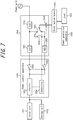
- FIG. 7 is a block diagram of the schematic configuration of the power control system according to an embodiment.
- the power control system according to the present embodiment includes a solar cell 1011, a storage cell 1012, a power control apparatus 1020, a distribution board 1031, a load 1032, a power generation apparatus 1033, a current sensor 1040, and a distribution board 1050.
- the functions of the solar cell 1011 and the storage cell 1012 are the same as those of the solar cell 11 and the storage cell 12 in the first embodiment, a description thereof is omitted.
- the power control apparatus 1020 converts DC power supplied from the solar cell 1011 and the storage cell 1012 and AC power supplied from the power grid and the power generation apparatus 1033 and also controls the switching between interconnected operation and independent operation.
- the power control apparatus 1020 includes an inverter 1021, an interconnection relay 1022, an independent operation relay 1023, and a controller 1024 that controls the power control apparatus 1020 overall.
- the inverter 1021 is a bidirectional inverter that converts DC power supplied from the solar cell 1011 and the storage cell 1012 into AC power and converts AC power supplied from the power grid and the power generation apparatus 1033 into DC power.
- a converter for stepping up the DC power from the solar cell 1011 and the storage cell 1012 to a predetermined voltage may be provided at a stage preceding the inverter 1021.
- the interconnection relay 1022 and the independent operation relay 1023 are each configured by a relay, transistor, or the like and are controlled to be on or off. As illustrated in the drawing, the independent operation relay 1023 is located between the power generation apparatus 1033 and the storage cell 1012. The interconnection relay 1022 and the independent operation relay 1023 are switched synchronously so as not to be on (or off) simultaneously. In greater detail, when the interconnection relay 1022 is turned on, the independent operation relay 1023 is turned off synchronously, and the power control apparatus 1020 performs interconnected operation. When the interconnection relay 1022 is turned off, the independent operation relay 1023 is turned on synchronously, and the power control apparatus 1020 performs independent operation.
- the synchronous control of the interconnection relay 1022 and the independent operation relay 1023 is implemented by hardware by branching the control signal wiring for the interconnection relay 1022 to the independent operation relay 1023.
- the on/off state in response to the same control signal may be set independently for each relay.
- the synchronous control of the interconnection relay 1022 and the independent operation relay 1023 may also be implemented by the controller 1024 via software.
- the controller 1024 is, for example, a microcomputer and controls the operations of the inverter 1021, the interconnection relay 1022, the independent operation relay 1023, and the like on the basis of the state of a power grid voltage increase, a power outage, and the like.
- the controller 1024 turns the interconnection relay 1022 on and turns the independent operation relay 1023 off.
- the controller 1024 turns the interconnection relay 1022 off and turns the independent operation relay 1023 on.
- the functions of the distribution board 1031, power generation apparatus 1033, and current sensor 1040 are the same as those of the distribution board 31, power generation apparatus 33, and current sensor 40 in the first embodiment respectively, a description thereof is omitted.
- the distribution board 1050 includes earth leakage breakers (ELB) 1051 and 1052, a miniature circuit breaker (MCB) 1053, and two relays (power grid bypass relay 1054 and changeover switch 1055).
- the ELBs 1051 and 1052 operate when earth leakage occurs. In other words, the ELBs 1051 and 1052 automatically shut off the flow of electric power when electrical wiring or an electrical appliance leaks electricity.
- the MCB 1053 is a small breaker for a consumer facility.
- the power grid bypass relay 1054 is electrically controlled to be on or off in accordance with the presence of power grid voltage. Specifically, the power grid bypass relay 1054 turns on when power grid voltage is present and turns off when power grid voltage is absent.
- the changeover switch 1055 is a relay that is manually switched on or off. If the power control apparatus 1020 were to malfunction and the distribution board 1050 only included the power grid bypass relay 1054, power could no longer be supplied from the power grid to the load 1032. If the changeover switch 1055 is further included, however, and an operator switches the changeover switch 1055 manually, the distribution board 1050 can supply power from the power grid even during the aforementioned malfunction.
- the power control system according to an embodiment is described in detail below.
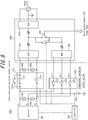
- FIG. 8 is a more detailed circuit configuration diagram related to the power control apparatus 1020 and the distribution board 1050.
- the power grid is a 200 V single-phase three-wire system.
- the power control apparatus 1020 includes two interconnection relays 1221 and 1222 (first and second interconnection relays) for interconnecting or paralleling off the inverter 1021 to or from the power grid.
- the interconnection relays 1221 and 1222 are located inside the power control apparatus 1020.
- the power control apparatus 1020 includes a rush relay 1223 in parallel with the interconnection relay 1221.
- the inrush current refers to a current, flowing at the start of the power supply, that is larger than the current that regularly flows.
- the rush relay 1223 is for preventing the inverter 1021 from breaking due to inrush current generated at the start of interconnected operation.
- the power control apparatus 1020 is illustrated as including the rush relay 1223, but embodiments are not limited to this configuration.
- the power control apparatus 1020 need not include the rush relay 1223.
- the power control apparatus 1020 includes three independent operation relays 1231, 1232, and 1233 for connecting the inverter 1021 and the load 1032 during independent operation.
- the voltage lines and neutral line for supplying electric power from the inverter 1021 to the load 1032 during independent operation branch off from between the inverter 1021 and the interconnection relays 1221 and 1222.
- the independent operation relays 1231, 1232, and 1233 are located between the branch point and the distribution board 1050. In the example in FIG. 8 , the independent operation relays 1231, 1232, and 1233 are located inside the power control apparatus 1020.
- the independent operation relay 1231 is designated as the first independent operation relay
- the independent operation relay 1233 is designated as the second independent operation relay, but these designations are not limiting.
- the power control apparatus 1020 includes a reference potential relay 1025 for setting the neutral phase (O-phase) of the independent operation output system to a reference potential.
- the reference potential relay 1025 is provided in the O-phase.
- the reference potential is obtained by grounding the O-phase through the reference potential relay 1025.
- the certification standard of an electricity storage system prescribes grounding of either one of the phases in the case of a single-phase two-wire system and grounding of any one of the phases of an independent operation output system in the case of three-wire connection. This requirement is satisfied by grounding the O-phase through the reference potential relay 1025.
- the reference potential may be 0 V or a different value.
- the power control apparatus 1020 further includes voltage sensors 1061 and 1062 (first set of voltage sensors).
- the voltage sensor 1061 is installed between the interconnection relay 1221 and the inverter 1021, and the voltage sensor 1062 is installed between the interconnection relay 1221 and the power grid.
- the power control apparatus 1020 further includes voltage sensors 1063 and 1064 (second set of voltage sensors).
- the voltage sensor 1063 is installed between the interconnection relay 1222 and the inverter 1021, and the voltage sensor 1064 is installed between the interconnection relay 1222 and the power grid.
- the installation of voltage sensors in the interconnected operation output system of the power control system that interconnects with the power grid is prescribed.
- the voltage sensors 1061 to 1064 are conventionally installed in accordance with this prescription.
- the voltage sensors 1061 and 1062 are designated as the first set of voltage sensors, and the voltage sensors 1063 and 1064 as the second set of voltage sensors, but these designations are not limiting.
- the designations of the first and second sets of voltage sensors may be switched.
- the power grid bypass relay 1054 is located between the independent operation output system and the interconnected operation output system.
- the power grid bypass relay 1054 is located inside the distribution board 1050, but this configuration is not limiting.
- the power grid bypass relay 1054 may be located inside the power control apparatus 1020.
- the wiring inside the distribution board 1050 is a single-phase three-wire system. In other words, the U-phase, O-phase, and W-phase of the ELB 1051 are connected to the U-phase, O-phase, and W-phase of the ELB 1052 respectively.
- the U1-phase, O1-phase, and W1-phase of the MCB 1053 are connected to the U-phase, O-phase, and W-phase of the ELBs 1051 and 1052, respectively, through the power grid bypass relay 1054.
- the wires in the single-phase three-wire system are indicated by three diagonal lines for the sake of simplicity.
- the power control apparatus 1020 has independent operation relays 1231, 1232, and 1233 for supplying power from the power generation system, such as the solar cell 1011 and the storage cell 1012, to the load 1032 during independent operation.
- a typical relay sometimes does not operate when desired for a physical or electrical reason, such as inrush current, vibration, or unintentional shock.
- the reason why the relay does not operate may, for example, be a phenomenon in which a contact made of a metal material is welded or may be an unintended problem in the circuit that operates the relay. Welding is a phenomenon in which a power line inside the relay cannot be separated for the aforementioned reasons.
- the power control system according to an embodiment is also simpler than using a circuit system configured by combining these circuits for detecting the welding state.
- FIG. 9 illustrates operations of each relay during interconnected operation. Focusing on the inside of the power control apparatus 1020, during interconnected operation, the interconnection relays 1221 and 1222 are used, whereas the rush relay 1223, the independent operation relays 1231 to 1233, and the reference potential relay 1025 normally remain off. On the other hand, focusing on the inside of the distribution board 1050, the power grid bypass relay 1054 is turned on because power grid voltage is present during interconnected operation. As illustrated in FIG. 8 , the changeover switch 1055 is connected to the terminal on the independent operation output system side.
- electric power flows in the direction indicated by the three arrows in FIG. 9 .
- electric power generated by the solar cell 1011 flows in reverse through the interconnection relays 1221 and 1222 to the power grid by the sale of power.
- electric power is supplied from the power grid to the load 1032 by the purchase of power.
- electric power is supplied from the power grid to the storage cell 1012 to charge the storage cell 1012.
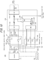
- FIG. 10 illustrates operations of each relay during independent operation. Focusing on the inside of the power control apparatus 1020, during independent operation, the independent operation relays 1231, 1232, and 1233 and the reference potential relay 1025 are used, whereas the interconnection relays 1221 and 1222 and the rush relay 1223 normally remain off. On the other hand, focusing on the inside of the distribution board 1050, the power grid bypass relay 1054 is off because power grid voltage is not present during independent operation. As illustrated in FIG. 10 , the changeover switch 1055 remains connected to the terminal on the independent operation output system side.
- FIG. 11 illustrates operations when detecting welding of the independent operation relays 1231, 1232, and 1233 after switching to interconnected operation.
- the reference potential relay 1025 remains off. Consequently, the potential of the O-phase on the inverter 1021 side is not determined.
- the voltage sensor 1061 cannot measure the voltage between the U-phase and the O-phase, and the voltage sensor 1063 cannot measure the voltage between the W-phase and the O-phase.
- the controller 1024 newly performs control to turn the reference potential relay 1025 on before the start of interconnected operation, as illustrated in FIG. 11 .
- the O-phase is grounded, and a reference potential (earth (E)) of 0 V is obtained.
- the voltage sensor 1061 can measure the voltage between the U-phase and the O-phase (U-E) on the inverter 1021 side, and the voltage sensor 1063 can measure the voltage between the W-phase and the O-phase (W-E) on the inverter 1021 side.
- the O-phase is grounded from the start.
- the voltage sensor 1062 can measure the voltage between the U-phase and the O-phase (U-E) on the power grid side
- the voltage sensor 1064 can measure the voltage between the W-phase and the O-phase (W-E) on the power grid side.
- the power grid bypass relay 1054 is on during interconnected operation.
- the interconnected operation output system and the independent operation output system are at the same potential.
- the voltage A of the interconnected operation output system becomes the same as the voltage A' of the independent operation output system, as illustrated in FIG. 11 . Consequently, the voltage between the U1-phase and the O1-phase (U1-E) of the independent operation output system can be measured by the voltage sensor 1062.
- the voltage B of the interconnected operation output system becomes the same as the voltage B' of the independent operation output system. Consequently, the voltage between the W1-phase and the O1-phase (W1-E) of the independent operation output system can be measured by the voltage sensor 1064.
- the controller 1024 judges whether each relay is welded on the basis of the voltage values measured by the voltage sensors 1061 and 1062. If the values are the same, the controller 1024 judges that at least one of the interconnection relay 1221, rush relay 1223, or independent operation relays 1231 and 1232 is not off as normal before the start of interconnected operation and is welded. Hence, the controller 1024 outputs an error.
- the values are not limited to being equal. It suffices for the difference between the voltage values measured by the voltage sensor 1061 and the voltage sensor 1062 to be within a certain threshold range, such as ⁇ 5%. If the values are different, the controller 1024 judges that none of the interconnection relay 1221, rush relay 1223, and independent operation relays 1231 and 1232 is welded.
- the controller 1024 judges whether each relay is welded on the basis of the voltage values measured by the voltage sensors 1063 and 1064. If the values are the same, the controller 1024 judges that at least one of the interconnection relay 1222 or independent operation relays 1232 and 1233 is not off as normal before the start of interconnected operation and is welded. Hence, the controller 1024 outputs an error. If the values are different, the controller 1024 judges that none of the interconnection relay 1222 and independent operation relays 1232 and 1233 is welded.
- the power control system can judge the welding state of the independent operation relays 1231, 1232, and 1233 at the start of interconnected operation by using only simple relays, without using expensive relays individually provided with a detection circuit having a welding detection function.
- the power control system according to an embodiment achieves inexpensive and simple detection of the welding state of not only the interconnection relays 1221 and 1222 but also the independent operation relays 1231, 1232, and 1233.
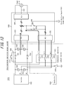
- FIG. 12 illustrates operations when detecting welding of the independent operation relays 1231, 1232, and 1233 after switching to independent operation.
- the reference potential relay 1025 is on. Consequently, the O-phase is grounded, and a reference potential (earth (E)) of 0 V is obtained.
- the voltage sensor 1061 can measure the voltage between the U-phase and the O-phase
- the voltage sensor 1063 can measure the voltage between the W-phase and the O-phase.
- the power grid bypass relay 1054 is off during independent operation. Accordingly, the controller 1024 performs control to turn the power grid bypass relay 1054 on once before the start of independent operation.
- the interconnected operation output system and the independent operation output system are at the same potential.
- the voltage A of the interconnected operation output system becomes the same as the voltage A' of the independent operation output system, as illustrated in FIG. 12 . Consequently, the voltage between the U1-phase and the O1-phase (U1-E) of the independent operation output system can be measured by the voltage sensor 1062.
- the voltage B of the interconnected operation output system becomes the same as the voltage B' of the independent operation output system. Consequently, the voltage between the W1-phase and the O1-phase (W1-E) of the independent operation output system can be measured by the voltage sensor 1064.
- the inverter 1021 outputs a micro voltage before the start of independent operation, because power from the power grid is not supplied during independent operation, unlike during interconnected operation.
- the micro voltage is AC voltage with an output time corresponding to 1 cycle or more of the AC voltage.
- a micro voltage output for less than 1 cycle may lead to misdetection during welding detection.
- the reason for outputting micro voltage for 1 cycle or more may also be to increase detection accuracy.
- An excessively long output time is time consuming, however, and the micro voltage might not be distinguishable from electric power flowing during interconnected operation. Therefore, the output time can, for example, be set to 1 cycle or more and 10 cycles or less.
- the output time may, for example, be set to 2 cycles or more and 6 cycles or less.
- the voltage value of the micro voltage prefferably be set to a value sufficiently lower than AC 100 V.
- the micro voltage can, for example, be set to a value that is larger than AC 0 V and is AC 10 V or less.
- the micro voltage may be set to a value that is larger than AC 0 V and is AC 5 V or less.
- the voltage sensors 1061 to 1064 can measure the respective voltages. If the interconnection relays 1221 and 1222, the rush relay 1223, and the independent operation relays 1231, 1232, and 1233 are not welded, i.e. if these relays are off as normal, then power is not supplied from the power grid. The voltage values of the voltage sensors 1062 and 1064 therefore become 0 V. On the other hand, if at least one of the interconnection relay 1221, the rush relay 1223, or the independent operation relays 1231 and 1232 is welded, the voltage value of the voltage sensor 1062 becomes the same as the voltage value of the voltage sensor 1061. Similarly, if at least one of the interconnection relay 1222 or the independent operation relays 1232 and 1233 is welded, the voltage value of the voltage sensor 1064 becomes the same as the voltage value of the voltage sensor 1063.
- the controller 1024 judges whether each relay is welded on the basis of the voltage values measured by the voltage sensors 1061 and 1062. If the values are the same, the controller 1024 judges that at least one of the interconnection relay 1221, rush relay 1223, or independent operation relays 1231 and 1232 is not off as normal before the start of independent operation and is welded. Hence, the controller 1024 outputs an error. If the values are different, the controller 1024 judges that none of the interconnection relay 1221, rush relay 1223, and independent operation relays 1231 and 1232 is welded.
- the controller 1024 judges whether each relay is welded on the basis of the voltage values measured by the voltage sensors 1063 and 1064. If the values are the same, the controller 1024 judges that at least one of the interconnection relay 1222 or independent operation relays 1232 and 1233 is not off as normal before the start of independent operation and is welded. Hence, the controller 1024 outputs an error. If the values are different, the controller 1024 judges that none of the interconnection relay 1222 and independent operation relays 1232 and 1233 is welded.
- the power control system can judge the welding state of the independent operation relays 1231, 1232, and 1233 even at the start of independent operation by using only simple relays, without using expensive relays individually provided with a detection circuit having a welding detection function.
- the power control system according to an embodiment achieves inexpensive and simple detection of the welding state of not only the interconnection relays 1221 and 1222 but also the independent operation relays 1231, 1232, and 1233.
- FIG. 13 illustrates the case of an independent operation relay being welded during interconnected operation.
- the independent operation relay 1231 is welded, for example, unlike the normal relay operation during interconnected operation illustrated in FIG. 9 .
- the output from the inverter 1021 is assumed to flow to the power grid through the interconnection relays 1221 and 1222. In the aforementioned case, however, output from the inverter 1021 also ends up flowing to the independent operation output system unintentionally.
- electric power passing through different paths collides inside the distribution board 1050, as illustrated in FIG. 13 . It is assumed that when electric power collides, an excessive voltage is applied to electrical circuits such as capacitors, causing the electrical circuits to burn out. It is also assumed that unintended reverse power flow will occur.
- each relay including the independent operation relays 1231, 1232, and 1233
- welding of each relay is detected before the start of interconnected operation, as described above.
- the controller 1024 judges that one of the relays is welded and outputs an error
- the controller 1024 stops operation of the inverter 1021. In this way, the occurrence of an unintended phenomenon when one of the independent operation relays 1231, 1232, and 1233 is welded can be reduced, improving the safety before the start of interconnected operation.
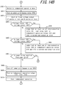
- the controller 1024 confirms whether power is being supplied from the power grid (step S300). When power is being supplied from the power grid, the process proceeds to step S301. When power is not being supplied from the power grid, the process proceeds to step S400 in FIG. 14B . First, the operations at the start of interconnected operation are described with reference to FIG. 14A .
- the controller 1024 turns the reference potential relay 1025 on (step S301). In this way, the O-phase is grounded, and a reference potential of 0 V is obtained.
- step S302 compares the voltage values measured by the voltage sensors 1061 and 1062 (step S302). If the voltage values are the same, the process proceeds to step S303. If the voltage values are different, the process proceeds to step S304.
- the controller 1024 judges that at least one of the interconnection relay 1221, rush relay 1223, or independent operation relays 1231 and 1232 is welded, outputs an error, and stops the inverter 1021 (step S303).
- the controller 1024 judges that none of the interconnection relay 1221, rush relay 1223, and independent operation relays 1231 and 1232 is welded. The controller 1024 then compares the voltage values measured by the voltage sensors 1063 and 1064 (step S304). If the voltage values are the same, the process proceeds to step S305. If the voltage values are different, the process proceeds to step S306.
- the controller 1024 judges that at least one of the interconnection relay 1222 or independent operation relays 1232 and 1233 is welded, outputs an error, and stops the inverter 1021 (step S305).
- the controller 1024 detects that none of the interconnection relays 1221 and 1222, rush relay 1223, and independent operation relays 1231, 1232, and 1233 is welded. The controller 1024 then turns the reference potential relay 1025 off (step S306).
- controller 1024 turns the interconnection relay 1222 and the rush relay 1223 on (step S307).
- the controller 1024 turns the interconnection relay 1221 on (step S308).
- the controller 1024 then turns the rush relay 1223 off (step S309).
- interconnected operation starts (step S310).
- step S400 When power is not being supplied from the power grid, the controller 1024 switches to independent operation mode (step S400). At this time, the controller 1024 turns the reference potential relay 1025 on. In this way, the O-phase is grounded, and a reference potential of 0 V is obtained.
- the controller 1024 turns the power grid bypass relay 1054 on (step S401).
- the interconnected operation output system and the independent operation output system are at the same potential.
- the inverter 1021 outputs AC voltage (step S402).
- the output time may be 2 cycles or more and 6 cycles or less of the AC voltage.
- step S403 the controller 1024 compares the voltage values measured by the voltage sensors 1061 and 1062 (step S403). If the voltage values are the same, the process proceeds to step S404. If the voltage values are different, the process proceeds to step S405.
- the controller 1024 judges that at least one of the interconnection relay 1221, rush relay 1223, or independent operation relays 1231 and 1232 is welded and outputs an error (step S404).
- step S405 If the voltage values are different, the controller 1024 judges that none of the interconnection relay 1221, rush relay 1223, and independent operation relays 1231 and 1232 is welded and then compares the voltage values measured by the voltage sensors 1063 and 1064 (step S405). If the voltage values are the same, the process proceeds to step S406. If the voltage values are different, the process proceeds to step S407.
- the controller 1024 judges that at least one of the interconnection relay 1222 or independent operation relays 1232 and 1233 is welded and outputs an error (step S406).
- the controller 1024 detects that none of the interconnection relays 1221 and 1222, rush relay 1223, and independent operation relays 1231, 1232, and 1233 is welded.
- the controller 1024 also reconfirms whether power is being supplied from the power grid (step S407). This is to confirm whether power has been restored unintentionally at the start of independent operation.
- the process returns to step S300.
- the process proceeds to step S408.
- controller 1024 turns the power grid bypass relay 1054 off (step S408).
- the controller 1024 also turns the independent operation relays 1231, 1232, and 1233 on (step S409).
- step S410 independent operation starts (step S410).
- the power control system according to an embodiment with the above configuration can thus judge the welding state of relays inside the power control apparatus 1020 at the start of interconnected operation and at the start of independent operation without using expensive relays individually provided with a detection circuit having a welding detection function.
- the power control system according to an embodiment thus achieves inexpensive and simple detection of the welding state of the independent operation relays 1231, 1232, and 1233 inside the power control apparatus 1020.
- the power grid bypass relay 1054, the changeover switch 1055, and the like have been described above as being located in the distribution board 1050, but this configuration is not limiting. Specifically, the power grid bypass relay 1054, the changeover switch 1055, and the like may be located inside the power control apparatus 1020. In this case, all of the components of the distribution board 1050 may be located within the power control apparatus 1020. In addition to the power grid bypass relay 1054 and the changeover switch 1055, at least one of the ELB 1051, the ELB 1052, or the MCB 1053 may be located within the power control apparatus 1020.
Description
- The present application claims priority to and the benefit of
Japanese Patent Application No. 2015-212401 filed October 28, 2015 Japanese Patent Application No. 2015-252264 filed December 24, 2015 - The present disclosure relates to a power control apparatus, a control method for a power control apparatus, a power control system, and a control method for a power control system.
- Prior art which is related to this technical field can be found in
JP 2014 064415 A - A known power control apparatus for a power generation system provided with power generation equipment, such as a solar panel, is capable of grid interconnected operation and independent operation. During grid interconnected operation, alternating current (AC) power is output while the power generation system is interconnected to a commercial power grid (hereinafter also "power grid"). During independent operation, AC power is output while the power generation system is paralleled off from the power grid.
- Like the aforementioned power control apparatus, a known electricity storage power control apparatus for an electricity storage system provided with electricity storage equipment such as a storage cell that is charged by power from the power grid is capable of grid interconnected operation and independent operation.
- The present disclosure provides a power control apparatus according to
claim 1. - The present disclosure provides a control method according to claim 8.
- The present disclosure provides a power control system according to claim 9.
- The present disclosure provides a control method according to claim 15.
- In the accompanying drawings:
-
FIG. 1 is a block diagram of a power control system including a power control apparatus according to a first embodiment; -
FIG. 2 is a more detailed circuit configuration diagram of the power control apparatus according to the first embodiment; -
FIG. 3 is a more detailed circuit configuration diagram during interconnected operation of the power control apparatus according to the first embodiment; -
FIG. 4 is a more detailed circuit configuration diagram at the start of interconnected operation of the power control apparatus according to the first embodiment; -
FIG. 5 is a more detailed circuit configuration diagram during independent operation of the power control apparatus according to the first embodiment; -
FIG. 6A is a flowchart illustrating operations at the start of interconnected operation of the power control apparatus according to the first embodiment; -
FIG. 6B is a flowchart illustrating operations at the start of independent operation of the power control apparatus according to the first embodiment; -
FIG. 7 is a block diagram of the schematic configuration of a power control system according to a second embodiment; -
FIG. 8 is a more detailed circuit configuration diagram of the power control system according to the second embodiment; -
FIG. 9 illustrates operations of each relay during interconnected operation; -
FIG. 10 illustrates operations of each relay during independent operation; -
FIG. 11 illustrates operations when detecting welding of the independent operation relays after switching to interconnected operation; -
FIG. 12 illustrates operations when detecting welding of the independent operation relays after switching to independent operation; -
FIG. 13 illustrates the case of an independent operation relay being welded during interconnected operation; -
FIG. 14A is a flowchart illustrating operations at the start of interconnected operation of the power control system according to the second embodiment; and -
FIG. 14B is a flowchart illustrating operations at the start of independent operation of the power control system according to the second embodiment. - To connect to the power grid, a mechanism (such as a relay) to interconnect to and parallel off from the power grid needs to be included. A phenomenon in which the relay does not function normally may occur unintentionally. The phenomenon may, for example, be welding. The state of the relay needs to be detected to determine whether this phenomenon has occurred. The power control apparatus, control method for a power control apparatus, power control system, and control method for a power control system of the present disclosure can detect the state of an interconnection relay.
- First, the overall power control system that includes the power control apparatus according to the first embodiment of the present disclosure is described. In addition to power supplied from the power grid, the power control system that includes the power control apparatus according to the present embodiment is provided with a distributed power source that supplies sellable power and/or a distributed power source that supplies power that cannot be sold by contract. A distributed power source that supplies sellable power is, for example, a system that supplies power by solar power generation or the like. The power grid referred to here is a system combining power generation, transformation, transmission, and distribution necessary for consumer facilities to receive electric power. For example, the power grid includes distribution equipment for consumer facilities to receive the power supply. By sending electric power to the power grid from a distributed power source that supplies sellable power, the surplus power after subtracting the power consumption within the consumer facility from the supplied power may be sold to the power company.
- On the other hand, a distributed power source that supplies electric power that cannot be sold by contract may, for example, be a storage cell system that can charge and discharge electric power, a fuel cell system that includes a fuel cell such as a solid oxide fuel cell (SOFC), and a gas power generator system that generates power with gas fuel. The present embodiment illustrates an example of including a solar cell as a distributed power source that supplies sellable power. The present embodiment also illustrates an example of including a storage cell and a power generation apparatus, which is a fuel cell or a gas power generator, as distributed power sources that supply power that cannot be sold by contract. The distributed power sources that are indicated as not being able to sell power by contract in the present embodiment may be able to sell power output by the distributed power sources as a result of changes in the system.
-
FIG. 1 is a block diagram illustrating the schematic configuration of a power control system including a power control apparatus according to a first embodiment of the present disclosure. The power control system includes asolar cell 11, astorage cell 12, apower control apparatus 20, adistribution board 31, aload 32, apower generation apparatus 33, and acurrent sensor 40. Thepower generation apparatus 33 is constituted by a fuel cell or a gas power generator. The power control system usually performs interconnected operation with the power grid. The power control system supplies power from the power grid and power from the distributed power sources (solar cell 11,storage cell 12, power generation apparatus 33) to theload 32. - When there is no power supply from the power grid, for example during a power outage, the power control system performs independent operation. The power control system supplies power from the distributed power sources (
solar cell 11,storage cell 12, power generation apparatus 33) to theload 32. When the power control system performs independent operation, the distributed power sources (solar cell 11,storage cell 12, power generation apparatus 33) are in a state of being paralleled off from the power grid. When the power control system performs interconnected operation, the distributed power sources (solar cell 11,storage cell 12, power generation apparatus 33) are in a state of being paralleled to the power grid. Here, the state of being paralleled off from the power grid refers to a state of being electrically disconnected from the power grid, and the state of paralleled to the power grid refers to a state of being electrically connected to the power grid. - The solid lines connecting functional blocks in
FIG. 1 represent wiring through which power flows. The dotted lines connecting functional blocks inFIG. 1 represent the flow of control signals or communicated information. The communication represented by the dotted lines may be wired communication or wireless communication. Various schemes may be adopted for communication of control signals and information, including each layer. For example, a short distance communication method such as ZigBee® (ZigBee is a registered trademark in Japan, other countries, or both) or the like may be used in communication of control signals and information. Various transmission media such as infrared communication and power line communication (PLC) may also be used in communication of control signals and information. Moreover, any of various communication protocols defining only the logical layer, such as ZigBee®, Smart Energy Profile 2.0 (SEP 2.0), ECHONET Lite® (ECHONET Lite is a registered trademark in Japan, other countries, or both), or KNX, may be operated on lower layers including the physical layer suitable for each communication. - The
solar cell 11 converts energy from sunlight into direct current (DC) electric power. For example, thesolar cell 11 is formed by connecting power generators having photoelectric conversion cells in a matrix to output a predetermined short-circuit current (e.g. 10 A). Thesolar cell 11 may be any type of solar cell capable of photoelectric conversion, such as a polycrystalline silicon solar cell, a monocrystalline silicon solar cell, or a CIGS or other thin-film solar cell. - The
storage cell 12 is a storage cell, such as a lead battery, a lithium ion battery, a nickel-metal-hydride battery, a NAS battery, or a redox flow battery. Thestorage cell 12 may be discharged to supply electric power. Thestorage cell 12 is chargeable not only with power supplied from the power grid or thesolar cell 11 but also with power supplied from thepower generation apparatus 33. - The
power control apparatus 20 converts DC power supplied from thesolar cell 11 and thestorage cell 12 and AC power supplied from the power grid and thepower generation apparatus 33 and also controls the switching between interconnected operation and independent operation. Thepower control apparatus 20 includes aninverter 21, interconnection relays 22 and 23, anindependent operation relay 24, and acontroller 25 that controls thepower control apparatus 20 overall. Theinterconnection relay 23 may be located outside thepower control apparatus 20. - The
inverter 21 is a bidirectional inverter. Theinverter 21 converts DC power supplied from thesolar cell 11 and thestorage cell 12 into AC power. Theinverter 21 also converts AC power supplied from the power grid and thepower generation apparatus 33 into DC power. A converter for stepping up the DC power from thesolar cell 11 and thestorage cell 12 to a predetermined voltage may be provided at a stage preceding theinverter 21. - The interconnection relays 22 and 23 and the
independent operation relay 24 are each configured by a relay, transistor, or the like and are controlled to be on or off. As illustrated in the drawing, theindependent operation relay 24 is located between thepower generation apparatus 33 and thestorage cell 12. The interconnection relays 22 and 23 and theindependent operation relay 24 are switched synchronously so as not to be on (or off) simultaneously. In greater detail, when the interconnection relays 22 and 23 are turned on, theindependent operation relay 24 is turned off synchronously, and thepower control apparatus 20 performs interconnected operation. When the interconnection relays 22 and 23 are turned off, theindependent operation relay 24 is turned on synchronously, and thepower control apparatus 20 performs independent operation. The synchronous control of the interconnection relays 22 and 23 and theindependent operation relay 24 is implemented by hardware by branching the control signal wiring for the interconnection relays 22 and 23 to theindependent operation relay 24. Here, the on/off state in response to the same control signal may be set independently for each relay. The synchronous control of the interconnection relays 22 and 23 and theindependent operation relay 24 may also be implemented by thecontroller 25 via software. - The
controller 25 is, for example, a microcomputer. Thecontroller 25 controls the operations of theinverter 21, the interconnection relays 22 and 23, theindependent operation relay 24, and the like on the basis of the state of a power grid voltage increase, a power outage, and the like. During interconnected operation, thecontroller 25 turns the interconnection relays 22 and 23 on and turns theindependent operation relay 24 off. During independent operation, thecontroller 25 turns the interconnection relays 22 and 23 off and turns theindependent operation relay 24 on. - The
distribution board 31 separates the electric power supplied by the power grid during interconnected operation into a plurality of branches and distributes the electric power to theload 32. Thedistribution board 31 separates the electric power supplied from the plurality of distributed power sources (solar cell 11,storage cell 12, power generation apparatus 33) into a plurality of branches and distributes the electric power to theload 32. Theload 32 is an electric power load that consumes electric power. Examples of theload 32 include a variety of household electrical appliances such as an air conditioner, microwave oven, and television; machinery and lighting facilities, such as air conditioning equipment and lighting equipment, that are used in commercial and industrial facilities; and the like. - The
power generation apparatus 33 is constituted by a fuel cell or a gas power generator. The fuel cell includes a cell that generates DC power using hydrogen through a chemical reaction with oxygen in the air, an inverter that converts the generated DC power to 100 V or 200 V AC power, and other auxiliary equipment. The fuel cell serving as thepower generation apparatus 33 is a system that can supply AC power to theload 32 without involving thepower control apparatus 20 and is not necessarily designed based on the assumption of being connected to thepower control apparatus 20. The fuel cell may thus be a versatile system. The gas power generator generates power by a gas engine that uses a predetermined gas or the like as fuel. - The
power generation apparatus 33 generates power while the correspondingcurrent sensor 40 detects current flowing in a first direction. When generating power, thepower generation apparatus 33 performs a load-following operation to follow the power consumption of theload 32 or a rated operation at predetermined rated power. The current flowing in the first direction may, for example, be the current flowing in the direction in which the consumer facility buys power, i.e. forward power flow, but is not limited to forward power flow. The range of following during the load-following operation is, for example, 200 W to 700 W. The rated power during the rated operation is, for example, 700 W. Thepower generation apparatus 33 may perform a load-following operation to follow the power consumption of theload 32 during interconnected operation and may perform a load-following operation or a rated operation at rated power during independent operation. Here, buying power is the antonym of selling power and refers to the consumer facility purchasing electric power from the power company. - The
current sensor 40 detects the current flowing between the power grid and thepower generation apparatus 33. For example, when the electric power generated by thepower generation apparatus 33 is prescribed by contract as not being sellable, thepower generation apparatus 33 stops generating power when thecurrent sensor 40 detects current flowing in a second direction towards the power grid. The current flowing in the second direction may, for example, be the current flowing in the direction of selling power from the consumer facility to the power grid, i.e. reverse power flow, but is not limited to reverse power flow. While thecurrent sensor 40 detects forward power flow, thepower generation apparatus 33 generates power by a load-following operation or a rated operation on the grounds that thepower generation apparatus 33 can supply electric power itself to theload 32. The power control apparatus according to an embodiment of the present disclosure is described below in detail. -
FIG. 2 is a more detailed circuit configuration diagram related to thepower control apparatus 20. In the example inFIG. 2 , the power grid is a 200 V single-phase three-wire system. In greater detail, thepower control apparatus 20 includes twointerconnection relays 221 and 222 (first and second interconnection relays) for interconnecting or paralleling off theinverter 21 to or from the power grid. The interconnection relays 221 and 222 are located inside thepower control apparatus 20. To reduce the inrush current, thepower control apparatus 20 includes an inrush current reduction relay (rush relay) 223 in parallel with theinterconnection relay 221. Here, the inrush current refers to a current, flowing at the start of the power supply, that is larger than the current that regularly flows. - The
rush relay 223 is for preventing theinterconnection relay 221 from breaking due to inrush current generated at the start of interconnected operation. InFIG. 2 , thepower control apparatus 20 is illustrated as including therush relay 223, but embodiments of the present disclosure are not limited to this configuration. For example, thepower control apparatus 20 need not include therush relay 223. - The
power control apparatus 20 includes three independent operation relays 241, 242, and 243 for connecting theinverter 21 and theload 32 during independent operation. The voltage lines and neutral line for supplying electric power from theinverter 21 to theload 32 during independent operation branch off from between theinverter 21 and the interconnection relays 221 and 222. The independent operation relays 241, 242, and 243 are located between the branch point and thedistribution board 31. In the example inFIG. 2 , the independent operation relays 241, 242, and 243 are located inside thepower control apparatus 20. - The
power control apparatus 20 includes a referencepotential relay 26 for setting the neutral phase (O-phase) of the independent operation output system to a reference potential. The referencepotential relay 26 is provided in the O-phase. As one example, the reference potential is obtained by grounding the O-phase through the referencepotential relay 26. Here, the certification standard of an electricity storage system prescribes grounding of the O-phase of the independent operation output system. This requirement is satisfied by grounding the O-phase through the referencepotential relay 26. The reference potential may be 0 V or a different value. - As described above, the
power control apparatus 20 includes interconnection relays 221 and 222 that have a mechanism for interconnecting to, or paralleling off from, the power grid during operation or when stopping. In a typical relay, however, a phenomenon in which the relay does not function normally may occur unintentionally, for reasons such as inrush current, vibration, or unintentional shock. The phenomenon may, for example, be welding. Welding is a phenomenon in which a power line inside the relay cannot be separated for the aforementioned reasons. For example, it is assumed that if independent operation starts without the state of the interconnection relays 221 and 222 having been detected before independent operation, then the generated power, which is supposed to be unsellable, from thepower generation apparatus 33 may flow in reverse to the power grid. Accordingly, a power control apparatus for detecting the state of the interconnection relays 221 and 222 and a control method for the power control apparatus are necessary. - The state could be detected by a method to confirm the voltage difference between the sides of the relay, but it has proven difficult to detect the state of an individual relay. By detecting the state of an individual relay, a fault location can be identified, thereby preventing the amount of labor and costs from increasing at the time of maintenance or the like. On the other hand, as compared to when a detection circuit having a state detection function is provided inside an individual relay, for example when a peripheral circuit for detection, such as a control circuit, is further included, using the present method can prevent an increase in costs. The present method can also prevent increased complexity as compared to when using a circuit system configured by combining these circuits for detecting the state.
- An inexpensive and simple method for individually detecting the state of the interconnection relays 221 and 222 using the power control apparatus according to an embodiment of the present disclosure is described below. Here, a method for detecting the welding state of the interconnection relays 221 and 222 is described. After turning the reference
potential relay 26 on and setting the O-phase to the reference potential, the power control apparatus according to an embodiment of the present disclosure judges whether each of the interconnection relays 221 and 222 is welded on the basis of voltage values measured by the below-described sets of voltage sensors. First, the case of thepower control apparatus 20 starting interconnected operation with the power grid is described. -
FIG. 3 andFIG. 4 are more detailed circuit configuration diagrams related to thepower control apparatus 20 during interconnected operation and at the start of interconnected operation. Thepower control apparatus 20 further includesvoltage sensors 51 and 52 (first set of voltage sensors). Thevoltage sensor 51 is installed between theinterconnection relay 221 and theinverter 21, and thevoltage sensor 52 is installed between theinterconnection relay 221 and the power grid. Similarly, thepower control apparatus 20 further includesvoltage sensors 53 and 54 (second set of voltage sensors). Thevoltage sensor 53 is installed between theinterconnection relay 222 and theinverter 21, and thevoltage sensor 54 is installed between theinterconnection relay 222 and the power grid. The installation of voltage sensors in the interconnected operation output system of the power control apparatus that interconnects with the power grid is prescribed. Hence, thevoltage sensors 51 to 54 are conventionally installed in accordance with this prescription. InFIG. 3 , thevoltage sensors voltage sensors - During interconnected operation, the interconnection relays 221 and 222 and the
rush relay 223 are used, whereas the independent operation relays 241 to 243 and the referencepotential relay 26 normally remain off. In this way, the referencepotential relay 26 remains off during interconnected operation, and the potential of the O-phase on theinverter 21 side is not determined. Thevoltage sensor 51 cannot measure the voltage between the U-phase and the O-phase, and thevoltage sensor 53 cannot measure the voltage between the W-phase and the O-phase. - In the power control apparatus according to an embodiment of the present disclosure, the
controller 25 newly performs control to turn the referencepotential relay 26 on before the start of interconnected operation, as illustrated inFIG. 4 . In this way, the O-phase is grounded, and a reference potential (earth (E)) of 0 V is obtained. At this time, thevoltage sensor 51 can measure the voltage between the U-phase and the O-phase (U-E) on theinverter 21 side. Furthermore, thevoltage sensor 53 can measure the voltage between the W-phase and the O-phase (W-E) on theinverter 21 side. On the power grid side, the O-phase is grounded from the start. Hence, thevoltage sensor 52 can measure the voltage between the U-phase and the O-phase (U-E) on the power grid side. Furthermore, thevoltage sensor 54 can measure the voltage between the W-phase and the O-phase (W-E) on the power grid side. - Subsequently, the
controller 25 judges whether theinterconnection relay 221 is welded on the basis of the voltage values measured by thevoltage sensors controller 25 judges that either theinterconnection relay 221 or therush relay 223 is not off as normal before the start of interconnected operation and is welded. Hence, thecontroller 25 outputs an error. The judgment of welding is not limited to the case of the voltage values being the same. The judgment of welding may be made when the difference between the voltage values measured by thevoltage sensor 51 and thevoltage sensor 52 is within a certain threshold range, such as ±5%. If the voltage values are different, thecontroller 25 judges that theinterconnection relay 221 and therush relay 223 are not welded. When thepower control apparatus 20 does not include therush relay 223, thecontroller 25 can judge the welding state for theinterconnection relay 221 alone. - Similarly, the
controller 25 judges whether theinterconnection relay 222 is welded on the basis of the voltage values measured by thevoltage sensors controller 25 judges that theinterconnection relay 222 is not off as normal before the start of interconnected operation and is welded. Hence, thecontroller 25 outputs an error. If the voltage values are different, thecontroller 25 judges that theinterconnection relay 222 is not welded. - By performing the above control, the power control apparatus according to an embodiment of the present disclosure can judge the welding state of each of the interconnection relays 221 and 222 at the start of interconnected operation by using only simple relays, without using expensive relays individually provided with a detection circuit having a welding detection function. In other words, the power control apparatus according to an embodiment of the present disclosure achieves inexpensive, simple, and individual detection of the welding state of the interconnection relays 221 and 222.
- Next, the case of the
power control apparatus 20 starting independent operation is described.FIG. 5 is a more detailed circuit configuration diagram related to thepower control apparatus 20 during independent operation. Thepower control apparatus 20 may further includevoltage sensors 55 and 56 (third set of voltage sensors). Thevoltage sensor 55 is installed between the independent operation relay 241 (first independent operation relay) and theinverter 21, and thevoltage sensor 56 is installed between theindependent operation relay 241 and the distribution board 31 (load 32). Similarly, thepower control apparatus 20 may further includevoltage sensors 57 and 58 (fourth set of voltage sensors). Thevoltage sensor 57 is installed between the independent operation relay 243 (second independent operation relay) and theinverter 21, and thevoltage sensor 58 is installed between theindependent operation relay 243 and the distribution board 31 (load 32). Unlike thevoltage sensors 51 to 54, installation of voltage sensors in the independent operation output system of the power control apparatus that connects to theload 32 is not prescribed. Thevoltage sensors 55 to 58, however, may be installed in the independent operation output system to detect the welding state of the independent operation relays 241 to 243. InFIG. 5 , theindependent operation relay 241 is designated as the first independent operation relay, and theindependent operation relay 243 is designated as the second independent operation relay, but the present disclosure is not limited to these designations. Similarly, thevoltage sensors voltage sensors - During independent operation, the independent operation relays 241 to 243 and the reference
potential relay 26 are used, whereas the interconnection relays 221 and 222 and therush relay 223 remain off. If the referencepotential relay 26 also remains off, then as described above, the potential of the O-phase is not determined, and thevoltage sensors - In the power control apparatus according to an embodiment of the present disclosure, the
controller 25 newly performs control to turn the referencepotential relay 26 on before the start of independent operation as well, as illustrated inFIG. 5 . In this way, the O-phase is grounded, and a reference potential (earth (E)) of 0 V is obtained. - First, a method by which the
controller 25 judges the welding state of each of the interconnection relays 221 and 222 is described. Unlike during interconnected operation, power from the power grid is not supplied during independent operation. Theinverter 21 thus outputs a micro voltage before the start of independent operation. The micro voltage is AC voltage with an output time corresponding to 1 cycle or more of AC voltage. A micro voltage output for less than 1 cycle may lead to misdetection during welding detection. Hence, the reason for outputting micro voltage for 1 cycle or more may also be to increase detection accuracy. An excessively long output time is time consuming, however, and the micro voltage might not be distinguishable from electric power flowing during interconnected operation. Therefore, the output time can, for example, be set to 1 cycle or more and 10 cycles or less. The output time may, for example, be set to 2 cycles or more and 6 cycles or less. - It suffices for the voltage value of the micro voltage to be set to a value sufficiently lower than
AC 100 V. Specifically, the micro voltage can, for example, be set to a value that is larger than AC 0 V and is AC 10 V or less. Considering the pain felt during contact by the operator, the micro voltage may be set to a value that is larger than AC 0 V and is AC 5 V or less. - By the
inverter 21 outputting a micro voltage, thevoltage sensors 51 to 54 can measure the respective voltages. If the interconnection relays 221 and 222 and therush relay 223 are not welded, i.e. if these relays are off as normal, then power is not supplied from the power grid, and the voltage values of thevoltage sensors interconnection relay 221 or therush relay 223 is welded, the voltage value of thevoltage sensor 52 becomes the same as the voltage value of thevoltage sensor 51. Similarly, if theinterconnection relay 222 is welded, the voltage value of thevoltage sensor 54 becomes the same as the voltage value of thevoltage sensor 53. - The
controller 25 judges whether theinterconnection relay 221 is welded on the basis of the voltage values measured by thevoltage sensors controller 25 judges that either theinterconnection relay 221 or therush relay 223 is not off as normal before the start of independent operation and is welded. Hence, thecontroller 25 outputs an error. If the voltage values are different, thecontroller 25 judges that theinterconnection relay 221 and therush relay 223 are not welded. When thepower control apparatus 20 does not include therush relay 223, thecontroller 25 can judge the welding state for theinterconnection relay 221 alone. - Similarly, the
controller 25 judges whether theinterconnection relay 222 is welded on the basis of the voltage values measured by thevoltage sensors controller 25 judges that theinterconnection relay 222 is not off as normal before the start of independent operation and is welded. Hence, thecontroller 25 outputs an error. If the voltage values are different, thecontroller 25 judges that theinterconnection relay 222 is not welded. - Next, a method by which the
controller 25 judges the welding state of the independent operation relays 241 to 243 is described. As described above, theinverter 21 outputs a micro voltage before the start of independent operation, because power from the power grid is not supplied during independent operation. - By the
inverter 21 outputting a micro voltage, thevoltage sensors 55 to 58 can measure the respective voltages. If the independent operation relays 241 to 243 are not welded, i.e. if these relays are off as normal before the start of independent operation, then the voltage values of thevoltage sensors independent operation relay voltage sensor 56 becomes the same as the voltage value of thevoltage sensor 55. Similarly, if theindependent operation relay voltage sensor 58 becomes the same as the voltage value of thevoltage sensor 57. - The
controller 25 judges whether theindependent operation relay voltage sensors controller 25 judges that theindependent operation relay controller 25 outputs an error. If the voltage values are different, thecontroller 25 judges that the independent operation relays 241 and 242 are not welded. - Similarly, the
controller 25 judges whether theindependent operation relay voltage sensors controller 25 judges that theindependent operation relay controller 25 outputs an error. If the voltage values are different, thecontroller 25 judges that the independent operation relays 242 and 243 are not welded. - If the voltage values of the third set of voltage sensors differ, and moreover the voltage values of the fourth set of voltage sensors differ, then the
controller 25 can judge that none of the independent operation relays 241 to 243 is welded. If the voltage values of the third set of voltage sensors differ but the voltage values of the fourth set of voltage sensors are the same, then thecontroller 25 can judge that only theindependent operation relay 243 is welded. If the voltage values of the third set of voltage sensors are the same but the voltage values of the fourth set of voltage sensors differ, then thecontroller 25 can judge that only theindependent operation relay 241 is welded. - The power control apparatus according to an embodiment of the present disclosure can thus judge the welding state of relays inside the
power control apparatus 20 even at the start of independent operation by using only simple relays, without using expensive relays individually provided with a detection circuit having a welding detection function. In particular, the power control apparatus according to an embodiment of the present disclosure achieves inexpensive, simple, and individual detection of the welding state of the interconnection relays 221 and 222 inside thepower control apparatus 20. - Next, with reference to the flowcharts in
FIG. 6A andFIG. 6B , the operations of the power control apparatus according to an embodiment of the present disclosure are described. The operations of the power control apparatus differ between the start of interconnected operation and the start of independent operation. - The
controller 25 confirms whether power is being supplied from the power grid (step S100). When power is being supplied from the power grid, the process proceeds to step S101. When power is not being supplied from the power grid, the process proceeds to step S200 inFIG. 6B . First, the operations at the start of interconnected operation are described with reference toFIG. 6A . - The
controller 25 turns the referencepotential relay 26 on (step S101). In this way, the O-phase is grounded, and a reference potential of 0 V is obtained. - Next, the
controller 25 compares the voltage values measured by thevoltage sensors 51 and 52 (step S102). If the voltage values are the same, the process proceeds to step S103. If the voltage values are different, the process proceeds to step S104. - When the voltage values are the same, the
controller 25 judges that theinterconnection relay 221 or therush relay 223 is welded and outputs an error (step S103). - If the voltage values are different, the
controller 25 judges that theinterconnection relay 221 and therush relay 223 are not welded and then compares the voltage values measured by thevoltage sensors 53 and 54 (step S104). If the voltage values are the same, the process proceeds to step S105. If the voltage values are different, the process proceeds to step S106. - When the voltage values are the same, the
controller 25 judges that theinterconnection relay 222 is welded and outputs an error (step S105). - When the voltage values are different, the
controller 25 keeps theinterconnection relay 222 and therush relay 223 on, because by the above operations, thecontroller 25 has detected that the interconnection relays 221 and 222 and therush relay 223 are not welded (step S106). - Subsequently, after the inrush current generated at the start of interconnected operation subsides, the
controller 25 turns theinterconnection relay 221 on (step S107). - The
controller 25 then turns therush relay 223 off (step S108). - After the above operations, interconnected operation starts (step S109).
- Next, the operations at the start of independent operation are described with reference to
FIG. 6B . - When power is not being supplied from the power grid, the
controller 25 switches to independent operation mode (step S200). - Subsequently, the
controller 25 turns the referencepotential relay 26 on (step S201). In this way, the O-phase is grounded, and a reference potential of 0 V is obtained. - Next, the
inverter 21 outputs AC voltage (step S202). The output time of the AC voltage may be 2 cycles or more and 6 cycles or less of the AC voltage. - Next, the
controller 25 compares the voltage values measured by thevoltage sensors 51 and 52 (step S203). If the voltage values are the same, the process proceeds to step S204. If the voltage values are different, the process proceeds to step S206. - In the case of the voltage values being the same, the
controller 25 reconfirms whether power is being supplied from the power grid (step S204). This is to confirm whether power has been restored unintentionally at the start of independent operation. When power is being supplied from the power grid and has been restored unintentionally, the process returns to step S100. When power is not being supplied from the power grid, the process proceeds to step S205. - Subsequently, the
controller 25 judges that theinterconnection relay 221 or therush relay 223 is welded and outputs an error (step S205). - If the voltage values are different, the
controller 25 judges that theinterconnection relay 221 and therush relay 223 are not welded and then compares the voltage values measured by thevoltage sensors 53 and 54 (step S206). If the voltage values are the same, the process proceeds to step S207. If the voltage values are different, the process proceeds to step S209. - In the case of the voltage values being the same, the
controller 25 reconfirms whether power is being supplied from the power grid (step S207). This is to confirm whether power has been restored unintentionally at the start of independent operation. When power is being supplied from the power grid and has been restored unintentionally, the process returns to step S100. When power is not being supplied from the power grid, the process proceeds to step S208. - Subsequently, the
controller 25 judges that theinterconnection relay 222 is welded and outputs an error (step S208). - If the voltage values are different, the
controller 25 judges that theinterconnection relay 222 is not welded and then compares the voltage values measured by thevoltage sensors 55 and 56 (step S209). If the voltage values are the same, the process proceeds to step S210. If the voltage values are different, the process proceeds to step S212. - In the case of the voltage values being the same, the
controller 25 reconfirms whether power is being supplied from the power grid (step S210). This is to confirm whether power has been restored unintentionally at the start of independent operation. When power is being supplied from the power grid and has been restored unintentionally, the process returns to step S100. When power is not being supplied from the power grid, the process proceeds to step S211. - Subsequently, the
controller 25 judges that theindependent operation relay - If the voltage values are different, the
controller 25 judges that the independent operation relays 241 and 242 are not welded and then compares the voltage values measured by thevoltage sensors 57 and 58 (step S212). If the voltage values are the same, the process proceeds to step S213. If the voltage values are different, the process proceeds to step S215. - In the case of the voltage values being the same, the
controller 25 reconfirms whether power is being supplied from the power grid (step S213). This is to confirm whether power has been restored unintentionally at the start of independent operation. When power is being supplied from the power grid and has been restored unintentionally, the process returns to step S100. When power is not being supplied from the power grid, the process proceeds to step S214. - Subsequently, the
controller 25 judges that theindependent operation relay - In the case of the voltage values being different, the
controller 25 judges that the independent operation relays 242 and 243 are not welded and reconfirms whether power is being supplied from the power grid (step S215). When power is being supplied from the power grid and has been restored unintentionally, the process returns to step S100. When power is not being supplied from the power grid, the process proceeds to step S216. - The
controller 25 turns the independent operation relays 241, 242, and 243 on, because by the above operations, thecontroller 25 has detected that the interconnection relays 221 and 222, therush relay 223, and the independent operation relays 241, 242, and 243 are not welded (step S216). - As a result, independent operation starts (step S217).
- The power control apparatus according to an embodiment with the above configuration can thus judge the welding state of relays inside the
power control apparatus 20 at the start of interconnected operation and at the start of independent operation by using simple relays, without using expensive relays individually provided with a detection circuit having a welding detection function. In particular, the power control apparatus according to an embodiment of the present disclosure achieves inexpensive, simple, and individual detection of the welding state of the interconnection relays 221 and 222 inside thepower control apparatus 20. - A second embodiment is described next. A description of the second embodiment is omitted as appropriate for points identical to the first embodiment.
- First, the overall power control system according to the second embodiment is described. In addition to power supplied from the power grid, the power control system according to the present embodiment is provided with a distributed power source that supplies sellable power and/or a distributed power source that supplies power that cannot be sold by contract.
FIG. 7 is a block diagram of the schematic configuration of the power control system according to an embodiment. The power control system according to the present embodiment includes asolar cell 1011, astorage cell 1012, apower control apparatus 1020, adistribution board 1031, aload 1032, apower generation apparatus 1033, acurrent sensor 1040, and adistribution board 1050. As the functions of thesolar cell 1011 and thestorage cell 1012 are the same as those of thesolar cell 11 and thestorage cell 12 in the first embodiment, a description thereof is omitted. - The
power control apparatus 1020 converts DC power supplied from thesolar cell 1011 and thestorage cell 1012 and AC power supplied from the power grid and thepower generation apparatus 1033 and also controls the switching between interconnected operation and independent operation. Thepower control apparatus 1020 includes aninverter 1021, aninterconnection relay 1022, anindependent operation relay 1023, and acontroller 1024 that controls thepower control apparatus 1020 overall. - The
inverter 1021 is a bidirectional inverter that converts DC power supplied from thesolar cell 1011 and thestorage cell 1012 into AC power and converts AC power supplied from the power grid and thepower generation apparatus 1033 into DC power. A converter for stepping up the DC power from thesolar cell 1011 and thestorage cell 1012 to a predetermined voltage may be provided at a stage preceding theinverter 1021. - The
interconnection relay 1022 and theindependent operation relay 1023 are each configured by a relay, transistor, or the like and are controlled to be on or off. As illustrated in the drawing, theindependent operation relay 1023 is located between thepower generation apparatus 1033 and thestorage cell 1012. Theinterconnection relay 1022 and theindependent operation relay 1023 are switched synchronously so as not to be on (or off) simultaneously. In greater detail, when theinterconnection relay 1022 is turned on, theindependent operation relay 1023 is turned off synchronously, and thepower control apparatus 1020 performs interconnected operation. When theinterconnection relay 1022 is turned off, theindependent operation relay 1023 is turned on synchronously, and thepower control apparatus 1020 performs independent operation. The synchronous control of theinterconnection relay 1022 and theindependent operation relay 1023 is implemented by hardware by branching the control signal wiring for theinterconnection relay 1022 to theindependent operation relay 1023. The on/off state in response to the same control signal may be set independently for each relay. The synchronous control of theinterconnection relay 1022 and theindependent operation relay 1023 may also be implemented by thecontroller 1024 via software. - The
controller 1024 is, for example, a microcomputer and controls the operations of theinverter 1021, theinterconnection relay 1022, theindependent operation relay 1023, and the like on the basis of the state of a power grid voltage increase, a power outage, and the like. During interconnected operation, thecontroller 1024 turns theinterconnection relay 1022 on and turns theindependent operation relay 1023 off. During independent operation, thecontroller 1024 turns theinterconnection relay 1022 off and turns theindependent operation relay 1023 on. - As the functions of the
distribution board 1031,power generation apparatus 1033, andcurrent sensor 1040 are the same as those of thedistribution board 31,power generation apparatus 33, andcurrent sensor 40 in the first embodiment respectively, a description thereof is omitted. - On the inside, the
distribution board 1050 includes earth leakage breakers (ELB) 1051 and 1052, a miniature circuit breaker (MCB) 1053, and two relays (powergrid bypass relay 1054 and changeover switch 1055). TheELBs ELBs MCB 1053 is a small breaker for a consumer facility. - The power
grid bypass relay 1054 is electrically controlled to be on or off in accordance with the presence of power grid voltage. Specifically, the powergrid bypass relay 1054 turns on when power grid voltage is present and turns off when power grid voltage is absent. Thechangeover switch 1055 is a relay that is manually switched on or off. If thepower control apparatus 1020 were to malfunction and thedistribution board 1050 only included the powergrid bypass relay 1054, power could no longer be supplied from the power grid to theload 1032. If thechangeover switch 1055 is further included, however, and an operator switches thechangeover switch 1055 manually, thedistribution board 1050 can supply power from the power grid even during the aforementioned malfunction. - The power control system according to an embodiment is described in detail below.
-
FIG. 8 is a more detailed circuit configuration diagram related to thepower control apparatus 1020 and thedistribution board 1050. In the example inFIG. 8 , the power grid is a 200 V single-phase three-wire system. In greater detail, thepower control apparatus 1020 includes twointerconnection relays 1221 and 1222 (first and second interconnection relays) for interconnecting or paralleling off theinverter 1021 to or from the power grid. The interconnection relays 1221 and 1222 are located inside thepower control apparatus 1020. To reduce inrush current, thepower control apparatus 1020 includes arush relay 1223 in parallel with theinterconnection relay 1221. Here, the inrush current refers to a current, flowing at the start of the power supply, that is larger than the current that regularly flows. - The
rush relay 1223 is for preventing theinverter 1021 from breaking due to inrush current generated at the start of interconnected operation. InFIG. 8 , thepower control apparatus 1020 is illustrated as including therush relay 1223, but embodiments are not limited to this configuration. Thepower control apparatus 1020 need not include therush relay 1223. - The
power control apparatus 1020 includes three independent operation relays 1231, 1232, and 1233 for connecting theinverter 1021 and theload 1032 during independent operation. The voltage lines and neutral line for supplying electric power from theinverter 1021 to theload 1032 during independent operation branch off from between theinverter 1021 and the interconnection relays 1221 and 1222. The independent operation relays 1231, 1232, and 1233 are located between the branch point and thedistribution board 1050. In the example inFIG. 8 , the independent operation relays 1231, 1232, and 1233 are located inside thepower control apparatus 1020. Theindependent operation relay 1231 is designated as the first independent operation relay, and theindependent operation relay 1233 is designated as the second independent operation relay, but these designations are not limiting. - The
power control apparatus 1020 includes a referencepotential relay 1025 for setting the neutral phase (O-phase) of the independent operation output system to a reference potential. The referencepotential relay 1025 is provided in the O-phase. As one example, the reference potential is obtained by grounding the O-phase through the referencepotential relay 1025. Here, the certification standard of an electricity storage system prescribes grounding of either one of the phases in the case of a single-phase two-wire system and grounding of any one of the phases of an independent operation output system in the case of three-wire connection. This requirement is satisfied by grounding the O-phase through the referencepotential relay 1025. The reference potential may be 0 V or a different value. - The
power control apparatus 1020 further includesvoltage sensors 1061 and 1062 (first set of voltage sensors). Thevoltage sensor 1061 is installed between theinterconnection relay 1221 and theinverter 1021, and thevoltage sensor 1062 is installed between theinterconnection relay 1221 and the power grid. Similarly, thepower control apparatus 1020 further includesvoltage sensors 1063 and 1064 (second set of voltage sensors). Thevoltage sensor 1063 is installed between theinterconnection relay 1222 and theinverter 1021, and thevoltage sensor 1064 is installed between theinterconnection relay 1222 and the power grid. The installation of voltage sensors in the interconnected operation output system of the power control system that interconnects with the power grid is prescribed. Hence, thevoltage sensors 1061 to 1064 are conventionally installed in accordance with this prescription. InFIG. 8 , thevoltage sensors voltage sensors - As illustrated in
FIG. 8 , the powergrid bypass relay 1054 is located between the independent operation output system and the interconnected operation output system. In the example inFIG. 8 , the powergrid bypass relay 1054 is located inside thedistribution board 1050, but this configuration is not limiting. The powergrid bypass relay 1054 may be located inside thepower control apparatus 1020. The wiring inside thedistribution board 1050 is a single-phase three-wire system. In other words, the U-phase, O-phase, and W-phase of theELB 1051 are connected to the U-phase, O-phase, and W-phase of theELB 1052 respectively. The U1-phase, O1-phase, and W1-phase of theMCB 1053 are connected to the U-phase, O-phase, and W-phase of theELBs grid bypass relay 1054. InFIG. 8 , the wires in the single-phase three-wire system are indicated by three diagonal lines for the sake of simplicity. - In this way, the
power control apparatus 1020 has independent operation relays 1231, 1232, and 1233 for supplying power from the power generation system, such as thesolar cell 1011 and thestorage cell 1012, to theload 1032 during independent operation. A typical relay, however, sometimes does not operate when desired for a physical or electrical reason, such as inrush current, vibration, or unintentional shock. The reason why the relay does not operate may, for example, be a phenomenon in which a contact made of a metal material is welded or may be an unintended problem in the circuit that operates the relay. Welding is a phenomenon in which a power line inside the relay cannot be separated for the aforementioned reasons. For example, it is assumed that if interconnected operation starts without the state of the independent operation relays 1231, 1232, and 1233 having been detected before the start of interconnected operation, electric power from the power generation system will also flow into the independent operation output system, causing unintended reverse power flow, as described below. Accordingly, a power control system for detecting the state of the independent operation relays 1231, 1232, and 1233 and a control method for the power control system are necessary. The state of the independent operation relays 1231, 1232, and 1233 refers to either the on state or the off state. A relay is described below as not operating because of having been welded to be in constant contact (i.e. so that the relay is always on). - Costs increase when a detection circuit having a welding detection function is provided inside an individual relay, for example when a peripheral circuit for detection, such as a control circuit, is further included. Using the present method can prevent a large increase in costs as compared to the above case. The power control system according to an embodiment is also simpler than using a circuit system configured by combining these circuits for detecting the welding state.
- Next, the operations of each relay during interconnected operation and during independent operation are described.
-
FIG. 9 illustrates operations of each relay during interconnected operation. Focusing on the inside of thepower control apparatus 1020, during interconnected operation, the interconnection relays 1221 and 1222 are used, whereas therush relay 1223, the independent operation relays 1231 to 1233, and the referencepotential relay 1025 normally remain off. On the other hand, focusing on the inside of thedistribution board 1050, the powergrid bypass relay 1054 is turned on because power grid voltage is present during interconnected operation. As illustrated inFIG. 8 , thechangeover switch 1055 is connected to the terminal on the independent operation output system side. - By the relays operating in this way, electric power flows in the direction indicated by the three arrows in
FIG. 9 . Specifically, in the first flow, electric power generated by thesolar cell 1011 flows in reverse through the interconnection relays 1221 and 1222 to the power grid by the sale of power. In the second flow, electric power is supplied from the power grid to theload 1032 by the purchase of power. In the third flow, electric power is supplied from the power grid to thestorage cell 1012 to charge thestorage cell 1012. -
FIG. 10 illustrates operations of each relay during independent operation. Focusing on the inside of thepower control apparatus 1020, during independent operation, the independent operation relays 1231, 1232, and 1233 and the referencepotential relay 1025 are used, whereas the interconnection relays 1221 and 1222 and therush relay 1223 normally remain off. On the other hand, focusing on the inside of thedistribution board 1050, the powergrid bypass relay 1054 is off because power grid voltage is not present during independent operation. As illustrated inFIG. 10 , thechangeover switch 1055 remains connected to the terminal on the independent operation output system side. - By the relays operating in this way, electric power flows in the direction indicated by the arrow in
FIG. 10 . Specifically, electric power is supplied from thesolar cell 1011 and thestorage cell 1012 in the power generation system to theload 1032 through the independent operation relays 1231, 1232, and 1233. Consequently, thepower control apparatus 1020 can supply electric power stably from the power generation system to theload 1032 even during a power outage. - An inexpensive and simple method for detecting the welding state of the independent operation relays 1231, 1232, and 1233 using the power control system according to an embodiment is described below. First, a method for detecting welding of the independent operation relays 1231, 1232, and 1233 after switching to interconnected operation is described.
-
FIG. 11 illustrates operations when detecting welding of the independent operation relays 1231, 1232, and 1233 after switching to interconnected operation. As illustrated inFIG. 9 , during interconnected operation, the referencepotential relay 1025 remains off. Consequently, the potential of the O-phase on theinverter 1021 side is not determined. Thevoltage sensor 1061 cannot measure the voltage between the U-phase and the O-phase, and thevoltage sensor 1063 cannot measure the voltage between the W-phase and the O-phase. - In the power control system according to an embodiment, the
controller 1024 newly performs control to turn the referencepotential relay 1025 on before the start of interconnected operation, as illustrated inFIG. 11 . In this way, the O-phase is grounded, and a reference potential (earth (E)) of 0 V is obtained. At this time, thevoltage sensor 1061 can measure the voltage between the U-phase and the O-phase (U-E) on theinverter 1021 side, and thevoltage sensor 1063 can measure the voltage between the W-phase and the O-phase (W-E) on theinverter 1021 side. On the power grid side, the O-phase is grounded from the start. Hence, thevoltage sensor 1062 can measure the voltage between the U-phase and the O-phase (U-E) on the power grid side, and thevoltage sensor 1064 can measure the voltage between the W-phase and the O-phase (W-E) on the power grid side. - As illustrated in
FIG. 9 , the powergrid bypass relay 1054 is on during interconnected operation. As a result, the interconnected operation output system and the independent operation output system are at the same potential. In other words, the voltage A of the interconnected operation output system becomes the same as the voltage A' of the independent operation output system, as illustrated inFIG. 11 . Consequently, the voltage between the U1-phase and the O1-phase (U1-E) of the independent operation output system can be measured by thevoltage sensor 1062. Similarly, the voltage B of the interconnected operation output system becomes the same as the voltage B' of the independent operation output system. Consequently, the voltage between the W1-phase and the O1-phase (W1-E) of the independent operation output system can be measured by thevoltage sensor 1064. - Subsequently, the
controller 1024 judges whether each relay is welded on the basis of the voltage values measured by thevoltage sensors controller 1024 judges that at least one of theinterconnection relay 1221,rush relay 1223, or independent operation relays 1231 and 1232 is not off as normal before the start of interconnected operation and is welded. Hence, thecontroller 1024 outputs an error. The values are not limited to being equal. It suffices for the difference between the voltage values measured by thevoltage sensor 1061 and thevoltage sensor 1062 to be within a certain threshold range, such as ±5%. If the values are different, thecontroller 1024 judges that none of theinterconnection relay 1221,rush relay 1223, and independent operation relays 1231 and 1232 is welded. - Similarly, the
controller 1024 judges whether each relay is welded on the basis of the voltage values measured by thevoltage sensors controller 1024 judges that at least one of theinterconnection relay 1222 or independent operation relays 1232 and 1233 is not off as normal before the start of interconnected operation and is welded. Hence, thecontroller 1024 outputs an error. If the values are different, thecontroller 1024 judges that none of theinterconnection relay 1222 and independent operation relays 1232 and 1233 is welded. - The power control system according to an embodiment can judge the welding state of the independent operation relays 1231, 1232, and 1233 at the start of interconnected operation by using only simple relays, without using expensive relays individually provided with a detection circuit having a welding detection function. In other words, the power control system according to an embodiment achieves inexpensive and simple detection of the welding state of not only the interconnection relays 1221 and 1222 but also the independent operation relays 1231, 1232, and 1233.
- Next, a method for detecting welding of the independent operation relays 1231, 1232, and 1233 after switching to independent operation is described.
-
FIG. 12 illustrates operations when detecting welding of the independent operation relays 1231, 1232, and 1233 after switching to independent operation. During independent operation, the referencepotential relay 1025 is on. Consequently, the O-phase is grounded, and a reference potential (earth (E)) of 0 V is obtained. Hence, thevoltage sensor 1061 can measure the voltage between the U-phase and the O-phase, and thevoltage sensor 1063 can measure the voltage between the W-phase and the O-phase. - As illustrated in
FIG. 10 , the powergrid bypass relay 1054 is off during independent operation. Accordingly, thecontroller 1024 performs control to turn the powergrid bypass relay 1054 on once before the start of independent operation. As a result, the interconnected operation output system and the independent operation output system are at the same potential. In other words, the voltage A of the interconnected operation output system becomes the same as the voltage A' of the independent operation output system, as illustrated inFIG. 12 . Consequently, the voltage between the U1-phase and the O1-phase (U1-E) of the independent operation output system can be measured by thevoltage sensor 1062. Similarly, the voltage B of the interconnected operation output system becomes the same as the voltage B' of the independent operation output system. Consequently, the voltage between the W1-phase and the O1-phase (W1-E) of the independent operation output system can be measured by thevoltage sensor 1064. - The
inverter 1021 outputs a micro voltage before the start of independent operation, because power from the power grid is not supplied during independent operation, unlike during interconnected operation. The micro voltage is AC voltage with an output time corresponding to 1 cycle or more of the AC voltage. A micro voltage output for less than 1 cycle may lead to misdetection during welding detection. Hence, the reason for outputting micro voltage for 1 cycle or more may also be to increase detection accuracy. An excessively long output time is time consuming, however, and the micro voltage might not be distinguishable from electric power flowing during interconnected operation. Therefore, the output time can, for example, be set to 1 cycle or more and 10 cycles or less. The output time may, for example, be set to 2 cycles or more and 6 cycles or less. - It suffices for the voltage value of the micro voltage to be set to a value sufficiently lower than
AC 100 V. Specifically, the micro voltage can, for example, be set to a value that is larger than AC 0 V and is AC 10 V or less. Considering the pain felt during contact by the operator, the micro voltage may be set to a value that is larger than AC 0 V and is AC 5 V or less. - By the
inverter 1021 outputting a micro voltage, thevoltage sensors 1061 to 1064 can measure the respective voltages. If the interconnection relays 1221 and 1222, therush relay 1223, and the independent operation relays 1231, 1232, and 1233 are not welded, i.e. if these relays are off as normal, then power is not supplied from the power grid. The voltage values of thevoltage sensors interconnection relay 1221, therush relay 1223, or the independent operation relays 1231 and 1232 is welded, the voltage value of thevoltage sensor 1062 becomes the same as the voltage value of thevoltage sensor 1061. Similarly, if at least one of theinterconnection relay 1222 or the independent operation relays 1232 and 1233 is welded, the voltage value of thevoltage sensor 1064 becomes the same as the voltage value of thevoltage sensor 1063. - The
controller 1024 judges whether each relay is welded on the basis of the voltage values measured by thevoltage sensors controller 1024 judges that at least one of theinterconnection relay 1221,rush relay 1223, or independent operation relays 1231 and 1232 is not off as normal before the start of independent operation and is welded. Hence, thecontroller 1024 outputs an error. If the values are different, thecontroller 1024 judges that none of theinterconnection relay 1221,rush relay 1223, and independent operation relays 1231 and 1232 is welded. - Similarly, the
controller 1024 judges whether each relay is welded on the basis of the voltage values measured by thevoltage sensors controller 1024 judges that at least one of theinterconnection relay 1222 or independent operation relays 1232 and 1233 is not off as normal before the start of independent operation and is welded. Hence, thecontroller 1024 outputs an error. If the values are different, thecontroller 1024 judges that none of theinterconnection relay 1222 and independent operation relays 1232 and 1233 is welded. - The power control system according to an embodiment can judge the welding state of the independent operation relays 1231, 1232, and 1233 even at the start of independent operation by using only simple relays, without using expensive relays individually provided with a detection circuit having a welding detection function. In other words, the power control system according to an embodiment achieves inexpensive and simple detection of the welding state of not only the interconnection relays 1221 and 1222 but also the independent operation relays 1231, 1232, and 1233.
- Here, the operations are described for the case of the independent operation relays being welded when power is restored after a power outage, i.e. when switching from independent operation to interconnected operation.
-
FIG. 13 illustrates the case of an independent operation relay being welded during interconnected operation. InFIG. 13 , theindependent operation relay 1231 is welded, for example, unlike the normal relay operation during interconnected operation illustrated inFIG. 9 . During interconnected operation, the output from theinverter 1021 is assumed to flow to the power grid through the interconnection relays 1221 and 1222. In the aforementioned case, however, output from theinverter 1021 also ends up flowing to the independent operation output system unintentionally. At this time, electric power passing through different paths collides inside thedistribution board 1050, as illustrated inFIG. 13 . It is assumed that when electric power collides, an excessive voltage is applied to electrical circuits such as capacitors, causing the electrical circuits to burn out. It is also assumed that unintended reverse power flow will occur. - To reduce the occurrence of such an unintended phenomenon, welding of each relay, including the independent operation relays 1231, 1232, and 1233, is detected before the start of interconnected operation, as described above. When the
controller 1024 judges that one of the relays is welded and outputs an error, thecontroller 1024 stops operation of theinverter 1021. In this way, the occurrence of an unintended phenomenon when one of the independent operation relays 1231, 1232, and 1233 is welded can be reduced, improving the safety before the start of interconnected operation. - Next, with reference to the flowcharts in
FIG. 14A andFIG. 14B , the operations of the power control system according to an embodiment are described in detail. The operations of the power control system differ between the start of interconnected operation and the start of independent operation. - The
controller 1024 confirms whether power is being supplied from the power grid (step S300). When power is being supplied from the power grid, the process proceeds to step S301. When power is not being supplied from the power grid, the process proceeds to step S400 inFIG. 14B . First, the operations at the start of interconnected operation are described with reference toFIG. 14A . - The
controller 1024 turns the referencepotential relay 1025 on (step S301). In this way, the O-phase is grounded, and a reference potential of 0 V is obtained. - Next, the
controller 1024 compares the voltage values measured by thevoltage sensors 1061 and 1062 (step S302). If the voltage values are the same, the process proceeds to step S303. If the voltage values are different, the process proceeds to step S304. - When the voltage values are the same, the
controller 1024 judges that at least one of theinterconnection relay 1221,rush relay 1223, or independent operation relays 1231 and 1232 is welded, outputs an error, and stops the inverter 1021 (step S303). - When the voltage values are different, the
controller 1024 judges that none of theinterconnection relay 1221,rush relay 1223, and independent operation relays 1231 and 1232 is welded. Thecontroller 1024 then compares the voltage values measured by thevoltage sensors 1063 and 1064 (step S304). If the voltage values are the same, the process proceeds to step S305. If the voltage values are different, the process proceeds to step S306. - When the voltage values are the same, the
controller 1024 judges that at least one of theinterconnection relay 1222 or independent operation relays 1232 and 1233 is welded, outputs an error, and stops the inverter 1021 (step S305). - When the voltage values are different, the
controller 1024 detects that none of the interconnection relays 1221 and 1222,rush relay 1223, and independent operation relays 1231, 1232, and 1233 is welded. Thecontroller 1024 then turns the referencepotential relay 1025 off (step S306). - Subsequently, the
controller 1024 turns theinterconnection relay 1222 and therush relay 1223 on (step S307). - Subsequently, after the inrush current generated at the start of interconnected operation subsides, the
controller 1024 turns theinterconnection relay 1221 on (step S308). - The
controller 1024 then turns therush relay 1223 off (step S309). - After the above operations, interconnected operation starts (step S310).
- Next, the operations at the start of independent operation are described with reference to
FIG. 14B . - When power is not being supplied from the power grid, the
controller 1024 switches to independent operation mode (step S400). At this time, thecontroller 1024 turns the referencepotential relay 1025 on. In this way, the O-phase is grounded, and a reference potential of 0 V is obtained. - Subsequently, the
controller 1024 turns the powergrid bypass relay 1054 on (step S401). As a result, the interconnected operation output system and the independent operation output system are at the same potential. - Next, the
inverter 1021 outputs AC voltage (step S402). The output time may be 2 cycles or more and 6 cycles or less of the AC voltage. - Next, the
controller 1024 compares the voltage values measured by thevoltage sensors 1061 and 1062 (step S403). If the voltage values are the same, the process proceeds to step S404. If the voltage values are different, the process proceeds to step S405. - When the voltage values are the same, the
controller 1024 judges that at least one of theinterconnection relay 1221,rush relay 1223, or independent operation relays 1231 and 1232 is welded and outputs an error (step S404). - If the voltage values are different, the
controller 1024 judges that none of theinterconnection relay 1221,rush relay 1223, and independent operation relays 1231 and 1232 is welded and then compares the voltage values measured by thevoltage sensors 1063 and 1064 (step S405). If the voltage values are the same, the process proceeds to step S406. If the voltage values are different, the process proceeds to step S407. - When the voltage values are the same, the
controller 1024 judges that at least one of theinterconnection relay 1222 or independent operation relays 1232 and 1233 is welded and outputs an error (step S406). - When the voltage values are different, the
controller 1024 detects that none of the interconnection relays 1221 and 1222,rush relay 1223, and independent operation relays 1231, 1232, and 1233 is welded. Thecontroller 1024 also reconfirms whether power is being supplied from the power grid (step S407). This is to confirm whether power has been restored unintentionally at the start of independent operation. When power is being supplied from the power grid and has been restored unintentionally, the process returns to step S300. When power is not being supplied from the power grid, the process proceeds to step S408. - Subsequently, the
controller 1024 turns the powergrid bypass relay 1054 off (step S408). - The
controller 1024 also turns the independent operation relays 1231, 1232, and 1233 on (step S409). - As a result, independent operation starts (step S410).
- The power control system according to an embodiment with the above configuration can thus judge the welding state of relays inside the
power control apparatus 1020 at the start of interconnected operation and at the start of independent operation without using expensive relays individually provided with a detection circuit having a welding detection function. The power control system according to an embodiment thus achieves inexpensive and simple detection of the welding state of the independent operation relays 1231, 1232, and 1233 inside thepower control apparatus 1020. - The power
grid bypass relay 1054, thechangeover switch 1055, and the like have been described above as being located in thedistribution board 1050, but this configuration is not limiting. Specifically, the powergrid bypass relay 1054, thechangeover switch 1055, and the like may be located inside thepower control apparatus 1020. In this case, all of the components of thedistribution board 1050 may be located within thepower control apparatus 1020. In addition to the powergrid bypass relay 1054 and thechangeover switch 1055, at least one of theELB 1051, theELB 1052, or theMCB 1053 may be located within thepower control apparatus 1020. - It will be clear to a person of ordinary skill in the art that the present disclosure may be implemented in certain ways other than the above embodiments without departing from the features thereof. Accordingly, the above explanation merely provides examples that are in no way limiting. The scope of the present disclosure is to be defined by the appended claims, not by the above explanation.
-
- 11, 1011 Solar cell
- 12, 1012 Storage cell
- 20, 1020 Power control apparatus
- 21, 1021 Inverter
- 22, 23, 221, 222, 1022, 1221, 1222 Interconnection relay
- 223, 1223 Inrush current reduction relay (rush relay)
- 1054 Power grid bypass relay
- 1055 Changeover switch
- 24, 241, 242, 243, 1023, 1231, 1232, 1233 Independent operation relay
- 25, 1024 Controller
- 26, 1025 Reference potential relay
- 31, 1031 Distribution board
- 32, 1032 Load
- 33, 1033 Power generation apparatus
- 40, 1040 Current sensor
- 51, 52, 53, 54, 55, 56, 57, 58, 1061, 1062, 1063, 1064 Voltage sensor
- 1050 Distribution board
- 1051, 1052 Earth leakage breaker (ELB)
- 1053 Miniature circuit breaker (MCB)
Claims (15)
- A power control apparatus (20) comprising:a first interconnection relay (221) and a second interconnection relay (222) configured to interconnect or disconnect an inverter (21) to or from a power grid;a reference potential relay (26) configured to set a neutral phase of an independent operation output system to a reference potential, which is earth, the neutral phase of the independent operation output system being connected to the neutral phase of the inverter (21);a first set of voltage sensors (51, 52) respectively installed between the first interconnection relay (221) and the inverter (21) and between the first interconnection relay (221) and the power grid;a second set of voltage sensors (53, 54) respectively installed between the second interconnection relay (222) and the inverter (21) and between the second interconnection relay (222) and the power grid; anda controller (25) configured to turn the reference potential relay (26) on before the start of interconnected operation to set the neutral phase to the reference potential and then to judge whether a state of the first interconnection relay (221) and of the second interconnection relay (222) is normal on the basis of voltage values measured by the first set of voltage sensors (51, 52) and the second set of voltage sensors (53, 54).
- The power control apparatus of claim 1, further comprising:a first independent operation relay (241) and a second independent operation relay (243) for connecting the inverter (21) to a load (32) during independent operation;a third set of voltage sensors (55, 56) respectively installed between the first independent operation relay (241) and the inverter (21) and between the first independent operation relay (241) and the load (32); anda fourth set of voltage sensors (57, 58) respectively installed between the second independent operation relay (243) and the inverter (21) and between the second independent operation relay (243) and the load (32); whereinthe controller (25) is configured to turn the reference potential relay (26) on to set the neutral phase to the reference potential and then to judge whether a state of the first independent operation relay (241) and of the second independent operation relay (243) is normal on the basis of voltage values measured by the third set of voltage sensors (55, 56) and the fourth set of voltage sensors (57, 58).
- The power control apparatus of claim 1 or 2, wherein before a start of independent operation, the controller (25) is configured to output a micro voltage from the inverter (21) and to acquire a voltage value measured by each voltage sensor (51, 52, 53, 54, 55, 56, 57, 58).
- The power control apparatus of claim 3, wherein the controller (25) is configured to output a micro voltage which is AC voltage, and an output time of the micro voltage corresponds to 1 cycle or more of the AC voltage.
- The power control apparatus of claim 4, wherein the controller (25) is configured to output a micro voltage the output time of which corresponds to 2 cycles or more and 10 cycles or less of the AC voltage.
- The power control apparatus of any one of claims 3 to 5, wherein the controller (25) is configured to output a micro voltage a voltage value of which is larger than AC 0 V and is AC 10 V or less.
- The power control apparatus of any one of claims 1 to 6, wherein the controller (25) obtains the reference potential by grounding the neutral phase.
- A control method comprising:turning a reference potential relay (26) on before the start of interconnected operation to set a neutral phase of an independent operation output system to a reference potential, which is earth, the neutral phase of the independent operation output system being connected to the neutral phase of the inverter (21);comparing voltage values measured by a first set of voltage sensors (51, 52) and a second set of voltage sensors (53, 54), the first set of voltage sensors (51, 52) being respectively installed between a first interconnection relay (221) and an inverter (21) and between the first interconnection relay (221) and a power grid, the second set of voltage sensors (53, 54) being respectively installed between a second interconnection relay (222) and the inverter (21) and between the second interconnection relay (222) and the power grid, the first interconnection relay (221) and the second interconnection relay (222) being configured to interconnect or disconnect the inverter (21) to or from the power grid; andjudging whether a state of the first interconnection relay (221) and of the second interconnection relay (222) is normal on the basis of voltage values measured by the first set of voltage sensors (51, 52) and the second set of voltage sensors (53, 54).
- A power control system (1020) comprising:the power control apparatus (20) according to claim 1, wherein the first interconnection relay (1221) and the second interconnection relay (1222) are located in an interconnected operation output system;a first independent operation relay (1231) and a second independent operation relay (1233) for connecting an inverter (1021) to a load (1032) during independent operation;a power grid bypass relay (1054) located between the output side of the independent operation output system and the power grid side of the interconnected operation output system; andthe controller (1024) configured to turn the power grid bypass relay (1054) and the reference potential relay (1025) on before the start of interconnected operation and then to judge a state of the first independent operation relay (1231) and of the second independent operation relay (1233) on the basis of voltage values measured by the first set of voltage sensors (1061, 1062) and the second set of voltage sensors (1063, 1064).
- The power control system (1020) of claim 9, wherein the controller (1024) is configured to stop operation of the inverter (1021) when judging that the first independent operation relay (1231) or the second independent operation relay (1233) is not operating.
- The power control system of claim 9 or 10, wherein the controller (1024) is configured to output a micro voltage from the inverter (1021) and to acquire a voltage value measured by each voltage sensor (1061, 1062, 1063, 1064).
- The power control system of claim 11, wherein the controller (1024) is configured to output a micro voltage which is AC voltage, and an output time of the micro voltage corresponds to 1 cycle or more of the AC voltage.
- The power control system (1020) of claim 12, wherein the controller (1024) is configured to output a micro voltage the output time of which corresponds to 2 cycles or more and 10 cycles or less of the AC voltage.
- The power control system (1020) of any one of claims 11 to 13, wherein the controller (1024) is configured to output a micro voltage a voltage value of which is larger than AC 0 V and is AC 10 V or less.
- The control method of claim 8, further comprising:turning on a power grid bypass relay (1054) located between the output side of the independent operation output system and the power grid side of an interconnected operation output system;turning a reference potential relay (1025) on to set a neutral phase of the independent operation output system to the reference potential, which is earth, before the start of interconnected operation;
andjudging a state of a first independent operation relay (1231) and of a second independent operation relay (1233) on the basis of voltage values measured by the first set of voltage sensors (1061, 1062) and the second set of voltage sensors (1063, 1064).
Applications Claiming Priority (3)
| Application Number | Priority Date | Filing Date | Title |
|---|---|---|---|
| JP2015212401 | 2015-10-28 | ||
| JP2015252264 | 2015-12-24 | ||
| PCT/JP2016/004757 WO2017073079A1 (en) | 2015-10-28 | 2016-10-28 | Power control device, control method for power control device, power control system and control method for power control system |
Publications (3)
| Publication Number | Publication Date |
|---|---|
| EP3370334A1 EP3370334A1 (en) | 2018-09-05 |
| EP3370334A4 EP3370334A4 (en) | 2019-05-22 |
| EP3370334B1 true EP3370334B1 (en) | 2021-08-18 |
Family
ID=58630087
Family Applications (1)
| Application Number | Title | Priority Date | Filing Date |
|---|---|---|---|
| EP16859317.6A Active EP3370334B1 (en) | 2015-10-28 | 2016-10-28 | Power control device, control method for power control device, power control system and control method for power control system |
Country Status (4)
| Country | Link |
|---|---|
| US (1) | US10749348B2 (en) |
| EP (1) | EP3370334B1 (en) |
| JP (2) | JP6496039B2 (en) |
| WO (1) | WO2017073079A1 (en) |
Families Citing this family (12)
| Publication number | Priority date | Publication date | Assignee | Title |
|---|---|---|---|---|
| JP6889013B2 (en) * | 2017-04-19 | 2021-06-18 | 田淵電機株式会社 | Power converters and distributed power systems |
| US10957506B2 (en) * | 2017-08-28 | 2021-03-23 | Kyocera Corporation | Controller, distributed power supply, and method for checking for welding |
| CN107508298B (en) * | 2017-09-28 | 2020-03-17 | 合肥工业大学 | Hierarchical optimization control method for unbalanced voltage of micro-grid |
| CN110071521B (en) * | 2018-01-23 | 2021-09-03 | 台达电子企业管理(上海)有限公司 | Power distribution equipment and power distribution method |
| CN110676868A (en) * | 2018-07-02 | 2020-01-10 | 赫普科技发展(北京)有限公司 | Wind, light and gas complementary coupling power generation system and method |
| JP7315773B2 (en) | 2019-08-28 | 2023-07-26 | 京セラ株式会社 | POWER CONTROL DEVICE AND CONTROL METHOD OF POWER CONTROL DEVICE |
| JP7208119B2 (en) * | 2019-08-28 | 2023-01-18 | 京セラ株式会社 | POWER CONTROL DEVICE AND CONTROL METHOD OF POWER CONTROL DEVICE |
| JP7298560B2 (en) * | 2020-07-17 | 2023-06-27 | 株式会社村田製作所 | power conditioner |
| JP7371582B2 (en) * | 2020-07-17 | 2023-10-31 | 株式会社村田製作所 | power conditioner |
| CN112433149B (en) * | 2020-11-25 | 2023-08-15 | 浙江艾罗网络能源技术股份有限公司 | Relay failure detection device and method for single-phase photovoltaic grid-connected inverter |
| US11955908B2 (en) * | 2021-07-28 | 2024-04-09 | Apple Inc. | Auto-configurable energy storage system |
| WO2024042608A1 (en) * | 2022-08-23 | 2024-02-29 | 東芝三菱電機産業システム株式会社 | Control device and power conversion device in solar power generating system |
Family Cites Families (28)
| Publication number | Priority date | Publication date | Assignee | Title |
|---|---|---|---|---|
| JP2001161032A (en) * | 1999-12-01 | 2001-06-12 | Canon Inc | System interconnection power conditioner and power generating system using the same |
| JP2007049770A (en) | 2005-08-05 | 2007-02-22 | Toshiba Kyaria Kk | Power supply |
| JP5124114B2 (en) * | 2006-08-28 | 2013-01-23 | シャープ株式会社 | Power conditioner with power storage function |
| JP4979435B2 (en) | 2007-03-30 | 2012-07-18 | 新電元工業株式会社 | Power storage device |
| EP2145374B1 (en) * | 2007-05-08 | 2014-03-19 | American Power Conversion Corporation | Alternative-source energy management |
| ES2385912T3 (en) * | 2009-04-17 | 2012-08-03 | Sma Solar Technology Ag | Procedure and device to connect a photovoltaic plant to an alternating current network |
| ATE516506T1 (en) * | 2009-05-05 | 2011-07-15 | Sma Solar Technology Ag | WIRING TEST DEVICE |
| US20110090607A1 (en) * | 2009-10-20 | 2011-04-21 | Luebke Charles J | String and system employing direct current electrical generating modules and a number of string protectors |
| JP5087064B2 (en) * | 2009-11-20 | 2012-11-28 | パナソニック株式会社 | Power supply control device |
| US8901896B2 (en) * | 2010-06-29 | 2014-12-02 | General Electric Company | System and method for non-sinusoidal current waveform excitation of electrical generators |
| US10243396B2 (en) * | 2011-04-18 | 2019-03-26 | Kyocera Corporation | Control device, power control system, and power control method |
| DE102011051954B4 (en) * | 2011-07-19 | 2013-08-14 | Refusol Gmbh | Photovoltaic system with bias on the inverter |
| WO2013046638A1 (en) * | 2011-09-28 | 2013-04-04 | 京セラ株式会社 | Power conditioner system and storage battery power conditioner |
| JP5766097B2 (en) * | 2011-11-15 | 2015-08-19 | 京セラ株式会社 | Power conditioner, control method for power conditioner, and power conditioner system |
| US9893531B2 (en) * | 2011-11-15 | 2018-02-13 | Kyocera Corporation | Power supply apparatus, power supply system, and method for controlling power supply system |
| JP5497115B2 (en) * | 2012-01-27 | 2014-05-21 | 三菱電機株式会社 | Power switching device and switchboard |
| JP5831760B2 (en) * | 2012-04-05 | 2015-12-09 | 株式会社デンソー | Abnormality diagnosis device for power supply control system |
| JP5472415B2 (en) * | 2012-09-21 | 2014-04-16 | 株式会社安川電機 | Power converter |
| US9711967B1 (en) * | 2012-11-06 | 2017-07-18 | Reliance Conrtols Corporation | Off grid backup inverter automatic transfer switch |
| JP6227885B2 (en) * | 2013-04-19 | 2017-11-08 | 京セラ株式会社 | Power control system, power control apparatus, and control method for power control system |
| JP6080210B2 (en) * | 2013-07-26 | 2017-02-15 | シャープ株式会社 | Power converter |
| US9793854B2 (en) * | 2013-12-18 | 2017-10-17 | Enphase Energy, Inc. | Method and apparatus for ground fault detection |
| JP2015144551A (en) * | 2013-12-27 | 2015-08-06 | パナソニックIpマネジメント株式会社 | inverter device |
| JP6086085B2 (en) * | 2014-03-18 | 2017-03-01 | 株式会社安川電機 | Power conversion device, power generation system, control device for power conversion device, and control method for power conversion device |
| US10389131B2 (en) * | 2014-04-24 | 2019-08-20 | Kyocera Corporation | Power control apparatus, power control method, and power control system |
| US9997917B2 (en) * | 2015-07-01 | 2018-06-12 | Google Llc | Transformerless power conversion |
| KR101691793B1 (en) * | 2015-07-10 | 2017-01-09 | 엘지전자 주식회사 | Motor driving apparatus and home appliance including the same |
| US10033319B2 (en) * | 2015-09-01 | 2018-07-24 | Rockwell Automation Technologies, Inc. | Method for tuning a motor drive using frequency response |
-
2016
- 2016-10-28 US US15/771,409 patent/US10749348B2/en active Active
- 2016-10-28 EP EP16859317.6A patent/EP3370334B1/en active Active
- 2016-10-28 JP JP2017547633A patent/JP6496039B2/en active Active
- 2016-10-28 WO PCT/JP2016/004757 patent/WO2017073079A1/en active Application Filing
-
2019
- 2019-03-07 JP JP2019041904A patent/JP6686200B2/en active Active
Non-Patent Citations (1)
| Title |
|---|
| None * |
Also Published As
| Publication number | Publication date |
|---|---|
| US20180309299A1 (en) | 2018-10-25 |
| WO2017073079A1 (en) | 2017-05-04 |
| US10749348B2 (en) | 2020-08-18 |
| JPWO2017073079A1 (en) | 2018-06-14 |
| JP6496039B2 (en) | 2019-04-03 |
| JP2019110755A (en) | 2019-07-04 |
| JP6686200B2 (en) | 2020-04-22 |
| EP3370334A1 (en) | 2018-09-05 |
| EP3370334A4 (en) | 2019-05-22 |
Similar Documents
| Publication | Publication Date | Title |
|---|---|---|
| EP3370334B1 (en) | Power control device, control method for power control device, power control system and control method for power control system | |
| JP5497115B2 (en) | Power switching device and switchboard | |
| US11316471B2 (en) | Manual transfer switch for onsite energy generation and storage systems | |
| JP6227885B2 (en) | Power control system, power control apparatus, and control method for power control system | |
| JP6503095B2 (en) | Charge / discharge device | |
| JP2013009482A (en) | Electricity distribution system | |
| JP2020127357A (en) | Charge/discharge device and power supply switching system | |
| JP2014147278A (en) | Power supply system and power storage type power supply device | |
| JP5877352B2 (en) | Power distribution system | |
| JP2016019414A (en) | Power storage system for photovoltaic power generation | |
| JP6199804B2 (en) | Power control system, power control system control method, and power control apparatus | |
| JP6731417B2 (en) | Power control system and control method of power control system | |
| US10389131B2 (en) | Power control apparatus, power control method, and power control system | |
| JP5734481B2 (en) | Monitoring device, power switching method and program | |
| JP6704479B2 (en) | POWER SUPPLY SYSTEM, POWER SUPPLY DEVICE, AND POWER SUPPLY SYSTEM CONTROL METHOD | |
| JP6582113B2 (en) | Power control apparatus, power control system, and control method for power control system | |
| JP6694930B2 (en) | Power control system control method, power control system, and power control device | |
| TW201406006A (en) | Power supply system and method for operating power supply system | |
| JP6475286B2 (en) | Power control apparatus, power control system, and control method for power control system | |
| JP2016226293A (en) | Power source switching device and dwelling house | |
| JP2017099049A (en) | Power distribution system and controller | |
| WO2023086518A2 (en) | Systems and methods for eletrical inverter and smart load control integration | |
| JP2017153304A (en) | Power Conditioner |
Legal Events
| Date | Code | Title | Description |
|---|---|---|---|
| STAA | Information on the status of an ep patent application or granted ep patent |
Free format text: STATUS: THE INTERNATIONAL PUBLICATION HAS BEEN MADE |
|
| PUAI | Public reference made under article 153(3) epc to a published international application that has entered the european phase |
Free format text: ORIGINAL CODE: 0009012 |
|
| STAA | Information on the status of an ep patent application or granted ep patent |
Free format text: STATUS: REQUEST FOR EXAMINATION WAS MADE |
|
| 17P | Request for examination filed |
Effective date: 20180423 |
|
| AK | Designated contracting states |
Kind code of ref document: A1 Designated state(s): AL AT BE BG CH CY CZ DE DK EE ES FI FR GB GR HR HU IE IS IT LI LT LU LV MC MK MT NL NO PL PT RO RS SE SI SK SM TR |
|
| AX | Request for extension of the european patent |
Extension state: BA ME |
|
| DAV | Request for validation of the european patent (deleted) | ||
| DAX | Request for extension of the european patent (deleted) | ||
| A4 | Supplementary search report drawn up and despatched |
Effective date: 20190423 |
|
| RIC1 | Information provided on ipc code assigned before grant |
Ipc: G01R 31/00 20060101ALI20190415BHEP Ipc: H02M 7/48 20070101AFI20190415BHEP Ipc: H01H 3/00 20060101ALI20190415BHEP Ipc: H01H 47/00 20060101ALI20190415BHEP Ipc: G01R 31/327 20060101ALI20190415BHEP Ipc: H02J 3/38 20060101ALI20190415BHEP |
|
| STAA | Information on the status of an ep patent application or granted ep patent |
Free format text: STATUS: EXAMINATION IS IN PROGRESS |
|
| 17Q | First examination report despatched |
Effective date: 20200323 |
|
| STAA | Information on the status of an ep patent application or granted ep patent |
Free format text: STATUS: EXAMINATION IS IN PROGRESS |
|
| GRAP | Despatch of communication of intention to grant a patent |
Free format text: ORIGINAL CODE: EPIDOSNIGR1 |
|
| STAA | Information on the status of an ep patent application or granted ep patent |
Free format text: STATUS: GRANT OF PATENT IS INTENDED |
|
| INTG | Intention to grant announced |
Effective date: 20210304 |
|
| GRAS | Grant fee paid |
Free format text: ORIGINAL CODE: EPIDOSNIGR3 |
|
| GRAA | (expected) grant |
Free format text: ORIGINAL CODE: 0009210 |
|
| STAA | Information on the status of an ep patent application or granted ep patent |
Free format text: STATUS: THE PATENT HAS BEEN GRANTED |
|
| AK | Designated contracting states |
Kind code of ref document: B1 Designated state(s): AL AT BE BG CH CY CZ DE DK EE ES FI FR GB GR HR HU IE IS IT LI LT LU LV MC MK MT NL NO PL PT RO RS SE SI SK SM TR |
|
| REG | Reference to a national code |
Ref country code: GB Ref legal event code: FG4D |
|
| REG | Reference to a national code |
Ref country code: CH Ref legal event code: EP |
|
| REG | Reference to a national code |
Ref country code: DE Ref legal event code: R096 Ref document number: 602016062524 Country of ref document: DE |
|
| REG | Reference to a national code |
Ref country code: IE Ref legal event code: FG4D Ref country code: AT Ref legal event code: REF Ref document number: 1422533 Country of ref document: AT Kind code of ref document: T Effective date: 20210915 |
|
| REG | Reference to a national code |
Ref country code: LT Ref legal event code: MG9D |
|
| REG | Reference to a national code |
Ref country code: NL Ref legal event code: MP Effective date: 20210818 |
|
| REG | Reference to a national code |
Ref country code: AT Ref legal event code: MK05 Ref document number: 1422533 Country of ref document: AT Kind code of ref document: T Effective date: 20210818 |
|
| PG25 | Lapsed in a contracting state [announced via postgrant information from national office to epo] |
Ref country code: LT Free format text: LAPSE BECAUSE OF FAILURE TO SUBMIT A TRANSLATION OF THE DESCRIPTION OR TO PAY THE FEE WITHIN THE PRESCRIBED TIME-LIMIT Effective date: 20210818 Ref country code: BG Free format text: LAPSE BECAUSE OF FAILURE TO SUBMIT A TRANSLATION OF THE DESCRIPTION OR TO PAY THE FEE WITHIN THE PRESCRIBED TIME-LIMIT Effective date: 20211118 Ref country code: AT Free format text: LAPSE BECAUSE OF FAILURE TO SUBMIT A TRANSLATION OF THE DESCRIPTION OR TO PAY THE FEE WITHIN THE PRESCRIBED TIME-LIMIT Effective date: 20210818 Ref country code: HR Free format text: LAPSE BECAUSE OF FAILURE TO SUBMIT A TRANSLATION OF THE DESCRIPTION OR TO PAY THE FEE WITHIN THE PRESCRIBED TIME-LIMIT Effective date: 20210818 Ref country code: FI Free format text: LAPSE BECAUSE OF FAILURE TO SUBMIT A TRANSLATION OF THE DESCRIPTION OR TO PAY THE FEE WITHIN THE PRESCRIBED TIME-LIMIT Effective date: 20210818 Ref country code: ES Free format text: LAPSE BECAUSE OF FAILURE TO SUBMIT A TRANSLATION OF THE DESCRIPTION OR TO PAY THE FEE WITHIN THE PRESCRIBED TIME-LIMIT Effective date: 20210818 Ref country code: PT Free format text: LAPSE BECAUSE OF FAILURE TO SUBMIT A TRANSLATION OF THE DESCRIPTION OR TO PAY THE FEE WITHIN THE PRESCRIBED TIME-LIMIT Effective date: 20211220 Ref country code: NO Free format text: LAPSE BECAUSE OF FAILURE TO SUBMIT A TRANSLATION OF THE DESCRIPTION OR TO PAY THE FEE WITHIN THE PRESCRIBED TIME-LIMIT Effective date: 20211118 Ref country code: RS Free format text: LAPSE BECAUSE OF FAILURE TO SUBMIT A TRANSLATION OF THE DESCRIPTION OR TO PAY THE FEE WITHIN THE PRESCRIBED TIME-LIMIT Effective date: 20210818 Ref country code: SE Free format text: LAPSE BECAUSE OF FAILURE TO SUBMIT A TRANSLATION OF THE DESCRIPTION OR TO PAY THE FEE WITHIN THE PRESCRIBED TIME-LIMIT Effective date: 20210818 |
|
| PG25 | Lapsed in a contracting state [announced via postgrant information from national office to epo] |
Ref country code: PL Free format text: LAPSE BECAUSE OF FAILURE TO SUBMIT A TRANSLATION OF THE DESCRIPTION OR TO PAY THE FEE WITHIN THE PRESCRIBED TIME-LIMIT Effective date: 20210818 Ref country code: LV Free format text: LAPSE BECAUSE OF FAILURE TO SUBMIT A TRANSLATION OF THE DESCRIPTION OR TO PAY THE FEE WITHIN THE PRESCRIBED TIME-LIMIT Effective date: 20210818 Ref country code: GR Free format text: LAPSE BECAUSE OF FAILURE TO SUBMIT A TRANSLATION OF THE DESCRIPTION OR TO PAY THE FEE WITHIN THE PRESCRIBED TIME-LIMIT Effective date: 20211119 |
|
| PG25 | Lapsed in a contracting state [announced via postgrant information from national office to epo] |
Ref country code: NL Free format text: LAPSE BECAUSE OF FAILURE TO SUBMIT A TRANSLATION OF THE DESCRIPTION OR TO PAY THE FEE WITHIN THE PRESCRIBED TIME-LIMIT Effective date: 20210818 |
|
| PG25 | Lapsed in a contracting state [announced via postgrant information from national office to epo] |
Ref country code: DK Free format text: LAPSE BECAUSE OF FAILURE TO SUBMIT A TRANSLATION OF THE DESCRIPTION OR TO PAY THE FEE WITHIN THE PRESCRIBED TIME-LIMIT Effective date: 20210818 |
|
| REG | Reference to a national code |
Ref country code: DE Ref legal event code: R097 Ref document number: 602016062524 Country of ref document: DE |
|
| REG | Reference to a national code |
Ref country code: CH Ref legal event code: PL |
|
| PG25 | Lapsed in a contracting state [announced via postgrant information from national office to epo] |
Ref country code: SM Free format text: LAPSE BECAUSE OF FAILURE TO SUBMIT A TRANSLATION OF THE DESCRIPTION OR TO PAY THE FEE WITHIN THE PRESCRIBED TIME-LIMIT Effective date: 20210818 Ref country code: SK Free format text: LAPSE BECAUSE OF FAILURE TO SUBMIT A TRANSLATION OF THE DESCRIPTION OR TO PAY THE FEE WITHIN THE PRESCRIBED TIME-LIMIT Effective date: 20210818 Ref country code: RO Free format text: LAPSE BECAUSE OF FAILURE TO SUBMIT A TRANSLATION OF THE DESCRIPTION OR TO PAY THE FEE WITHIN THE PRESCRIBED TIME-LIMIT Effective date: 20210818 Ref country code: EE Free format text: LAPSE BECAUSE OF FAILURE TO SUBMIT A TRANSLATION OF THE DESCRIPTION OR TO PAY THE FEE WITHIN THE PRESCRIBED TIME-LIMIT Effective date: 20210818 Ref country code: CZ Free format text: LAPSE BECAUSE OF FAILURE TO SUBMIT A TRANSLATION OF THE DESCRIPTION OR TO PAY THE FEE WITHIN THE PRESCRIBED TIME-LIMIT Effective date: 20210818 Ref country code: AL Free format text: LAPSE BECAUSE OF FAILURE TO SUBMIT A TRANSLATION OF THE DESCRIPTION OR TO PAY THE FEE WITHIN THE PRESCRIBED TIME-LIMIT Effective date: 20210818 |
|
| REG | Reference to a national code |
Ref country code: BE Ref legal event code: MM Effective date: 20211031 |
|
| PLBE | No opposition filed within time limit |
Free format text: ORIGINAL CODE: 0009261 |
|
| STAA | Information on the status of an ep patent application or granted ep patent |
Free format text: STATUS: NO OPPOSITION FILED WITHIN TIME LIMIT |
|
| PG25 | Lapsed in a contracting state [announced via postgrant information from national office to epo] |
Ref country code: MC Free format text: LAPSE BECAUSE OF FAILURE TO SUBMIT A TRANSLATION OF THE DESCRIPTION OR TO PAY THE FEE WITHIN THE PRESCRIBED TIME-LIMIT Effective date: 20210818 |
|
| 26N | No opposition filed |
Effective date: 20220519 |
|
| GBPC | Gb: european patent ceased through non-payment of renewal fee |
Effective date: 20211118 |
|
| PG25 | Lapsed in a contracting state [announced via postgrant information from national office to epo] |
Ref country code: LU Free format text: LAPSE BECAUSE OF NON-PAYMENT OF DUE FEES Effective date: 20211028 Ref country code: IT Free format text: LAPSE BECAUSE OF FAILURE TO SUBMIT A TRANSLATION OF THE DESCRIPTION OR TO PAY THE FEE WITHIN THE PRESCRIBED TIME-LIMIT Effective date: 20210818 Ref country code: BE Free format text: LAPSE BECAUSE OF NON-PAYMENT OF DUE FEES Effective date: 20211031 |
|
| PG25 | Lapsed in a contracting state [announced via postgrant information from national office to epo] |
Ref country code: SI Free format text: LAPSE BECAUSE OF FAILURE TO SUBMIT A TRANSLATION OF THE DESCRIPTION OR TO PAY THE FEE WITHIN THE PRESCRIBED TIME-LIMIT Effective date: 20210818 Ref country code: LI Free format text: LAPSE BECAUSE OF NON-PAYMENT OF DUE FEES Effective date: 20211031 Ref country code: CH Free format text: LAPSE BECAUSE OF NON-PAYMENT OF DUE FEES Effective date: 20211031 |
|
| PG25 | Lapsed in a contracting state [announced via postgrant information from national office to epo] |
Ref country code: FR Free format text: LAPSE BECAUSE OF NON-PAYMENT OF DUE FEES Effective date: 20211031 |
|
| PG25 | Lapsed in a contracting state [announced via postgrant information from national office to epo] |
Ref country code: IE Free format text: LAPSE BECAUSE OF NON-PAYMENT OF DUE FEES Effective date: 20211028 Ref country code: GB Free format text: LAPSE BECAUSE OF NON-PAYMENT OF DUE FEES Effective date: 20211118 |
|
| PG25 | Lapsed in a contracting state [announced via postgrant information from national office to epo] |
Ref country code: HU Free format text: LAPSE BECAUSE OF FAILURE TO SUBMIT A TRANSLATION OF THE DESCRIPTION OR TO PAY THE FEE WITHIN THE PRESCRIBED TIME-LIMIT; INVALID AB INITIO Effective date: 20161028 |
|
| P01 | Opt-out of the competence of the unified patent court (upc) registered |
Effective date: 20230505 |
|
| PG25 | Lapsed in a contracting state [announced via postgrant information from national office to epo] |
Ref country code: CY Free format text: LAPSE BECAUSE OF FAILURE TO SUBMIT A TRANSLATION OF THE DESCRIPTION OR TO PAY THE FEE WITHIN THE PRESCRIBED TIME-LIMIT Effective date: 20210818 |
|
| PGFP | Annual fee paid to national office [announced via postgrant information from national office to epo] |
Ref country code: DE Payment date: 20230906 Year of fee payment: 8 |