JP6731417B2 - Power control system and control method of power control system - Google Patents
Power control system and control method of power control system Download PDFInfo
- Publication number
- JP6731417B2 JP6731417B2 JP2017547631A JP2017547631A JP6731417B2 JP 6731417 B2 JP6731417 B2 JP 6731417B2 JP 2017547631 A JP2017547631 A JP 2017547631A JP 2017547631 A JP2017547631 A JP 2017547631A JP 6731417 B2 JP6731417 B2 JP 6731417B2
- Authority
- JP
- Japan
- Prior art keywords
- pseudo
- power
- control unit
- current
- supply state
- Prior art date
- Legal status (The legal status is an assumption and is not a legal conclusion. Google has not performed a legal analysis and makes no representation as to the accuracy of the status listed.)
- Active
Links
Images


Classifications
-
- H—ELECTRICITY
- H02—GENERATION; CONVERSION OR DISTRIBUTION OF ELECTRIC POWER
- H02J—CIRCUIT ARRANGEMENTS OR SYSTEMS FOR SUPPLYING OR DISTRIBUTING ELECTRIC POWER; SYSTEMS FOR STORING ELECTRIC ENERGY
- H02J3/00—Circuit arrangements for ac mains or ac distribution networks
- H02J3/38—Arrangements for parallely feeding a single network by two or more generators, converters or transformers
- H02J3/40—Synchronising a generator for connection to a network or to another generator
-
- H—ELECTRICITY
- H02—GENERATION; CONVERSION OR DISTRIBUTION OF ELECTRIC POWER
- H02J—CIRCUIT ARRANGEMENTS OR SYSTEMS FOR SUPPLYING OR DISTRIBUTING ELECTRIC POWER; SYSTEMS FOR STORING ELECTRIC ENERGY
- H02J3/00—Circuit arrangements for ac mains or ac distribution networks
- H02J3/38—Arrangements for parallely feeding a single network by two or more generators, converters or transformers
- H02J3/381—Dispersed generators
-
- H—ELECTRICITY
- H02—GENERATION; CONVERSION OR DISTRIBUTION OF ELECTRIC POWER
- H02J—CIRCUIT ARRANGEMENTS OR SYSTEMS FOR SUPPLYING OR DISTRIBUTING ELECTRIC POWER; SYSTEMS FOR STORING ELECTRIC ENERGY
- H02J3/00—Circuit arrangements for ac mains or ac distribution networks
- H02J3/38—Arrangements for parallely feeding a single network by two or more generators, converters or transformers
-
- H—ELECTRICITY
- H02—GENERATION; CONVERSION OR DISTRIBUTION OF ELECTRIC POWER
- H02J—CIRCUIT ARRANGEMENTS OR SYSTEMS FOR SUPPLYING OR DISTRIBUTING ELECTRIC POWER; SYSTEMS FOR STORING ELECTRIC ENERGY
- H02J2203/00—Indexing scheme relating to details of circuit arrangements for AC mains or AC distribution networks
- H02J2203/10—Power transmission or distribution systems management focussing at grid-level, e.g. load flow analysis, node profile computation, meshed network optimisation, active network management or spinning reserve management
-
- H—ELECTRICITY
- H02—GENERATION; CONVERSION OR DISTRIBUTION OF ELECTRIC POWER
- H02J—CIRCUIT ARRANGEMENTS OR SYSTEMS FOR SUPPLYING OR DISTRIBUTING ELECTRIC POWER; SYSTEMS FOR STORING ELECTRIC ENERGY
- H02J2300/00—Systems for supplying or distributing electric power characterised by decentralized, dispersed, or local generation
- H02J2300/20—The dispersed energy generation being of renewable origin
- H02J2300/22—The renewable source being solar energy
- H02J2300/24—The renewable source being solar energy of photovoltaic origin
-
- H—ELECTRICITY
- H02—GENERATION; CONVERSION OR DISTRIBUTION OF ELECTRIC POWER
- H02J—CIRCUIT ARRANGEMENTS OR SYSTEMS FOR SUPPLYING OR DISTRIBUTING ELECTRIC POWER; SYSTEMS FOR STORING ELECTRIC ENERGY
- H02J2300/00—Systems for supplying or distributing electric power characterised by decentralized, dispersed, or local generation
- H02J2300/30—The power source being a fuel cell
-
- H—ELECTRICITY
- H02—GENERATION; CONVERSION OR DISTRIBUTION OF ELECTRIC POWER
- H02J—CIRCUIT ARRANGEMENTS OR SYSTEMS FOR SUPPLYING OR DISTRIBUTING ELECTRIC POWER; SYSTEMS FOR STORING ELECTRIC ENERGY
- H02J3/00—Circuit arrangements for ac mains or ac distribution networks
- H02J3/38—Arrangements for parallely feeding a single network by two or more generators, converters or transformers
- H02J3/388—Islanding, i.e. disconnection of local power supply from the network
-
- Y—GENERAL TAGGING OF NEW TECHNOLOGICAL DEVELOPMENTS; GENERAL TAGGING OF CROSS-SECTIONAL TECHNOLOGIES SPANNING OVER SEVERAL SECTIONS OF THE IPC; TECHNICAL SUBJECTS COVERED BY FORMER USPC CROSS-REFERENCE ART COLLECTIONS [XRACs] AND DIGESTS
- Y02—TECHNOLOGIES OR APPLICATIONS FOR MITIGATION OR ADAPTATION AGAINST CLIMATE CHANGE
- Y02E—REDUCTION OF GREENHOUSE GAS [GHG] EMISSIONS, RELATED TO ENERGY GENERATION, TRANSMISSION OR DISTRIBUTION
- Y02E10/00—Energy generation through renewable energy sources
- Y02E10/50—Photovoltaic [PV] energy
- Y02E10/56—Power conversion systems, e.g. maximum power point trackers
Description
本出願は、日本国特許出願2015−212410号(2015年10月28日出願)の優先権を主張するものであり、当該出願の開示全体を、ここに参照のために取り込む。 This application claims the priority of Japanese Patent Application No. 2015-212410 (filed on October 28, 2015), and the entire disclosure of the application is incorporated herein by reference.
本開示は、電力制御システム及び電力制御システムの制御方法に関する。 The present disclosure relates to a power control system and a control method for the power control system.
太陽光パネル等の発電設備を備える発電システムの発電パワーコンディショナとして、系統連系運転と自立運転とを可能にしたものが知られている(例えば、特許文献1参照)。系統連系運転では、商用電源系統(以下、適宜、系統と略記する)に連系して交流電力が出力される。また、自立運転では、系統から解列して交流電力が出力される。 2. Description of the Related Art As a power generation power conditioner for a power generation system including a power generation facility such as a solar panel, there is known a power generation conditioner capable of system interconnection operation and independent operation (see, for example, Patent Document 1). In the system interconnection operation, AC power is output by being connected to a commercial power system (hereinafter, appropriately abbreviated as a system). In the self-sustaining operation, AC power is output by disconnecting from the grid.
また、系統電力によって充電される蓄電池等の蓄電設備を備える蓄電システムの蓄電パワーコンディショナとして、上記の発電パワーコンディショナと同様に、系統連系運転と、自立運転とを可能としたものが知られている(例えば、特許文献2参照)。 In addition, as an electricity storage power conditioner for an electricity storage system equipped with electricity storage equipment such as a storage battery that is charged by system power, it is known that, like the above-described power generation power conditioner, it is possible to perform system interconnection operation and independent operation. (For example, see Patent Document 2).
本開示に係る電力制御システムは、発電装置と、疑似出力部と、制御部とを備える。前記発電装置は、電流センサが系統からの順潮流を検出する間に発電を行う。前記疑似出力部は、自立運転時には前記電流センサが検出するように前記順潮流に相当する疑似電流を供給し、連系運転時には前記疑似電流を供給しない。前記制御部は、前記疑似出力部と通信を行い、前記疑似電流の供給状態が正常であるか否かを判定して、前記疑似出力部の動作を継続するか否かを制御する。前記制御部は、前記供給状態が、前記自立運転時に前記疑似電流が供給される状態又は前記連系運転時に前記疑似電流が供給されない状態であり、正常であると判定した場合に、前記疑似出力部の動作を継続し、前記供給状態が、前記自立運転時に前記疑似電流が供給されない状態であり、正常でないと判定した場合に、エラー報知を行い、前記疑似出力部の動作を継続し、前記供給状態が、前記連系運転時に前記疑似電流が供給される状態であり、正常でないと判定した場合に、エラー報知を行い、前記疑似出力部の動作を継続しない。 The power control system according to the present disclosure includes a power generation device, a pseudo output unit, and a control unit. The power generation device generates power while the current sensor detects forward power flow from the grid. The pseudo output unit, at the time of self-sustained operation by supplying a pseudo-current equivalent to the forward power flow so that the current sensor detects, at the time of interconnection operation without supplying the pseudo current. The control unit communicates with the pseudo output unit , determines whether the supply state of the pseudo current is normal, and controls whether the operation of the pseudo output unit is continued. The control unit is in a state where the pseudo current is supplied during the self-sustaining operation or a state where the pseudo current is not supplied during the interconnection operation, and the control unit determines that the pseudo output is normal. The operation of the section is continued, the supply state is a state in which the pseudo current is not supplied during the self-sustaining operation, and when it is determined that it is not normal, error notification is given and the operation of the pseudo output section is continued, When the supply state is the state in which the pseudo current is supplied during the interconnection operation and it is determined that the pseudo current is not normal, an error is notified and the operation of the pseudo output unit is not continued.
本開示に係る電力制御システムの制御方法は、電流センサが系統からの順潮流を検出する間に発電を行う発電装置と、疑似出力部と、制御部と、を備える電力制御システムの制御方法である。本制御方法は、前記疑似出力部が、自立運転時には前記電流センサが検出するように前記順潮流に相当する疑似電流を供給し、連系運転時には前記疑似電流を供給しないステップを含む。本制御方法は、前記制御部が、前記疑似出力部と通信を行い、前記疑似電流の供給状態が正常であるか否かを判定して、前記供給状態を継続するか否かを制御する制御ステップを含む。前記制御ステップにおいて、前記制御部は、前記供給状態が、前記自立運転時に前記疑似電流が供給される状態又は前記連系運転時に前記疑似電流が供給されない状態であり、正常であると判定した場合に、前記供給状態を継続し、前記供給状態が、前記自立運転時に前記疑似電流が供給されない状態であり、正常でないと判定した場合に、エラー報知を行い、前記供給状態を継続し、前記供給状態が、前記連系運転時に前記疑似電流が供給される状態であり、正常でないと判定した場合に、エラー報知を行い、前記供給状態を継続しない。
A control method of a power control system according to the present disclosure is a control method of a power control system including a power generator that generates power while a current sensor detects forward power flow from a grid, a pseudo output unit, and a control unit. is there. The control process, the pseudo output unit, at the time of self-sustained operation by supplying a pseudo-current equivalent to the forward power flow so that the current sensor detects, at the time of interconnection operation including the step of not supplying said pseudo-current. The control process, the control by the control unit communicates with the pseudo output unit, wherein whether to determine the supply state of the pseudo current is normal, and controls whether to continue the supply state Including steps. In the control step, when the control unit determines that the supply state is normal, the pseudo current is supplied during the self-sustaining operation or the pseudo current is not supplied during the interconnection operation. In the case where it is determined that the pseudo current is not supplied during the self-sustaining operation, and the supply state is continued, the supply state is continued, the supply state is continued, and the supply state is continued. When the state is the state in which the pseudo current is supplied during the interconnection operation and it is determined that the state is not normal, an error is notified and the supply state is not continued.
本開示に係る電力制御システム、電力制御システムの制御方法によれば、系統連系運転中に所定の分散電源からの発電電力が系統に逆潮流することを低減できる。 According to the power control system and the control method of the power control system according to the present disclosure, it is possible to reduce the reverse flow of generated power from a predetermined distributed power source to the grid during grid interconnection operation.
電力制御システムの分散電源によっては、発電した電力が系統に逆潮流しないよう、電力の逆潮流を検出した場合、発電を停止するものもある。この場合、例えば系統連系運転中に発電電力が系統に逆潮流しないように、誤動作を低減する仕組みが必要となる。本開示の電力制御システム及び電力制御システムの制御方法によれば、系統連系運転中に所定の分散電源からの発電電力が系統に逆潮流することを低減できる。 Depending on the distributed power source of the power control system, when the reverse flow of the power is detected, the power generation may be stopped so that the generated power does not flow backward to the system. In this case, for example, a mechanism for reducing malfunction is required so that generated power does not flow backward to the grid during grid interconnection operation. According to the power control system and the control method of the power control system of the present disclosure, it is possible to reduce reverse flow of generated power from a predetermined distributed power source to the grid during grid-interconnected operation.
図面を参照しながら、本開示の実施形態を詳細に説明する。 Embodiments of the present disclosure will be described in detail with reference to the drawings.
(第1の実施形態)
まず、本開示の第1の実施形態に係る電力制御システムについて説明する。本実施形態に係る電力制御システムは、系統から供給される電力の他に、売電可能な電力を供給する分散電源及び/又は売電が契約上できない電力を供給する分散電源を備える。売電可能な電力を供給する分散電源は、例えば太陽光発電などによって電力を供給するシステムである。ここで系統とは、電力系統であり、電力を需要家施設が受電するのに必要な発電・変電・送電・配電を統合したシステムである。より具体的には、系統は、需要家施設が電力供給を受ける配電設備を含む。上記契約は、電力を供給する事業者と、電力の供給を受ける需要家との間で結ばれるものである。(First embodiment)
First, a power control system according to the first embodiment of the present disclosure will be described. The power control system according to the present embodiment includes, in addition to the power supplied from the grid, a distributed power supply that supplies power that can be sold and/or a distributed power supply that supplies power that cannot be sold on a contract basis. A distributed power source that supplies power that can be sold is a system that supplies power by, for example, solar power generation. Here, the system is an electric power system, which is a system that integrates power generation, substation, power transmission, and power distribution required for the customer facility to receive the power. More specifically, the grid includes distribution equipment to which the customer facility is supplied with power. The contract is made between a business that supplies power and a customer who receives power.
一方、売電が契約上できない電力を供給する分散電源は、例えば電力を充放電することができる蓄電池システム、SOFC(Solid Oxide Fuel Cell)などの燃料電池を含む燃料電池システム、及びガス燃料により発電するガス発電機システムなどである。本実施形態においては、売電可能な電力を供給する分散電源として太陽電池を備える例を示す。また本実施形態においては、売電が契約上できない電力を供給する分散電源として、蓄電池と、燃料電池又はガス発電機である発電装置とを備える例を示す。ただし、事業者及び需要家間の契約、又は国家の制度等によっては、売電可能な電力を供給する分散電源が、蓄電設備及び/又は燃料電池を備えていてもよい。 On the other hand, a distributed power source that supplies electric power that cannot be sold on a contract basis is, for example, a storage battery system that can charge and discharge electric power, a fuel cell system including a fuel cell such as SOFC (Solid Oxide Fuel Cell), and power generation using gas fuel. Gas generator system. In this embodiment, an example in which a solar cell is provided as a distributed power source that supplies power that can be sold is shown. Further, in the present embodiment, an example in which a storage battery and a power generator that is a fuel cell or a gas generator are provided as a distributed power source that supplies electric power that cannot be sold by contract. However, depending on the contract between the business operator and the consumer, the national system, or the like, the distributed power source that supplies the power that can be sold may include the power storage facility and/or the fuel cell.
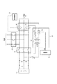
図1は、本開示の第1の実施形態に係る電力制御システムの概略構成を示すブロック図である。本実施形態に係る電力制御システムは、太陽電池11と、蓄電池12と、パワーコンディショナ20と、分電盤31と、負荷32と、発電装置33と、電流センサ40と、疑似出力部50と、リレー部60とを備える。ここで、発電装置33は、燃料電池又はガス発電機により構成される。電力制御システムは、通常は系統との連系運転を行い、系統から供給される電力と、各分散電源(太陽電池11、蓄電池12、発電装置33)からの電力とを負荷32に供給する。
1 is a block diagram showing a schematic configuration of a power control system according to a first embodiment of the present disclosure. The power control system according to the present embodiment includes a
電力制御システムは、停電時など系統からの電力供給がない場合は自立運転を行い、各分散電源(太陽電池11、蓄電池12、発電装置33)からの電力を負荷32に供給する。電力制御システムが自立運転を行う場合には、各分散電源(太陽電池11、蓄電池12、発電装置33)は系統から解列した状態である。電力制御システムが連系運転を行う場合には、各分散電源(太陽電池11、蓄電池12、発電装置33)は系統と並列した状態である。ここで系統から解列した状態とは系統と電気的に切断された状態であり、系統と並列した状態とは系統と電気的に接続した状態である。
The power control system performs a self-sustaining operation when there is no power supply from the grid, such as during a power failure, and supplies power from each distributed power source (
図1において、各機能ブロックを結ぶ実線は電力の流れる配線を表す。図1において、各機能ブロックを結ぶ破線は、制御信号又は通信される情報の流れを表す。当該破線が示す通信は有線通信としてもよいし、無線通信としてもよい。制御信号及び情報の通信には、各階層含め、様々な方式を採用可能である。例えば、ZigBee(登録商標)などの近距離通信方式による通信を採用することができる。また、制御信号及び情報の通信には、赤外線通信、電力線搬送通信(PLC:Power Line Communication)など、様々な伝送メディアを使用することができる。またそれぞれの通信に適した物理層を含む下位の層の上で、各種プロトコル、例えばZigBee、SEP2.0(Smart Energy Profile2.0)、ECHONET Lite(登録商標)、KNXなどのような論理層だけ規定される通信プロトコルを動作させてもよい。 In FIG. 1, solid lines connecting the functional blocks represent wirings through which electric power flows. In FIG. 1, a broken line connecting the functional blocks represents a flow of control signals or information to be communicated. The communication indicated by the broken line may be wired communication or wireless communication. Various methods can be adopted for communication of control signals and information, including each layer. For example, communication by a short-range communication method such as ZigBee (registered trademark) can be adopted. In addition, for transmission of control signals and information, various transmission media such as infrared communication and power line communication (PLC) can be used. In addition, only various logical layers such as ZigBee, SEP2.0 (Smart Energy Profile 2.0), ECHONET Lite (registered trademark), and KNX are provided on the lower layers including the physical layer suitable for each communication. A defined communication protocol may be operated.
太陽電池11は、太陽光のエネルギーを直流の電力に変換する。太陽電池11は、例えば光電変換セルを有する発電部がマトリクス状に接続され、所定の短絡電流(たとえば10A)を出力するように構成される。太陽電池11は、シリコン系多結晶太陽電池、シリコン系単結晶太陽電池、又はCIGS等薄膜系太陽電池等、光電変換可能なものであればその種類は制限されない。
The
蓄電池12は、鉛蓄電池、リチウムイオン電池、ニッケル水素電池、NAS電池、又はレドックスフロー電池等の蓄電池から構成される。蓄電池12は、充電された電力を放電することにより、電力を供給可能である。また、蓄電池12は、系統、太陽電池11から供給される電力に加え、発電装置33から供給される電力を充電可能である。
The
パワーコンディショナ20は、太陽電池11及び蓄電池12から供給される直流の電力と、系統及び発電装置33から供給される交流の電力との変換を行うとともに、連系運転及び自立運転の切り替え制御を行う。パワーコンディショナ20は、インバータ21と、連系運転スイッチ22及び23と、自立運転スイッチ24と、パワーコンディショナ20全体を制御する制御部25とを備える。連系運転スイッチ23は、パワーコンディショナ20外に出すよう構成してもよい。
The
インバータ21は、双方向インバータである。インバータ21は、太陽電池11及び蓄電池12から供給される直流の電力を交流の電力に変換する。また、インバータ21は、系統及び発電装置33から供給される交流の電力を直流の電力に変換する。インバータ21の前段に、太陽電池11及び蓄電池12からの直流電力を一定の電圧まで昇圧するコンバータを設けてもよい。
The
連系運転スイッチ22及び23並びに自立運転スイッチ24は、それぞれリレー、トランジスタなどにより構成され、オンまたはオフ制御される。図示の通り、自立運転スイッチ24は、発電装置33と蓄電池12との間に配される。連系運転スイッチ22及び23と自立運転スイッチ24とは、双方が同時にオン(又はオフ)とならないように、同期して切り替えられる。より詳しくは、連系運転スイッチ22、23がオンとなるとき、自立運転スイッチ24は同期してオフとなり、パワーコンディショナ20は連系運転を行う。連系運転スイッチ22及び23がオフとなるとき、自立運転スイッチ24は同期してオンとなり、パワーコンディショナ20は自立運転を行う。連系運転スイッチ22及び23並びに自立運転スイッチ24の同期制御は、連系運転スイッチ22及び23への制御信号の配線を自立運転スイッチ24に分岐させることによりハードウェア的に実現される。なお、スイッチ毎に同一の制御信号に対するオンとオフの状態を区別して設定可能なことはいうまでもない。連系運転スイッチ22及び23並びに自立運転スイッチ24の同期制御は、制御部25によりソフトウェア的に実現することも可能である。
The interconnected operation switches 22 and 23 and the self-sustained
制御部25は、例えばマイクロコンピュータで構成される。制御部25は、系統電圧の上昇や停電等の状態等に基づいて、インバータ21、連系運転スイッチ22及び23、自立運転スイッチ24等の各部の動作を制御する。制御部25は、連系運転時には、連系運転スイッチ22、23をオン、自立運転スイッチ24をオフに切り替える。制御部25は、自立運転時には、連系運転スイッチ22、23をオフ、自立運転スイッチ24をオンに切り替える。
The
分電盤31は、連系運転時に系統より供給される電力を複数の支幹に分岐させて負荷32に分配する。分電盤31は、複数の分散電源(太陽電池11、蓄電池12、発電装置33)から供給される電力を、複数の支幹に分岐させて負荷32に分配する。ここで、負荷32とは、電力を消費する電力負荷である。負荷32は、たとえば家庭内で使用されるエアコン、電子レンジ、テレビ等の各種電器製品や、商工業施設で使用される空調機や照明器具などの機械、照明設備等である。
The
発電装置33は、燃料電池又はガス発電機により構成される。燃料電池は、水素を用いて空気中の酸素との化学反応により直流の電力を発電するセルと、発電された直流電力を100Vあるいは200Vの交流電力に変換するインバータと、その他補機類とを備える。発電装置33としての燃料電池は、パワーコンディショナ20を介さずとも負荷32に対する交流電力の供給を可能とするシステムであり、必ずしもパワーコンディショナ20との接続を想定して設計されたものではなく、汎用性を有するシステムであってよい。また、ガス発電機は、所定のガスなどを燃料とするガスエンジンで発電するものである。
The
発電装置33は、対応する電流センサ40が第1方向に流れる電流を検出する間に発電を行う。発電装置33は、発電時には負荷32の消費電力に追従する負荷追従運転又は所定の定格電力値による定格運転を行う。第1方向に流れる電流は、特に限定されるものではないが、例えば、需要家施設が買電する方向に流れる電流であり、所謂、順潮流に当たるものである。負荷追従運転時の追従範囲は、例えば200〜700Wであり、定格運転時の定格電力値は、例えば700Wである。なお、発電装置33は、連系運転時に負荷32の消費電力に追従する負荷追従運転を行い、自立運転時に負荷追従運転又は定格電力値による定格運転を行ってもよい。
The
電流センサ40は、系統及び発電装置33の間を流れる電流を検出する。例えば、発電装置33が発電する電力は売電が契約上できないと規定されている場合には、電流センサ40が系統側への第2方向に流れる電流を検出したときに、発電装置33は発電を停止する。第2方向に流れる電流は、特に限定されるものではないが、例えば、需要家施設から系統へ売電する方向に流れる電流であり、所謂、逆潮流に当たるものである。電流センサ40が順潮流を検出する間、発電装置33は負荷32に自身から電力を供給できるものとして負荷追従運転又は定格運転での発電を実行する。
The
ここで、本実施形態における電力制御システムは、発電装置33と蓄電池12とが系統から解列した状態で、電流センサ40に対し、順潮流に相当する同方向の疑似的な電流(疑似電流)を、疑似出力部50を通じて流す。これにより、発電装置33を定格運転させ、発電装置33が発電する電力を蓄電池12に蓄電することが可能となる。逆に、上記のような状態で、例えば発電装置33が発電を開始しようとした場合に、発電装置33は、系統から電力を得る代わりに蓄電池12から電力を得て発電を開始することも可能である。発電装置33は、一度発電が安定すれば、自身が発電する電力の一部を用いて発電を継続することが可能である。以下、自立運転時及び連系運転時の疑似出力部50の動作について詳述する。
Here, in the power control system according to the present embodiment, in the state where the
疑似出力部50は、自立運転時に、電流センサ40に対して順潮流と同方向の電流である疑似電流を供給可能である。疑似出力部50は、正常に動作している場合、連系運転時には疑似電流を供給しない。図2は、第1の実施形態に係る電力制御システムの疑似出力部50及びリレー部60に関する配線を示す図である。疑似出力部50は、トランス51と、疑似電流負荷52とを備える。図2では一例として、系統が200Vの単相3線の場合について示している。この場合、疑似出力部50は、リレー部60を介して、インバータ21と自立運転スイッチ24との間に配線され、パワーコンディショナ20から電力供給を受ける。疑似出力部50に対して、電圧線の一方と中性線とが接続される。リレー部60は、中性線との接続点と疑似出力部50との間に設置される。疑似出力部50は、その出力が2本の電圧線それぞれに設置した電流センサ40を通るように配線される。なお、疑似出力部50は、パワーコンディショナ20とは独立した構成としてもよいし、パワーコンディショナ20と一体的に構成してもよい。図2では、疑似出力部50は、パワーコンディショナ20とは独立して構成されている。
The
トランス51は、パワーコンディショナ20からの電圧を最適な値に降下させる。図2では、トランス51は、パワーコンディショナ20から供給されたAC100Vの電圧を例えばAC5Vの電圧に降下させている。疑似電流の電圧は、適宜設定すればよく、例えば、0Vより大きく、且つ10V以下となるように設定することができる。疑似電流負荷52は、疑似出力部50内の電流調整のため適宜設けられる負荷である。疑似電流負荷52として、疑似出力部50の外部の負荷を用いてもよい。
The
リレー部60は、リレー61と、電界効果トランジスタ(Field Effect Transistor(FET))62とを備える。リレー61は、正常に動作している場合、自立運転時にオンになり、パワーコンディショナ20から供給される電流を疑似出力部50に流す。この場合、疑似出力部50は、トランス51及び疑似電流負荷52を介して、電流センサ40に疑似電流を供給する。電流センサ40は疑似電流を検出するので、発電装置33は発電を行うことが可能である。従って、自立運転時であっても、発電装置33が発電した電力を蓄電池12へ充電することが可能である。
The
リレー61は、正常に動作している場合、連系運転時にオフになり、パワーコンディショナ20から疑似出力部50へ電流を供給しない。この場合、疑似出力部50は、電流センサ40に疑似電流を供給せず、電流センサ40は疑似電流を検出しない。
When operating normally, the relay 61 is turned off during the interconnection operation, and does not supply current from the
FET62のゲート端子は、制御部25のOUT1と接続される。他の2つの端子(ソース端子、ドレイン端子)の一方は接地され、他方はリレー61と制御部25のIN1との間に接続される。FET62は、ゲート端子に対して制御部25のOUT1からハイ(H)の出力信号を受けると、オンになる。この時、制御部25は、IN1においてロー(L)の入力信号を検出し、リレー61はオンになる。すなわち、制御部25は、ハイの信号をOUT1から出力して、自立運転時にリレー61がオンになるように制御する。一方、FET62は、ゲート端子に対して制御部25のOUT1からローの出力信号を受けると、オフになる。このとき、制御部25は、IN1においてハイの入力信号を検出し、リレー61はオフになる。すなわち、制御部25は、ローの信号をOUT1から出力して、連系運転時にリレー61がオフになるように制御する。以下、制御部25のOUT1の出力状態(設定出力値)とIN1の検出状態(検出値)とに基づいた制御部25の制御について詳述する。
The gate terminal of the FET 62 is connected to OUT1 of the
図3は、第1の実施形態において、制御部25のOUT1の出力状態とIN1の検出状態とに基づいて、疑似電流の供給状態と各状態における制御部25の動作とを表にまとめた図である。No.1及びNo.2は、制御部25のOUT1からハイの信号が出力されている状態、すなわち、自立運転時の状態である。No.3及びNo.4は、制御部25のOUT1からローの信号が出力されている状態、すなわち、連系運転時の状態である。制御部25は、OUT1の出力状態とリレー部60からの検出状態とに基づき、疑似電流の供給状態が正常であるか否かを判定する。
FIG. 3 is a table in which the pseudo current supply state and the operation of the
No.1は、制御部25のOUT1からハイの信号が出力され、IN1においてローの信号が検出されている状態である。この場合、FET62は正常にオンになっており、リレー61がオンになる。従って、自立運転時に、疑似出力部50は正常に疑似電流を電流センサ40に供給可能である。すなわち、制御部25は、上記のような状態で、自立運転時に、疑似出力部50が疑似電流を供給する供給状態が正常であると判定する。この場合、制御部25は、疑似出力部50の動作を継続するように制御する。
No. 1 is a state in which a high signal is output from OUT1 of the
No.2は、制御部25のOUT1からハイの信号が出力され、IN1においてハイの信号が検出されている状態である。この場合、FET62は何らかの原因により正常にオンになっておらず、リレー61もオフになる。従って、自立運転時であるにもかかわらず、疑似出力部50は疑似電流を電流センサ40に供給することができない。すなわち、制御部25は、上記のような状態で、自立運転時に、疑似出力部50が疑似電流を供給しない供給状態が異常であると判定する。この場合、制御部25は、エラー報知を行う。制御部25がエラー報知を行う理由は、一点目に、当該エラー状態では単に疑似出力部50から疑似電流が供給されないだけであり、自立運転時でもあるので、発電装置33からの発電電力が系統に逆潮流することもないからである。従って、制御部25は、疑似出力部50の動作を継続するように制御しても問題はない。二点目に、自立運転時でもあり系統に代わる電力供給源が必要となるので、制御部25は、太陽電池11、蓄電池12、及びインバータ21を含む自立運転システムの動作についても継続するように制御する必要があるからである。これにより、パワーコンディショナ20は、自立運転時であっても負荷32に安定して電力を供給できる。
No. 2 is a state in which a high signal is output from OUT1 of the
No.3は、制御部25のOUT1からローの信号が出力され、IN1においてハイの信号が検出されている状態である。この場合、FET62は正常にオフになっており、リレー61がオフになる。従って、連系運転時に、疑似出力部50は疑似電流を電流センサ40に供給しない。すなわち、制御部25は、上記のような状態で、連系運転時に疑似出力部50が疑似電流を供給しない供給状態が正常であると判定する。この場合、制御部25は、疑似出力部50の動作を継続するように制御する。
No. 3 is a state in which a low signal is output from OUT1 of the
No.4は、制御部25のOUT1からローの信号が出力され、IN1においてローの信号が検出されている状態である。この場合、FET62は、何らかの原因、例えばショート破損により正常にオフになっておらず、リレー61もオンとなる。従って、連系運転時であるにもかかわらず、疑似出力部50は疑似電流を電流センサ40に供給することになる。すなわち、制御部25は、上記のような状態で、連系運転時に、疑似出力部50が疑似電流を供給する供給状態が異常であると判定する。この場合、制御部25は、エラー報知、連系運転停止、自立運転スイッチ24オフ、及びインバータ21停止を行う。すなわち、制御部25は、疑似出力部50の動作を継続しないように制御する。このような動作を行う理由は、系統と連系している場合に上記のような状態になると、発電装置33の発電電力が系統に逆潮流する可能性があるからである。言い換えると、上記の動作により、疑似出力部50は疑似電流を供給することもなく、発電装置33の発電電力が系統に逆潮流することを防ぐことが可能となる。
No. 4 is a state in which a low signal is output from OUT1 of the
次に、本開示の第1の実施形態に係る電力制御システムについて、図4及び図5に示すフローチャートによりその動作を説明する。電力制御システムの動作は、自立運転時と連系運転時とにおいて異なる。まず、自立運転時の動作について図4を用いて説明する。 Next, the operation of the power control system according to the first embodiment of the present disclosure will be described with reference to the flowcharts shown in FIGS. 4 and 5. The operation of the power control system is different between the independent operation and the interconnection operation. First, the operation during self-sustaining operation will be described with reference to FIG.
はじめに、制御部25は、OUT1からハイの信号を出力する(ステップS100)。
First, the
次に、制御部25は、IN1においてリレー部60からローの信号を検出しているか否かを判定する(ステップS101)。ローの信号を検出している場合には、ステップS102に進む。ローの信号を検出しない、すなわち、IN1においてリレー部60からハイの信号を検出している場合には、ステップS103に進む。
Next, the
続いて、制御部25は、IN1において検出したリレー部60からのローの信号に基づいて、疑似出力部50が疑似電流を供給する供給状態が正常であると判定する(ステップS102)。
Subsequently, the
続いて、制御部25は、正常であるとの判定に基づいて、疑似出力部50の動作を継続するように制御する(ステップS104)。その後、制御部25は、制御を終了する。
Then, the
一方、制御部25は、IN1において検出したリレー部60からのハイの信号に基づいて、疑似出力部50が疑似電流を供給しない供給状態が異常であると判定する(ステップS103)。
On the other hand, the
続いて、制御部25は、異常であるとの判定に基づいて、エラー報知を行う(ステップS105)。制御部25は、この場合、エラー報知を行い、上述の通り、疑似出力部50の動作と太陽電池11、蓄電池12、及びインバータ21を含む自立運転システムの動作とを継続するように制御する。その後、制御部25は、制御を終了する。
Subsequently, the
続いて、連系運転時の動作について図5を用いて説明する。連系運転時、制御部25は、OUT1からローの信号を出力する(ステップS200)。
Next, the operation during the interconnection operation will be described with reference to FIG. During the interconnection operation, the
次に、制御部25は、IN1においてリレー部60からハイの信号を検出しているか否かを判定する(ステップS201)。ハイの信号を検出している場合には、ステップS202に進む。ハイの信号を検出しない場合、すなわち、IN1においてリレー部60からローの信号を検出している場合には、ステップS203に進む。
Next, the
続いて、制御部25は、IN1において検出したリレー部60からのハイの信号に基づいて、疑似出力部50が疑似電流を供給しない供給状態が正常であると判定する(ステップS202)。
Subsequently, the
続いて、制御部25は、正常であるとの判定に基づいて、疑似出力部50の動作を継続するように制御する(ステップS204)。その後、制御部25は、制御を終了する。
Then, the
一方、制御部25は、IN1において検出したリレー部60からのローの信号に基づいて、疑似出力部50が疑似電流を供給する供給状態が異常であると判定する(ステップS203)。
On the other hand, the
続いて、制御部25は、異常であるとの判定に基づいて、エラー報知、連系運転停止、自立運転スイッチ24オフ、及びインバータ21停止を行う(ステップS205)。すなわち、制御部25は、疑似出力部50の動作を継続しないように制御する。これにより、疑似出力部50は疑似電流を供給することなく、発電装置33の発電電力が系統に逆潮流することを防ぐことが可能となる。その後、制御部25は、制御を終了する。
Subsequently, the
以上のような構成の第1の実施形態の電力制御システムによれば、制御部25は、自立運転時及び連系運転時に、疑似電流の供給状態が正常であるか否かを判定して、疑似出力部50の動作を継続するか否かを制御することが可能である。
According to the power control system of the first embodiment having the above-described configuration, the
これにより、自立運転時であって、疑似電流の供給状態が正常である場合は、疑似出力部50は、安定して疑似電流の供給を継続でき、発電装置33の発電も継続できる。
Accordingly, during the self-sustaining operation and when the pseudo current supply state is normal, the
また、自立運転時であって、疑似電流の供給状態が異常である場合は、制御部25は、エラー報知を行う。制御部25は、自立運転システムの動作を継続する。これにより、パワーコンディショナ20は、自立運転時であっても負荷32に安定して電力を供給することができる。
In addition, in the self-sustained operation, when the supply state of the pseudo current is abnormal, the
また、連系運転時であって、疑似電流の供給状態が正常である場合は、疑似出力部50は、疑似電流を供給せず、その動作を継続する。これにより、第1の実施形態に係る電力制御システムは、電流センサ40の本来の機能により、発電装置33の発電電力の系統への逆潮流を防ぐことができる。
Further, during the interconnection operation, and when the pseudo current supply state is normal, the
また、連系運転時であって、疑似電流の供給状態が異常である場合は、制御部25は、エラー報知、連系運転停止、自立運転スイッチ24オフ、及びインバータ21停止を行う。すなわち、疑似出力部50は動作を継続せず、疑似電流の供給が停止する。上記の動作により、第1の実施形態に係る電力制御システムは、発電装置33の発電電力の系統への逆潮流を防ぐことができる。
Further, when the pseudo current supply state is abnormal during the interconnection operation, the
(第2の実施形態)
続いて、本開示の第2の実施形態に係る電力制御システムについて説明する。第2の実施形態では、疑似電流の供給状態が正常であるか否かを判定する手法が第1の実施形態と異なる。以下に、第1の実施形態と異なる点を中心に第2の実施形態について説明する。なお、第1の実施形態と同じ機能及び構成を有する部位には同じ符号を付し、その説明を省略する。(Second embodiment)
Next, a power control system according to the second embodiment of the present disclosure will be described. The second embodiment differs from the first embodiment in the method of determining whether or not the pseudo current supply state is normal. The second embodiment will be described below, focusing on the points different from the first embodiment. It should be noted that parts having the same functions and configurations as those in the first embodiment are designated by the same reference numerals and the description thereof will be omitted.
図6は、本開示の第2の実施形態に係る電力制御システムの概略構成を示すブロック図である。本開示の第2の実施形態に係る電力制御システムは、リレー部60に代えて、リレー70を備える。
FIG. 6 is a block diagram showing a schematic configuration of a power control system according to the second embodiment of the present disclosure. The power control system according to the second embodiment of the present disclosure includes a
図7及び図8は、第2の実施形態に係る電力制御システムの疑似出力部50及びリレー70に関する配線を示す図である。図7及び図8では図2と同様に、系統は、200Vの単相3線としている。この場合、疑似出力部50は、リレー70を介して、インバータ21と自立運転スイッチ24との間に配線され、パワーコンディショナ20から電力供給を受ける。疑似出力部50に、電圧線の一方と中性線とが接続される。リレー70は、中性線との接続点と疑似出力部50との間に設置される。
7 and 8 are diagrams showing wiring for the
第2の実施形態に係る電力制御システムの疑似出力部50は、その出力を測定するための電圧センサ53(図7)又は電流センサ54(図8)をさらに備える。電圧センサ53及び電流センサ54の出力は、制御部25のIN1と接続される。
The
図7に示すとおり、電圧センサ53は、疑似電流負荷52の両端にかかる電圧差を測定する。その測定信号は制御部25のIN1に入力され、制御部25は、その測定信号に基づいて、疑似出力部50が疑似電流を供給しているか否かを判定する。
As shown in FIG. 7, the
図8に示すとおり、電流センサ54は、トランス51と電流センサ40との間に設置され、その電流値を測定する。その測定信号は制御部25のIN1に入力され、制御部25は、その測定信号に基づいて、疑似出力部50が疑似電流を供給しているか否かを判定する。
As shown in FIG. 8, the
以下、第2の実施形態に係る電力制御システムの状態と電圧センサ53又は電流センサ54の出力値とに基づいた制御部25の制御について詳述する。
Hereinafter, control of the
図9は、第2の実施形態において、第2の実施形態に係る電力制御システムの状態と電圧センサ53又は電流センサ54の出力値とに基づいて、疑似電流の供給状態と各状態における制御部25の動作とを表にまとめた図である。No.1及びNo.2は、自立運転時の状態である。No.3及びNo.4は、連系運転時の状態である。制御部25は、電圧センサ53又は電流センサ54からの出力値に基づいて、疑似電流の供給状態が正常であるか否かを判定する。
In the second embodiment, FIG. 9 is a control section in the supply state of the pseudo current and each state based on the state of the power control system according to the second embodiment and the output value of the
No.1は、自立運転時、IN1において電圧センサ53又は電流センサ54から0よりも大きい出力値が検出されている状態である。この場合、リレー70は正常にオンになっている。従って、自立運転時に、疑似出力部50は正常に疑似電流を電流センサ40に供給可能である。すなわち、制御部25は、上記のような状態で、自立運転時に、疑似出力部50が疑似電流を供給する供給状態が正常であると判定する。この場合、制御部25は、疑似出力部50の動作を継続するように制御する。
No. 1 is a state in which an output value larger than 0 is detected from the
No.2は、自立運転時、IN1において電圧センサ53又は電流センサ54から0の出力値が検出されている状態である。この場合、リレー70は何らかの原因により正常にオンになっていない。従って、自立運転時であるにもかかわらず、疑似出力部50は疑似電流を電流センサ40に供給することができない。すなわち、制御部25は、上記のような状態で、自立運転時に、疑似出力部50が疑似電流を供給しない供給状態が異常であると判定する。この場合、制御部25は、エラー報知のみを行う。エラー報知のみ行う理由は、一点目に、当該エラー状態では単に疑似出力部50から疑似電流が供給されないだけであり、自立運転時でもあるので、発電装置33からの発電電力が系統に逆潮流することもないからである。従って、制御部25は、疑似出力部50の動作を継続するように制御しても問題はない。二点目に、自立運転時でもあり系統に代わる電力供給源が必要となるので、制御部25は、太陽電池11、蓄電池12、及びインバータ21を含む自立運転システムの動作についても継続するように制御する必要があるからである。これにより、パワーコンディショナ20は、自立運転時であっても負荷32に安定して電力を供給できる。
No. 2 is a state in which the output value of 0 is detected from the
No.3は、連系運転時、IN1において電圧センサ53又は電流センサ54から0の出力値が検出されている状態である。この場合、リレー70は正常にオフになっている。従って、連系運転時に、疑似出力部50は疑似電流を電流センサ40に供給しない。すなわち、制御部25は、上記のような状態で、連系運転時に、疑似出力部50が疑似電流を供給しない供給状態が正常であると判定する。この場合、制御部25は、疑似出力部50の動作を継続するように制御する。
No. 3 is a state in which the output value of 0 is detected from the
No.4は、連系運転時、IN1において電圧センサ53又は電流センサ54から0よりも大きい出力値が検出されている状態である。この場合、リレー70は、何らかの原因、例えばショート破損により正常にオフになっていない。従って、連系運転時であるにもかかわらず、疑似出力部50は疑似電流を電流センサ40に供給することになる。すなわち、制御部25は、上記のような状態で、連系運転時に、疑似出力部50が疑似電流を供給する供給状態が異常であると判定する。この場合、制御部25は、エラー報知、連系運転停止、自立運転スイッチ24オフ、及びインバータ21停止を行う。すなわち、制御部25は、疑似出力部50の動作を継続しないように制御する。このような動作を行う理由は、系統と連系している場合に上記のような状態になると、発電装置33の発電電力が系統に逆潮流する可能性があるからである。言い換えると、上記の動作により、疑似出力部50は疑似電流を供給することもなく、発電装置33の発電電力が系統に逆潮流することを防ぐことが可能となる。
No. 4 is a state in which an output value larger than 0 is detected from the
次に、本開示の第2の実施形態に係る電力制御システムについて、図10及び図11に示すフローチャートによりその動作を説明する。電力制御システムの動作は、自立運転時と連系運転時とにおいて異なる。まず、自立運転時の動作について図10を用いて説明する。 Next, the operation of the power control system according to the second embodiment of the present disclosure will be described with reference to the flowcharts shown in FIGS. 10 and 11. The operation of the power control system is different between the independent operation and the interconnection operation. First, the operation during self-sustaining operation will be described with reference to FIG.
はじめに、制御部25は、IN1において0よりも大きい出力値を検出しているか否かを判定する(ステップS300)。0よりも大きい出力値を検出している場合には、ステップS301に進む。0よりも大きい出力値を検出しない、すなわち、IN1において電圧センサ53又は電流センサ54から0の出力値を検出している場合には、ステップS302に進む。
First, the
次に、制御部25は、IN1において検出した電圧センサ53又は電流センサ54からの0よりも大きい出力値に基づいて、疑似出力部50が疑似電流を供給する供給状態が正常であると判定する(ステップS301)。
Next, the
続いて、制御部25は、正常であるとの判定に基づいて、疑似出力部50の動作を継続するように制御する(ステップS303)。その後、制御部25は、制御を終了する。
Subsequently, the
一方、制御部25は、IN1において検出した電圧センサ53又は電流センサ54からの0の出力値に基づいて、疑似出力部50が疑似電流を供給しない供給状態が異常であると判定する(ステップS302)。
On the other hand, the
続いて、制御部25は、異常であるとの判定に基づいて、エラー報知を行う(ステップS304)。制御部25は、この場合、エラー報知を行い、疑似出力部50の動作と太陽電池11、蓄電池12、及びインバータ21を含む自立運転システムの動作とを継続するように制御する。その後、制御部25は、制御を終了する。
Subsequently, the
続いて、連系運転時の動作について図11を用いて説明する。連系運転時、制御部25は、IN1において0の出力値を検出しているか否かを判定する(ステップS400)。0の出力値を検出している場合には、ステップS401に進む。0の出力値を検出しない、すなわち、IN1において電圧センサ53又は電流センサ54から0よりも大きい出力値を検出している場合には、ステップS402に進む。
Next, the operation during interconnection operation will be described with reference to FIG. During the interconnection operation, the
次に、制御部25は、IN1において検出した電圧センサ53又は電流センサ54からの0の出力値に基づいて、疑似出力部50が疑似電流を供給しない供給状態が正常であると判定する(ステップS401)。
Next, the
続いて、制御部25は、正常であるとの判定に基づいて、疑似出力部50の動作を継続するように制御する(ステップS403)。その後、制御部25は、制御を終了する。
Then, the
一方、制御部25は、IN1において検出した電圧センサ53又は電流センサ54からの0よりも大きい出力値に基づいて、疑似出力部50が疑似電流を供給する供給状態が異常であると判定する(ステップS402)。
On the other hand, the
続いて、制御部25は、異常であるとの判定に基づいて、エラー報知、連系運転停止、自立運転スイッチ24オフ、及びインバータ21停止を行う(ステップS404)。すなわち、制御部25は、疑似出力部50の動作を継続しないように制御する。これにより、疑似出力部50は疑似電流を供給することもなく、発電装置33の発電電力が系統に逆潮流することを防ぐことが可能となる。その後、制御部25は、制御を終了する。
Subsequently, the
以上のような第2の実施形態の電力制御システムによれば、第1の実施形態の電力制御システムと同様に、制御部25は、自立運転時及び連系運転時に、疑似電流の供給状態が正常であるか否かを判定して、疑似出力部50の動作を継続するか否かを制御できる。
According to the power control system of the second embodiment as described above, as in the power control system of the first embodiment, the
これにより、自立運転時であって、疑似電流の供給状態が正常である場合は、疑似出力部50は、安定して疑似電流の供給を継続でき、発電装置33の発電も継続できる。
Accordingly, during the self-sustaining operation and when the pseudo current supply state is normal, the
また、自立運転時であって、疑似電流の供給状態が異常である場合は、制御部25は、エラー報知を行う。制御部25は、自立運転システムの動作を継続する。これにより、パワーコンディショナ20は、自立運転時であっても負荷32に安定して電力を供給することができる。
In addition, in the self-sustained operation, when the supply state of the pseudo current is abnormal, the
また、連系運転時であって、疑似電流の供給状態が正常である場合は、疑似出力部50は、疑似電流を供給せず、その動作を継続する。これにより、第1の実施形態に係る電力制御システムは、電流センサ40の本来の機能により、発電装置33の発電電力の系統への逆潮流を防ぐことができる。
Further, during the interconnection operation, and when the pseudo current supply state is normal, the
また、連系運転時であって、疑似電流の供給状態が異常である場合は、制御部25は、エラー報知、連系運転停止、自立運転スイッチ24オフ、及びインバータ21停止を行う。すなわち、疑似出力部50は動作を継続せず、疑似電流の供給が停止する。上記の動作により、第2の実施形態に係る電力制御システムは、発電装置33の発電電力の系統への逆潮流を防ぐことができる。
In addition, when the pseudo current supply state is abnormal during the interconnection operation, the
なお、図1及び図6において、電流センサ40は、パワーコンディショナ20内で、自立運転時に発電装置33の発電による電流が流れない箇所、例えば系統と連系運転スイッチ23との間に配置してもよい。これは、発電装置33の発電による電流が流れる箇所に電流センサ40を配置すると、発電装置33を発電させるための疑似電流を当該発電による電流を上回る電力で出力する必要があるため、疑似電流に関する消費電力が増大するためである。すなわち、電流センサ40を、パワーコンディショナ20において、自立運転時に発電装置33の発電による電流が流れない箇所に配置することにより、疑似電流に係る消費電力を低減することも可能である。
1 and 6, the
本開示は、その精神又はその本質的な特徴から離れることなく、上述した実施形態以外の他の所定の形態で実現できることは当業者にとって明白である。従って、先の記述は例示的なものであり、これに限定されるものではない。発明の範囲は、先の記述によってではなく、付加した請求項によって定義される。あらゆる変更のうちその均等の範囲内にあるいくつかの変更は、その中に包含されるものとする。 It will be apparent to those skilled in the art that the present disclosure can be implemented in other specific forms than the above-described embodiments without departing from the spirit or the essential characteristics thereof. Therefore, the above description is illustrative and not restrictive. The scope of the invention is defined by the appended claims rather than by the preceding description. All changes, which are within their equivalent scope, are to be included therein.
11 太陽電池
12 蓄電池
20 パワーコンディショナ
21 インバータ
22、23 連系運転スイッチ
24 自立運転スイッチ
25 制御部
31 分電盤
32 負荷
33 発電装置
40、54 電流センサ
50 疑似出力部
51 トランス
52 疑似電流負荷
53 電圧センサ
60 リレー部
61、70 リレー
62 電界効果トランジスタ(Field Effect Transistor(FET))
Claims (15)
前記電流センサが検出可能な第2配線に電流を供給可能に接続され、自立運転時には前記電流センサが検出するように前記順潮流に相当する疑似電流を前記第2配線に供給し、連系運転時には前記疑似電流を前記第2配線に供給しない疑似出力部と、
前記疑似出力部と通信を行い、前記疑似電流の供給状態が正常であるか否かを判定して、前記疑似出力部の動作を継続するか否かを制御する制御部と、を備え、
前記制御部は、
前記供給状態が、前記自立運転時に前記疑似電流が前記第2配線に供給される状態又は前記連系運転時に前記疑似電流が前記第2配線に供給されない状態であり、正常であると判定した場合に、前記疑似出力部の動作を継続し、
前記供給状態が、前記自立運転時に前記疑似電流が前記第2配線に供給されない状態であり、正常でないと判定した場合に、エラー報知を行い、前記疑似出力部に前記疑似電流を前記第2配線に供給させる制御において、さらなる制御は行わず、
前記供給状態が、前記連系運転時に前記疑似電流が前記第2配線に供給される状態であり、正常でないと判定した場合に、エラー報知を行い、前記疑似出力部の動作を継続しないことを特徴とする、
電力制御システム。 Current sensor provided on the first wiring between the distribution board and the system power generating device and the load is connected to supply power to the load while detecting the forward power flow from the grid, to the system The power generator that stops power generation while detecting the reverse power flow of
A current is connected to a second wiring that can be detected by the current sensor, and a pseudo current corresponding to the forward power flow is supplied to the second wiring so that the current sensor detects the current during self-sustaining operation, and the interconnection operation is performed. Sometimes a pseudo output section that does not supply the pseudo current to the second wiring ,
A control unit that communicates with the pseudo output unit, determines whether the supply state of the pseudo current is normal, and controls whether to continue the operation of the pseudo output unit;
The control unit is
When it is determined that the supply state is normal and the pseudo current is supplied to the second wiring during the self-sustaining operation or the pseudo current is not supplied to the second wiring during the interconnection operation. , Continue the operation of the pseudo output unit,
When the supply state is a state in which the pseudo current is not supplied to the second wiring during the self-sustaining operation and it is determined that the pseudo wiring is not normal, an error is notified and the pseudo current is supplied to the pseudo output unit by the second wiring. In the control to be supplied to the
When the supply state is a state in which the pseudo current is supplied to the second wiring during the interconnection operation, and it is determined that it is not normal, an error is notified and the operation of the pseudo output unit is not continued. Characteristic,
Power control system.
前記制御部は、前記リレーをオン又はオフにするために前記制御部から出力される設定出力値と、前記設定出力値に応じて前記リレー部から入力する検出値とに基づき、前記供給状態が正常であるか否かを判定することを特徴とする、
請求項1に記載の電力制御システム。 A relay unit connected between the first wiring between the system and the distribution board and the pseudo output unit, wherein a relay is turned on during the self-sustained operation, and the relay is turned off during the interconnection operation. Further preparation,
The control unit, based on a set output value output from the control unit for turning on or off the relay, and a detection value input from the relay unit according to the set output value, the supply state is Characterized by determining whether it is normal,
The power control system according to claim 1.
請求項2に記載の電力制御システム。 The control unit outputs a high signal as the set output value during the self-sustaining operation, and if the detected value is a low signal, determines that the supply state is normal, and determines the operation of the pseudo output unit. Characterized by continuing,
The power control system according to claim 2.
請求項2に記載の電力制御システム。 The control unit outputs a high signal as the set output value during the self-sustaining operation, and if the detected value is a high signal, determines that the supply state is not normal, issues an error notification, and outputs the pseudo output. Characterized by continuing the operation of the section,
The power control system according to claim 2.
請求項2に記載の電力制御システム。 The control unit outputs a low signal as the set output value during the interconnection operation, and if the detected value is a high signal, determines that the supply state is normal, and operates the pseudo output unit. Characterized by continuing,
The power control system according to claim 2.
請求項2に記載の電力制御システム。 The control unit outputs a low signal as the set output value during the interconnection operation, and if the detected value is a low signal, determines that the supply state is not normal, notifies an error, and outputs the pseudo signal. Characterized in that the operation of the output unit is not continued,
The power control system according to claim 2.
前記制御部は、前記電圧センサ又は前記第2の電流センサからの出力値に基づいて、前記供給状態が正常であるか否かを判定することを特徴とする、
請求項1に記載の電力制御システム。 The pseudo output unit further comprises a voltage sensor or a second current sensor for measuring an output from the pseudo output unit,
The control unit determines whether the supply state is normal, based on an output value from the voltage sensor or the second current sensor,
The power control system according to claim 1.
請求項7に記載の電力制御システム。 During the self-sustaining operation, the control unit determines that the supply state is not normal when the output value is 0, and determines that the supply state is normal when the output value is greater than 0. And
The power control system according to claim 7.
請求項7に記載の電力制御システム。 During the interconnection operation, the control unit determines that the supply state is normal when the output value is 0, and determines that the supply state is not normal when the output value is greater than 0. Characteristic,
The power control system according to claim 7.
前記疑似出力部が、自立運転時には前記電流センサが検出するように前記順潮流に相当する疑似電流を前記第2配線に供給し、連系運転時には前記疑似電流を前記第2配線に供給しないステップと、
前記制御部が、前記疑似出力部と通信を行い、前記疑似電流の供給状態が正常であるか否かを判定して、前記供給状態を継続するか否かを制御する制御ステップと、を含み、
前記制御ステップにおいて、前記制御部は、
前記供給状態が、前記自立運転時に前記疑似電流が前記第2配線に供給される状態又は前記連系運転時に前記疑似電流が前記第2配線に供給されない状態であり、正常であると判定した場合に、前記供給状態を継続し、
前記供給状態が、前記自立運転時に前記疑似電流が前記第2配線に供給されない状態であり、正常でないと判定した場合に、エラー報知を行い、前記疑似出力部に前記疑似電流を前記第2配線に供給させる制御において、さらなる制御は行わず、
前記供給状態が、前記連系運転時に前記疑似電流が前記第2配線に供給される状態であり、正常でないと判定した場合に、エラー報知を行い、前記供給状態を継続しない、
電力制御システムの制御方法。 Current sensor provided on the first wiring between the distribution board and the system power generating device and the load is connected to supply power to the load while detecting the forward power flow from the grid, to the system Power control system including the power generation device that stops power generation while detecting the reverse power flow of the device, a pseudo output unit connected to the second wiring that can be detected by the current sensor so as to be able to supply current, and a control unit. Control method of
A step in which the pseudo output section supplies a pseudo current corresponding to the forward power flow to the second wiring so as to be detected by the current sensor during a self-sustaining operation, and does not supply the pseudo current to the second wiring during an interconnection operation; When,
A control step in which the control unit communicates with the pseudo output unit, determines whether or not the supply state of the pseudo current is normal, and controls whether or not to continue the supply state; ,
In the control step, the control unit is
When it is determined that the supply state is normal and the pseudo current is supplied to the second wiring during the self-sustaining operation or the pseudo current is not supplied to the second wiring during the interconnection operation. To continue the supply state,
When the supply state is a state in which the pseudo current is not supplied to the second wiring during the self-sustaining operation and it is determined that it is not normal, an error is notified and the pseudo current is supplied to the pseudo output unit by the second wiring. In the control to be supplied to the
The supply state is a state in which the pseudo current is supplied to the second wiring during the interconnection operation, and when it is determined that it is not normal, an error is notified and the supply state is not continued,
Power control system control method.
前記制御ステップにおいて、前記制御部は、前記リレーをオン又はオフにするために前記制御部から出力される設定出力値と、前記設定出力値に応じて前記リレー部から入力する検出値と、に基づき、前記供給状態が正常であるか否かを判定する、
請求項10に記載の電力制御システムの制御方法。 The power control system is connected between the first wiring between the grid and the distribution board and the pseudo output unit, a relay is turned on during the self-sustained operation, and the relay is turned on during the interconnected operation. Further equipped with a relay section that turns off,
In the control step, the control unit sets a set output value output from the control unit for turning on or off the relay, and a detection value input from the relay unit according to the set output value. Based on whether the supply state is normal,
The control method of the power control system according to claim 10.
前記制御ステップにおいて、前記制御部は、前記検出値がローの信号であれば前記供給状態が正常であると判定して、前記供給状態を継続する、
請求項11に記載の電力制御システムの制御方法。 The control unit further includes a step of outputting a high signal as the set output value during the self-sustaining operation,
In the control step, the control unit determines that the supply state is normal if the detected value is a low signal, and continues the supply state,
The control method of the power control system according to claim 11.
前記制御ステップにおいて、前記制御部は、前記検出値がハイの信号であれば前記供給状態が正常でないと判定して、エラー報知を行い、前記供給状態を継続する、
請求項11に記載の電力制御システムの制御方法。 The control unit further includes a step of outputting a high signal as the set output value during the self-sustaining operation,
In the control step, the control unit determines that the supply state is not normal if the detection value is a high signal, performs error notification, and continues the supply state,
The control method of the power control system according to claim 11.
前記制御ステップにおいて、前記制御部は、前記検出値がハイの信号であれば前記供給状態が正常であると判定して、前記供給状態を継続する、
請求項11に記載の電力制御システムの制御方法。 The control unit further includes a step of outputting a low signal as the set output value during the interconnection operation,
In the control step, the control unit determines that the supply state is normal if the detected value is a high signal, and continues the supply state,
The control method of the power control system according to claim 11.
前記制御ステップにおいて、前記制御部は、前記検出値がローの信号であれば前記供給状態が正常でないと判定して、エラー報知を行い、前記供給状態を継続しない、
請求項11に記載の電力制御システムの制御方法。
The control unit further includes a step of outputting a low signal as the set output value during the interconnection operation,
In the control step, the control unit determines that the supply state is not normal if the detected value is a low signal, issues an error notification, and does not continue the supply state,
The control method of the power control system according to claim 11.
Applications Claiming Priority (3)
| Application Number | Priority Date | Filing Date | Title |
|---|---|---|---|
| JP2015212410 | 2015-10-28 | ||
| JP2015212410 | 2015-10-28 | ||
| PCT/JP2016/004752 WO2017073076A1 (en) | 2015-10-28 | 2016-10-28 | Power control system and control method for power control system |
Publications (2)
| Publication Number | Publication Date |
|---|---|
| JPWO2017073076A1 JPWO2017073076A1 (en) | 2018-06-07 |
| JP6731417B2 true JP6731417B2 (en) | 2020-07-29 |
Family
ID=58630212
Family Applications (1)
| Application Number | Title | Priority Date | Filing Date |
|---|---|---|---|
| JP2017547631A Active JP6731417B2 (en) | 2015-10-28 | 2016-10-28 | Power control system and control method of power control system |
Country Status (4)
| Country | Link |
|---|---|
| US (1) | US10910839B2 (en) |
| EP (1) | EP3370320A4 (en) |
| JP (1) | JP6731417B2 (en) |
| WO (1) | WO2017073076A1 (en) |
Families Citing this family (1)
| Publication number | Priority date | Publication date | Assignee | Title |
|---|---|---|---|---|
| JP6450403B2 (en) * | 2015-01-28 | 2019-01-09 | 京セラ株式会社 | Power control apparatus, power control system, and power control method |
Family Cites Families (11)
| Publication number | Priority date | Publication date | Assignee | Title |
|---|---|---|---|---|
| JP3722901B2 (en) * | 1996-01-26 | 2005-11-30 | 株式会社東芝 | Solar power system |
| JP3749139B2 (en) | 2001-04-23 | 2006-02-22 | 三洋電機株式会社 | Inverter protection device |
| JP4258468B2 (en) * | 2004-12-28 | 2009-04-30 | オムロン株式会社 | Inverter |
| JP2007049770A (en) | 2005-08-05 | 2007-02-22 | Toshiba Kyaria Kk | Power supply |
| JP4979435B2 (en) | 2007-03-30 | 2012-07-18 | 新電元工業株式会社 | Power storage device |
| JP5766097B2 (en) * | 2011-11-15 | 2015-08-19 | 京セラ株式会社 | Power conditioner, control method for power conditioner, and power conditioner system |
| JP5888101B2 (en) * | 2012-05-09 | 2016-03-16 | 株式会社デンソー | Control device |
| JP6227885B2 (en) | 2013-04-19 | 2017-11-08 | 京セラ株式会社 | Power control system, power control apparatus, and control method for power control system |
| EP3079216A4 (en) * | 2013-12-02 | 2017-08-16 | Kyocera Corporation | Power control system, power control device, and method for controlling power control system |
| WO2015111410A1 (en) * | 2014-01-22 | 2015-07-30 | 京セラ株式会社 | Power control system and method for controlling power control system |
| JP6216066B2 (en) * | 2014-07-29 | 2017-10-18 | 京セラ株式会社 | Power control system control method, power control system, and power control apparatus |
-
2016
- 2016-10-28 EP EP16859314.3A patent/EP3370320A4/en active Pending
- 2016-10-28 US US15/771,696 patent/US10910839B2/en active Active
- 2016-10-28 WO PCT/JP2016/004752 patent/WO2017073076A1/en active Application Filing
- 2016-10-28 JP JP2017547631A patent/JP6731417B2/en active Active
Also Published As
| Publication number | Publication date |
|---|---|
| EP3370320A4 (en) | 2019-03-20 |
| EP3370320A1 (en) | 2018-09-05 |
| US20180337533A1 (en) | 2018-11-22 |
| US10910839B2 (en) | 2021-02-02 |
| JPWO2017073076A1 (en) | 2018-06-07 |
| WO2017073076A1 (en) | 2017-05-04 |
Similar Documents
| Publication | Publication Date | Title |
|---|---|---|
| JP6686200B2 (en) | Power control device, power control device control method, power control system, and power control system control method | |
| JP6227885B2 (en) | Power control system, power control apparatus, and control method for power control system | |
| JP6170183B2 (en) | Power control system and control method of power control system | |
| JP6251288B2 (en) | Power control system, power control apparatus, and control method for power control system | |
| JP2016092850A (en) | Control method of power supply system, power supply apparatus and power supply system | |
| JP6731417B2 (en) | Power control system and control method of power control system | |
| JP6204259B2 (en) | Power control system, power control apparatus, and power control method | |
| WO2016017124A1 (en) | Control method for power control system, power control system, and power control device | |
| JP6582113B2 (en) | Power control apparatus, power control system, and control method for power control system | |
| JP6704479B2 (en) | POWER SUPPLY SYSTEM, POWER SUPPLY DEVICE, AND POWER SUPPLY SYSTEM CONTROL METHOD | |
| JP6694930B2 (en) | Power control system control method, power control system, and power control device | |
| EP3136536B1 (en) | Power control device, power control method, and power control system | |
| JP6475286B2 (en) | Power control apparatus, power control system, and control method for power control system | |
| JP6208617B2 (en) | Power control system, power control apparatus, and control method of power control system |
Legal Events
| Date | Code | Title | Description |
|---|---|---|---|
| A621 | Written request for application examination |
Free format text: JAPANESE INTERMEDIATE CODE: A621 Effective date: 20180220 |
|
| A131 | Notification of reasons for refusal |
Free format text: JAPANESE INTERMEDIATE CODE: A131 Effective date: 20190423 |
|
| A521 | Request for written amendment filed |
Free format text: JAPANESE INTERMEDIATE CODE: A523 Effective date: 20190607 |
|
| A131 | Notification of reasons for refusal |
Free format text: JAPANESE INTERMEDIATE CODE: A131 Effective date: 20191203 |
|
| A521 | Request for written amendment filed |
Free format text: JAPANESE INTERMEDIATE CODE: A523 Effective date: 20200123 |
|
| TRDD | Decision of grant or rejection written | ||
| A01 | Written decision to grant a patent or to grant a registration (utility model) |
Free format text: JAPANESE INTERMEDIATE CODE: A01 Effective date: 20200623 |
|
| A61 | First payment of annual fees (during grant procedure) |
Free format text: JAPANESE INTERMEDIATE CODE: A61 Effective date: 20200706 |
|
| R150 | Certificate of patent or registration of utility model |
Ref document number: 6731417 Country of ref document: JP Free format text: JAPANESE INTERMEDIATE CODE: R150 |