EP3370246A1 - Leistungsschalter und blende davon - Google Patents
Leistungsschalter und blende davon Download PDFInfo
- Publication number
- EP3370246A1 EP3370246A1 EP16858885.3A EP16858885A EP3370246A1 EP 3370246 A1 EP3370246 A1 EP 3370246A1 EP 16858885 A EP16858885 A EP 16858885A EP 3370246 A1 EP3370246 A1 EP 3370246A1
- Authority
- EP
- European Patent Office
- Prior art keywords
- baffle
- arc
- static contact
- arc angle
- circuit
- Prior art date
- Legal status (The legal status is an assumption and is not a legal conclusion. Google has not performed a legal analysis and makes no representation as to the accuracy of the status listed.)
- Granted
Links
Images


Classifications
-
- H—ELECTRICITY
- H01—ELECTRIC ELEMENTS
- H01H—ELECTRIC SWITCHES; RELAYS; SELECTORS; EMERGENCY PROTECTIVE DEVICES
- H01H73/00—Protective overload circuit-breaking switches in which excess current opens the contacts by automatic release of mechanical energy stored by previous operation of a hand reset mechanism
- H01H73/02—Details
- H01H73/18—Means for extinguishing or suppressing arc
-
- H—ELECTRICITY
- H01—ELECTRIC ELEMENTS
- H01H—ELECTRIC SWITCHES; RELAYS; SELECTORS; EMERGENCY PROTECTIVE DEVICES
- H01H9/00—Details of switching devices, not covered by groups H01H1/00 - H01H7/00
- H01H9/30—Means for extinguishing or preventing arc between current-carrying parts
- H01H2009/305—Means for extinguishing or preventing arc between current-carrying parts including means for screening for arc gases as protection of mechanism against hot arc gases or for keeping arc gases in the arc chamber
-
- H—ELECTRICITY
- H01—ELECTRIC ELEMENTS
- H01H—ELECTRIC SWITCHES; RELAYS; SELECTORS; EMERGENCY PROTECTIVE DEVICES
- H01H9/00—Details of switching devices, not covered by groups H01H1/00 - H01H7/00
- H01H9/30—Means for extinguishing or preventing arc between current-carrying parts
- H01H9/46—Means for extinguishing or preventing arc between current-carrying parts using arcing horns
Definitions
- the present invention relates to the field of low voltage electrical apparatus, more particularly, to a baffle for cutting off arcs and airflow in a circuit breaker.
- the volume of circuit breaker products is getting smaller and smaller, but the technical performance indexes are getting higher and higher.
- the high-temperature expansion gas generated by an arc during a short circuit breaking process will interfere with the arc in a limited space.
- the high-temperature expansion gas will prevent the arc from effectively entering into an arc extinguishing chamber, resulting in a longer staying time of the arc outside the arc extinguishing chamber.
- the long time staying of the arc outside the arc extinguishing chamber for example, staying in an arc channel will cause a longer breaking time and reduction in performance indexes.
- the long time staying arc will also cause severe burning of an arcing plate, a movable contact and a static contact.
- the mounting switch comprises a housing, a contact assembly in the pre-chamber, an arc extinguishing chamber, and first and second arc guides.
- the contact assembly comprises a static contact and a movable contact.
- the first and second arc guides lead the arc generated at the contact assembly at the time of switching on to the arc extinguishing chamber.
- the first arc guide is associated with the static contact, wherein the pre-chamber has a plurality of protruding guide ribs on at least one sub-surface inside the housing.
- the protruding guide ribs are arranged from an area of the contact assembly to an area of the arc extinguishing chamber approximately along the direction of travel of the arc.
- the pre-chamber has, on at least one sub-surface inside the housing, protruding tabs with an annular closed peripheral contour in the area of the static contact.
- the protruding tabs are arranged between the guide ribs adjacent to the static contact and the first arc guide, so that a circulation of gas flowing around the tab may be configured between the guide rib adjacent to the static contact and the first arc guide.
- the circuit breaker disclosed in CN103123872A considers the phenomenon of arc backflow in the arc angle area of the static contact, and designs a return circulation structure in the static contact and the arc angle area.
- the circuit breaker of CN103123872A guides the airflow inside the arc angle area, reduces the backflow of the airflow inside the arc angle area, and mitigates the obstruction of the arc entering into the arc extinguishing chamber caused by the airflow in the arc angle area.
- the airflow close to the arc angle, especially the airflow just above the arc angle will also have a significant influence on the arc.
- CN103123872A does not perform any treatment on the airflow outside the arc angle area, so the arc will still stay for a long time as a result of the impact of the airflow in this area.
- the invention proposes a baffle of a circuit breaker and a circuit breaker utilizing the baffle.
- the baffle can cut off an airflow inside and outside an arc angle zone of a static contact.
- a baffle of a circuit-breaker is provided.
- the baffles are provided on both sides of a housing of the circuit-breaker, wherein the baffle on one side is located inside an arc angle of a static contact, and the baffle cuts off a space inside the arc angle of the static contact.
- a first baffle is provided on one side of the housing on which the static contact is located, the first baffle is located inside the arc angle of the static contact, and the first baffle cuts off an arc and/or an airflow.
- a second baffle provided on the other side of the housing cuts off an arc and/or an airflow.
- At least one of the first baffle and the second baffle is a straight edge baffle, and the straight edge baffle crosses the arc angle of the static contact so as to cut off the space inside the arc angle of the static contact.
- At least one of the first baffle and the second baffle is an arc-shaped baffle, and the arc-shaped baffle occupies the arc angle of the static contact so as to cut off the space inside the arc angle of the static contact.
- a circuit breaker is provided.
- Baffles are provided on both sides of a housing of the circuit-breaker, wherein the baffle on one side is located inside an arc angle of a static contact, and the baffle cuts off a space inside the arc angle of the static contact.
- the baffles on both sides have a symmetrical structure.
- a first baffle is provided on one side of the housing on which the static contact is located, the first baffle is located inside the arc angle of the static contact, and the first baffle cuts off an arc and/or an airflow, a second baffle provided on the other side of the housing cuts off an arc and/or an airflow.
- At least one of the first baffle and the second baffle is a straight edge baffle, and the straight edge baffle crosses the arc angle of the static contact so as to cut off the space inside the arc angle of the static contact.
- At least one of the first baffle and the second baffle is an arc-shaped baffle, and the arc-shaped baffle occupies the arc angle of the static contact so as to cut off the space inside the arc angle of the static contact.
- the baffle of the present invention can solve the problem that during a process of short-circuit breaking, high-temperature gas returns from a side of the arc angle of the static contact back to a place between a movable contact and the static contact, driving the arc to repeatedly move within an arc channel, resulting in a long breaking time and severe burning of the movable contact and the static contact.
- the baffle can effectively cut off an airflow and the arc, so that the arc can effectively enter an extinguishing arc chamber for extinguishing.
- the breaking time is significantly shortened, the breaking effect is better.
- the structure at the arc angle position of the static contact needs to be optimized. Not only the influence of the airflow inside the arc angle area shall be considered, the influence of the airflow outside the arc angle area shall be considered as well.
- a baffle is arranged in the arc angle area of the static contact, and the baffle cuts off the space inside the arc angle area.
- baffle with a symmetrical structure is arranged on the other side of the housing at a position corresponding to the arc angle area, so that both the airflow inside the arc angle area and outside the arc angle area can be cut off, and the arc backflow phenomenon in the arc angle area can be reduced.
- the arc can effectively enter into the arc extinguishing chamber for arc extinguishing.
- the circuit breaker is provided with baffles on both sides of a housing of the circuit-breaker, wherein the baffle on one side is located inside an arc angle of a static contact, and the baffle cuts off a space inside the arc angle of the static contact.
- the baffle may have various shapes that can realize the function of cutting off the space inside the arc angle.
- the baffle on the other side has a symmetrical structure.
- the term "symmetrical structure" means that the other baffle on the other side is arranged in a symmetrical position, that is, a corresponding position on the other side of the housing and has a corresponding size.
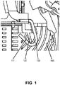
- FIG. 1 illustrates a structural diagram of a baffle of a circuit breaker according to an embodiment of the present invention.
- the baffle 101 provided on the housing 103 is a straight edge baffle 111.
- the straight edge baffle 111 crosses the arc angle 102 of the static contact so as to cut off the space inside the arc angle 102 of the static contact.
- the straight edge baffle 111 longitudinally crosses the arc angle 102 and separates the space within the arc angle 102 into two parts which are separated from each other.
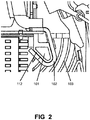
- FIG. 2 illustrates a structural diagram of a baffle of a circuit breaker according to another embodiment of the present invention.
- the baffle 101 provided on the housing 103 is an arc-shaped baffle 112.
- the arc-shaped baffle 112 occupies the arc angle 102 of the static contact so as to cut off the space inside the arc angle 102 of the static contact.
- the arc-shaped baffle 112 has a shape that matches the arc angle 102, and the arc-shaped baffle 112 occupies the space inside the arc angle 102.
- baffles may be any shape which can realize the function of cutting off the space inside the arc angle.
- the first baffle is provided on the side of the housing on which the static contact is located, and the first baffle is located inside the arc angle of the static contact.
- the second baffle is provided on the other side of the housing.
- the first baffle and the second baffle have a symmetrical structure. That is, assuming that there is a symmetrical "virtual" static contact on the other side of the housing, the second baffle is located exactly in the arc angle of the "virtual" static contact and cuts off the space inside the arc angle.
- the first baffle and the second baffle both have the function of cutting off an arc and/or an airflow.
- the present invention also provides a circuit breaker utilizing the baffle mentioned above.
- Baffles are provided on both sides of a housing of the circuit-breaker.
- the baffle on one side is located inside an arc angle of a static contact, and the baffle cuts off a space inside the arc angle of the static contact.
- the baffles on both sides have a symmetrical structure.
- the first baffle is provided on the side of the housing on which the static contact is located, and the first baffle is located inside the arc angle of the static contact.
- the second baffle is provided on the other side of the housing.
- the first baffle and the second baffle both have the function of cutting off an arc and/or an airflow.
- Each of the baffles may be a straight edge baffle as shown in FIG. 1 , or an arc-shaped baffle as shown in FIG. 2 .
- the baffles also may have other shapes that can realize the function of cutting off the space inside the arc angle.
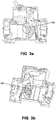
- FIG. 3a and FIG. 3b illustrate a structural diagram of a circuit breaker according to an embodiment of the present invention.
- the first baffle and the second baffle provided on different sides of the housing of the circuit breaker have a same shape, and are located at symmetrical positions. Both of the first baffle and the second baffle are straight edge baffles.
- the first baffle 301 provided on the side of the housing on which the static contact is located is a straight edge baffle
- the first baffle 301 cuts off an arc and/or an airflow.
- Arrows in FIG. 3a show paths of the arc and/or the airflow.
- FIG. 3a show paths of the arc and/or the airflow.
- the second baffle 302 provided on the other side of the housing is also a straight edge baffle.
- the second baffle 302 is arranged in a symmetrical position with the first baffle 301.
- the second baffle 302 cuts off an arc and/or an airflow. Arrows in FIG. 3b show paths of the arc and/or the airflow.
- FIG. 4a and FIG. 4b illustrate a structural diagram of a circuit breaker according to another embodiment of the present invention.
- the first baffle and the second baffle provided on different sides of the housing of the circuit breaker have a same shape, and are located at symmetrical positions.
- the first baffle and the second baffle are both arc-shaped baffles.
- the first baffle 401 provided on the side of the housing on which the static contact is located is an arc-shaped baffle
- the first baffle 301 cuts off an arc and/or an airflow.
- Arrows in FIG. 4a show paths of the arc and/or the airflow.
- FIG. 4a show paths of the arc and/or the airflow.
- the second baffle 402 provided on the other side of the housing is also an arc-shaped baffle.
- the second baffle 402 is arranged in a symmetrical position with the first baffle 401.
- the second baffle 402 cuts off an arc and/or an airflow. Arrows in FIG. 4b show paths of the arc and/or the airflow.
- FIG. 5a and FIG. 5b illustrate a structural diagram of a circuit breaker according to a further embodiment of the present invention.
- the first baffle and the second baffle provided on different sides of the housing of the circuit breaker have different shapes, but are located at symmetrical positions and have corresponding sizes.
- the first baffle 501 provided on the side of the housing on which the static contact is located is a straight edge baffle, the straight edge first baffle 501 cuts off an arc and/or an airflow.
- Arrows in FIG. 5a show paths of the arc and/or the airflow.
- FIG. 5a show paths of the arc and/or the airflow.
- the second baffle 502 provided on the other side of the housing is an arc-shaped baffle.
- the arc-shaped second baffle 502 cuts off an arc and/or an airflow.
- Arrows in FIG. 5b show paths of the arc and/or the airflow.
- FIG. 5a and FIG. 5b better explain the meaning of the term "symmetrical structure" of the present invention.
- the symmetrical structure means that the second baffle on the other side is arranged in a symmetrical position with the first baffle. That is, the second baffle is arranged in a corresponding position on the other side of the housing and has a corresponding size.
- the second baffle is located exactly in the arc angle of the "virtual" static contact and cuts off the space inside the arc angle.
- the term “symmetrical” here refers to the corresponding mounting positions and sizes of the baffles, while the shapes of the baffle are not required to be exactly the same.
- the baffle of the present invention can solve the problem that during a process of short-circuit breaking, high-temperature gas returns from a side of the arc angle of the static contact back to a place between a movable contact and the static contact, driving the arc to repeatedly move within an arc channel, resulting in a long breaking time and severe burning of the movable contact and the static contact.
- the baffle can effectively cut off an airflow and the arc, so that the arc can effectively enter an extinguishing arc chamber for extinguishing.
- the breaking time is significantly shortened, the breaking effect is better.
Landscapes
- Arc-Extinguishing Devices That Are Switches (AREA)
- Breakers (AREA)
Applications Claiming Priority (2)
| Application Number | Priority Date | Filing Date | Title |
|---|---|---|---|
| CN201510728363.1A CN105185671B (zh) | 2015-10-30 | 2015-10-30 | 断路器及其挡板 |
| PCT/CN2016/100722 WO2017071449A1 (zh) | 2015-10-30 | 2016-09-29 | 断路器及其挡板 |
Publications (3)
| Publication Number | Publication Date |
|---|---|
| EP3370246A1 true EP3370246A1 (de) | 2018-09-05 |
| EP3370246A4 EP3370246A4 (de) | 2019-06-19 |
| EP3370246B1 EP3370246B1 (de) | 2020-08-26 |
Family
ID=54907681
Family Applications (1)
| Application Number | Title | Priority Date | Filing Date |
|---|---|---|---|
| EP16858885.3A Active EP3370246B1 (de) | 2015-10-30 | 2016-09-29 | Leistungsschalter und blende davon |
Country Status (6)
| Country | Link |
|---|---|
| EP (1) | EP3370246B1 (de) |
| KR (1) | KR102705657B1 (de) |
| CN (1) | CN105185671B (de) |
| BR (1) | BR112018008400B1 (de) |
| RU (1) | RU2700790C1 (de) |
| WO (1) | WO2017071449A1 (de) |
Families Citing this family (1)
| Publication number | Priority date | Publication date | Assignee | Title |
|---|---|---|---|---|
| CN105185671B (zh) * | 2015-10-30 | 2019-06-25 | 上海电科电器科技有限公司 | 断路器及其挡板 |
Family Cites Families (21)
| Publication number | Priority date | Publication date | Assignee | Title |
|---|---|---|---|---|
| ATE115767T1 (de) * | 1989-03-13 | 1994-12-15 | Licentia Gmbh | Selbstschalter, insbesondere leitungsschutzschalter. |
| FR2828329B1 (fr) * | 2001-07-31 | 2003-12-12 | Legrand Sa | Dispositif pour l'extinction d'un arc electrique |
| CN1758396A (zh) * | 2004-12-27 | 2006-04-12 | 常熟开关制造有限公司(原常熟开关厂) | 自动转换开关的灭弧装置 |
| JP4529769B2 (ja) * | 2005-04-05 | 2010-08-25 | 三菱電機株式会社 | 回路遮断器 |
| CN2924772Y (zh) * | 2005-12-05 | 2007-07-18 | 北京Abb低压电器有限公司 | 用于微型断路器的静触座、灭弧系统及微型断路器 |
| CN200990306Y (zh) * | 2006-11-30 | 2007-12-12 | Tcl低压电器(无锡)有限公司 | 利于灭弧的吹弧结构 |
| DE602007006940D1 (de) * | 2007-07-26 | 2010-07-15 | Bticino Spa | Differentialschutzblock für einen elektrischen Schalter |
| RU2391737C1 (ru) * | 2008-12-15 | 2010-06-10 | Общество с ограниченной ответственностью "Технос" | Выключатель автоматический быстродействующий |
| JP2011014350A (ja) * | 2009-07-01 | 2011-01-20 | Mitsubishi Electric Corp | 回路遮断器 |
| CN201663133U (zh) * | 2010-04-08 | 2010-12-01 | 温州科宇电器有限公司 | 小型断路器灭弧装置 |
| CN201780948U (zh) * | 2010-09-13 | 2011-03-30 | 赵建平 | 一种低压电器断路器引弧机构 |
| DE102011118968B3 (de) * | 2011-11-19 | 2013-01-31 | Abb Ag | Installationsschaltgerät mit Vorkammerraum und Leitrippen |
| CN203013659U (zh) * | 2012-12-27 | 2013-06-19 | 德力西电气有限公司 | 一种带跑弧道的断路器 |
| WO2014155442A1 (ja) * | 2013-03-27 | 2014-10-02 | パナソニック株式会社 | 回路遮断器 |
| RU139886U1 (ru) * | 2013-10-11 | 2014-04-27 | Общество с ограниченной ответственностью "ИЭК ХОЛДИНГ" | Автоматический выключатель модульного исполнения |
| CN203859087U (zh) * | 2014-05-12 | 2014-10-01 | 乐清市华洛电器有限公司 | 一种带过电流保护的剩余电流动作断路器 |
| RU148761U1 (ru) * | 2014-07-15 | 2014-12-20 | Закрытое акционерное общество "Курский электроаппаратный завод" (ЗАО "КЭАЗ") | Выключатель автоматический |
| CN204257457U (zh) * | 2014-11-13 | 2015-04-08 | 浙江正泰电器股份有限公司 | 断路器灭弧机构 |
| CN205231002U (zh) * | 2015-10-30 | 2016-05-11 | 上海电科电器科技有限公司 | 断路器及其挡板 |
| CN105185671B (zh) * | 2015-10-30 | 2019-06-25 | 上海电科电器科技有限公司 | 断路器及其挡板 |
| RU164778U1 (ru) * | 2016-03-01 | 2016-09-20 | Индивидуальный предприниматель Кашичкина Елена Евгеньевна | Контактная система автоматического выключателя |
-
2015
- 2015-10-30 CN CN201510728363.1A patent/CN105185671B/zh active Active
-
2016
- 2016-09-29 EP EP16858885.3A patent/EP3370246B1/de active Active
- 2016-09-29 RU RU2018121252A patent/RU2700790C1/ru active
- 2016-09-29 KR KR1020187013723A patent/KR102705657B1/ko active Active
- 2016-09-29 BR BR112018008400-0A patent/BR112018008400B1/pt active IP Right Grant
- 2016-09-29 WO PCT/CN2016/100722 patent/WO2017071449A1/zh not_active Ceased
Also Published As
| Publication number | Publication date |
|---|---|
| CN105185671B (zh) | 2019-06-25 |
| CN105185671A (zh) | 2015-12-23 |
| BR112018008400A2 (pt) | 2018-10-23 |
| RU2700790C1 (ru) | 2019-09-23 |
| EP3370246B1 (de) | 2020-08-26 |
| KR20180099634A (ko) | 2018-09-05 |
| KR102705657B1 (ko) | 2024-09-11 |
| BR112018008400B1 (pt) | 2023-01-17 |
| EP3370246A4 (de) | 2019-06-19 |
| WO2017071449A1 (zh) | 2017-05-04 |
Similar Documents
| Publication | Publication Date | Title |
|---|---|---|
| US7812276B2 (en) | Electrical switching apparatus, and arc chute and arc member therefor | |
| US8772665B2 (en) | Circuit breaker with arc extinguishing mechanism | |
| US9396890B2 (en) | Electrical switching apparatus, and arc chute assembly and barrier member therefor | |
| EP2064717B1 (de) | Lichtbogenleitbleche und lichtbogenkammeranordnung sowie das elektrische schaltgerät damit | |
| EP2064718B1 (de) | Begasungsisolierung und lichtbogenkammeranordnung sowie elektrische schaltung damit | |
| CN105826099B (zh) | 低压开关极 | |
| EP2064719B1 (de) | Lichtbogenleitblech und lichtbogenkammeranordnung sowie elektrische schaltung damit | |
| EP3223293B1 (de) | Elektrische schaltvorrichtung und lichtbogenkammeranordnung sowie zugehöriges schaltungsschutzverfahren | |
| US11361914B2 (en) | Electrical contactor system | |
| CN107578938B (zh) | 低压断路器 | |
| CN101625934B (zh) | 电路断路器 | |
| EP3370246B1 (de) | Leistungsschalter und blende davon | |
| EP3248203B1 (de) | Abgasdiffusor für einen gasisolierten hochspannungsschutzschalter | |
| RU2713412C2 (ru) | Дугогасительная камера для прерывателя электрической цепи и прерыватель цепи, содержащий такую камеру | |
| CN109559946A (zh) | 一种断路器 | |
| EP2823499B1 (de) | Lichtbogenssprungsschutzschalter und verfahren zur ausschaltung | |
| US20140175062A1 (en) | Electrical switching device | |
| EP3154074B1 (de) | Schaltvorrichtung | |
| CN205231002U (zh) | 断路器及其挡板 | |
| JP6340151B2 (ja) | ガス遮断器 | |
| JP2010061858A (ja) | ガス遮断器 | |
| US2709735A (en) | Arc chute for electric circuit breakers | |
| KR20200117421A (ko) | 가스절연개폐장치의 차단기 | |
| KR20160047886A (ko) | 가스절연 개폐장치의 보조노즐 | |
| JP2006012540A (ja) | 回路遮断器 |
Legal Events
| Date | Code | Title | Description |
|---|---|---|---|
| STAA | Information on the status of an ep patent application or granted ep patent |
Free format text: STATUS: THE INTERNATIONAL PUBLICATION HAS BEEN MADE |
|
| PUAI | Public reference made under article 153(3) epc to a published international application that has entered the european phase |
Free format text: ORIGINAL CODE: 0009012 |
|
| STAA | Information on the status of an ep patent application or granted ep patent |
Free format text: STATUS: REQUEST FOR EXAMINATION WAS MADE |
|
| 17P | Request for examination filed |
Effective date: 20180517 |
|
| AK | Designated contracting states |
Kind code of ref document: A1 Designated state(s): AL AT BE BG CH CY CZ DE DK EE ES FI FR GB GR HR HU IE IS IT LI LT LU LV MC MK MT NL NO PL PT RO RS SE SI SK SM TR |
|
| AX | Request for extension of the european patent |
Extension state: BA ME |
|
| DAV | Request for validation of the european patent (deleted) | ||
| DAX | Request for extension of the european patent (deleted) | ||
| A4 | Supplementary search report drawn up and despatched |
Effective date: 20190521 |
|
| RIC1 | Information provided on ipc code assigned before grant |
Ipc: H01H 73/18 20060101AFI20190515BHEP |
|
| GRAP | Despatch of communication of intention to grant a patent |
Free format text: ORIGINAL CODE: EPIDOSNIGR1 |
|
| STAA | Information on the status of an ep patent application or granted ep patent |
Free format text: STATUS: GRANT OF PATENT IS INTENDED |
|
| INTG | Intention to grant announced |
Effective date: 20200320 |
|
| GRAS | Grant fee paid |
Free format text: ORIGINAL CODE: EPIDOSNIGR3 |
|
| GRAA | (expected) grant |
Free format text: ORIGINAL CODE: 0009210 |
|
| STAA | Information on the status of an ep patent application or granted ep patent |
Free format text: STATUS: THE PATENT HAS BEEN GRANTED |
|
| AK | Designated contracting states |
Kind code of ref document: B1 Designated state(s): AL AT BE BG CH CY CZ DE DK EE ES FI FR GB GR HR HU IE IS IT LI LT LU LV MC MK MT NL NO PL PT RO RS SE SI SK SM TR |
|
| REG | Reference to a national code |
Ref country code: GB Ref legal event code: FG4D |
|
| REG | Reference to a national code |
Ref country code: CH Ref legal event code: EP |
|
| REG | Reference to a national code |
Ref country code: AT Ref legal event code: REF Ref document number: 1307177 Country of ref document: AT Kind code of ref document: T Effective date: 20200915 |
|
| REG | Reference to a national code |
Ref country code: IE Ref legal event code: FG4D |
|
| REG | Reference to a national code |
Ref country code: DE Ref legal event code: R096 Ref document number: 602016042941 Country of ref document: DE |
|
| REG | Reference to a national code |
Ref country code: LT Ref legal event code: MG4D |
|
| PG25 | Lapsed in a contracting state [announced via postgrant information from national office to epo] |
Ref country code: FI Free format text: LAPSE BECAUSE OF FAILURE TO SUBMIT A TRANSLATION OF THE DESCRIPTION OR TO PAY THE FEE WITHIN THE PRESCRIBED TIME-LIMIT Effective date: 20200826 Ref country code: HR Free format text: LAPSE BECAUSE OF FAILURE TO SUBMIT A TRANSLATION OF THE DESCRIPTION OR TO PAY THE FEE WITHIN THE PRESCRIBED TIME-LIMIT Effective date: 20200826 Ref country code: LT Free format text: LAPSE BECAUSE OF FAILURE TO SUBMIT A TRANSLATION OF THE DESCRIPTION OR TO PAY THE FEE WITHIN THE PRESCRIBED TIME-LIMIT Effective date: 20200826 Ref country code: NO Free format text: LAPSE BECAUSE OF FAILURE TO SUBMIT A TRANSLATION OF THE DESCRIPTION OR TO PAY THE FEE WITHIN THE PRESCRIBED TIME-LIMIT Effective date: 20201126 Ref country code: PT Free format text: LAPSE BECAUSE OF FAILURE TO SUBMIT A TRANSLATION OF THE DESCRIPTION OR TO PAY THE FEE WITHIN THE PRESCRIBED TIME-LIMIT Effective date: 20201228 Ref country code: SE Free format text: LAPSE BECAUSE OF FAILURE TO SUBMIT A TRANSLATION OF THE DESCRIPTION OR TO PAY THE FEE WITHIN THE PRESCRIBED TIME-LIMIT Effective date: 20200826 |
|
| REG | Reference to a national code |
Ref country code: NL Ref legal event code: MP Effective date: 20200826 |
|
| REG | Reference to a national code |
Ref country code: AT Ref legal event code: MK05 Ref document number: 1307177 Country of ref document: AT Kind code of ref document: T Effective date: 20200826 |
|
| PG25 | Lapsed in a contracting state [announced via postgrant information from national office to epo] |
Ref country code: NL Free format text: LAPSE BECAUSE OF FAILURE TO SUBMIT A TRANSLATION OF THE DESCRIPTION OR TO PAY THE FEE WITHIN THE PRESCRIBED TIME-LIMIT Effective date: 20200826 Ref country code: RS Free format text: LAPSE BECAUSE OF FAILURE TO SUBMIT A TRANSLATION OF THE DESCRIPTION OR TO PAY THE FEE WITHIN THE PRESCRIBED TIME-LIMIT Effective date: 20200826 Ref country code: LV Free format text: LAPSE BECAUSE OF FAILURE TO SUBMIT A TRANSLATION OF THE DESCRIPTION OR TO PAY THE FEE WITHIN THE PRESCRIBED TIME-LIMIT Effective date: 20200826 Ref country code: PL Free format text: LAPSE BECAUSE OF FAILURE TO SUBMIT A TRANSLATION OF THE DESCRIPTION OR TO PAY THE FEE WITHIN THE PRESCRIBED TIME-LIMIT Effective date: 20200826 Ref country code: IS Free format text: LAPSE BECAUSE OF FAILURE TO SUBMIT A TRANSLATION OF THE DESCRIPTION OR TO PAY THE FEE WITHIN THE PRESCRIBED TIME-LIMIT Effective date: 20201226 |
|
| PG25 | Lapsed in a contracting state [announced via postgrant information from national office to epo] |
Ref country code: RO Free format text: LAPSE BECAUSE OF FAILURE TO SUBMIT A TRANSLATION OF THE DESCRIPTION OR TO PAY THE FEE WITHIN THE PRESCRIBED TIME-LIMIT Effective date: 20200826 Ref country code: DK Free format text: LAPSE BECAUSE OF FAILURE TO SUBMIT A TRANSLATION OF THE DESCRIPTION OR TO PAY THE FEE WITHIN THE PRESCRIBED TIME-LIMIT Effective date: 20200826 Ref country code: CZ Free format text: LAPSE BECAUSE OF FAILURE TO SUBMIT A TRANSLATION OF THE DESCRIPTION OR TO PAY THE FEE WITHIN THE PRESCRIBED TIME-LIMIT Effective date: 20200826 Ref country code: EE Free format text: LAPSE BECAUSE OF FAILURE TO SUBMIT A TRANSLATION OF THE DESCRIPTION OR TO PAY THE FEE WITHIN THE PRESCRIBED TIME-LIMIT Effective date: 20200826 Ref country code: SM Free format text: LAPSE BECAUSE OF FAILURE TO SUBMIT A TRANSLATION OF THE DESCRIPTION OR TO PAY THE FEE WITHIN THE PRESCRIBED TIME-LIMIT Effective date: 20200826 |
|
| REG | Reference to a national code |
Ref country code: CH Ref legal event code: PL |
|
| REG | Reference to a national code |
Ref country code: DE Ref legal event code: R097 Ref document number: 602016042941 Country of ref document: DE |
|
| PG25 | Lapsed in a contracting state [announced via postgrant information from national office to epo] |
Ref country code: AT Free format text: LAPSE BECAUSE OF FAILURE TO SUBMIT A TRANSLATION OF THE DESCRIPTION OR TO PAY THE FEE WITHIN THE PRESCRIBED TIME-LIMIT Effective date: 20200826 Ref country code: AL Free format text: LAPSE BECAUSE OF FAILURE TO SUBMIT A TRANSLATION OF THE DESCRIPTION OR TO PAY THE FEE WITHIN THE PRESCRIBED TIME-LIMIT Effective date: 20200826 Ref country code: ES Free format text: LAPSE BECAUSE OF FAILURE TO SUBMIT A TRANSLATION OF THE DESCRIPTION OR TO PAY THE FEE WITHIN THE PRESCRIBED TIME-LIMIT Effective date: 20200826 Ref country code: MC Free format text: LAPSE BECAUSE OF FAILURE TO SUBMIT A TRANSLATION OF THE DESCRIPTION OR TO PAY THE FEE WITHIN THE PRESCRIBED TIME-LIMIT Effective date: 20200826 |
|
| REG | Reference to a national code |
Ref country code: BE Ref legal event code: MM Effective date: 20200930 |
|
| PG25 | Lapsed in a contracting state [announced via postgrant information from national office to epo] |
Ref country code: LU Free format text: LAPSE BECAUSE OF NON-PAYMENT OF DUE FEES Effective date: 20200929 Ref country code: SK Free format text: LAPSE BECAUSE OF FAILURE TO SUBMIT A TRANSLATION OF THE DESCRIPTION OR TO PAY THE FEE WITHIN THE PRESCRIBED TIME-LIMIT Effective date: 20200826 |
|
| PLBE | No opposition filed within time limit |
Free format text: ORIGINAL CODE: 0009261 |
|
| STAA | Information on the status of an ep patent application or granted ep patent |
Free format text: STATUS: NO OPPOSITION FILED WITHIN TIME LIMIT |
|
| GBPC | Gb: european patent ceased through non-payment of renewal fee |
Effective date: 20201126 |
|
| PG25 | Lapsed in a contracting state [announced via postgrant information from national office to epo] |
Ref country code: IT Free format text: LAPSE BECAUSE OF FAILURE TO SUBMIT A TRANSLATION OF THE DESCRIPTION OR TO PAY THE FEE WITHIN THE PRESCRIBED TIME-LIMIT Effective date: 20200826 Ref country code: FR Free format text: LAPSE BECAUSE OF NON-PAYMENT OF DUE FEES Effective date: 20201026 |
|
| 26N | No opposition filed |
Effective date: 20210527 |
|
| PG25 | Lapsed in a contracting state [announced via postgrant information from national office to epo] |
Ref country code: LI Free format text: LAPSE BECAUSE OF NON-PAYMENT OF DUE FEES Effective date: 20200930 Ref country code: IE Free format text: LAPSE BECAUSE OF NON-PAYMENT OF DUE FEES Effective date: 20200929 Ref country code: SI Free format text: LAPSE BECAUSE OF FAILURE TO SUBMIT A TRANSLATION OF THE DESCRIPTION OR TO PAY THE FEE WITHIN THE PRESCRIBED TIME-LIMIT Effective date: 20200826 Ref country code: BE Free format text: LAPSE BECAUSE OF NON-PAYMENT OF DUE FEES Effective date: 20200930 Ref country code: CH Free format text: LAPSE BECAUSE OF NON-PAYMENT OF DUE FEES Effective date: 20200930 |
|
| PG25 | Lapsed in a contracting state [announced via postgrant information from national office to epo] |
Ref country code: GB Free format text: LAPSE BECAUSE OF NON-PAYMENT OF DUE FEES Effective date: 20201126 |
|
| PG25 | Lapsed in a contracting state [announced via postgrant information from national office to epo] |
Ref country code: IS Free format text: LAPSE BECAUSE OF FAILURE TO SUBMIT A TRANSLATION OF THE DESCRIPTION OR TO PAY THE FEE WITHIN THE PRESCRIBED TIME-LIMIT Effective date: 20201226 Ref country code: MT Free format text: LAPSE BECAUSE OF FAILURE TO SUBMIT A TRANSLATION OF THE DESCRIPTION OR TO PAY THE FEE WITHIN THE PRESCRIBED TIME-LIMIT Effective date: 20200826 Ref country code: CY Free format text: LAPSE BECAUSE OF FAILURE TO SUBMIT A TRANSLATION OF THE DESCRIPTION OR TO PAY THE FEE WITHIN THE PRESCRIBED TIME-LIMIT Effective date: 20200826 |
|
| PG25 | Lapsed in a contracting state [announced via postgrant information from national office to epo] |
Ref country code: MK Free format text: LAPSE BECAUSE OF FAILURE TO SUBMIT A TRANSLATION OF THE DESCRIPTION OR TO PAY THE FEE WITHIN THE PRESCRIBED TIME-LIMIT Effective date: 20200826 |
|
| PGFP | Annual fee paid to national office [announced via postgrant information from national office to epo] |
Ref country code: DE Payment date: 20250819 Year of fee payment: 10 |
|
| PGFP | Annual fee paid to national office [announced via postgrant information from national office to epo] |
Ref country code: GR Payment date: 20250829 Year of fee payment: 10 |
|
| PGFP | Annual fee paid to national office [announced via postgrant information from national office to epo] |
Ref country code: TR Payment date: 20250926 Year of fee payment: 10 |
|
| PGFP | Annual fee paid to national office [announced via postgrant information from national office to epo] |
Ref country code: BG Payment date: 20250903 Year of fee payment: 10 |