EP3370041A1 - Weighing cell for a weighing device - Google Patents
Weighing cell for a weighing device Download PDFInfo
- Publication number
- EP3370041A1 EP3370041A1 EP18157782.6A EP18157782A EP3370041A1 EP 3370041 A1 EP3370041 A1 EP 3370041A1 EP 18157782 A EP18157782 A EP 18157782A EP 3370041 A1 EP3370041 A1 EP 3370041A1
- Authority
- EP
- European Patent Office
- Prior art keywords
- circuit board
- load cell
- memory
- cover
- printed circuit
- Prior art date
- Legal status (The legal status is an assumption and is not a legal conclusion. Google has not performed a legal analysis and makes no representation as to the accuracy of the status listed.)
- Granted
Links
- 238000005303 weighing Methods 0.000 title claims abstract description 15
- 230000001133 acceleration Effects 0.000 claims abstract description 12
- 230000001681 protective effect Effects 0.000 claims description 41
- 230000004888 barrier function Effects 0.000 claims description 15
- 238000005452 bending Methods 0.000 claims description 9
- 230000005484 gravity Effects 0.000 claims description 2
- 238000001514 detection method Methods 0.000 claims 1
- 230000008439 repair process Effects 0.000 description 2
- 125000006850 spacer group Chemical group 0.000 description 2
- SYSBNFJJSJLZMM-UHFFFAOYSA-N 1,3-dichloro-5-(4-chlorophenyl)benzene Chemical compound C1=CC(Cl)=CC=C1C1=CC(Cl)=CC(Cl)=C1 SYSBNFJJSJLZMM-UHFFFAOYSA-N 0.000 description 1
- 230000008901 benefit Effects 0.000 description 1
- 230000008859 change Effects 0.000 description 1
- 230000007547 defect Effects 0.000 description 1
- 238000006073 displacement reaction Methods 0.000 description 1
- 238000007689 inspection Methods 0.000 description 1
- 230000007774 longterm Effects 0.000 description 1
- 238000004519 manufacturing process Methods 0.000 description 1
- 239000002184 metal Substances 0.000 description 1
- 238000000034 method Methods 0.000 description 1
- 230000003287 optical effect Effects 0.000 description 1
- 238000003825 pressing Methods 0.000 description 1
- 230000008569 process Effects 0.000 description 1
- 238000005476 soldering Methods 0.000 description 1
- 238000003860 storage Methods 0.000 description 1
- 230000001960 triggered effect Effects 0.000 description 1
Images


Classifications
-
- G—PHYSICS
- G01—MEASURING; TESTING
- G01G—WEIGHING
- G01G3/00—Weighing apparatus characterised by the use of elastically-deformable members, e.g. spring balances
- G01G3/12—Weighing apparatus characterised by the use of elastically-deformable members, e.g. spring balances wherein the weighing element is in the form of a solid body stressed by pressure or tension during weighing
- G01G3/14—Weighing apparatus characterised by the use of elastically-deformable members, e.g. spring balances wherein the weighing element is in the form of a solid body stressed by pressure or tension during weighing measuring variations of electrical resistance
- G01G3/1402—Special supports with preselected places to mount the resistance strain gauges; Mounting of supports
-
- G—PHYSICS
- G01—MEASURING; TESTING
- G01G—WEIGHING
- G01G3/00—Weighing apparatus characterised by the use of elastically-deformable members, e.g. spring balances
- G01G3/12—Weighing apparatus characterised by the use of elastically-deformable members, e.g. spring balances wherein the weighing element is in the form of a solid body stressed by pressure or tension during weighing
- G01G3/14—Weighing apparatus characterised by the use of elastically-deformable members, e.g. spring balances wherein the weighing element is in the form of a solid body stressed by pressure or tension during weighing measuring variations of electrical resistance
- G01G3/142—Circuits specially adapted therefor
-
- G—PHYSICS
- G01—MEASURING; TESTING
- G01G—WEIGHING
- G01G21/00—Details of weighing apparatus
- G01G21/24—Guides or linkages for ensuring parallel motion of the weigh-pans
- G01G21/244—Guides or linkages for ensuring parallel motion of the weigh-pans combined with flexure-plate fulcrums
-
- G—PHYSICS
- G01—MEASURING; TESTING
- G01G—WEIGHING
- G01G21/00—Details of weighing apparatus
- G01G21/28—Frames, Housings
-
- G—PHYSICS
- G01—MEASURING; TESTING
- G01G—WEIGHING
- G01G23/00—Auxiliary devices for weighing apparatus
- G01G23/01—Testing or calibrating of weighing apparatus
-
- G—PHYSICS
- G01—MEASURING; TESTING
- G01G—WEIGHING
- G01G23/00—Auxiliary devices for weighing apparatus
- G01G23/01—Testing or calibrating of weighing apparatus
- G01G23/017—Securing calibration against fraud
-
- G—PHYSICS
- G01—MEASURING; TESTING
- G01G—WEIGHING
- G01G23/00—Auxiliary devices for weighing apparatus
- G01G23/01—Testing or calibrating of weighing apparatus
- G01G23/015—Testing or calibrating of weighing apparatus by adjusting to the local gravitational acceleration
Definitions
- the present invention relates to a weighing cell for a balance with a monolithic measuring body, which has a force receiving section, a force introduction section and a joint section arranged between the force receiving section and the force introduction section, with at least one strain gauge arranged on the upper side on the hinge section for detecting a stretching deformation of the measuring body. and with a power receiving side and at least partially arranged on a printed circuit board electronics with a memory in which calibration data of the load cell and / or a value for the acceleration of gravity are stored, wherein a hardware interface is provided, via which the memory is accessible and on the the calibration data stored in the memory and / or the value for the gravitational acceleration are changeable.
- the measuring body has a longitudinal axis and a force receiving side axial end and a force introduction side axial end.
- the electronics have an analog-to-digital converter for processing at least one output signal of the at least one strain gauge.
- the electronics are electrically connected to the at least one strain gauge and / or the hardware interface is electrically connected to the electronics.
- Load cells are first calibrated at the factory before delivery. For this purpose, for example by means of calibration weights measured value deviations of the load cell of the known weight of the calibration determined, and then the electronics of the load cell, in particular a measuring amplifier of the load cell, adjusted or adjusted so that the known weight of the calibration weights displayed correctly on a display of the scale.
- appropriate calibration data are stored in a memory of the load cell. Since the weight determined by a balance and the calibration data depend on the location of the balance, namely the height above sea level and latitude, the value of the gravitational acceleration prevailing at the location of the balance may also be stored in the memory.
- Verifiable scales or custody transfer cells must be calibrated, i. a special, prescribed by the legislature test for compliance with underlying legal requirements, in particular calibration error limits.
- a calibration mark indicates that a calibration has been carried out. The calibration data and / or the value for the gravitational acceleration must then not be changed. For this purpose, the calibration mark is mounted in such a way that it must necessarily be destroyed when the memory is to be accessed, whereby the balance or the weighing cell loses its calibration, i. is deflated.
- a metal bracket is provided, which is fastened with one end by means of a fastening screw to the housing of the balance and extends with its free end to the load cell to cover at least the hardware interface of the circuit board from the outside inaccessible.
- the fixing screw is secured by a calibration mark.
- the invention has for its object to provide a handy way to protect the memory of the load cell of the type mentioned above from improper manipulation, with permissible changes should continue to be possible.
- a load cell with the features of claim 1, and in particular by the fact that an electronic write protection for the memory is provided, the electronics comprising a, in particular arranged on the circuit board, switching device to disable the write protection of the memory, and wherein a removable cover, in particular calibration cover and / or cover plate, is provided which is secured by means of a secured by a calibration mark fastener, in particular a fastening screw, in particular on the upper side, to the force receiving portion of the measuring body and the switching device inaccessible from the outside.
- a calibration mark fastener in particular a fastening screw
- a cover for the memory associated with the, in particular arranged on the circuit board, hardware interface is not at all necessary to protect the memory from inadmissible manipulation. Rather, the hardware interface can be freely accessible from outside the load cell. According to the memory of the memory is protected against inadmissible manipulation in that the memory is electronically write-protected and the write protection, in particular only, can be canceled by a switching device, which is covered by a secured by a calibration mark cover from the outside inaccessible. In addition, the cover is not attached to the housing of the balance, but at the load cell itself. In particular, changes to the stored in the memory, in particular calibration-relevant data, which also on the above data in the form of calibration data and / or the Value for gravitational acceleration may be made by deactivating the write protection by a person authorized to do so.
- the switching device is preferably a sensor. With a sensor the write protection can be deactivated automatically.
- the sensor is preferably designed to detect a removal of the fastening element from its fastened position, in particular a unscrewing of the fastening screw, and, in particular, to output a switching signal after detecting a removal of the fastening element in order to deactivate the write protection of the memory.
- the fastener is in its fastened position, the memory is write protected with the calibration data and / or gravitational acceleration value.
- the senor is a light barrier with a transmitter and a receiver, which is arranged such that the beam path and / or the light beam between the transmitter and the receiver is interrupted when the fastener, in particular the fastening screw for the cover, is in its fastened position, and which is adapted to output a switching signal to disable the write protection of the memory when the beam path between the transmitter and the receiver is no longer is interrupted by the fastener. If the fastening element is removed and a switching signal correspondingly output, it is possible to store in the balance, in particular the weighing cell, in particular the named memory, that the balance or the weighing cell has been deflated.
- a diaphragm can be provided, behind which the light barrier is arranged, in order to keep light falling in from the outside from the light barrier. In this way it can be prevented that a switching signal of the light barrier is triggered by manipulative irradiation of light onto the receiver of the light barrier, although the fastening element, in particular the fastening screw for the cover, is still in its fastened position.
- the switching device may also be a manually operable switch or a manually operated electrical component. If the switch is mounted on the underside of the circuit board, with the cover covering the circuit board from above, the switch must be operated through an opening in the circuit board. For example, the fastener and the cover are removed, and then the switch is actuated by means of a screwdriver through the opening in the circuit board. It may be provided in this context that the calibration cover in the region of the fastener with a Flap is provided, which can only be opened when the fastener is removed, so that the switch is more accessible.
- the cover can be made of plastic.
- the cover may be formed as a cover plate.
- the calibration mark may, in particular in Europe, be a sticker or, in particular in the USA, a calibration seal.
- the hole may be formed in a recess, in particular on the upper side, provided in the force receiving section.
- the force receiving portion may have on the upper side, in particular three-sided limited, recess, which is open, in particular exclusively, to a force receiving side end of the measuring body, in which the circuit board is inserted horizontally and which is covered by the cover from above. Due to the arrangement of the circuit board on the top of the force receiving portion, the height of the measuring body and thus the height of the load cell can be selected independently of the dimensions of the circuit board. The fact that the printed circuit board is inserted into a recess also contributes to the fact that the height of the load cell can be kept small. This is especially true when the circuit board is arranged completely sunk in the recess.
- the hardware interface is preferably arranged on the side of the printed circuit board facing the force-receiving-side end of the measuring body and / or freely accessible from outside the weighing cell, the hardware interface preferably being preferred projects outward beyond the force-receiving-side end of the measuring body and / or is formed as part of a plug connection whose plug-in direction extends horizontally, in particular along a longitudinal axis of the measuring body.
- a further hardware interface may be provided, such as a USB interface, which is adapted to connect the circuit board with a CPU board of the scale which is designed to process the signals provided by the electronics, in particular weight value signals.
- a protective cover for the printed circuit board in particular for a populated side of the printed circuit board, is provided, wherein the printed circuit board with the protective cover is assembled into a module which, in particular with the populated side of the printed circuit board and / or the protective cover down into the Well is inserted. Due to the protective cover arranged on the circuit board electronics, in particular the memory and / or an analog-to-digital converter, are well protected against damage.
- the protective cover has at least one fixing pin protruding beyond the printed circuit board in the direction of the printed circuit board and the cover has at least one fixing hole for receiving the respective fixing pin protruding from a protective cover, the printed circuit board preferably having a recess in the region of the respective fixing pin.
- the cover can be aligned relative to the protective cover or the printed circuit board.
- the circuit board and the protective cover can be mechanically connected to each other via a particular releasable clip connection.
- a simple and in particular releasable connection can be created.
- the protective cover has a plurality of in the direction of the printed circuit board, in particular beyond this, projecting Biegeschnphphangen, which engage behind the circuit board in the assembled state form fit to form the clip connection.
- the cover has receiving holes for receiving the projecting from the protective cover, beyond the circuit board protruding bending snap hook.
- the fact that the bending snap hooks can extend through the cover contributes to keeping the height of the load cell small. In addition, this can also be achieved an orientation of the cover relative to the protective cover.
- the cover may have a protruding toward the circuit board pin which extends through a provided in the guide plate through opening and on the protective cover, in particular a counter pin of the protective cover is supported to keep the cover at a distance from the circuit board.
- the force receiving portion has at least one attachment hole for a respective attachment means, in particular a respective screw for attaching the load cell to a scale, wherein the cover simultaneously covers the respective attachment hole and / or the respective attachment means, as well respective mounting hole and / or the respective fastener in a calibrated balance are basically relevant to the custody.
- the force receiving portion may have a plurality of fastening holes for fastening the weighing cell to a balance, which are arranged with respect to the longitudinal axis of the measuring body on both sides of the recess and / or on both sides of the circuit board.
- the present invention further relates to a balance with a load cell, as described above.
- a weighing cell 11 for a calibrated balance which comprises a monolithic block 13, which has a force receiving section 15 and a force introduction section 17.
- the force receiving portion 15 is fastened to the balance via four attachment holes 19, and at the force introduction portion is a via two mounting holes 21 a Load plate bearing load plate fastened (not shown).
- a joint portion 23 is provided, so that the measuring body 13 acts as a bending bar or bending beam.
- a central, in particular cross-sectional dog-shaped passage 25 is formed, which completely penetrates the measuring body 13.
- the measuring body 13 has a longitudinal axis L, a force receiving side end 29 and a force introduction side end 31.
- a groove 41 extending perpendicular to the longitudinal axis L is provided on the upper side of the measuring body 13 in order to achieve a mechanical decoupling of the force introduction section 17.
- the load cell 11 is therefore a strain gauge load cell.
- a load on the force introduction section 17 leads to a displacement or bending of the measuring body 13 proportional thereto, so that the weight of the load can be determined from the deflection or an expansion of the measuring body 13.
- a rectangular recess 33 is formed at the top, which is bounded by two in the direction of the longitudinal axis L of the measuring body 13 extending, with respect to the longitudinal axis L opposite longitudinal side walls 35 and the force introduction side end 31 facing end wall 37.
- the recess 33 is arranged centrally with respect to the longitudinal axis L between two fastening holes 19 on its one longitudinal side and two fastening holes 19 on its other longitudinal side.
- a circuit board 39 is inserted horizontally, as in Fig. 2 is shown.
- the printed circuit board 39 is electrically connected to the strain gauges 27 via bonding wires, not shown, and is equipped with a plurality of electronic components of an electronic system 43, which in particular comprises an analog-to-digital converter 89.
- the electronics 43 are provided for signal processing of at least one output signal of the strain gauges 27, which in particular form a Wheatstone measuring bridge, in particular for calculating a weight value.
- the circuit board 39 is equipped only on one side, so that the circuit board 39 has a component side, the in Fig. 3 is shown, and has a soldering side.
- the circuit board 39 is inserted in the manner of an overhead mounting with its component side down in the recess 33, so that their Lötseite facing upward, so that the aforementioned bond between the circuit board 39, namely the Lötseite, and the strain gauges 27 is particularly easy to produce. This also contributes to the fact that the top of the circuit board 39 is indeed completely recessed in the recess, but only just below the top of the hinge portion 23 is arranged.
- a load cell 11 can be realized with low height.
- the printed circuit board 39 has at its side facing the force receiving end 29 of the measuring body 13 two hardware interfaces 45, 47 electrically connected to the electronics 43, each of which is designed as a socket of a plug connection and freely accessible from outside the weighing cell 11, so that the respective associated plugs along the longitudinal axis L of the measuring body 13 can be inserted into the sockets 45, 47 or released from them.
- the hardware interface 45 is a serial interface, over which during the manufacture of the load cell 11, a balancing of the load cell 11 is possible.
- this calibration data of the load cell 11 are stored in a verichcone memory 87 of the electronics 43, wherein subsequently an electronic write protection is activated in order to prevent subsequent unauthorized manipulation of the calibration data.
- the hardware interface 47 is a USB interface, via which the weight value calculated by the electronics 43 can be read from or output to a load cell-external CPU board (not illustrated).
- a protective cover 49 is provided, which in Fig. 4 is shown.
- the protective cover 49 is assembled to the circuit board 39 via a releasable mechanical clip connection 51 to a module, the circuit board 39 is inserted together with the protective cover 49 in the recess 33, with the assembly side of the circuit board 39 and the protective cover 49 ahead.
- the clip connection 51 is formed in that the protective cover 49 has a plurality of bending snap hooks projecting in the direction of the printed circuit board 39, which engage behind the upper side of the printed circuit board 39 in a form-fitting manner.
- the circuit board 39 rests on a protruding in the direction of the circuit board 39 web 55 of the protective cover 49, which is formed on the two longitudinal sides and the force introduction side end 31 facing end face of the protective cover 49.
- the protective cover 49 is free of webs at its front side facing the force-receiving-side end 29 of the measuring body 13, since there the two hardware interfaces 45, 47 are arranged, which are accessible from the outside, as explained above.
- the printed circuit board 39 has two through holes 57 (FIG. Fig. 3 ), via which the printed circuit board 39 by means of two fixing screws 59 ( Fig. 2 ) in corresponding, formed in the recess 33, each having an internal thread blind holes 61 ( Fig. 1 ) is attached.
- the fastening screws 59 extend in each case through the interior of a respective spacer sleeve 63, which protrudes from the underside of the printed circuit board 39 downwards, engages through a corresponding, respective recess 65 in the protective cover 49 and touches on the bottom of the recess 33.
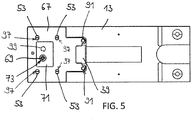
- a calibration cover 67 fastened to the weighing cell 11 by means of a fastening screw 69 is provided ( Fig. 5 ), which at least partially covers the recess 33 and thus the circuit board 39 and the two mounting screws 59 from above and thus inaccessible from the outside.
- the fastening screw 69 is screwed into a formed in the recess 33 blind hole 79 with internal thread.
- the fastening screw 69 extends through a formed in the calibration cover 67, in Fig. 5 through hole 73 concealed by the fixing screw 69, a through hole 75 formed in the circuit board 39, and a through hole 77 formed in the protective cover 49, the three through holes 73, 75, 77 being aligned with each other in the direction perpendicular to the surface of the measuring body 13.
- the presence of the fastening screw 69 can be detected by a light barrier 81 attached to the underside of the printed circuit board 39 and covered by the calibration cover 67 from the outside.
- the transmitter 83 and the receiver 85 of the light barrier 81 are on two opposite each other Side of the formed in the circuit board 39 through hole 75 arranged so that the light barrier 81 is interrupted by the screwed-in fixing screw 69.
- the light barrier 81 is designed such that a switching signal is generated when the light barrier 81 is no longer interrupted by the fastening element 69, ie when the fastening screw 69 is unscrewed.
- the switching signal of the light barrier 81 is used to cancel the above-described electronic write protection of the memory 87 with the calibration data of the load cell, as required for a permissible recalibration of the load cell 11.
- the calibration cover 67 is provided with a calibration mark 71 in the form of a transparent sticker affixed to the calibration screw 69 for the calibration cover 67, it can be determined by optical inspection when the calibration cover fixing screw 69 is removed because the calibration mark 71 then inevitably destroyed. However, if the fastening screw 69 is removed by an authorized person, the validity of the calibration still remains, which is indicated in particular by the fact that the load cell 11 is provided with a repair indicator.
- Fig. 5 how out Fig. 5 can be seen, not only the recess 33 is covered by the calibration cover 67, but it also in addition, the mounting holes 19, via which the load cell 11 can be fastened by means of screws to a fixed part of a scale, and the said screws, covered, so that Also recognizable is when this attachment was accessed.
- the calibration cover 67 two fixing holes 91 and four receiving holes 97 are formed.
- the fixing holes 91 engages a respective fixing pin 93 for the calibration cover 67, which in each case over the circuit board 39 in addition
- Direction of the calibration cover 67 protrudes from the protective cover 49, wherein the sake of clarity in Fig. 5 the fixing pins 93 are not shown.
- the printed circuit board 39 has a recess 95 in the respective area.
- In the four receiving holes 97 access four of the protective cover 49 protruding and beyond the PCB 39 Biegeschnapphaken 53 a.
- an alignment device is provided to align the protective cover 49 relative to the calibration cover 67.
- a pin 99 protruding in the direction of the protective cover 49 is provided, which in FIG Fig. 5 is not visible in itself and therefore shown in a dashed line.
- the pin 99 extends through a through hole 103 formed in the circuit board 39 and cooperates with a counter pin 101 provided on the protective cover 49 to prevent the calibration cover 67 from being pressed onto the circuit board 39 when the fixing screw 69 is tightened.
Abstract
Die vorliegende Erfindung betrifft eine Wägezelle für eine Waage mit einem monolithisch ausgebildeten Messkörper (13), der einen Kraftaufnahmeabschnitt (15), einen Krafteinleitungsabschnitt (17) und einen zwischen dem Kraftaufnahmeabschnitt (15) und dem Krafteinleitungsabschnitt (17) angeordneten Gelenkabschnitt (23) aufweist, mit zumindest einem oberseitig auf dem Gelenkabschnitt (23) angeordneten Dehnungsmessstreifen (27) zur Erfassung einer dehnenden Verformung des Messkörpers (13), und mit einer kraftaufnahmeseitig und zumindest teilweise auf einer Leiterplatte (39) angeordneten Elektronik (43) mit einem Speicher (87), in dem Kalibrierungsdaten der Wägezelle (11) und/oder ein Wert für die Erdbeschleunigung gespeichert sind, wobei eine Hardware-Schnittstelle (45) vorgesehen ist, über die auf den Speicher (87) zugreifbar ist und über die die in dem Speicher (87) gespeicherten Kalibrierungsdaten und/oder der Wert für die Erdbeschleunigung änderbar sind,
wobei ein elektronischer Schreibschutz für den Speicher (87) vorgesehen ist, wobei die Elektronik (43) eine Schalteinrichtung (81) umfasst, um den Schreibschutz des Speichers (87) zu deaktivieren, und wobei eine abnehmbare Abdeckung (67) vorgesehen ist, die mittels eines durch eine Eichmarke (71) gesicherten Befestigungselements (69), insbesondere einer Befestigungsschraube, an dem Kraftaufnahmeabschnitt (15) des Messkör pers (13) befestigt ist und die Schalteinrichtung (81) von außen unzugänglich abdeckt.

wherein an electronic write protection for the memory (87) is provided, wherein the electronics (43) comprises a switching device (81) to disable the write protection of the memory (87), and wherein a removable cover (67) is provided by means of a secured by a calibration mark (71) fastener (69), in particular a fastening screw, on the force receiving portion (15) of the Messkör pers (13) is fixed and the switching device (81) inaccessible from the outside.
Description
Die vorliegende Erfindung betrifft eine Wägezelle für eine Waage mit einem monolithisch ausgebildeten Messkörper, der einen Kraftaufnahmeabschnitt, einen Krafteinleitungsabschnitt und einen zwischen dem Kraftaufnahmeabschnitt und dem Krafteinleitungsabschnitt angeordneten Gelenkabschnitt aufweist, mit zumindest einem oberseitig auf dem Gelenkabschnitt angeordneten Dehnungsmessstreifen zur Erfassung einer dehnenden Verformung des Messkörpers, und mit einer kraftaufnahmeseitig und zumindest teilweise auf einer Leiterplatte angeordneten Elektronik mit einem Speicher, in dem Kalibrierungsdaten der Wägezelle und/oder ein Wert für die Erdbeschleunigung gespeichert sind, wobei eine Hardware-Schnittstelle vorgesehen ist, über die auf den Speicher zugreifbar ist und über die die in dem Speicher gespeicherten Kalibrierungsdaten und/oder der Wert für die Erdbeschleunigung änderbar sind. Insbesondere weist der Messkörper eine Längsachse und ein kraftaufnahmeseitiges axiales Ende und ein krafteinleitungsseitiges axiales Ende auf. Insbesondere weist die Elektronik einen Analog-Digital-Wandler zur Verarbeitung wenigstens eines Ausgangssignals des zumindest eines Dehnungsmessstreifens auf. Insbesondere ist die Elektronik mit dem zumindest einen Dehnungsmessstreifen elektrisch verbunden und/oder ist die Hardware-Schnittstelle mit der Elektronik elektrisch verbunden.The present invention relates to a weighing cell for a balance with a monolithic measuring body, which has a force receiving section, a force introduction section and a joint section arranged between the force receiving section and the force introduction section, with at least one strain gauge arranged on the upper side on the hinge section for detecting a stretching deformation of the measuring body. and with a power receiving side and at least partially arranged on a printed circuit board electronics with a memory in which calibration data of the load cell and / or a value for the acceleration of gravity are stored, wherein a hardware interface is provided, via which the memory is accessible and on the the calibration data stored in the memory and / or the value for the gravitational acceleration are changeable. In particular, the measuring body has a longitudinal axis and a force receiving side axial end and a force introduction side axial end. In particular, the electronics have an analog-to-digital converter for processing at least one output signal of the at least one strain gauge. In particular, the electronics are electrically connected to the at least one strain gauge and / or the hardware interface is electrically connected to the electronics.
Wägezellen werden vor ihrer Auslieferung im Werk erstkalibriert. Hierzu werden z.B. mittels Kalibriergewichten Messwertabweichungen der Wägezelle von dem bekannten Gewicht der Kalibriergewichte ermittelt, und anschließend wird die Elektronik der Wägezelle, insbesondere ein Messverstärker der Wägezelle, derart eingestellt bzw. abgeglichen, dass das bekannte Gewicht der Kalibriergewichte korrekt auf einer Anzeige der Waage angezeigt wird. Hierbei werden entsprechende Kalibrierungsdaten in einem Speicher der Wägezelle hinterlegt. Da das von einer Waage bestimmte Gewicht und die Kalibrierungsdaten von dem Aufstellungsort der Waage, nämlich der Höhe über dem Meeresspiegel und dem Breitengrad abhängen, kann auch der Wert der an dem Aufstellungsort der Waage herrschenden Erdbeschleunigung in dem Speicher hinterlegt werden.Load cells are first calibrated at the factory before delivery. For this purpose, for example by means of calibration weights measured value deviations of the load cell of the known weight of the calibration determined, and then the electronics of the load cell, in particular a measuring amplifier of the load cell, adjusted or adjusted so that the known weight of the calibration weights displayed correctly on a display of the scale. Here, appropriate calibration data are stored in a memory of the load cell. Since the weight determined by a balance and the calibration data depend on the location of the balance, namely the height above sea level and latitude, the value of the gravitational acceleration prevailing at the location of the balance may also be stored in the memory.
Eichpflichtige Waagen bzw. eichpflichtige Wägezellen müssen geeichet werden, d.h. einer speziellen, vom Gesetzgeber vorgeschriebenen Prüfung auf die Einhaltung zugrundeliegender eichrechtlicher Vorschriften, insbesondere Eichfehlergrenzen, unterzogen werden. Mit einer Eichmarke wird gekennzeichnet, dass eine Eichung durchgeführt wurde. Die Kalibrierungsdaten und/oder der Wert für die Erdbeschleunigung dürfen dann nicht mehr geändert werden. Hierzu wird die Eichmarke derart angebracht, dass sie zwangsläufig zerstört werden muss, wenn auf den Speicher zugegriffen werden soll, wodurch die Waage bzw. die Wägezelle ihre Eichung verliert, d.h. enteicht wird.Verifiable scales or custody transfer cells must be calibrated, i. a special, prescribed by the legislature test for compliance with underlying legal requirements, in particular calibration error limits. A calibration mark indicates that a calibration has been carried out. The calibration data and / or the value for the gravitational acceleration must then not be changed. For this purpose, the calibration mark is mounted in such a way that it must necessarily be destroyed when the memory is to be accessed, whereby the balance or the weighing cell loses its calibration, i. is deflated.
Allerdings ist es empfehlenswert, die Waage regelmäßig zu rekalibrieren, um zeitliche Drifts bzw. Langzeiteinflüsse auszugleichen, wozu auf den Speicher zugegriffen werden muss, um entsprechend geänderte Kalibrierungsdaten zu speichern. Ferner kann es erforderlich sein, auf den Speicher zuzugreifen, um den Wert für die Erdbeschleunigung zu ändern, wenn die Waage an einem anderen als dem bisherigen Ort aufgestellt wird. Eine Rekalibrierung ist dabei in der Regel nicht erforderlich, da die Kalibrierungsdaten für verschiedene Erdbeschleunigungen ineinander umgerechnet werden können. Derartige Änderungen der in dem Speicher hinterlegten Daten können von hierzu zugelassenen Personen, insbesondere staatlich zugelassenen Instandsetzern, wie z.B. Service-Techniker des Herstellers, vorgenommen werden, die die Waage bzw. die Wägezelle anschließend mit einem Instandsetzerkennzeichen versehen, so dass die Gültigkeit der Eichung weiterhin bestehen bleibt.However, it is recommended to recalibrate the balance regularly to compensate for time drifts or long-term effects, which requires accessing the memory to store appropriately modified calibration data. Furthermore, it may be necessary to access the memory to change the acceleration value when the balance is placed at a different location than the previous location. A recalibration is usually not required because the calibration data for different accelerations can be converted into each other. Such changes in the data stored in the memory can be made by persons authorized for this purpose, in particular state-approved repairers, such as service technicians of the manufacturer, who then provide the scale or the load cell with a repair indicator, so that the validity of the calibration continues persists.
Aus dem Stand der Technik ist es bekannt, für den Zugriff auf den Speicher eine auf einer der Leiterplatte angeordnete Hardware-Schnittstelle, über die auf den Speicher zugegriffen werden kann, vorzusehen. Ferner ist ein Metallbügel vorgesehen, der mit einem Ende mittels einer Befestigungsschraube an dem Gehäuse der Waage befestigt ist und sich mit seinem freien Ende zu der Wägezelle erstreckt, um zumindest die Hardware-Schnittstelle der Leiterplatte von außen unzugänglich abzudecken. Die Befestigungsschraube ist dabei durch eine Eichmarke gesichert.From the prior art it is known to provide for accessing the memory arranged on one of the circuit board hardware interface through which the memory can be accessed. Further, a metal bracket is provided, which is fastened with one end by means of a fastening screw to the housing of the balance and extends with its free end to the load cell to cover at least the hardware interface of the circuit board from the outside inaccessible. The fixing screw is secured by a calibration mark.
Eine derartige Abdeckung für die dem Speicher zugeordnete Hardware-Schnittstelle ist jedoch vergleichsweise massiv und sperrig.However, such coverage for the hardware interface associated with the memory is relatively massive and cumbersome.
Der Erfindung liegt die Aufgabe zugrunde, eine handlichere Möglichkeit anzugeben, den Speicher der Wägezelle der eingangs genannten Art vor einer unzulässigen Manipulation zu schützen, wobei zulässige Änderungen auch weiterhin möglich sein sollen.The invention has for its object to provide a handy way to protect the memory of the load cell of the type mentioned above from improper manipulation, with permissible changes should continue to be possible.
Diese Aufgabe wird durch eine Wägezelle mit den Merkmalen des Anspruchs 1 gelöst, und insbesondere dadurch, dass ein elektronischer Schreibschutz für den Speicher vorgesehen ist, wobei die Elektronik eine, insbesondere auf der Leiterplatte angeordnete, Schalteinrichtung umfasst, um den Schreibschutz des Speichers zu deaktivieren, und wobei eine abnehmbare Abdeckung, insbesondere Eichabdeckung und/oder Abdeckplatte, vorgesehen ist, die mittels eines durch eine Eichmarke gesicherten Befestigungselements, insbesondere einer Befestigungsschraube, insbesondere oberseitig, an dem Kraftaufnahmeabschnitt des Messkörpers befestigt ist und die Schalteinrichtung von außen unzugänglich abdeckt.This object is achieved by a load cell with the features of claim 1, and in particular by the fact that an electronic write protection for the memory is provided, the electronics comprising a, in particular arranged on the circuit board, switching device to disable the write protection of the memory, and wherein a removable cover, in particular calibration cover and / or cover plate, is provided which is secured by means of a secured by a calibration mark fastener, in particular a fastening screw, in particular on the upper side, to the force receiving portion of the measuring body and the switching device inaccessible from the outside.
Somit ist eine Abdeckung für die dem Speicher zugeordnete, insbesondere auf der Leiterplatte angeordnete, Hardware-Schnittstelle überhaupt nicht erforderlich, um den Speicher vor einer unzulässigen Manipulation zu schützen. Vielmehr kann die Hardware-Schnittstelle von außerhalb der Wägezelle frei zugänglich sein. Erfindungsgemäß erfolgt der Schutz des Speichers vor einer unzulässigen Manipulation dadurch, dass der Speicher elektronisch schreibgeschützt ist und der Schreibschutz, insbesondere nur, durch eine Schalteinrichtung aufhebbar ist, die durch eine durch eine Eichmarke gesicherte Abdeckung von außen unzugänglich abgedeckt ist. Darüber hinaus ist die Abdeckung nicht an dem Gehäuse der Waage befestigt, sondern an der Wägezelle selbst. Insbesondere können auch weiterhin Änderungen an den in dem Speicher hinterlegten, insbesondere eichrelevanten Daten, die auch über die vorstehend genannten Daten in Form der Kalibrierungsdaten und/oder des Wert für die Erdbeschleunigung hinausgehende Daten umfassen können, durch Deaktivieren des Schreibschutzes durch eine hierfür zugelassene Person vorgenommen werden.Thus, a cover for the memory associated with the, in particular arranged on the circuit board, hardware interface is not at all necessary to protect the memory from inadmissible manipulation. Rather, the hardware interface can be freely accessible from outside the load cell. According to the memory of the memory is protected against inadmissible manipulation in that the memory is electronically write-protected and the write protection, in particular only, can be canceled by a switching device, which is covered by a secured by a calibration mark cover from the outside inaccessible. In addition, the cover is not attached to the housing of the balance, but at the load cell itself. In particular, changes to the stored in the memory, in particular calibration-relevant data, which also on the above data in the form of calibration data and / or the Value for gravitational acceleration may be made by deactivating the write protection by a person authorized to do so.
Bevorzugt handelt es sich bei der Schalteinrichtung um einen Sensor. Durch einen Sensor kann der Schreibschutz automatisch deaktiviert werden.The switching device is preferably a sensor. With a sensor the write protection can be deactivated automatically.
Vorzugsweise ist der Sensor dazu ausgebildet, ein Entfernen des Befestigungselements aus seiner befestigten Stellung, insbesondere ein Herausschrauben der Befestigungsschraube, zu erfassen und, insbesondere nur, nach Erfassen eines Entfernens des Befestigungselements ein Schaltsignal auszugeben, um den Schreibschutz des Speichers zu deaktivieren. Solange sich das Befestigungsmittel in seiner befestigten Stellung befindet, ist der Speicher mit den Kalibrierungsdaten und/oder dem Wert für die Erdbeschleunigung schreibgeschützt.The sensor is preferably designed to detect a removal of the fastening element from its fastened position, in particular a unscrewing of the fastening screw, and, in particular, to output a switching signal after detecting a removal of the fastening element in order to deactivate the write protection of the memory. As long as the fastener is in its fastened position, the memory is write protected with the calibration data and / or gravitational acceleration value.
Nach einer bevorzugten Ausführungsform der Erfindung ist der Sensor eine Lichtschranke mit einem Sender und einem Empfänger, die derart angeordnet ist, dass der Strahlengang und/oder der Lichtstrahl zwischen dem Sender und dem Empfänger unterbrochen ist, wenn sich das Befestigungselement, insbesondere die Befestigungsschraube für die Abdeckung, in seiner befestigten Stellung befindet, und die dazu ausgebildet ist, ein Schaltsignal auszugeben, um den Schreibschutz des Speichers zu deaktivieren, wenn der Strahlengang zwischen dem Sender und dem Empfänger nicht mehr durch das Befestigungselement unterbrochen ist. Wird das Befestigungselement entfernt und entsprechend ein Schaltsignal ausgegeben, kann in der Waage, insbesondere der Wägezelle, insbesondere dem genannten Speicher, gespeichert werden, dass die Waage bzw. die Wägezelle enteicht wurde. Die Waage bzw. die Wägezelle ist dann nicht mehr geeichet, selbst wenn das Befestigungselement später wieder in seine befestigte Stellung zurückverbracht wird, so dass die Lichtschranke wieder unterbrochen ist. Ein derartiger Sensor besitzt auch den Vorteil, dass ein unter Umständen auch manipulativ herbeigeführter Sensordefekt, bei dem kein Licht mehr durch den Sender ausgestrahlt wird, nicht zu einem versehentlichen Freigeben des Schreibschutzes führt.According to a preferred embodiment of the invention, the sensor is a light barrier with a transmitter and a receiver, which is arranged such that the beam path and / or the light beam between the transmitter and the receiver is interrupted when the fastener, in particular the fastening screw for the cover, is in its fastened position, and which is adapted to output a switching signal to disable the write protection of the memory when the beam path between the transmitter and the receiver is no longer is interrupted by the fastener. If the fastening element is removed and a switching signal correspondingly output, it is possible to store in the balance, in particular the weighing cell, in particular the named memory, that the balance or the weighing cell has been deflated. The scale or the load cell is then no longer calibrated, even if the fastener is later returned to its fastened position, so that the light barrier is interrupted again. Such a sensor also has the advantage that a possibly also manipulatively brought about sensor defect, in which no more light is emitted by the transmitter, does not lead to an accidental release of the write protection.
Insbesondere kann eine Blende vorgesehen sein, hinter der die Lichtschranke angeordnet ist, um von außen einfallendes Licht von der Lichtschranke fernzuhalten. Hierdurch kann verhindert werden, dass ein Schaltsignal der Lichtschranke durch manipulatives Einstrahlen von Licht auf den Empfänger der Lichtschranke ausgelöst wird, obwohl sich das Befestigungselement, insbesondere die Befestigungsschraube für die Abdeckung, weiterhin in seiner befestigten Stellung befindet.In particular, a diaphragm can be provided, behind which the light barrier is arranged, in order to keep light falling in from the outside from the light barrier. In this way it can be prevented that a switching signal of the light barrier is triggered by manipulative irradiation of light onto the receiver of the light barrier, although the fastening element, in particular the fastening screw for the cover, is still in its fastened position.
Alternativ kann die Schalteinrichtung auch ein manuell betätigbarer Schalter bzw. ein manuell betätigtes elektrisches Bauelement sein. Ist der Schalter auf der Unterseite der Leiterplatte montiert, wobei die Abdeckung die Leiterplatte von oben abdeckt, muss der Schalter durch eine Öffnung in der Leiterplatte bedient werden. Beispielsweise werden das Befestigungselement und die Abdeckung entfernt, und anschließend wird mittels eines Schraubenziehers durch die Öffnung in der Leiterplatte hindurch der Schalter betätigt. Es kann in diesem Zusammenhang vorgesehen sein, dass die Eichabdeckung im Bereich des Befestigungselements mit einer Klappe versehen ist, die nur geöffnet werden kann, wenn das Befestigungselement entfernt ist, so dass der Schalter besser zugänglich ist.Alternatively, the switching device may also be a manually operable switch or a manually operated electrical component. If the switch is mounted on the underside of the circuit board, with the cover covering the circuit board from above, the switch must be operated through an opening in the circuit board. For example, the fastener and the cover are removed, and then the switch is actuated by means of a screwdriver through the opening in the circuit board. It may be provided in this context that the calibration cover in the region of the fastener with a Flap is provided, which can only be opened when the fastener is removed, so that the switch is more accessible.
Die Abdeckung kann aus Kunststoff gefertigt sein. Die Abdeckung kann als eine Abdeckplatte ausgebildet sein. Die Eichmarke kann, insbesondere in Europa, ein Aufkleber oder, insbesondere in den USA, eine Eichplombe sein.The cover can be made of plastic. The cover may be formed as a cover plate. The calibration mark may, in particular in Europe, be a sticker or, in particular in the USA, a calibration seal.
Vorzugsweise ist die Befestigungsschraube in ein, insbesondere oberseitig, in dem Kraftaufnahmeabschnitt ausgebildetes Loch mit Innengewinde, insbesondere ein Sackloch, eingeschraubt, wobei sich die Befestigungsschraube durch ein in der Abdeckung vorgesehenes Durchgangsloch und ein korrespondierendes, in der Leiterplatte vorgesehenes Durchgangsloch und gegebenenfalls ein korrespondierendes, in einer Schutzabdeckung vorgesehenes Durchgangsloch hindurch erstreckt. Insbesondere kann das Loch in einer, insbesondere oberseitig, in dem Kraftaufnahmeabschnitt vorgesehenen Vertiefung ausgebildet sein.Preferably, the fastening screw in a, in particular the upper side, formed in the force receiving portion hole with internal thread, in particular a blind hole, screwed, wherein the fastening screw provided by a cover provided in the through hole and a corresponding, provided in the circuit board through hole and optionally a corresponding, in a protective cover provided through hole extends therethrough. In particular, the hole may be formed in a recess, in particular on the upper side, provided in the force receiving section.
Der Kraftaufnahmeabschnitt kann oberseitig eine, insbesondere dreiseitig begrenzte, Vertiefung aufweisen, die, insbesondere ausschließlich, zu einem kraftaufnahmeseitigen Ende des Messkörpers hin offen ist, in die die Leiterplatte horizontal eingesetzt ist und die durch die Abdeckung von oben abdeckt ist. Aufgrund der Anordnung der Leiterplatte auf der Oberseite des Kraftaufnahmeabschnitts kann die Höhe des Messkörpers und damit die Bauhöhe der Wägezelle unabhängig von den Abmessungen der Leiterplatte gewählt werden. Der Umstand, dass die Leiterplatte in eine Vertiefung eingesetzt ist, trägt zusätzlich dazu bei, dass die Bauhöhe der Wägezelle klein gehalten werden kann. Dies gilt insbesondere dann, wenn die Leiterplatte in der Vertiefung vollständig versenkt angeordnet ist.The force receiving portion may have on the upper side, in particular three-sided limited, recess, which is open, in particular exclusively, to a force receiving side end of the measuring body, in which the circuit board is inserted horizontally and which is covered by the cover from above. Due to the arrangement of the circuit board on the top of the force receiving portion, the height of the measuring body and thus the height of the load cell can be selected independently of the dimensions of the circuit board. The fact that the printed circuit board is inserted into a recess also contributes to the fact that the height of the load cell can be kept small. This is especially true when the circuit board is arranged completely sunk in the recess.
Vorzugsweise ist die Hardware-Schnittstelle auf der einem kraftaufnahmeseitigen Ende des Messkörpers zugewandten Seite der Leiterplatte angeordnet und/oder von außerhalb der Wägezelle frei zugänglich, wobei bevorzugt die Hardware-Schnittstelle über das kraftaufnahmeseitige Ende des Messkörpers nach außen hervorsteht und/oder als Teil einer Steckverbindung ausgebildet ist, dessen Steckrichtung horizontal, insbesondere entlang einer Längsachse des Messkörpers verläuft. Durch das Vorstehen der Hardware-Schnittstelle über das kraftaufnahmeseitige Ende des Messkörpers kann die Hardware-Schnittstelle einfach kontaktiert werden. Dies gilt insbesondere dann, wenn es sich bei der jeweiligen Steckverbindung um eine einrastende Steckverbindung handelt, die das Drücken einer Lasche erfordert, um die Steckverbindung wieder zu lösen. Neben der dem Speicher zugeordneten Hardware-Schnittstelle, die beispielsweise als USB-Schnittstelle ausgebildet sein kann, kann eine weitere Hardware-Schnittstelle vorgesehen sein, beispielsweise eine USB-Schnittstelle, die dazu ausgebildet ist, die Leiterplatte mit einem CPU-Board der Waage zu verbinden, welches dazu ausgebildet ist,, die von der Elektronik bereitgestellten Signale, insbesondere Gewichtswertsignale, zu verarbeiten.The hardware interface is preferably arranged on the side of the printed circuit board facing the force-receiving-side end of the measuring body and / or freely accessible from outside the weighing cell, the hardware interface preferably being preferred projects outward beyond the force-receiving-side end of the measuring body and / or is formed as part of a plug connection whose plug-in direction extends horizontally, in particular along a longitudinal axis of the measuring body. By protruding the hardware interface via the force-receiving end of the measuring body, the hardware interface can be contacted easily. This is especially true when it is the respective connector is a snap-in connector that requires pressing a tab to release the connector again. In addition to the memory associated with the hardware interface, which may be formed, for example, as a USB interface, a further hardware interface may be provided, such as a USB interface, which is adapted to connect the circuit board with a CPU board of the scale which is designed to process the signals provided by the electronics, in particular weight value signals.
Es kann eine Schutzabdeckung für die Leiterplatte, insbesondere für eine bestückte Seite der Leiterplatte, vorgesehen sein, wobei die Leiterplatte mit der Schutzabdeckung zu einem Modul zusammengesetzt ist, das, insbesondere mit der bestückten Seite der Leiterplatte und/oder der Schutzabdeckung nach unten, in die Vertiefung eingesetzt ist. Durch die Schutzabdeckung kann die auf der Leiterplatte angeordnete Elektronik, insbesondere der Speicher und/oder ein Analog-Digital-Wandler, gut vor Beschädigung geschützt werden.There may be a protective cover for the printed circuit board, in particular for a populated side of the printed circuit board, is provided, wherein the printed circuit board with the protective cover is assembled into a module which, in particular with the populated side of the printed circuit board and / or the protective cover down into the Well is inserted. Due to the protective cover arranged on the circuit board electronics, in particular the memory and / or an analog-to-digital converter, are well protected against damage.
Bevorzugt ist es, wenn die Schutzabdeckung wenigstens einen in Richtung der Leiterplatte über diese hinaus abstehenden Fixierzapfen und die Abdeckung wenigstens ein Fixierloch zur Aufnahme des jeweiligen von einer Schutzabdeckung abstehenden Fixierzapfens aufweist, wobei bevorzugt die Leiterplatte im Bereich des jeweiligen Fixierzapfens eine Aussparung aufweist. Hierdurch kann die Abdeckung relativ zu der Schutzabdeckung bzw. der Leiterplatte ausgerichtet werden.It is preferred if the protective cover has at least one fixing pin protruding beyond the printed circuit board in the direction of the printed circuit board and the cover has at least one fixing hole for receiving the respective fixing pin protruding from a protective cover, the printed circuit board preferably having a recess in the region of the respective fixing pin. As a result, the cover can be aligned relative to the protective cover or the printed circuit board.
Die Leiterplatte und die Schutzabdeckung können über eine insbesondere lösbare Clipverbindung mechanisch miteinander verbunden sein. Hierdurch kann eine einfache und insbesondere lösbare Verbindung geschaffen werden. Bevorzugt weist die Schutzabdeckung mehrere in Richtung der Leiterplatte, insbesondere über diese hinaus, abstehende Biegeschnapphaken auf, die die Leiterplatte im zusammengesetzten Zustand formschlüssig hintergreifen, um die Clipverbindung zu bilden.The circuit board and the protective cover can be mechanically connected to each other via a particular releasable clip connection. As a result, a simple and in particular releasable connection can be created. Preferably, the protective cover has a plurality of in the direction of the printed circuit board, in particular beyond this, projecting Biegeschnphphangen, which engage behind the circuit board in the assembled state form fit to form the clip connection.
Bevorzugt weist die Abdeckung Aufnahmelöcher zur Aufnahme der von der Schutzabdeckung abstehenden, über die Leiterplatte hinausstehenden Biegeschnapphaken auf. Der Umstand, dass sich die Biegeschnapphaken durch die Abdeckung hindurch erstrecken können, trägt dazu bei, dass die Bauhöhe der Wägezelle klein gehalten werden kann. Darüber hinaus kann hierdurch auch eine Ausrichtung der Abdeckung relativ zu der Schutzabdeckung erreicht werden.Preferably, the cover has receiving holes for receiving the projecting from the protective cover, beyond the circuit board protruding bending snap hook. The fact that the bending snap hooks can extend through the cover contributes to keeping the height of the load cell small. In addition, this can also be achieved an orientation of the cover relative to the protective cover.
Darüber hinaus kann die Abdeckung einen in Richtung der Leiterplatte abstehenden Stift aufweisen, der sich durch eine in der Leitplatte vorgesehene Durchgangsöffnung hindurch erstreckt und sich auf der Schutzabdeckung, insbesondere einem Gegenstift der Schutzabdeckung, abstützt, um die Abdeckung auf Abstand zu der Leiterplatte zu halten.In addition, the cover may have a protruding toward the circuit board pin which extends through a provided in the guide plate through opening and on the protective cover, in particular a counter pin of the protective cover is supported to keep the cover at a distance from the circuit board.
Nach einer bevorzugten Ausführungsform der Erfindung weist der Kraftaufnahmeabschnitt wenigstens ein Befestigungsloch für ein jeweiliges Befestigungsmittel, insbesondere eine jeweilige Schraube, zur Befestigung der Wägezelle an einer Waage auf, wobei die Abdeckung gleichzeitig auch das jeweilige Befestigungsloch und/oder das jeweilige Befestigungsmittel abdeckt, da auch das jeweilige Befestigungsloch und/oder das jeweilige Befestigungsmittel bei einer geeichten Waage grundsätzlich eichrelevant sind. Insbesondere kann der Kraftaufnahmeabschnitt mehrere Befestigungslöcher zur Befestigung der Wägezelle an einer Waage aufweisen, die bezüglich der Längsachse des Messkörpers beidseitig der Vertiefung und/oder beidseitig der Leiterplatte angeordnet sind.According to a preferred embodiment of the invention, the force receiving portion has at least one attachment hole for a respective attachment means, in particular a respective screw for attaching the load cell to a scale, wherein the cover simultaneously covers the respective attachment hole and / or the respective attachment means, as well respective mounting hole and / or the respective fastener in a calibrated balance are basically relevant to the custody. In particular, the force receiving portion may have a plurality of fastening holes for fastening the weighing cell to a balance, which are arranged with respect to the longitudinal axis of the measuring body on both sides of the recess and / or on both sides of the circuit board.
Die vorliegende Erfindung betrifft ferner eine Waage mit einer Wägezelle, wie sie vorstehend beschrieben ist.The present invention further relates to a balance with a load cell, as described above.
Weitere vorteilhafte Ausgestaltungen der Erfindung sind in den Ansprüchen, der Figurenbeschreibung und der Zeichnung beschrieben.Further advantageous embodiments of the invention are described in the claims, the description of the figures and the drawings.
Die Erfindung wird im Folgenden beispielhaft unter Bezugnahme auf die Zeichnung beschrieben. Es zeigen,
- Fig. 1
- eine perspektivische Ansicht einer erfindungsgemäßen Wägezelle ohne eingesetzte Leiterplatte,
- Fig. 2
- die Wägezelle aus
Fig. 1 mit eingesetzter Leiterplatte, - Fig. 3
- die Leiterplatte aus
Fig. 2 in einer Ansicht von unten, - Fig. 4
- eine perspektivische Ansicht einer Schutzabdeckung für die Leiterplatte, und
- Fig. 5
- eine Draufsicht auf die Wägezelle gemäß den
Fig. 1 und2 mit einer Eichabdeckung.
- Fig. 1
- a perspective view of a load cell according to the invention without a printed circuit board,
- Fig. 2
- the load cell off
Fig. 1 with inserted circuit board, - Fig. 3
- the circuit board off
Fig. 2 in a view from below, - Fig. 4
- a perspective view of a protective cover for the circuit board, and
- Fig. 5
- a plan view of the load cell according to the
Fig. 1 and2 with a calibration cover.
In
Oberhalb des Durchgangs 25 sind an der Außenseite des Messkörpers 13 mehrere lediglich schematisch dargestellte Dehnungsmessstreifen (DMS) 27 angeordnet, die eine Verformung des Messkörpers 13 im Bereich des Gelenkabschnitts 23 in an sich bekannter Weise detektieren. Bei der Wägezelle 11 handelt es sich daher um eine DMS-Wägezelle. Eine Last auf dem Krafteinleitungsabschnitt 17 führt zu einer hierzu proportionalen Auslenkung bzw. Verbiegung des Messkörpers 13, so dass aus der Auslenkung bzw. einer Dehnung des Messkörpers 13 das Gewicht der Last ermittelt werden kann.Above the
In dem Kraftaufnahmeabschnitt 15 ist an der Oberseite eine rechteckförmige Vertiefung 33 ausgebildet, die durch zwei sich in Richtung der Längsachse L des Messkörpers 13 erstreckende, bezüglich der Längsachse L gegenüberliegende Längsseitenwände 35 sowie durch eine dem krafteinleitungsseitigen Ende 31 zugewandte Stirnseitenwand 37 begrenzt ist. Zu dem kraftaufnahmeseitigen Ende 29 des Messkörpers 13 hin ist die Vertiefung 33 offen. Die Vertiefung 33 ist dabei bezüglich der Längsachse L mittig zwischen zwei Befestigungslöchern 19 zu ihrer einen Längsseite und zwei Befestigungslöchern 19 zu ihrer anderen Längsseite angeordnet.In the
In die Vertiefung 33 ist eine Leiterplatte 39 horizontal eingesetzt, wie in
Die Leiterplatte 39 ist lediglich einseitig bestückt, so dass die Leiterplatte 39 eine Bestückungsseite, die in
Durch die Anordnung der Leiterplatte 39 in der Vertiefung 33 auf der Oberseite des Messkörpers 13 kann eine Wägezelle 11 mit geringer Bauhöhe realisiert werden.By arranging the
Die Leiterplatte 39 weist an ihrer dem kraftaufnahmeseitigen Ende 29 des Messkörpers 13 zugewandten Seite zwei mit der Elektronik 43 elektrisch verbundene Hardware-Schnittstellen 45, 47 auf, die jeweils als Buchse einer Steckverbindung ausgebildet sind und von außerhalb der Wägezelle 11 frei zugänglich sind, so dass die jeweiligen zugehörigen Stecker entlang der Längsachse L des Messkörpers 13 in die Buchsen 45, 47 eingesteckt oder aus diesen gelöst werden können. Bei der Hardware-Schnittstelle 45 handelt es sich um eine serielle Schnittstelle, über die während der Herstellung der Wägezelle 11 ein Abgleichen der Wägezelle 11 möglich ist. Insbesondere werden hierbei Kalibrierungsdaten der Wägezelle 11 in einem eichfähigen Speicher 87 der Elektronik 43 gespeichert, wobei anschließend ein elektronischer Schreibschutz aktiviert wird, um eine spätere unerlaubte Manipulation der Kalibrierungsdaten zu verhindern. Bei der Hardware-Schnittstelle 47 handelt es sich um eine USB-Schnittstelle, über die der von der Elektronik 43 berechnete Gewichtswert von einem nicht dargestellten, Wägezellen-externen CPU-Board ausgelesen bzw. an dieses ausgegeben werden kann.The printed
Wie aus
Zum Schutz der Elektronik 43 ist eine Schutzabdeckung 49 vorgesehen, die in
An ihrer dem kraftaufnahmeseitigen Ende 29 des Messkörpers 13 zugewandten Stirnseite hingegen ist die Schutzabdeckung 49 stegfrei, da dort die beiden Hardware-Schnittstellen 45, 47 angeordnet sind, die von außen zugänglich sind, wie vorstehend erläutert ist.On the other hand, the
Die Leiterplatte 39 weist zwei Durchgangslöcher 57 auf (
Darüber hinaus ist eine mittels einer Befestigungsschraube 69 an der Wägezelle 11 befestigte Eichabdeckung 67 vorgesehen (
Die Befestigungsschraube 69 ist in einem in der Vertiefung 33 ausgebildeten Sackloch 79 mit Innengewinde eingeschraubt. Hierzu erstreckt sich die Befestigungsschraube 69 durch ein in der Eichabdeckung 67 ausgebildetes, in
Die Anwesenheit der Befestigungsschraube 69 kann von einer an der Unterseite der Leiterplatte 39 angebrachten, von der Eichabdeckung 67 von außen unzugänglich abgedeckten Lichtschranke 81 erkannt werden. Hierzu sind der Sender 83 und der Empfänger 85 der Lichtschranke 81 auf zwei aneinander gegenüberliegenden Seiten des in der Leiterplatte 39 ausgebildeten Durchgangslochs 75 angeordnet, so dass durch die eingeschraubte Befestigungsschraube 69 die Lichtschranke 81 unterbrochen wird. Die Lichtschranke 81 ist derart ausgebildet, dass ein Schaltsignal erzeugt wird, wenn die Lichtschranke 81 nicht mehr durch das Befestigungselement 69 unterbrochen ist, d.h. wenn die Befestigungsschraube 69 herausgeschraubt wird.The presence of the
Das Schaltsignal der Lichtschranke 81 wird dafür verwendet, den vorstehend erläuterten elektronischen Schreibschutz des Speichers 87 mit den Kalibrierungsdaten der Wägezelle aufzuheben, wie es für eine zulässige Rekalibrierung der Wägezelle 11 erforderlich ist.The switching signal of the light barrier 81 is used to cancel the above-described electronic write protection of the
Da die Eichabdeckung 67 mit einer Eichmarke 71 in Form eines transparent dargestellten Aufklebers versehen ist, der auf die Befestigungsschraube 69 für die Eichabdeckung 67 aufgeklebt ist, kann durch optische Prüfung festgestellt werden, wenn die Befestigungsschraube 69 für die Eichabdeckung 67 entfernt wird, da die Eichmarke 71 dann zwangsläufig zerstört wird. Wird die Befestigungsschraube 69 durch eine zugelassene Person entfernt, bleibt die Gültigkeit der Eichung jedoch weiterhin bestehen, was insbesondere dadurch kenntlich gemacht wird, dass die Wägezelle 11 mit einem Instandsetzerkennzeichen versehen wird.Since the
Wie aus
Darüber hinaus sind in der Eichabdeckung 67 zwei Fixierlöcher 91 und vier Aufnahmelöcher 97 ausgebildet. In die Fixierlöcher 91 greift ein jeweiliger Fixierzapfen 93 für die Eichabdeckung 67 ein, der jeweils über die Leiterplatte 39 hinaus in Richtung der Eichabdeckung 67 von der Schutzabdeckung 49 absteht, wobei der Übersichtlichkeit halber in
Schließlich ist eine Ausrichteinrichtung vorgesehen, um die Schutzabdeckung 49 relativ zu der Eichabdeckung 67 auszurichten. Hierzu ist an der Unterseite der Eichabdeckung 67 ein in Richtung der Schutzabdeckung 49 abstehender Stift 99 der vorgesehen, der in
- 1111
- Wägezelleload cell
- 1313
- Messkörpermeasuring body
- 1515
- KraftaufnahmeabschnittForce receiving portion
- 1717
- KrafteinleitungsabschnittForce application section
- 1919
- Befestigungslochmounting hole
- 2121
- Befestigungslochmounting hole
- 2323
- Gelenkabschnitthinge section
- 2525
- Durchgangpassage
- 2727
- DehnungsmessstreifenStrain gauges
- 2929
- EndeThe End
- 3131
- EndeThe End
- 3333
- Vertiefungdeepening
- 3535
- LängsseitenwandLongitudinal side wall
- 3737
- StirnseitenwandEnd wall
- 3939
- Leiterplattecircuit board
- 4141
- Rillegroove
- 4343
- Elektronikelectronics
- 4545
- Hardware-SchnittstelleHardware interface
- 4747
- Hardware-SchnittstelleHardware interface
- 4949
- Schutzabdeckungprotective cover
- 5151
- Clipverbindungclip connection
- 5353
- BiegeschnapphakenBending snap hooks
- 5555
- Stegweb
- 5757
- DurchgangslochThrough Hole
- 5959
- Befestigungsschraubefixing screw
- 6161
- Sacklochblind
- 6363
- Abstandhülsespacer
- 6565
- Aussparungrecess
- 6767
- EichabdeckungEich cover
- 6969
- Befestigungsschraubefixing screw
- 7171
- Eichmarkecalibration mark
- 7373
- DurchgangslochThrough Hole
- 7575
- DurchgangslochThrough Hole
- 7777
- DurchgangslochThrough Hole
- 7979
- Sacklochblind
- 8181
- Lichtschrankephotocell
- 8383
- Sendertransmitter
- 8585
- Empfängerreceiver
- 8787
- SpeicherStorage
- 8989
- Analog-Digital-WandlerAnalog to digital converter
- 9191
- Fixierlochfixing hole
- 9393
- Fixierzapfenfixing pins
- 9595
- Aussparungrecess
- 9797
- Aufnahmelochreceiving hole
- 9999
- Stiftpen
- 101101
- Gegenstiftto pin
- 103103
- DurchgangsöffnungThrough opening
- LL
- Längsachselongitudinal axis
Claims (15)
dass ein elektronischer Schreibschutz für den Speicher (87) vorgesehen ist, wobei die Elektronik (43) eine Schalteinrichtung (81) umfasst, um den Schreibschutz des Speichers (87) zu deaktivieren, und wobei eine abnehmbare Abdeckung (67) vorgesehen ist, die mittels eines durch eine Eichmarke (71) gesicherten Befestigungselements (69), insbesondere einer Befestigungsschraube, an dem Kraftaufnahmeabschnitt (15) des Messkörpers (13) befestigt ist und die Schalteinrichtung (81) von außen unzugänglich abdeckt.Load cell for a balance
in that an electronic write protection is provided for the memory (87), the electronics (43) comprising a switching device (81) for deactivating the write protection of the memory (87), and a removable cover (67) being provided by means of a secured by a calibration mark (71) fastener (69), in particular a fastening screw, on the force receiving portion (15) of the measuring body (13) is attached and the switching device (81) inaccessible from the outside.
dadurch gekennzeichnet,
dass es sich bei der Schalteinrichtung (81) um einen Sensor oder einen manuell betätigbaren Schalter handelt.Load cell according to claim 1,
characterized,
in that the switching device (81) is a sensor or a manually operable switch.
dadurch gekennzeichnet,
dass der Sensor (81) dazu ausgebildet ist, ein Entfernen des Befestigungselements (69) aus seiner befestigten Stellung, insbesondere ein Herausschrauben der Befestigungsschraube, zu erfassen und nach Erfassen eines Entfernens des Befestigungselements (69) ein Schaltsignal auszugeben, um den Schreibschutz des Speichers (87) zu deaktivieren.Load cell according to claim 2,
characterized,
in that the sensor (81) is designed to detect a removal of the fastening element (69) from its fastened position, in particular unscrewing the fastening screw, and to output a switching signal after detection of removal of the fastening element (69) in order to protect the memory ( 87).
dadurch gekennzeichnet,
dass der Sensor (81) eine Lichtschranke mit einem Sender (83) und einem Empfänger (85) ist, die derart angeordnet ist, dass der Strahlengang zwischen dem Sender (83) und dem Empfänger (85) unterbrochen ist, wenn sich das Befestigungselement (69) in seiner befestigten Stellung befindet, und die dazu ausgebildet ist, ein Schaltsignal auszugeben, um den Schreibschutz des Speichers (87) zu deaktivieren, wenn der Strahlengang zwischen dem Sender (83) und dem Empfänger (85) nicht mehr durch das Befestigungselement (69) unterbrochen ist.Load cell according to claim 3,
characterized,
in that the sensor (81) is a light barrier with a transmitter (83) and a receiver (85) arranged such that the beam path between the transmitter (83) and the receiver (85) is interrupted when the fastening element ( 69) is in its fastened position and which is adapted to output a switching signal to deactivate the write protection of the memory (87) when the beam path between the transmitter (83) and the receiver (85) is no longer blocked by the fastening element (85). 69) is interrupted.
dadurch gekennzeichnet,
dass eine Blende vorgesehen ist, hinter der die Lichtschranke (81) angeordnet ist, um von außen einfallendes Licht von der Lichtschranke (81) fernzuhalten.Load cell according to claim 4,
characterized,
that a diaphragm is provided behind the located the light barrier (81) is to keep outside incident light from the light barrier (81).
dadurch gekennzeichnet,
dass die Befestigungsschraube (69) in ein in dem Kraftaufnahmeabschnitt (15) ausgebildetes Loch (79) mit Innengewinde, insbesondere ein Sackloch, eingeschraubt, wobei sich die Befestigungsschraube (69) durch ein in der Abdeckung (67) vorgesehenes Durchgangsloch (73) und ein korrespondierendes, in der Leiterplatte (39) vorgesehenes Durchgangsloch (75) und gegebenenfalls ein korrespondierendes, in einer Schutzabdeckung (49) vorgesehenes Durchgangsloch (77) hindurch erstreckt.Load cell according to at least one of the preceding claims,
characterized,
in that the fastening screw (69) is screwed into an internally threaded hole (79) in the force receiving section (15), in particular a blind hole, the fastening screw (69) being formed by a through hole (73) provided in the cover (67) and a corresponding, in the circuit board (39) provided through hole (75) and optionally a corresponding, in a protective cover (49) provided through hole (77) extends therethrough.
dadurch gekennzeichnet,
dass der Kraftaufnahmeabschnitt (15) oberseitig eine Vertiefung (33) aufweist, die zu einem kraftaufnahmeseitigen Ende (29) des Messkörpers (13) hin offen ist, in die die Leiterplatte (39) horizontal eingesetzt ist und die durch die Abdeckung (67) von oben abdeckt ist, wobei bevorzugt die Leiterplatte (39) in der Vertiefung (33) vollständig versenkt angeordnet ist.Load cell according to at least one of the preceding claims,
characterized,
that the force receiving portion (15) on the upper side a recess (33) which is open to a force receiving side end (29) of the measuring body (13), in which the circuit board (39) is inserted horizontally and by the cover (67) of is covered above, wherein preferably the circuit board (39) in the recess (33) is arranged completely sunk.
dadurch gekennzeichnet,
dass die Hardware-Schnittstelle (45) auf der einem kraftaufnahmeseitigen Ende (29) des Messkörpers (13) zugewandten Seite der Leiterplatte (39) angeordnet ist und/oder von außerhalb der Wägezelle (11) frei zugänglich ist, wobei bevorzugt die Hardware-Schnittstelle (45) über das kraftaufnahmeseitige Ende (29) des Messkörpers (13) nach außen hervorsteht und/oder als Teil einer Steckverbindung ausgebildet ist, dessen Steckrichtung horizontal, insbesondere entlang einer Längsachse (L) des Messkörpers (13) verläuft.Load cell according to at least one of the preceding claims,
characterized,
that the hardware interface (45) is arranged on a force-receiving end (29) of the measuring body (13) facing side of the printed circuit board (39) and / or is freely accessible from outside the load cell (11), wherein preferably the hardware interface (45) projects outwardly beyond the force-receiving-side end (29) of the measuring body (13) and / or is formed as part of a plug connection whose plugging direction is horizontal, in particular along a longitudinal axis (L) of the measuring body (13) runs.
dadurch gekennzeichnet,
dass eine Schutzabdeckung (49) für die Leiterplatte (39), insbesondere für eine bestückte Seite der Leiterplatte (39), vorgesehen ist, wobei die Leiterplatte (39) mit der Schutzabdeckung (49) zu einem Modul zusammengesetzt ist, das, insbesondere mit der bestückten Seite der Leiterplatte (39) und/oder der Schutzabdeckung (49) nach unten, in die Vertiefung (33) eingesetzt ist.Load cell according to at least one of the preceding claims,
characterized,
in that a protective cover (49) is provided for the printed circuit board (39), in particular for a populated side of the printed circuit board (39), wherein the printed circuit board (39) with the protective cover (49) is assembled into a module which, in particular with the equipped side of the printed circuit board (39) and / or the protective cover (49) down, in the recess (33) is inserted.
dadurch gekennzeichnet,
dass die Schutzabdeckung (49) wenigstens einen in Richtung der Leiterplatte (39) über diese hinaus abstehenden Fixierzapfen (93) und die Abdeckung (67) wenigstens ein Fixierloch (91) zur Aufnahme des jeweiligen von einer Schutzabdeckung (49) abstehenden Fixierzapfens (93) aufweist, wobei bevorzugt die Leiterplatte (39) im Bereich des jeweiligen Fixierzapfens (93) eine Aussparung (95) aufweist.Load cell according to claim 9,
characterized,
in that the protective cover (49) has at least one fixing pin (93) protruding beyond the printed circuit board (39) and the cover (67) has at least one fixing hole (91) for receiving the respective fixing pin (93) projecting from a protective cover (49). , wherein preferably the circuit board (39) in the region of the respective fixing pin (93) has a recess (95).
dadurch gekennzeichnet,
dass die Leiterplatte (39) und die Schutzabdeckung (49) über eine insbesondere lösbare Clipverbindung (51) mechanisch miteinander verbunden sind, wobei bevorzugt die Schutzabdeckung (49) mehrere in Richtung der Leiterplatte (39), insbesondere über diese hinaus, abstehende Biegeschnapphaken (53) aufweist, die die Leiterplatte (39) im zusammengesetzten Zustand formschlüssig hintergreifen, um die Clipverbindung (51) zu bilden.Load cell according to claim 9 or 10,
characterized,
in that the protective cover (49) preferably has a plurality of bending snap hooks (53 ), which engage behind the printed circuit board (39) in the assembled state in a form-fitting manner to form the clip connection (51).
dadurch gekennzeichnet,
dass die Abdeckung (67) Aufnahmelöcher (97) zur Aufnahme zumindest einiger der von der Schutzabdeckung (49) abstehenden, über die Leiterplatte (39) hinausstehenden Biegeschnapphaken (53) aufweist.Load cell according to claim 11,
characterized,
in that the cover (67) has receiving holes (97) for receiving at least some of the bending snap hooks (53) protruding from the protective cover (49) and projecting beyond the printed circuit board (39).
dadurch gekennzeichnet,
dass die Abdeckung (67) einen in Richtung der Leiterplatte (39) abstehenden Stift (99) aufweist, der sich durch eine in der Leitplatte (39) vorgesehene Durchgangsöffnung (103) hindurch erstreckt und sich auf der Schutzabdeckung (49), insbesondere einem Gegenstift (101) der Schutzabdeckung (49), abstützt.Load cell according to at least one of claims 9 to 12,
characterized,
in that the cover (67) has a pin (99) projecting in the direction of the printed circuit board (39), which extends through a passage opening (103) provided in the guide plate (39) and extends on the protective cover (49), in particular a counter pin (101) of the protective cover (49) is supported.
dadurch gekennzeichnet,
dass der Kraftaufnahmeabschnitt (15) wenigstens ein Befestigungsloch (19) für ein jeweiliges Befestigungsmittel, insbesondere eine jeweilige Schraube, zur Befestigung der Wägezelle (11) an einer Waage aufweist, wobei die Abdeckung (67) gleichzeitig auch das jeweilige Befestigungsloch (19) und/oder das jeweilige Befestigungsmittel abdeckt.Load cell according to at least one of the preceding claims,
characterized,
that the force receiving portion (15) has at least one fastening hole (19) for a respective fixing means, in particular a respective screw, for securing the load cell (11) on a scale, wherein the cover (67) at the same time the respective fastening hole (19) and / or covers the respective fastener.
Applications Claiming Priority (1)
| Application Number | Priority Date | Filing Date | Title |
|---|---|---|---|
| DE102017104367.5A DE102017104367A1 (en) | 2017-03-02 | 2017-03-02 | Load cell for a balance |
Publications (2)
| Publication Number | Publication Date |
|---|---|
| EP3370041A1 true EP3370041A1 (en) | 2018-09-05 |
| EP3370041B1 EP3370041B1 (en) | 2021-03-31 |
Family
ID=61256640
Family Applications (1)
| Application Number | Title | Priority Date | Filing Date |
|---|---|---|---|
| EP18157782.6A Active EP3370041B1 (en) | 2017-03-02 | 2018-02-21 | Weighing cell for a weighing device |
Country Status (5)
| Country | Link |
|---|---|
| US (1) | US10830633B2 (en) |
| EP (1) | EP3370041B1 (en) |
| CN (1) | CN108534872B (en) |
| DE (1) | DE102017104367A1 (en) |
| ES (1) | ES2869985T3 (en) |
Families Citing this family (6)
| Publication number | Priority date | Publication date | Assignee | Title |
|---|---|---|---|---|
| WO2020069633A1 (en) | 2018-10-02 | 2020-04-09 | Honeywell International Inc. | Gas detector calibration cap with an extended strip |
| EP3845873B1 (en) | 2019-12-30 | 2023-02-15 | Bizerba SE & Co. KG | Shelf bracket |
| EP3845874A1 (en) * | 2019-12-30 | 2021-07-07 | Bizerba SE & Co. KG | Shelf bracket |
| EP3845872B1 (en) | 2019-12-30 | 2023-07-12 | Bizerba SE & Co. KG | Weighing cell |
| JP2021144553A (en) * | 2020-03-13 | 2021-09-24 | 日立Astemo株式会社 | Sensor device |
| CN111397716A (en) * | 2020-03-16 | 2020-07-10 | 上海壹佰米网络科技有限公司 | Electronic scale |
Citations (4)
| Publication number | Priority date | Publication date | Assignee | Title |
|---|---|---|---|---|
| US5086879A (en) * | 1989-03-24 | 1992-02-11 | Spectra-Physics, Inc. | Scale calibration/zeroing in data gathering system |
| EP0670479A1 (en) * | 1994-03-01 | 1995-09-06 | Mettler-Toledo, Inc. | Load cell with modular calibration components |
| JP2855054B2 (en) * | 1993-07-27 | 1999-02-10 | 株式会社テック | Electronic toll scale |
| EP2416130A1 (en) * | 2010-08-05 | 2012-02-08 | Mettler-Toledo (Albstadt) GmbH | Device, in particular scales with calibrating components |
Family Cites Families (23)
| Publication number | Priority date | Publication date | Assignee | Title |
|---|---|---|---|---|
| US3959636A (en) * | 1975-03-10 | 1976-05-25 | Mangood Corporation | Batching system |
| AU534244B2 (en) * | 1979-04-19 | 1984-01-12 | Tokyo Electric Co. Ltd. | Load cell |
| US4430716A (en) * | 1981-06-26 | 1984-02-07 | Pitney Bowes Inc. | Postage value determining scale with expandable memory port |
| DE3678063D1 (en) * | 1985-08-08 | 1991-04-18 | Hottinger Messtechnik Baldwin | STRETCH SENSOR. |
| DE3709717C2 (en) * | 1987-03-25 | 1997-05-15 | Mettler Toledo Albstadt Gmbh | Measuring device, especially scales |
| US4763740A (en) * | 1987-04-27 | 1988-08-16 | George Pattern | Load cell |
| CH680877A5 (en) | 1990-05-23 | 1992-11-30 | Mettler Toledo Ag | |
| CH684553A5 (en) * | 1992-09-29 | 1994-10-14 | Mettler Toledo Ag | Electronic balance |
| KR100191261B1 (en) * | 1994-07-04 | 1999-06-15 | 구보 미츠오 | Loadcell unit |
| DE10359460B4 (en) | 2003-12-17 | 2005-11-10 | Hottinger Baldwin Messtechnik Gmbh | load cell |
| US7235746B2 (en) * | 2005-03-09 | 2007-06-26 | Metro Corporation | Modular apparatus for electronic scales and a method for assembling same |
| WO2010106388A1 (en) * | 2009-03-19 | 2010-09-23 | S.C.A.I.M.E S.A. | Sealed sensor with strain gauges |
| EP2416131A1 (en) * | 2010-08-05 | 2012-02-08 | Mettler-Toledo (Albstadt) GmbH | Casing to install electronic components in weighing scales |
| DE102010043287A1 (en) | 2010-11-03 | 2012-05-03 | Bizerba Gmbh & Co Kg | Measuring bridge device, load cell and method for balancing a load cell |
| CN103292888B (en) | 2013-05-28 | 2015-08-12 | 北京农业信息技术研究中心 | A kind of demarcation protection mechanism of electronic scales |
| CN103557923B (en) | 2013-10-29 | 2015-05-13 | 梅特勒-托利多(常州)测量技术有限公司 | Fixing frame structure for mounting weighing sensor |
| CN203551079U (en) | 2013-10-29 | 2014-04-16 | 梅特勒-托利多(常州)测量技术有限公司 | Calibration protection mechanism of electronic scale |
| DE102014111682A1 (en) | 2014-08-15 | 2016-02-18 | Bizerba Gmbh & Co Kg | Load cell for weight measurement |
| DE102014112415A1 (en) | 2014-08-29 | 2016-03-03 | Bizerba Gmbh & Co. Kg | load cell |
| CN104374453B (en) | 2014-12-03 | 2017-08-15 | 烟台钧杰衡器有限公司 | Intelligently amendment weighing sensor and its weighing technique of multichannel digital uneven loading error |
| CN204422034U (en) | 2015-03-06 | 2015-06-24 | 霍丁格包尔文(苏州)电子测量技术有限公司 | Enclosure-type LOAD CELLS |
| US10371564B2 (en) * | 2015-04-29 | 2019-08-06 | Ncr Corporation | Force location apparatus, systems, and methods |
| DE102017104349A1 (en) * | 2017-03-02 | 2018-09-06 | Bizerba SE & Co. KG | Load cell for a balance |
-
2017
- 2017-03-02 DE DE102017104367.5A patent/DE102017104367A1/en not_active Withdrawn
-
2018
- 2018-02-21 EP EP18157782.6A patent/EP3370041B1/en active Active
- 2018-02-21 ES ES18157782T patent/ES2869985T3/en active Active
- 2018-02-28 US US15/908,452 patent/US10830633B2/en active Active
- 2018-03-01 CN CN201810170754.XA patent/CN108534872B/en active Active
Patent Citations (4)
| Publication number | Priority date | Publication date | Assignee | Title |
|---|---|---|---|---|
| US5086879A (en) * | 1989-03-24 | 1992-02-11 | Spectra-Physics, Inc. | Scale calibration/zeroing in data gathering system |
| JP2855054B2 (en) * | 1993-07-27 | 1999-02-10 | 株式会社テック | Electronic toll scale |
| EP0670479A1 (en) * | 1994-03-01 | 1995-09-06 | Mettler-Toledo, Inc. | Load cell with modular calibration components |
| EP2416130A1 (en) * | 2010-08-05 | 2012-02-08 | Mettler-Toledo (Albstadt) GmbH | Device, in particular scales with calibrating components |
Also Published As
| Publication number | Publication date |
|---|---|
| US10830633B2 (en) | 2020-11-10 |
| CN108534872A (en) | 2018-09-14 |
| US20180252570A1 (en) | 2018-09-06 |
| CN108534872B (en) | 2021-07-16 |
| ES2869985T3 (en) | 2021-10-26 |
| EP3370041B1 (en) | 2021-03-31 |
| DE102017104367A1 (en) | 2018-09-06 |
Similar Documents
| Publication | Publication Date | Title |
|---|---|---|
| EP3370041B1 (en) | Weighing cell for a weighing device | |
| EP2416130B1 (en) | Device, in particular scale with calibrating components | |
| EP1785703B1 (en) | Method for monitoring and/or determining the condition of a force measuring device and force measuring device | |
| EP3370044B1 (en) | Weighing cell for a weighing device | |
| DE19811970C2 (en) | Measuring display device | |
| EP2416132B1 (en) | Weighing scales with display and control unit | |
| EP1850096B1 (en) | Remote transmitter for analogue measuring devices | |
| DE2904778C2 (en) | Monitoring device for the detection and display of ridge movements | |
| DE4446760A1 (en) | Measuring system for measuring deformations of basic body with light source | |
| EP3220116A1 (en) | Force sensor device | |
| DE202017100560U1 (en) | Device for detecting changes in the spatial distance between two stationary anchored measuring points | |
| DE202016008383U1 (en) | Connector with sensor | |
| DE102006010556A1 (en) | Strain gauge for closing force of a mold and its signal converter | |
| DE19910003A1 (en) | Overload protection for transducers with strain gauges | |
| EP1615175A2 (en) | Plug-in weighing assembly for a mail processing apparatus | |
| DE4026855C2 (en) | Pressure sensor | |
| DE102018100780A1 (en) | Protective device for a plug connection | |
| EP1891409B1 (en) | Elongation sensor | |
| DE102010012701A1 (en) | Microforce sensor for measuring micro forces at nano range and milli Newton range, has spring region provided between two support regions and stiffener marking unit, respectively, where spring regions comprise two-winged meander shape | |
| EP2690417B1 (en) | Electronic heating cost distributor with room temperature sensor | |
| DE4445526A1 (en) | Weight measurement installation and display appts. | |
| DE69727924T2 (en) | DEVICE FOR MEASURING THE SHARING IN THE CORE OF A MULTILAYER BUILDING | |
| EP4286804A1 (en) | Load scales | |
| EP1483753B1 (en) | Methane gas-monitoring system comprising at least one ngm (natural gas monitor) sensor device | |
| DE102014216637A1 (en) | filtering device |
Legal Events
| Date | Code | Title | Description |
|---|---|---|---|
| PUAI | Public reference made under article 153(3) epc to a published international application that has entered the european phase |
Free format text: ORIGINAL CODE: 0009012 |
|
| STAA | Information on the status of an ep patent application or granted ep patent |
Free format text: STATUS: THE APPLICATION HAS BEEN PUBLISHED |
|
| AK | Designated contracting states |
Kind code of ref document: A1 Designated state(s): AL AT BE BG CH CY CZ DE DK EE ES FI FR GB GR HR HU IE IS IT LI LT LU LV MC MK MT NL NO PL PT RO RS SE SI SK SM TR |
|
| AX | Request for extension of the european patent |
Extension state: BA ME |
|
| STAA | Information on the status of an ep patent application or granted ep patent |
Free format text: STATUS: REQUEST FOR EXAMINATION WAS MADE |
|
| 17P | Request for examination filed |
Effective date: 20190228 |
|
| RBV | Designated contracting states (corrected) |
Designated state(s): AL AT BE BG CH CY CZ DE DK EE ES FI FR GB GR HR HU IE IS IT LI LT LU LV MC MK MT NL NO PL PT RO RS SE SI SK SM TR |
|
| STAA | Information on the status of an ep patent application or granted ep patent |
Free format text: STATUS: EXAMINATION IS IN PROGRESS |
|
| 17Q | First examination report despatched |
Effective date: 20190828 |
|
| GRAP | Despatch of communication of intention to grant a patent |
Free format text: ORIGINAL CODE: EPIDOSNIGR1 |
|
| STAA | Information on the status of an ep patent application or granted ep patent |
Free format text: STATUS: GRANT OF PATENT IS INTENDED |
|
| INTG | Intention to grant announced |
Effective date: 20200917 |
|
| GRAS | Grant fee paid |
Free format text: ORIGINAL CODE: EPIDOSNIGR3 |
|
| STAA | Information on the status of an ep patent application or granted ep patent |
Free format text: STATUS: GRANT OF PATENT IS INTENDED |
|
| GRAA | (expected) grant |
Free format text: ORIGINAL CODE: 0009210 |
|
| STAA | Information on the status of an ep patent application or granted ep patent |
Free format text: STATUS: THE PATENT HAS BEEN GRANTED |
|
| AK | Designated contracting states |
Kind code of ref document: B1 Designated state(s): AL AT BE BG CH CY CZ DE DK EE ES FI FR GB GR HR HU IE IS IT LI LT LU LV MC MK MT NL NO PL PT RO RS SE SI SK SM TR |
|
| REG | Reference to a national code |
Ref country code: GB Ref legal event code: FG4D Free format text: NOT ENGLISH Ref country code: CH Ref legal event code: EP |
|
| REG | Reference to a national code |
Ref country code: DE Ref legal event code: R096 Ref document number: 502018004494 Country of ref document: DE Ref country code: CH Ref legal event code: NV Representative=s name: DR. GRAF AND PARTNER AG INTELLECTUAL PROPERTY, CH Ref country code: AT Ref legal event code: REF Ref document number: 1377444 Country of ref document: AT Kind code of ref document: T Effective date: 20210415 |
|
| REG | Reference to a national code |
Ref country code: IE Ref legal event code: FG4D Free format text: LANGUAGE OF EP DOCUMENT: GERMAN |
|
| REG | Reference to a national code |
Ref country code: LT Ref legal event code: MG9D |
|
| PG25 | Lapsed in a contracting state [announced via postgrant information from national office to epo] |
Ref country code: BG Free format text: LAPSE BECAUSE OF FAILURE TO SUBMIT A TRANSLATION OF THE DESCRIPTION OR TO PAY THE FEE WITHIN THE PRESCRIBED TIME-LIMIT Effective date: 20210630 Ref country code: FI Free format text: LAPSE BECAUSE OF FAILURE TO SUBMIT A TRANSLATION OF THE DESCRIPTION OR TO PAY THE FEE WITHIN THE PRESCRIBED TIME-LIMIT Effective date: 20210331 Ref country code: HR Free format text: LAPSE BECAUSE OF FAILURE TO SUBMIT A TRANSLATION OF THE DESCRIPTION OR TO PAY THE FEE WITHIN THE PRESCRIBED TIME-LIMIT Effective date: 20210331 Ref country code: NO Free format text: LAPSE BECAUSE OF FAILURE TO SUBMIT A TRANSLATION OF THE DESCRIPTION OR TO PAY THE FEE WITHIN THE PRESCRIBED TIME-LIMIT Effective date: 20210630 |
|
| PG25 | Lapsed in a contracting state [announced via postgrant information from national office to epo] |
Ref country code: RS Free format text: LAPSE BECAUSE OF FAILURE TO SUBMIT A TRANSLATION OF THE DESCRIPTION OR TO PAY THE FEE WITHIN THE PRESCRIBED TIME-LIMIT Effective date: 20210331 Ref country code: LV Free format text: LAPSE BECAUSE OF FAILURE TO SUBMIT A TRANSLATION OF THE DESCRIPTION OR TO PAY THE FEE WITHIN THE PRESCRIBED TIME-LIMIT Effective date: 20210331 Ref country code: SE Free format text: LAPSE BECAUSE OF FAILURE TO SUBMIT A TRANSLATION OF THE DESCRIPTION OR TO PAY THE FEE WITHIN THE PRESCRIBED TIME-LIMIT Effective date: 20210331 |
|
| REG | Reference to a national code |
Ref country code: NL Ref legal event code: MP Effective date: 20210331 |
|
| REG | Reference to a national code |
Ref country code: ES Ref legal event code: FG2A Ref document number: 2869985 Country of ref document: ES Kind code of ref document: T3 Effective date: 20211026 |
|
| PG25 | Lapsed in a contracting state [announced via postgrant information from national office to epo] |
Ref country code: CZ Free format text: LAPSE BECAUSE OF FAILURE TO SUBMIT A TRANSLATION OF THE DESCRIPTION OR TO PAY THE FEE WITHIN THE PRESCRIBED TIME-LIMIT Effective date: 20210331 Ref country code: EE Free format text: LAPSE BECAUSE OF FAILURE TO SUBMIT A TRANSLATION OF THE DESCRIPTION OR TO PAY THE FEE WITHIN THE PRESCRIBED TIME-LIMIT Effective date: 20210331 Ref country code: LT Free format text: LAPSE BECAUSE OF FAILURE TO SUBMIT A TRANSLATION OF THE DESCRIPTION OR TO PAY THE FEE WITHIN THE PRESCRIBED TIME-LIMIT Effective date: 20210331 Ref country code: NL Free format text: LAPSE BECAUSE OF FAILURE TO SUBMIT A TRANSLATION OF THE DESCRIPTION OR TO PAY THE FEE WITHIN THE PRESCRIBED TIME-LIMIT Effective date: 20210331 Ref country code: SM Free format text: LAPSE BECAUSE OF FAILURE TO SUBMIT A TRANSLATION OF THE DESCRIPTION OR TO PAY THE FEE WITHIN THE PRESCRIBED TIME-LIMIT Effective date: 20210331 |
|
| PG25 | Lapsed in a contracting state [announced via postgrant information from national office to epo] |
Ref country code: IS Free format text: LAPSE BECAUSE OF FAILURE TO SUBMIT A TRANSLATION OF THE DESCRIPTION OR TO PAY THE FEE WITHIN THE PRESCRIBED TIME-LIMIT Effective date: 20210731 Ref country code: PT Free format text: LAPSE BECAUSE OF FAILURE TO SUBMIT A TRANSLATION OF THE DESCRIPTION OR TO PAY THE FEE WITHIN THE PRESCRIBED TIME-LIMIT Effective date: 20210802 Ref country code: PL Free format text: LAPSE BECAUSE OF FAILURE TO SUBMIT A TRANSLATION OF THE DESCRIPTION OR TO PAY THE FEE WITHIN THE PRESCRIBED TIME-LIMIT Effective date: 20210331 Ref country code: SK Free format text: LAPSE BECAUSE OF FAILURE TO SUBMIT A TRANSLATION OF THE DESCRIPTION OR TO PAY THE FEE WITHIN THE PRESCRIBED TIME-LIMIT Effective date: 20210331 Ref country code: RO Free format text: LAPSE BECAUSE OF FAILURE TO SUBMIT A TRANSLATION OF THE DESCRIPTION OR TO PAY THE FEE WITHIN THE PRESCRIBED TIME-LIMIT Effective date: 20210331 |
|
| REG | Reference to a national code |
Ref country code: DE Ref legal event code: R097 Ref document number: 502018004494 Country of ref document: DE |
|
| PG25 | Lapsed in a contracting state [announced via postgrant information from national office to epo] |
Ref country code: DK Free format text: LAPSE BECAUSE OF FAILURE TO SUBMIT A TRANSLATION OF THE DESCRIPTION OR TO PAY THE FEE WITHIN THE PRESCRIBED TIME-LIMIT Effective date: 20210331 Ref country code: AL Free format text: LAPSE BECAUSE OF FAILURE TO SUBMIT A TRANSLATION OF THE DESCRIPTION OR TO PAY THE FEE WITHIN THE PRESCRIBED TIME-LIMIT Effective date: 20210331 |
|
| PLBE | No opposition filed within time limit |
Free format text: ORIGINAL CODE: 0009261 |
|
| STAA | Information on the status of an ep patent application or granted ep patent |
Free format text: STATUS: NO OPPOSITION FILED WITHIN TIME LIMIT |
|
| 26N | No opposition filed |
Effective date: 20220104 |
|
| PG25 | Lapsed in a contracting state [announced via postgrant information from national office to epo] |
Ref country code: IS Free format text: LAPSE BECAUSE OF FAILURE TO SUBMIT A TRANSLATION OF THE DESCRIPTION OR TO PAY THE FEE WITHIN THE PRESCRIBED TIME-LIMIT Effective date: 20210731 |
|
| PG25 | Lapsed in a contracting state [announced via postgrant information from national office to epo] |
Ref country code: MC Free format text: LAPSE BECAUSE OF FAILURE TO SUBMIT A TRANSLATION OF THE DESCRIPTION OR TO PAY THE FEE WITHIN THE PRESCRIBED TIME-LIMIT Effective date: 20210331 |
|
| REG | Reference to a national code |
Ref country code: BE Ref legal event code: MM Effective date: 20220228 |
|
| PG25 | Lapsed in a contracting state [announced via postgrant information from national office to epo] |
Ref country code: LU Free format text: LAPSE BECAUSE OF NON-PAYMENT OF DUE FEES Effective date: 20220221 |
|
| PG25 | Lapsed in a contracting state [announced via postgrant information from national office to epo] |
Ref country code: IE Free format text: LAPSE BECAUSE OF NON-PAYMENT OF DUE FEES Effective date: 20220221 |
|
| PG25 | Lapsed in a contracting state [announced via postgrant information from national office to epo] |
Ref country code: BE Free format text: LAPSE BECAUSE OF NON-PAYMENT OF DUE FEES Effective date: 20220228 |
|
| PGFP | Annual fee paid to national office [announced via postgrant information from national office to epo] |
Ref country code: FR Payment date: 20230220 Year of fee payment: 6 Ref country code: ES Payment date: 20230317 Year of fee payment: 6 Ref country code: CH Payment date: 20230307 Year of fee payment: 6 |
|
| PGFP | Annual fee paid to national office [announced via postgrant information from national office to epo] |
Ref country code: IT Payment date: 20230228 Year of fee payment: 6 Ref country code: GB Payment date: 20230221 Year of fee payment: 6 Ref country code: DE Payment date: 20230216 Year of fee payment: 6 |
|
| PG25 | Lapsed in a contracting state [announced via postgrant information from national office to epo] |
Ref country code: HU Free format text: LAPSE BECAUSE OF FAILURE TO SUBMIT A TRANSLATION OF THE DESCRIPTION OR TO PAY THE FEE WITHIN THE PRESCRIBED TIME-LIMIT; INVALID AB INITIO Effective date: 20180221 |
|
| REG | Reference to a national code |
Ref country code: AT Ref legal event code: MM01 Ref document number: 1377444 Country of ref document: AT Kind code of ref document: T Effective date: 20230221 |
|
| PGFP | Annual fee paid to national office [announced via postgrant information from national office to epo] |
Ref country code: ES Payment date: 20240319 Year of fee payment: 7 |