EP3845873B1 - Shelf bracket - Google Patents
Shelf bracket Download PDFInfo
- Publication number
- EP3845873B1 EP3845873B1 EP19220146.5A EP19220146A EP3845873B1 EP 3845873 B1 EP3845873 B1 EP 3845873B1 EP 19220146 A EP19220146 A EP 19220146A EP 3845873 B1 EP3845873 B1 EP 3845873B1
- Authority
- EP
- European Patent Office
- Prior art keywords
- weighing
- shelf
- rack
- force
- section
- Prior art date
- Legal status (The legal status is an assumption and is not a legal conclusion. Google has not performed a legal analysis and makes no representation as to the accuracy of the status listed.)
- Active
Links
- 238000005303 weighing Methods 0.000 claims description 203
- 238000005452 bending Methods 0.000 claims description 25
- 239000002184 metal Substances 0.000 claims description 24
- 238000011156 evaluation Methods 0.000 claims description 22
- 238000000034 method Methods 0.000 claims description 15
- 238000004873 anchoring Methods 0.000 claims description 12
- 238000004519 manufacturing process Methods 0.000 claims description 8
- 238000012545 processing Methods 0.000 claims description 8
- 238000005520 cutting process Methods 0.000 claims description 5
- 238000005553 drilling Methods 0.000 claims description 4
- 244000105017 Vicia sativa Species 0.000 claims description 2
- 238000003780 insertion Methods 0.000 claims description 2
- 230000037431 insertion Effects 0.000 claims description 2
- 230000000737 periodic effect Effects 0.000 claims description 2
- 230000006641 stabilisation Effects 0.000 claims 3
- 238000011105 stabilization Methods 0.000 claims 3
- 238000003754 machining Methods 0.000 claims 2
- 230000003014 reinforcing effect Effects 0.000 claims 2
- 238000013461 design Methods 0.000 claims 1
- 230000005484 gravity Effects 0.000 description 27
- 239000011888 foil Substances 0.000 description 9
- 230000000087 stabilizing effect Effects 0.000 description 9
- 238000010521 absorption reaction Methods 0.000 description 8
- 230000006870 function Effects 0.000 description 5
- 230000001681 protective effect Effects 0.000 description 4
- 230000015572 biosynthetic process Effects 0.000 description 2
- 238000005555 metalworking Methods 0.000 description 2
- 238000012544 monitoring process Methods 0.000 description 2
- 241000531116 Blitum bonus-henricus Species 0.000 description 1
- 235000008645 Chenopodium bonus henricus Nutrition 0.000 description 1
- 235000015173 baked goods and baking mixes Nutrition 0.000 description 1
- 230000007423 decrease Effects 0.000 description 1
- 238000010586 diagram Methods 0.000 description 1
- 230000003993 interaction Effects 0.000 description 1
- 239000011159 matrix material Substances 0.000 description 1
- 238000010606 normalization Methods 0.000 description 1
- 238000005192 partition Methods 0.000 description 1
- 230000036316 preload Effects 0.000 description 1
- 238000003672 processing method Methods 0.000 description 1
- 230000007704 transition Effects 0.000 description 1
Images


Classifications
-
- G—PHYSICS
- G01—MEASURING; TESTING
- G01G—WEIGHING
- G01G19/00—Weighing apparatus or methods adapted for special purposes not provided for in the preceding groups
- G01G19/40—Weighing apparatus or methods adapted for special purposes not provided for in the preceding groups with provisions for indicating, recording, or computing price or other quantities dependent on the weight
- G01G19/42—Weighing apparatus or methods adapted for special purposes not provided for in the preceding groups with provisions for indicating, recording, or computing price or other quantities dependent on the weight for counting by weighing
-
- A—HUMAN NECESSITIES
- A47—FURNITURE; DOMESTIC ARTICLES OR APPLIANCES; COFFEE MILLS; SPICE MILLS; SUCTION CLEANERS IN GENERAL
- A47B—TABLES; DESKS; OFFICE FURNITURE; CABINETS; DRAWERS; GENERAL DETAILS OF FURNITURE
- A47B96/00—Details of cabinets, racks or shelf units not covered by a single one of groups A47B43/00 - A47B95/00; General details of furniture
- A47B96/06—Brackets or similar supporting means for cabinets, racks or shelves
- A47B96/061—Cantilever brackets
-
- G—PHYSICS
- G01—MEASURING; TESTING
- G01G—WEIGHING
- G01G19/00—Weighing apparatus or methods adapted for special purposes not provided for in the preceding groups
- G01G19/40—Weighing apparatus or methods adapted for special purposes not provided for in the preceding groups with provisions for indicating, recording, or computing price or other quantities dependent on the weight
- G01G19/413—Weighing apparatus or methods adapted for special purposes not provided for in the preceding groups with provisions for indicating, recording, or computing price or other quantities dependent on the weight using electromechanical or electronic computing means
- G01G19/414—Weighing apparatus or methods adapted for special purposes not provided for in the preceding groups with provisions for indicating, recording, or computing price or other quantities dependent on the weight using electromechanical or electronic computing means using electronic computing means only
-
- G—PHYSICS
- G01—MEASURING; TESTING
- G01G—WEIGHING
- G01G19/00—Weighing apparatus or methods adapted for special purposes not provided for in the preceding groups
- G01G19/52—Weighing apparatus combined with other objects, e.g. furniture
-
- G—PHYSICS
- G01—MEASURING; TESTING
- G01G—WEIGHING
- G01G21/00—Details of weighing apparatus
- G01G21/23—Support or suspension of weighing platforms
-
- G—PHYSICS
- G01—MEASURING; TESTING
- G01G—WEIGHING
- G01G3/00—Weighing apparatus characterised by the use of elastically-deformable members, e.g. spring balances
- G01G3/12—Weighing apparatus characterised by the use of elastically-deformable members, e.g. spring balances wherein the weighing element is in the form of a solid body stressed by pressure or tension during weighing
- G01G3/14—Weighing apparatus characterised by the use of elastically-deformable members, e.g. spring balances wherein the weighing element is in the form of a solid body stressed by pressure or tension during weighing measuring variations of electrical resistance
-
- A—HUMAN NECESSITIES
- A47—FURNITURE; DOMESTIC ARTICLES OR APPLIANCES; COFFEE MILLS; SPICE MILLS; SUCTION CLEANERS IN GENERAL
- A47B—TABLES; DESKS; OFFICE FURNITURE; CABINETS; DRAWERS; GENERAL DETAILS OF FURNITURE
- A47B57/00—Cabinets, racks or shelf units, characterised by features for adjusting shelves or partitions
- A47B57/30—Cabinets, racks or shelf units, characterised by features for adjusting shelves or partitions with means for adjusting the height of detachable shelf supports
- A47B57/40—Cabinets, racks or shelf units, characterised by features for adjusting shelves or partitions with means for adjusting the height of detachable shelf supports consisting of hooks coacting with openings
-
- A—HUMAN NECESSITIES
- A47—FURNITURE; DOMESTIC ARTICLES OR APPLIANCES; COFFEE MILLS; SPICE MILLS; SUCTION CLEANERS IN GENERAL
- A47F—SPECIAL FURNITURE, FITTINGS, OR ACCESSORIES FOR SHOPS, STOREHOUSES, BARS, RESTAURANTS OR THE LIKE; PAYING COUNTERS
- A47F10/00—Furniture or installations specially adapted to particular types of service systems, not otherwise provided for
- A47F10/02—Furniture or installations specially adapted to particular types of service systems, not otherwise provided for for self-service type systems, e.g. supermarkets
- A47F2010/025—Furniture or installations specially adapted to particular types of service systems, not otherwise provided for for self-service type systems, e.g. supermarkets using stock management systems
-
- A—HUMAN NECESSITIES
- A47—FURNITURE; DOMESTIC ARTICLES OR APPLIANCES; COFFEE MILLS; SPICE MILLS; SUCTION CLEANERS IN GENERAL
- A47F—SPECIAL FURNITURE, FITTINGS, OR ACCESSORIES FOR SHOPS, STOREHOUSES, BARS, RESTAURANTS OR THE LIKE; PAYING COUNTERS
- A47F5/00—Show stands, hangers, or shelves characterised by their constructional features
- A47F5/0018—Display racks with shelves or receptables
-
- A—HUMAN NECESSITIES
- A47—FURNITURE; DOMESTIC ARTICLES OR APPLIANCES; COFFEE MILLS; SPICE MILLS; SUCTION CLEANERS IN GENERAL
- A47F—SPECIAL FURNITURE, FITTINGS, OR ACCESSORIES FOR SHOPS, STOREHOUSES, BARS, RESTAURANTS OR THE LIKE; PAYING COUNTERS
- A47F5/00—Show stands, hangers, or shelves characterised by their constructional features
- A47F5/0043—Show shelves
-
- G—PHYSICS
- G01—MEASURING; TESTING
- G01G—WEIGHING
- G01G21/00—Details of weighing apparatus
- G01G21/28—Frames, Housings
Definitions
- the present invention relates to a shelf bracket with at least one weighing device.
- the shelf bracket is suitable for mounting in a vertically arranged shelf rail.
- the shelf bracket has an anchoring device for this.
- the shelf bracket includes an outrigger for supporting a shelf. In the state in which the shelf bracket is fastened in a shelf rail, the cantilever projects from the shelf rail in a substantially horizontal direction.
- the EP1319173B1 shows a shelf of a small parts warehouse, in which a determination of the item to be removed is carried out automatically.
- the shelf includes a weighing unit.
- the technical teaching of the patent deals with the calculation of the exact location of the removal of an object depending on the weight measured by the scale.
- the concrete implementation of the load cell in the shelf is not taken into account.
- the CN110169685A shows a shelf which includes a weighing unit. Taking the weight into account, an item picked out from the shelf is determined.
- the articulation section 22 comprises two weighing plates 26, 28, which are made of the sheet metal as in FIG figure 5 shown can be cut out.
- the two weighing plates 26, 28 are arranged parallel to one another and one above the other in the Z direction ( 6 ).
- the axially front and the axially rear parts are each Bending plate 26, 28 each connected to a bending section 43, 44, 56, 57, by means of which the bending and thus the 90 ° change in direction of the sheet takes place.
- the upper weighing plate 26 comprises on its upper side, after bending, two areas 45, 46, in each of which two strain gauges are attached.
- the force receiving section 20 comprises a base 53 and the holder 51 connected to the base 53, to which the bend 43 of the upper weighing plate 26 of the joint section 22 is attached. Furthermore, the force absorbing section 20 comprises the holder 52 connected to the base 53, to which the bend 56 of the lower weighing plate 28 of the articulated section 22 is attached.
Description
Die vorliegende Erfindung betrifft eine Regalkonsole mit mindestens einer Wägevorrichtung. Die Regalkonsole ist geeignet zum befestigt werden in einer vertikal angeordneten Regalschiene. Dafür weist die Regalkonsole eine Verankerungsvorrichtung auf. Die Regalkonsole umfasst einen Ausleger zum Tragen eines Regalfachbodens. Im Zustand, in dem die Regalkonsole in einer Regalschiene befestigt ist, steht der Ausleger in einer im Wesentlichen horizontalen Richtung von der Regalschiene ab.The present invention relates to a shelf bracket with at least one weighing device. The shelf bracket is suitable for mounting in a vertically arranged shelf rail. The shelf bracket has an anchoring device for this. The shelf bracket includes an outrigger for supporting a shelf. In the state in which the shelf bracket is fastened in a shelf rail, the cantilever projects from the shelf rail in a substantially horizontal direction.
Die
Die
Die
Die
Aufgabe der Erfindung ist es, eine Regalkonsole und ein Regal mit integrierter Wägefunktionalität zu schaffen.The object of the invention is to create a shelf bracket and a shelf with integrated weighing functionality.
Diese Aufgabe wird durch eine Regalkonsole nach Anspruch 1, ein Verfahren zur Herstellung einer Regalkonsole nach Anspruch 12 oder ein Regal nach Anspruch 15 gelöst.This object is achieved by a shelf bracket according to claim 1, a method for producing a shelf bracket according to claim 12 or a shelf according to claim 15.
Erfindungsgemäß wird eine Regalkonsole mit mindestens einer Wägevorrichtung vorgeschlagen. Die Regalkonsole ist geeignet zum befestigt werden in einer vertikal angeordneten Regalschiene. Dazu umfasst die Regalkonsole eine Verankerungsvorrichtung. Die Regalkonsole umfasst ferner einen Ausleger zum Tragen eines Regalfachbodens. In einem Zustand, in dem die Regalkonsole in einer Regalschiene befestigt ist, steht der Ausleger in einer im Wesentlichen horizontalen Richtung von der Regalschiene ab. In einer Ausführungsform ist der Ausleger durch ein vertikal angeordnetes Blech gebildet. In einem kartesischen Koordinatensystem definiert die Ausdehnung des Auslegers in der horizontalen Ebene eine Y-Richtung, die vertikale Richtung definiert eine Z-Richtung und die senkrecht zur Y-Richtung und Z-Richtung stehende Richtung definiert eine X-Richtung. Die mindestens eine Wägevorrichtung weist einen Krafteinleitungsabschnitt, einen Gelenkabschnitt und einen Kraftaufnahmeabschnitt auf. Der Gelenkabschnitt besteht aus zwei horizontal und parallel zueinander verlaufenden Wiegeblechen. Der Kraftaufnahmeabschnitt und der Krafteinleitungsabschnitt bestehen zumindest teilweise aus vertikal verlaufenden Blechen. In einer Ausführungsform sind der Kraftaufnahmeabschnitt, der Gelenkabschnitt und der Krafteinleitungsabschnitt einstückig ausgebildet.According to the invention, a shelf bracket with at least one weighing device is proposed. The shelf bracket is suitable to be fixed in a vertically arranged shelf rail. For this purpose, the shelf bracket includes an anchoring device. The shelf bracket further includes an outrigger for supporting a shelf. In a state in which the shelf bracket is fixed in a shelf rail, the cantilever protrudes from the shelf rail in a substantially horizontal direction. In one embodiment, the cantilever is formed by a vertically arranged metal sheet. In a Cartesian coordinate system, the extent of the cantilever in the horizontal plane defines a Y-direction, the vertical direction defines a Z-direction, and the direction perpendicular to the Y-direction and Z-direction defines an X-direction. The at least one weighing device has a force application section, a joint section and a force absorption section. The articulated section consists of two weighing plates that run horizontally and parallel to one another. The force absorbing section and the force introduction section consist at least partially of vertically running metal sheets. In one embodiment, the force absorbing section, the joint section and the force introduction section are designed in one piece.
In einer Ausführungsform verläuft das vertikale Blech des Krafteinleitungsabschnitts und/oder des Kraftaufnahmeabschnitts in X-Richtung seitlich neben den Wiegeblechen. In anderen Worten heißt das, in einer Ansicht von oben auf die Regalkonsole verläuft der Krafteinleitungsabschnitt und/oder der Kraftaufnahmeabschnitt seitlich der Wiegebleche. Da Krafteinleitungsabschnitt, Gelenkabschnitt bestehend aus den Wiegeblechen und Kraftaufnahmeabschnitt mechanisch verbunden und insbesondere einstückig ausgebildet sind, gibt es eine mechanische Verbindung zwischen Krafteinleitungsabschnitt und Kraftaufnahmeabschnitt. In einer Ausführungsform ist die Position "in X-Richtung seitlich neben den Wiegeblechen" dadurch realisiert und so zu verstehen, dass bei einem Blech, das den Krafteinleitungsabschnitt, den Gelenkabschnitt mit den Wiegeblechen und den Kraftaufnahmeabschnitt in einer Ebene umfasst, die Wiegebleche um 90° umgebogen werden.In one embodiment, the vertical plate of the force introduction section and/or of the force absorption section runs laterally in the X direction next to the weighing plates. In other words, in a view from above of the shelf bracket, the force application section and/or the force absorption section runs to the side of the weighing plates. Since the force introduction section, the joint section consisting of the weighing plates and the force absorption section are mechanically connected and, in particular, designed in one piece, there is a mechanical connection between the force introduction section and the force absorption section. In one embodiment, the position "in the X-direction laterally next to the weighing plates" is thereby realized and to be understood that in a plate that the force application section, the joint section with the Includes weighing plates and the force receiving section in one plane, the weighing plates are bent by 90 °.
In einer Ausführungsform umfasst der Krafteinleitungsabschnitt ein Aufnahmeelement für eine Strebe eines Regalfachbodens. Das Aufnahmeelement befindet sich in Z-Richtung über der Position des Gelenkabschnitts. Das heißt, die Z-Koordinaten des Aufnahmeelements sind größer als die Z-Koordinaten des Gelenkabschnitts. Dabei ist es unerheblich, welche X-Koordinaten und Y-Koordinaten Aufnahmeelement und Gelenkabschnitt aufweisen. In einer Ausführungsform weist das Aufnahmeelement einen von oben in vertikaler Richtung orientierten Einschnitt zum Einführen einer Strebe eines Regalfachbodens auf. Das Aufnahmeelement ist dazu ausgebildet eine Strebe des Regalfachbodens abzustützen. In einer Ausführungsform wird die Strebe momentenfrei abgestützt.In one embodiment, the force application section includes a receiving element for a strut of a shelf. The receiving element is in the Z-direction above the position of the joint section. That is, the Z-coordinates of the receiving element are greater than the Z-coordinates of the joint portion. It is irrelevant which X-coordinates and Y-coordinates the receiving element and joint section have. In one embodiment, the receiving element has an incision oriented from above in the vertical direction for inserting a strut of a shelf. The receiving element is designed to support a strut of the shelf. In one embodiment, the strut is supported without moments.
In einer Ausführungsform umfasst der Krafteinleitungsabschnitt ein Stabilisierungselement. In einer Ausführungsform ist das Stabilisierungselement als ein in X-Z-Richtung orientiertes Blech ausgebildet. In einer Ausführungsform ist das Stabilisierungselement einstückig mit dem Krafteinleitungsabschnitt ausgebildet.In one embodiment, the force application section includes a stabilizing element. In one embodiment, the stabilizing element is designed as a metal sheet oriented in the X-Z direction. In one embodiment, the stabilizing element is designed in one piece with the force application section.
In einer Ausführungsform ist die Dicke des Bleches des Kraftaufnahmeabschnitts, des Gelenkabschnitts und des Krafteinleitungsabschnitts gleich. In einer Ausführungsform ist das Blech zwischen 1,5 mm und 6 mm dick. In einer Ausführungsform ist das Blech zwischen 2 mm und 3 mm dick.In one embodiment, the thickness of the sheet metal of the force absorbing section, the joint section and the force introduction section is the same. In one embodiment, the sheet metal is between 1.5 mm and 6 mm thick. In one embodiment, the sheet metal is between 2 mm and 3 mm thick.
In einer Ausführungsform sind die zwei Wiegebleche in Z-Richtung übereinander angeordnet. Oberseitig am oberen Wiegeblech sind zwei Dehnungsmessstreifen angebracht. Unterseitig am unteren Wiegeblech sind zwei Dehnungsmesstreifen angebracht. Die vier Dehnungsmessstreifen der Wägevorrichtung sind zu einer Wheatstoneschen Messbrücke verschaltet. In einer Ausführungsform sind die Verschaltung der zwei oberseitig auf dem oberen Wiegeblech angeordneten Dehnungsmessstreifen und die zwei oberseitig auf dem oberen Wiegeblech angeordneten Dehnungsmessstreifen auf einer Dehnungsmessstreifenfolie angebracht. In einer Ausführungsform sind die Verschaltung der zwei unterseitig am unteren Wiegeblech angeordneten Dehnungsmessstreifen und die zwei unterseitig am unteren Wiegeblech angeordneten Dehnungsmessstreifen auf einer Dehnungsmessstreifenfolie angebracht.In one embodiment, the two weighing plates are arranged one above the other in the Z direction. Two strain gauges are attached to the top of the upper weighing plate. Two strain gauges are attached to the underside of the lower weighing plate. The four strain gauges of the weighing device are connected to form a Wheatstone measuring bridge. In one embodiment, the interconnection of the two strain gauges arranged on the upper side on the upper weighing plate and the two on the upper side are on the upper one Weighing plate arranged strain gauges mounted on a strain gauge film. In one embodiment, the interconnection of the two strain gauges arranged on the underside of the lower weighing plate and the two strain gauges arranged on the underside of the lower weighing plate are attached to a strain gauge foil.
In einer Ausführungsform sind die zwei Wiegebleche in Z-Richtung übereinander angeordnet. Oberseitig am oberen Wiegeblech sind vier Dehnungsmessstreifen angebracht. Jeweils zwei der vier Dehnungsmesstreifen sind in X-Richtung nebeneinander auf dem oberen Wiegeblech angeordnet. Die vier Dehnungsmessstreifen der Wägevorrichtung sind zu einer Wheatstoneschen Messbrücke verschaltet. In einer Ausführungsform sind die Verschaltung der vier Dehnungsmessstreifen und die vier Dehnungsmessstreifen auf einer Dehnungsmessstreifenfolie angebracht.In one embodiment, the two weighing plates are arranged one above the other in the Z direction. Four strain gauges are attached to the top of the upper weighing plate. Two of the four strain gauges are arranged next to each other in the X-direction on the upper weighing plate. The four strain gauges of the weighing device are connected to form a Wheatstone measuring bridge. In one embodiment, the interconnection of the four strain gauges and the four strain gauges are attached to a strain gauge film.
In einer Ausführungsform ist der Abstand der beiden Wiegebleche in Z-Richtung zwischen 10 mm und 40 mm, insbesondere zwischen 20 mm und 25 mm.In one embodiment, the distance between the two weighing plates in the Z direction is between 10 mm and 40 mm, in particular between 20 mm and 25 mm.
In einer Ausführungsform ist die Breite der Wiegebleche in X-Richtung im Bereich der Mitte des Gelenkabschnitts am schmalsten. Dies ist nicht so zu verstehen, dass die schmalste Stelle der Wiegebleche exakt in der Mitte der Wiegebleche ist. Vielmehr ist damit gemeint, dass vom mechanischen Kontakt eines Wiegeblechs mit dem Krafteinleitungsabschnitt ausgehend die Breite des Wiegebleches abnimmt und dann hin zum mechanischen Kontakt mit dem Kraftaufnahmeabschnitt die Breite des Wiegebleches wieder zunimmt. Vorteilhafterweise ist die schmalste Stelle leicht außermittig des Wiegebleches. In einer Ausführungsform sind die Kontur der Breite des oberen Wiegeblechs und die Kontur der Breite des unteren Wiegeblechs ähnlich aber nicht exakt gleich. Die Dicke des oberen Wiegeblechs und die Dicke des untern Wiegeblechs in Z-Richtung ist jedoch gleich. Mit der Kontur der Breite der Wiegebleche wird das Flächenträgheitsmoment der Wiegebleche eingestellt, um im Bereich der Dehnungsmesstreifen ein konstantes Flächenträgheitsmoment und somit beste Wiegeergebnisse zu erhalten.In one embodiment, the width of the weighing plates in the X-direction is narrowest in the area of the middle of the joint section. This is not to be understood as meaning that the narrowest point of the weighing plates is exactly in the middle of the weighing plates. Rather, what is meant by this is that the width of the weighing plate decreases from the mechanical contact of a weighing plate with the force introduction section and then the width of the weighing plate increases again towards the mechanical contact with the force absorption section. Advantageously, the narrowest point is slightly off-center of the weighing plate. In one embodiment, the contour of the width of the upper platen and the contour of the width of the lower platen are similar but not exactly the same. However, the thickness of the upper platen and the thickness of the lower platen in the Z direction are the same. With the contour of the width of the weighing plates the area moment of inertia of the weighing plates is adjusted in order to obtain a constant area moment of inertia in the area of the strain gauges and thus the best weighing results.
In einer Ausführungsform sind die Wiegebleche an der breitesten Stelle zwischen 5 mm und 20 mm, insbesondere zwischen 7 mm und 10 mm breit. In einer Ausführungsform ist die Breite der Wiegebleche an der schmalsten Stelle zwischen 50 % und 80 % der Breite der Wiegebleche an der breitesten Stelle.In one embodiment, the weighing plates are between 5 mm and 20 mm wide at the widest point, in particular between 7 mm and 10 mm wide. In one embodiment, the width of the weighing plates at the narrowest point is between 50% and 80% of the width of the weighing plates at the widest point.
In einer Ausführungsform umfasst die Wägevorrichtung einen Überlastanschlag, der durch die Höhe eines Spaltes zwischen Ausleger und Krafteinleitungsabschnitt definiert ist. In einer Ausführungsform ist ein separat angebrachter Überlastanschlag vorgesehen.In one embodiment, the weighing device includes an overload stop, which is defined by the height of a gap between the cantilever and the force application section. In one embodiment, a separately attached overload stop is provided.
In einer Ausführungsform umfasst die Regalkonsole zwei Wägevorrichtungen. Dabei sind der Ausleger und die beiden Wägevorrichtungen einstückig ausgebildet. In einer Ausführungsform ist auch die Verankerungsvorrichtung einstückig mit dem Ausleger ausgebildet. Das heißt, Ausleger, Verankerungsvorrichtung und beide Wägevorrichtungen sind aus einem Blech gebildet. Das schließt nicht aus, dass in einer Ausführungsform eine separate Abdeckung für jede Wägevorrichtung und/oder eine separate Abdeckung für den Innenbereich der Regalkonsole am Ausleger angebracht, insbesondere verschraubt, angeschweißt oder vernietet ist, die die Wägevorrichtung von außen bzw. innen abdeckt.In one embodiment, the shelf console includes two weighing devices. The boom and the two weighing devices are designed in one piece. In one embodiment, the anchoring device is also formed in one piece with the boom. That is, boom, anchoring device and both weighing devices are formed from a sheet metal. This does not rule out that in one embodiment a separate cover for each weighing device and/or a separate cover for the interior of the shelf bracket is attached to the bracket, in particular screwed, welded or riveted, which covers the weighing device from the outside or inside.
In einer Ausführungsform sind zwei Wägevorrichtungen separat ausgebildet und an den Ausleger angeschraubt oder angeschweißt. Der Kraftaufnahmeabschnitt ist in diesem Fall in vertikaler Richtung abgekantet um einen seitlichen Versatz einer Befestigungsvorrichtung zu ermöglichen. So wird eine Versteifungsrippe gebildet. Die Befestigungsvorrichtung ist nochmals von der Versteifungsrippe abgekantet, so dass die Befestigungsvorrichtung parallel zum Krafteinleitungsabschnitt und Kraftaufnahmeabschnitt ausgebildet ist.In one embodiment, two weighing devices are separately formed and bolted or welded to the boom. In this case, the force absorbing section is folded in the vertical direction in order to allow a lateral offset of a fastening device. A stiffening rib is thus formed. The fastening device is folded again from the stiffening rib, so that the Fastening device is formed parallel to the force application section and force absorption section.
Erfindungsgemäß wird ein Verfahren zur Herstellung einer Wägevorrichtung für eine Regalkonsole vorgeschlagen. Dabei wird mit einem Metallbearbeitungslaser ein Rohling mindestens einer Wägevorrichtung aus einem Blech ausgeschnitten. Der Rohling wird mit einem Biegewerkzeug gebogen, so dass mindestens ein Stabilisierungselement und insbesondere Versteifungsrippen entstehen. Der Rohling wird mit einem Biegewerkzeug gebogen, so dass ein oberes Wiegeblech und ein unteres Wiegeblech entstehen. Eine Dehnungsmessstreifenfolie mit mindestens zwei Dehnungsmessstreifen wird auf das obere Wiegeblech appliziert. In einer Ausführungsform wird eine Dehnungsmessstreifenfolie mit mindestens zwei Dehnungsmessstreifen auf das obere Wiegeblech und eine Dehnungsmessstreifenfolie mit mindestens zwei Dehnungsmessstreifen unter das untere Wiegeblech appliziert. Die Dehnungsmessstreifenfolie wird mit mindestens einer Leiterplatte mit darauf angeordneter Elektronik, insbesondere einem Analog-Digital-Wandler zur Verarbeitung wenigstens eines Ausgangssignals der zumindest einen Dehnungsmessstreifenfolie, verbunden.According to the invention, a method for producing a weighing device for a shelf bracket is proposed. In this case, a blank of at least one weighing device is cut out of a metal sheet using a metal processing laser. The blank is bent with a bending tool so that at least one stabilizing element and in particular stiffening ribs are created. The blank is bent with a bending tool, resulting in an upper weighing plate and a lower weighing plate. A strain gauge foil with at least two strain gauges is applied to the upper weighing plate. In one embodiment, a strain gauge film with at least two strain gauges is applied to the upper weighing plate and a strain gauge film with at least two strain gauges is applied to the lower weighing plate. The strain gauge foil is connected to at least one printed circuit board with electronics arranged thereon, in particular an analog/digital converter for processing at least one output signal of the at least one strain gauge foil.
In einer Ausführungsform umfasst der Schritt des Ausschneidens mit einem Metallbearbeitungslaser eines Rohlings mindestens einer Wägevorrichtung aus einem Blech den Schritt des Ausschneidens eines Rohlings für zwei Wägevorrichtungen und einen Ausleger aus einem Blech.In one embodiment, the step of cutting out a blank for at least one weighing device from a metal sheet with a metalworking laser comprises the step of cutting out a blank for two weighing devices and a cantilever from a metal sheet.
In einer Ausführungsform wird durch Biegen der Versteifungsrippen mit einem Biegewerkzeug eine Befestigungsseite an der Versteifungsrippe erstellt. Es werden mit einer Bohrvorrichtung Befestigungslöcher in die Befestigungsseiten gebohrt und es werden Befestigungslöcher in einen Ausleger der Regalkonsole gebohrt. Die Wägevorrichtung wird mit dem Ausleger der Regalkonsole mittels der Befestigungslöcher und Schrauben verbunden.In one embodiment, bending the stiffening ribs with a bending tool creates an attachment face on the stiffening rib. Mounting holes are drilled in the mounting sides with a drilling jig and mounting holes are drilled in an outrigger of the shelf bracket. The weighing device is connected to the shelf bracket outrigger using the mounting holes and screws.
Die Erfindung betrifft auch ein Regal bestehend aus mindestens zwei vertikal angeordneten Regalschienen und mindestens zwei auf gleicher Höhe in jeweils einer Regalschiene angeordneten erfindungsgemäßen Regalkonsolen. Das Regal umfasst weiter mindestens einen auf den zwei auf gleicher Höhe angeordneten Regalkonsolen aufgelegten Regalfachboden. Der Regalfachboden umfasst zwei parallel ausgebildete Streben, die mit ihren Enden auf den Krafteinleitungsabschnitten von jeweils zwei Wägevorrichtungen abgestützt sind. Das Regal umfasst eine Auswerteeinheit, die in periodischen Abständen oder bei einer Änderung des Gesamtgewichts, welches von den vier Wägevorrichtungen, auf deren Krafteinleitungsabschnitten der Regalfachboden aufliegt, erfasst wird, aus den Daten der Wägevorrichtungen neue Schwerpunktskoordinaten ermittelt. Diese Schwerpunktskoordinaten werden an eine Steuereinheit übermittelt. Die Steuereinheit ermittelt basierend auf der Änderung der Schwerpunktskoordinaten einen Regalbereich auf dem Regalfachboden. Die Steuereinheit bestimmt aus der Änderung des Gesamtgewichts das Gewicht der in dem ermittelten Regalbereich entnommenen oder zugefügten Waren und aktualisiert den in einem Speicher gespeicherten Warenbestand für diesen Regalbereich.The invention also relates to a shelf consisting of at least two vertically arranged shelf rails and at least two shelf brackets according to the invention arranged at the same height in each shelf rail. The shelf also includes at least one shelf placed on the two shelf brackets arranged at the same height. The shelf comprises two parallel struts, which are supported with their ends on the force application sections of two weighing devices. The shelf includes an evaluation unit that determines new center of gravity coordinates from the data of the weighing devices at periodic intervals or when there is a change in the total weight, which is recorded by the four weighing devices on whose force introduction sections the shelf shelf rests. These center of gravity coordinates are transmitted to a control unit. Based on the change in the center of gravity coordinates, the control unit determines a shelf area on the shelf. From the change in the total weight, the control unit determines the weight of the goods removed or added to the determined shelf area and updates the stock of goods stored in a memory for this shelf area.
In einer Ausführungsform ermittelt die Auswerteeinheit bei einer Änderung des Gesamtgewichts einen Vektor zwischen den vorhergehenden Schwerpunktkoordinaten und den neuen Schwerpunktkoordinaten. Der von der Steuereinheit bestimmte Regalbereich wird aus dem Vektor und dem Gesamtgewicht von der Steuereinheit ermittelt.In one embodiment, when the total weight changes, the evaluation unit determines a vector between the previous center of gravity coordinates and the new center of gravity coordinates. The racking area determined by the control unit is determined by the control unit from the vector and the total weight.
In einer Ausführungsform tariert die Auswerteeinheit alle Wägevorrichtungen periodisch und gleichzeitig. Die aus den Daten der Wägevorrichtungen gebildeten Schwerpunktskoordinaten bilden den Schwerpunkt ab, an dem etwas aus dem Regalfachboden entnommen oder zugefügt wurde. In einer Ausführungsform bildet die Auswerteeinheit zur Ermittlung der neuen Schwerpunktskoordinaten für jede Wägevorrichtung die Differenz aus einem neuen Gewichtswert und einem vorhergehenden Gewichtswert. Das heißt, bei einer Entnahme oder einem Hinzufügen eines Produkts auf den Regalfachboden wird die Gewichtsänderung an jeder Wägevorrichtung separat ermittelt. Aus den vier Differenzwerten, das heißt, aus der Gewichtsänderung an jeder Wägevorrichtung, werden die neuen Schwerpunktskoordinaten ermittelt. Beide Ausführungsformen führen dazu, dass die gemessenen Gewichtswerte der vier Wägevorrichtungen separat betrachtet werden und nicht ein Vektor berechnet wird, der skaliert werden muss. Somit sind diese beiden Ausführungsformen weniger sensitiv gegenüber Toleranzen bei der Gewichtswertbestimmung durch die Wägevorrichtungen.In one embodiment, the evaluation unit tares all weighing devices periodically and simultaneously. The center of gravity coordinates formed from the data from the weighing devices depict the center of gravity at which something was removed from or added to the shelf. In one embodiment, the evaluation unit forms the difference between a new weight value and a previous weight value to determine the new center of gravity coordinates for each weighing device. That is, with a withdrawal or a When a product is added to the shelf, the change in weight is determined on each weighing device separately. The new center of gravity coordinates are determined from the four difference values, that is, from the change in weight on each weighing device. Both embodiments lead to the measured weight values of the four weighing devices being considered separately and not a vector being calculated which has to be scaled. Thus, these two embodiments are less sensitive to tolerances when determining the weight value by the weighing devices.
Einige Ausführungsformen der Erfindung sind in den Zeichnungen beispielhaft gezeigt und nachfolgend beschrieben. Es zeigen, jeweils in schematischer Darstellung:
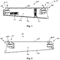
- Fig. 1
- eine erfindungsgemäße Regalkonsole mit zwei Wägevorrichtungen in einer Ansicht auf die Innenseite,
- Fig. 2
- eine Regalkonsole mit zwei Wägevorrichtungen in einer Ansicht auf die Außenseite,
- Fig. 3
- eine Regalkonsole mit zwei Wägevorrichtungen mit einer Schutzabdeckung in einer Ansicht auf die Außenseite,
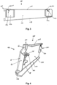
- Fig. 4
- eine Regalkonsole mit zwei Wägevorrichtungen in einer isometrischen Ansicht,
- Fig. 5
- ein Ausschnitt eines Rohlings für eine Regalkonsole nach dem Bearbeiten mit einem Metallbearbeitungslaser,
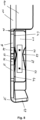
- Fig. 6
- ein Ausschnitt einer Regalkonsole mit einer Wägevorrichtung,
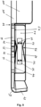
- Fig. 7
- eine Wägevorrichtung nach einer zweiten Ausführungsform,
- Fig. 8
- ein Ausschnitt einer Regalkonsole mit einer Wägevorrichtung mit zwei Dehnungsmessstreifen,
- Fig. 9
- ein Ausschnitt einer Regalkonsole mit einer Wägevorrichtung mit vier Dehnungsmessstreifen,
- Fig. 10
- ein Verfahren zur Herstellung einer Regalkonsole,
- Fig. 11
- einen Regalfachboden,
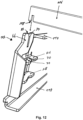
- Fig. 12
- eine Explosionszeichnung einer Wägevorrichtung und einer Strebe eines Regalfachbodens,
- Fig. 13
- ein Blockdiagramm eines Regals,
- Fig. 14
- ein Verfahren zum Betrieb eines Regals,
- Fig. 15
- ein erstes Verfahren zur Bestimmung eines Ortes auf dem Regalfachboden, an dem ein Produkt entnommen oder zugefügt wurde,
- Fig. 16
- ein zweites Verfahren zur Bestimmung eines Ortes auf dem Regalfachboden, an dem ein Produkt entnommen oder zugefügt wurde, und
- Fig. 17
- ein drittes Verfahren zur Bestimmung eines Ortes auf dem Regalfachboden, an dem ein Produkt entnommen oder zugefügt wurde.
- 1
- a shelf bracket according to the invention with two weighing devices in a view of the inside,
- 2
- a shelf console with two weighing devices in an external view,
- 3
- a shelf console with two weighing devices with a protective cover in an external view,
- 4
- a shelf console with two weighing devices in an isometric view,
- figure 5
- a section of a blank for a shelf bracket after processing with a metal processing laser,
- 6
- a section of a shelf console with a weighing device,
- 7
- a weighing device according to a second embodiment,
- 8
- a section of a shelf bracket with a weighing device with two strain gauges,
- 9
- a section of a shelf bracket with a weighing device with four strain gauges,
- 10
- a method for manufacturing a shelf bracket,
- 11
- a shelf,
- 12
- an exploded view of a weighing device and a strut of a shelf,
- 13
- a block diagram of a shelf,
- 14
- a method of operating a rack,
- 15
- a first method for determining a location on the shelf where a product was removed or added,
- 16
- a second method of determining a location on the shelf at which a product was removed or added, and
- 17
- a third method of determining a location on the shelf where a product was removed or added.
Eine optionale Abdeckung, die an den Versteifungsrippen 110 angebracht werden kann und den inneren Bereich der Regalkonsole 100 schützt, ist in
In
Der Gelenkabschnitt 22 umfasst zwei Wiegebleche 26, 28, die aus dem Metallblech wie in
Ein axiales Ende des oberen Wiegeblechs 26 ist über einen Biegeabschnitt 43 mit einem Halter 51 des Kraftaufnahmeabschnitts 20 verbunden. Das andere axiale Ende des oberen Wiegeblechs 26 ist über einen Biegeabschnitt 44 mit einem Halter 61 des Krafteinleitungsabschnitts 24 verbunden. Ein axiales Ende des unteren Wiegeblechs 28 ist über einen Biegeabschnitt 56 mit einem Halter 52 des Kraftaufnahmeabschnitts 20 verbunden. Das andere axiale Ende des unteren Wiegeblechs 28 ist über einen Biegeabschnitt 57 mit einem Halter 62 des Krafteinleitungsabschnitts 24 verbunden. Die Breite 54 des oberen Wiegeblechs 26 und die Breite 55 des unteren Wiegeblechs 28 ist im Bereich der Mitte schmaler als an den axialen Enden. Der Verlauf der Konturen 48, 49 der Breite des oberen Wiegeblechs 26 und der Verlauf der Konturen 58, 59 der Breite des unteren Wiegeblechs 28 sind nicht identisch. Außerdem sind diese Konturen 48, 49, 58, 59 nicht spiegelsymmetrisch zu Mitte. Mit diesen Konturen 48, 49, 58, 59 werden die Flächenträgheitsmomente der Wiegebleche 26, 28 eingestellt, um im Bereich der Dehnungsmesstreifen ein, im Idealfall, konstantes Flächenträgheitsmoment und somit beste Wiegeergebnisse zu erhalten. Die Dicke der Wiegebelche 26, 28 ist überall, auch in diesem Bereich, gleich und entspricht der Dicke des Blechs der anderen Teile der Wägevorrichtungen 102, 104 und des Auslegers 106.An axial end of the upper weighing
Der Kraftaufnahmeabschnitt 20 umfasst eine Basis 53 und den mit der Basis 53 verbundenen Halter 51, an dem die Biegung 43 des oberen Wiegeblechs 26 des Gelenkabschnitts 22 angebracht ist. Des Weiteren umfasst der Kraftaufnahmeabschnitt 20 den mit der Basis 53 verbundenen Halter 52, an dem die Biegung 56 des unteren Wiegeblechs 28 des Gelenkabschnitts 22 angebracht ist.The
Der Krafteinleitungsabschnitt 24 umfasst eine Basis 63 und den mit der Basis 53 verbundenen Halter 61, an dem die Biegung 44 des oberen Wiegeblechs 26 des Gelenkabschnitts 22 angebracht ist. Des Weiteren umfasst der Krafteinleitungsabschnitt 24 den mit der Basis 53 verbundenen Halter 62, an dem die Biegung 57 des unteren Wiegeblechs 28 des Gelenkabschnitts 22 angebracht ist. Um ein Stabilisierungselement 64 gegenüber der Basis 63 des Krafteinleitungsabschnitts 24 abzukanten umfasst der Krafteinleitungsabschnitt 24 in diesem Übergangsbereich eine Biegung 65. Ein in vertikaler Richtung über dem Gelenkabschnitt 22 angeordnetes Aufnahmeelement 66 umfasst einen Einschnitt 32, der zu seinem offenen Ende hin mit Schrägen 34 verbreitert ist. Der Einschnitt 32 dient dazu, eine Strebe eines Regalfachbodens momentenfrei abzustützen.The
Alle in
Der Regalfachboden 200 wird von den vier Wägevorrichtungen 261, 262, 263, 264 schwebend gehaltert. Dabei handelt es sich um die Wägevorrichtungen 102, 104, die in die Regalkonsolen 100 integriert sind. Dabei stützen eine Regalkonsole 100 links des Regalfachbodens 200 und eine Regalkonsole 100 rechts des Regalfachbodens 200 den Regalfachboden 200. Die Wägevorrichtungen 261, 262, 263, 264 stützen mit ihren Krafteinleitungsabschnitten 24 den Regalfachboden 200 an den Enden seiner Streben 206. Die Wägevorrichtungen 261, 262, 263, 264 bestimmen unabhängig voneinander eine wirkende Gewichtskraft, die durch den Regalfachboden 200 und der in den Regalbereichen 211, 213, 215 abgelegten Produkte entsteht. Dabei wirkt auf jede Wägevorrichtungen 261, 262, 263, 264 anteilig von dem Gesamtgewicht eine einzelne Gewichtskraft. Die Daten aus den Wägevorrichtungen 261, 262, 263, 264 werden an eine Auswerteinheit 265 übermittelt. Die Auswerteeinheit bestimmt aus den einzelnen Gewichtsdaten der Wägevorrichtungen 261, 262, 263, 264 Schwerpunktkoordinaten des Regalfachbodens 200. Die Koordinaten im Regalbereich 211, 213, 215 beginnen in einer Ecke bei der Wägevorrichtung 263 mit den Koordinaten (0, 0) und erstrecken sich in waagrechter Richtung X und in senkrechter Richtung Y.The
Zur Veranschaulichung der Schwerpunktsermittlung werden den Wägevorrichtungen 261, 262, 263, 264 wie in
Die Bildung des Schwerpunkts in X Richtung bestimmt sich wie folgt: ![]()
![]()
Die Bildung des Schwerpunkts in Y Richtung bestimmt sich wie folgt: ![]()
![]()
Mit einem entsprechenden Normierungsfaktor, der die Größe des Regalfachbodens 200 berücksichtigt, sind Koordinaten in dem Regalbereich 211, 213, 215 bestimmbar, die den Schwerpunktkoordinaten des Regalfachbodens 200 entsprechen. Diese Koordinaten werden in der Auswerteeinheit 265 auf Basis der Daten der Wägevorrichtungen 261, 262, 263, 264 ermittelt. Des Weiteren bildet die Auswerteeinheit 265 ein Gesamtgewicht W261 + W262 + W263 + W264. Die Schwerpunktkoordinaten und das Gesamtgewicht werden von der Auswerteeinheit 265 an eine Steuereinrichtung 241 übermittelt. Das Regal umfasst einen Speicher 244, in dem eine Zuordnung zwischen Schwerpunktkoordinaten und Regalbereichen 211, 213, 215 abgelegt ist. Im Speicher 244 ist des Weiteren für jeden Regalbereich 211, 213, 215 das durchschnittliche Gewicht eines Stücks einer Ware in diesem Regalbereich 211, 213, 215 abgelegt. Im Speicher 244 ist für jeden Regalbereich 211, 213, 215 der aktuelle Warenbestand, das heißt die aktuelle Anzahl von Waren/Stück in diesem Regalbereich 211, 213, 215 gespeichert. Mit dieser Anordnung sind neben den in
Die Funktionen verschiedener in den Zeichnungen gezeigter Elemente, inklusive der Funktionsblöcke, können durch dezidierte Hardware oder durch generische Hardware, die in der Lage ist Software auszuführen, im Zusammenhang mit der entsprechenden Software, realisiert werden. Falls die Funktionen mittels eines Prozessors zur Verfügung gestellt werden, können sie durch einen einzigen dezidierten Prozessor, einen einzigen geteilten Prozessor oder mehrere generische Prozessoren, die wiederum geteilt sein können, zur Verfügung gestellt werden. Die Funktionen können, ohne Einschränkung, durch einen digital signal processor (DSP), Netzwerk Prozessor, application specific integrated circuit (ASIC), field programmable gate array (FPGA), read only memory (ROM) mit gespeicherter Software, random access memory (RAM), und nichtflüchtige Speicher zur Verfügung gestellt werden.The functions of various elements shown in the drawings, including the function blocks, can be realized by dedicated hardware or by generic hardware capable of executing software associated with the corresponding software. If the functions are provided by a processor, they may be provided by a single dedicated processor, a single shared processor, or multiple generic processors, which in turn may be shared. The functions can be implemented, without limitation, by a digital signal processor (DSP), network processor, application specific integrated circuit (ASIC), field programmable gate array (FPGA), read only memory (ROM) with stored software, random access memory (RAM ), and non-volatile memory are made available.
Claims (18)
- Rack support having at least one weighing device (102, 104), which rack support is suitable for being secured in a vertically arranged rack rail and has an anchoring device (108) and an extension arm (106) for supporting a shelf (200), wherein, in the state in which the rack support (100) is secured in a rack rail, the extension arm (106) projects from the rack rail in a substantially horizontal direction and is formed, in particular, by a vertically arranged plate, wherein, in a Cartesian coordinate system, the extent of the extension arm (106) in the horizontal plane defines a Y-direction, the vertical direction defines a Z-direction and the direction perpendicular to the Y-direction and the Z-direction defines an X-direction, wherein the at least one weighing device has a force-introducing section (24), a joint section (22) and a force-absorbing section (20), and that the joint section (22) consists of two weighing plates (26, 28) which run horizontally and parallel to one another, characterized in that the force-absorbing section (20) and the force-introducing section (24) consist at least partially of vertically running plates (51, 52, 53, 61, 62, 63), and in that the width of the weighing plates (26, 28) in the X direction is narrowest in the region of the middle of the joint section (22) and increases in the direction of the force-introducing section (24) and the force-absorbing section (20), and in that the thickness of the upper weighing plate (26) and the thickness of the lower weighing plate (28) in the Z-direction is the same.
- Rack support according to Claim 1, characterized in that the force-absorbing section (20), the joint section (22) and the force-introducing section (24) are formed in one piece.
- Rack support according to Claim 1 or 2, characterized in that the vertical plate of the force-introducing portion (24) and/or of the force-absorbing section (20) runs laterally next to the weighing plates (26, 28) in the X-direction.
- Rack support according to one of Claims 1 to 3, characterized in that the force-introducing section comprises a receiving element (66) for a strut (206) of a shelf (200), wherein the receiving element (66) is located above the position of the joint section (22) in the Z-direction, and wherein in particular the receiving element (66) has an incision (32), oriented in the vertical direction from above, for insertion of a strut (206) of a shelf (200).
- Rack support according to one of Claims 1 to 4, characterized in that the force-introducing section (24) comprises a stabilization element (64), wherein the stabilization element (64) is designed in particular as a plate oriented in the X-Z direction.
- Rack support according to one of Claims 1 to 5, characterized in that the thickness of the plate of the force-absorbing section (20), the joint section (22) and the force-introducing section (24) is the same, and in particular in that the plate is between 1.5 mm and 6 mm, in particular between 2 mm and 3 mm, thick.
- Rack support according to one of Claims 1 to 6, characterized in that the two weighing plates (26, 28) are arranged one above the other in the Z-direction, and in that in each case two strain gauges (70) are fitted to the top side of the upper weighing plate (26) and to the bottom side of the lower weighing plate (28), and wherein the four strain gauges (70) of the weighing device are interconnected to form a Wheatstone measuring bridge, and wherein in particular the wiring of the two strain gauges (70) arranged on the top side and the two strain gauges (70) arranged on the top side are fitted on a strain gauge film (68), and wherein in particular the wiring of the two strain gauges (70) arranged on the bottom side and the two strain gauges (70) arranged on the bottom side are fitted on a strain gauge film (68).
- Rack support according to one of Claims 1 to 6, characterized in that the two weighing plates (26, 28) are arranged one above the other in the Z-direction, and in that four strain gauges (70) are fitted to the top side of the upper weighing plate (26), in each case two of said four strain gauges being arranged next to one another on the upper weighing plate (26) in the X-direction on the upper weighing plate (26), and wherein the four strain gauges (70) of the weighing device are interconnected to form a Wheatstone measuring bridge, and wherein in particular the wiring of the four strain gauges (70) and the four strain gauges (70) are fitted on a strain gauge (68).
- Rack support according to one of Claims 1 to 8, characterized in that the contour of the width of the upper weighing plate (26) and the contour of the width of the lower weighing plate (28) are similar but not exactly the same.
- Rack support according to one of Claims 1 to 9, characterized in that the weighing device comprises an overload stop which is defined by the height of a gap (40) between the extension arm (106) and the force introduction (24).
- Rack support according to one of Claims 1 to 10, characterized in that the rack support comprises two weighing devices (102, 104), and the extension arm (106) and the two weighing devices (102, 104) and in particular the anchoring device (108) are formed in one piece.
- Method for producing a rack support according to one of Claims 1 to 11, the method comprising the following steps:- cutting out, using a metal-machining laser, a blank for at least one weighing device (102, 104) from a metal sheet,- bending the blank using a bending tool, so that at least one stabilization element (64) and in particular reinforcing ribs (110) are created,- bending the blank using a bending tool, so that an upper weighing plate (26) and a lower weighing plate (28) are created,- applying at least one strain gauge film having at least two strain gauges (70) onto the upper weighing plate (26) or onto the upper weighing plate (26) and beneath the lower weighing plate (28),- connecting the strain gauge film to at least one printed circuit board with electronics arranged on it, in particular an analog-digital converter for processing at least one output signal from the at least one strain gauge film.
- Method for producing a weighing device for a rack support according to Claim 12, wherein the step of cutting out, using a metal-machining laser, a blank for at least one weighing device (102, 104) from a metal sheet comprises the step of cutting out a blank for two weighing devices and an extension arm (106).
- Method for producing a weighing device for a rack support according to Claim 12, wherein the method comprises the following steps:- bending, using a bending tool, securing sides onto the reinforcing ribs (110),- drilling, using a drilling device, fastening holes into the fastening sides and drilling fastening holes into an extension arm (106) of the rack support, and- connecting the weighing device (102, 104) to the extension arm (106) of a rack support by means of the fastening holes and screws.
- Rack consisting of at least two vertically arranged rack rails and at least two rack supports (100) according to one of Claims 1 to 11 arranged at the same height in each case of a rack rail and at least one shelf (200) placed on the two rack supports (100) arranged at the same height, wherein the shelf (200) comprises two struts (206) of parallel design, which struts are supported, by way of their ends, on the force-introducing sections (24) of in each case two weighing devices (102, 104), and wherein the rack comprises an evaluation unit (265) which, at periodic intervals or in the event of a change in the total weight which is detected by the four weighing devices on the force-introducing sections (24) of which the shelf (200) rests, determines new centroid coordinates from the data from the weighing devices (261, 262, 263, 264) and transmits these centroid coordinates to a control unit (241), wherein the control unit (241) determines a rack region (211, 213, 215) based on changes in the centroid coordinates, wherein the control unit (41) establishes from the change in the total weight the weight of the goods removed from or added to the determined rack region (211, 213, 215) and updates the inventory, stored in a memory (244), for this rack region (211, 213, 215).
- Rack according to Claim 15, characterized in that the evaluation unit (265), in the event of a change in the total weight, determines a vector between the previous centroid coordinates and the new centroid coordinates, and in that the rack region (211, 213, 215) established by the control unit (241) is determined from the vector and the total weight by the control unit (241) .
- Rack according to Claim 15, characterized in that the evaluation unit (265) periodically and simultaneously tares all the weighing devices (61, 62, 63, 64).
- Rack according to Claim 15, characterized in that the evaluation unit (265), for the purpose of determining the new centroid coordinates for each weighing device (261, 262, 263, 264), calculates the difference between a new weight value and a previous weight value and determines the new centroid coordinates from the four difference values.
Priority Applications (2)
| Application Number | Priority Date | Filing Date | Title |
|---|---|---|---|
| EP19220146.5A EP3845873B1 (en) | 2019-12-30 | 2019-12-30 | Shelf bracket |
| US17/124,508 US11668599B2 (en) | 2019-12-30 | 2020-12-17 | Shelf bracket assembly |
Applications Claiming Priority (1)
| Application Number | Priority Date | Filing Date | Title |
|---|---|---|---|
| EP19220146.5A EP3845873B1 (en) | 2019-12-30 | 2019-12-30 | Shelf bracket |
Publications (2)
| Publication Number | Publication Date |
|---|---|
| EP3845873A1 EP3845873A1 (en) | 2021-07-07 |
| EP3845873B1 true EP3845873B1 (en) | 2023-02-15 |
Family
ID=69061171
Family Applications (1)
| Application Number | Title | Priority Date | Filing Date |
|---|---|---|---|
| EP19220146.5A Active EP3845873B1 (en) | 2019-12-30 | 2019-12-30 | Shelf bracket |
Country Status (2)
| Country | Link |
|---|---|
| US (1) | US11668599B2 (en) |
| EP (1) | EP3845873B1 (en) |
Families Citing this family (3)
| Publication number | Priority date | Publication date | Assignee | Title |
|---|---|---|---|---|
| EP3845873B1 (en) | 2019-12-30 | 2023-02-15 | Bizerba SE & Co. KG | Shelf bracket |
| EP3845872B1 (en) | 2019-12-30 | 2023-07-12 | Bizerba SE & Co. KG | Weighing cell |
| EP3845874A1 (en) * | 2019-12-30 | 2021-07-07 | Bizerba SE & Co. KG | Shelf bracket |
Family Cites Families (34)
| Publication number | Priority date | Publication date | Assignee | Title |
|---|---|---|---|---|
| US4396079A (en) * | 1981-07-29 | 1983-08-02 | Sensor Developments, Inc. | Weighing system |
| US4655305A (en) | 1985-06-24 | 1987-04-07 | Revere Corporation Of America | Strain gage type platform sensor |
| DE3621378A1 (en) | 1986-06-26 | 1988-01-14 | Erichsen A M Gmbh | RECEIVER FOR DEVICES FOR MEASURING PRESSURE, TENSION, SHEAR FORCES OR TORQUE AND METHOD FOR THE PRODUCTION THEREOF |
| DE8713483U1 (en) | 1987-10-08 | 1989-02-02 | Krups Stiftung | |
| US5293007A (en) | 1992-04-02 | 1994-03-08 | Stress-Tek, Inc. | Method for moment balancing a parallel beam load cell and the article produced thereby |
| JP3314107B2 (en) | 1993-07-22 | 2002-08-12 | 株式会社イシダ | Accelerometer mounting structure |
| US5623128A (en) * | 1994-03-01 | 1997-04-22 | Mettler-Toledo, Inc. | Load cell with modular calibration components |
| US5510581A (en) | 1994-05-18 | 1996-04-23 | Angel; Shlomo | Mass-produced flat multiple-beam load cell and scales incorporating it |
| KR100191261B1 (en) * | 1994-07-04 | 1999-06-15 | 구보 미츠오 | Loadcell unit |
| US6318184B1 (en) | 1997-06-02 | 2001-11-20 | The Penn State Research Foundation | Beam strain gauge |
| US6215078B1 (en) * | 1998-12-22 | 2001-04-10 | Ncr Corporation | Method and apparatus for determining a stable weight measurement for use in a security software application of a self-service checkout terminal |
| SE515184C2 (en) | 1999-12-03 | 2001-06-25 | Abb Ab | Load cell and use of a load cell |
| ATE298884T1 (en) | 2000-09-23 | 2005-07-15 | Digi Sens Ag | LOGISTICS SCALE |
| US6817255B2 (en) | 2001-09-12 | 2004-11-16 | The Board Of Trustees Of The University Of Illinois | Apparatus and method for testing of microscale to nanoscale thin films |
| US6789435B2 (en) | 2002-10-01 | 2004-09-14 | Hottinger Baldwin Measurements, Inc. | Hermetically sealed load cell |
| US7240571B2 (en) | 2004-09-30 | 2007-07-10 | Walker Robert R | On-board scale sensor with mechanical amplification and improved output signal apparatus and method |
| US6988412B1 (en) | 2004-11-30 | 2006-01-24 | Endevco Corporation | Piezoresistive strain concentrator |
| JP5378993B2 (en) | 2006-05-30 | 2013-12-25 | ザ・ティムケン・カンパニー | Displacement, strain and force sensors |
| EP2120023B1 (en) | 2008-05-15 | 2012-04-18 | Mettler-Toledo AG | Capsuled load cell with eccentric load calibration |
| DE102008056715B4 (en) | 2008-11-11 | 2010-09-23 | Sartorius Ag | Force plate |
| KR100919478B1 (en) | 2009-06-16 | 2009-09-28 | 박흥준 | Load measuring transducer using induced voltage for overcoming eccentric error and load measurement system using the same |
| US8935964B2 (en) | 2012-12-17 | 2015-01-20 | Tyco Electronics Corporation | Transducer for and method of measuring normal force of a compliant pin |
| AU2014218521A1 (en) | 2013-02-22 | 2015-09-24 | Breakaway Innovations Pty Ltd | Crank arm electronics packaging |
| JP5728745B2 (en) | 2013-03-27 | 2015-06-03 | 株式会社タニタ | Straining body, load cell and weight measuring device |
| US10121121B1 (en) * | 2015-12-28 | 2018-11-06 | Amazon Technologies, Inc. | Smart shelves |
| US10198710B1 (en) * | 2016-03-28 | 2019-02-05 | Amazon Technologies, Inc. | System to determine a change in weight at a load cell |
| DE102017104367A1 (en) | 2017-03-02 | 2018-09-06 | Bizerba SE & Co. KG | Load cell for a balance |
| US10746589B1 (en) | 2017-06-21 | 2020-08-18 | Amazon Technologies, Inc. | Crossbar mechanism for coupling to fixture |
| US10809122B1 (en) * | 2017-06-21 | 2020-10-20 | Amazon Technologies, Inc. | Components of weighing module and mechanism for coupling to fixture |
| JP2021526651A (en) * | 2018-05-16 | 2021-10-07 | シェケル スケールズ(2008)リミテッド | Weighing load cells and configurations that utilize them on shelves |
| US10969267B1 (en) | 2019-03-01 | 2021-04-06 | Amazon Technologies, Inc. | Parallel planar weight sensing device |
| US11125607B1 (en) | 2019-05-30 | 2021-09-21 | Amazon Technologies, Inc. | Integrated multi-lane weight measuring device |
| CN110169685A (en) * | 2019-07-04 | 2019-08-27 | 深圳市尤鸟信息技术有限公司 | A kind of multi-functional laminate shelf |
| EP3845873B1 (en) | 2019-12-30 | 2023-02-15 | Bizerba SE & Co. KG | Shelf bracket |
-
2019
- 2019-12-30 EP EP19220146.5A patent/EP3845873B1/en active Active
-
2020
- 2020-12-17 US US17/124,508 patent/US11668599B2/en active Active
Also Published As
| Publication number | Publication date |
|---|---|
| US11668599B2 (en) | 2023-06-06 |
| EP3845873A1 (en) | 2021-07-07 |
| US20210199490A1 (en) | 2021-07-01 |
Similar Documents
| Publication | Publication Date | Title |
|---|---|---|
| EP3845873B1 (en) | Shelf bracket | |
| EP3845874A1 (en) | Shelf bracket | |
| EP1319173B1 (en) | Logistics scales | |
| EP3620760B1 (en) | Selling device with integrated stock control | |
| DE102007015734B4 (en) | System for detecting objects colliding with a self-propelled vehicle | |
| DE102018009247B4 (en) | Six-axis force sensor with position detection | |
| DE60303032T2 (en) | STORAGE SYSTEM | |
| DE102008056715B4 (en) | Force plate | |
| DE2902061A1 (en) | TOP SCALE SCALE | |
| EP0296459A1 (en) | Frame for a textile machine, particularly for a spinning or twisting machine | |
| DE102009032423B4 (en) | Horizontal shelf support, which is designed for horizontal installation in a rack, and method for producing such a horizontal shelf carrier | |
| DE19548919B4 (en) | Multiple overload protection for electronic scales | |
| DE60030830T2 (en) | weighing System | |
| DE3141767A1 (en) | POWER CONVERTER | |
| DE102008048367C5 (en) | Storage device with overhang control | |
| EP0014460A2 (en) | Platform balance using strain sensors attached to flexure plates | |
| DE7703229U1 (en) | METAL CONSOLE FOR HANGING IN PERFORATED WALL PLATES | |
| CH680535A5 (en) | ||
| DE60302312T2 (en) | Press brake with a substantially dimensionally stable tool holding bar | |
| DE3936364C2 (en) | ||
| DE102008056714B4 (en) | Electronic scale | |
| DE19857381A1 (en) | Weight pick-up has parallel feeders with wire strain gauges on thin spots in guide rods | |
| DE202009009414U1 (en) | Horizontal support, which is designed for horizontal installation in a shelf, and shelf with such a horizontal support | |
| DE7732143U1 (en) | Inner wall cladding for a transport container or vehicle body | |
| DE102021202125B3 (en) | Motor vehicle with a trunk, the trunk being part of a load scale for weighing objects loaded in the motor vehicle |
Legal Events
| Date | Code | Title | Description |
|---|---|---|---|
| PUAI | Public reference made under article 153(3) epc to a published international application that has entered the european phase |
Free format text: ORIGINAL CODE: 0009012 |
|
| STAA | Information on the status of an ep patent application or granted ep patent |
Free format text: STATUS: THE APPLICATION HAS BEEN PUBLISHED |
|
| AK | Designated contracting states |
Kind code of ref document: A1 Designated state(s): AL AT BE BG CH CY CZ DE DK EE ES FI FR GB GR HR HU IE IS IT LI LT LU LV MC MK MT NL NO PL PT RO RS SE SI SK SM TR |
|
| STAA | Information on the status of an ep patent application or granted ep patent |
Free format text: STATUS: REQUEST FOR EXAMINATION WAS MADE |
|
| 17P | Request for examination filed |
Effective date: 20211208 |
|
| RBV | Designated contracting states (corrected) |
Designated state(s): AL AT BE BG CH CY CZ DE DK EE ES FI FR GB GR HR HU IE IS IT LI LT LU LV MC MK MT NL NO PL PT RO RS SE SI SK SM TR |
|
| GRAP | Despatch of communication of intention to grant a patent |
Free format text: ORIGINAL CODE: EPIDOSNIGR1 |
|
| STAA | Information on the status of an ep patent application or granted ep patent |
Free format text: STATUS: GRANT OF PATENT IS INTENDED |
|
| INTG | Intention to grant announced |
Effective date: 20221114 |
|
| GRAS | Grant fee paid |
Free format text: ORIGINAL CODE: EPIDOSNIGR3 |
|
| GRAA | (expected) grant |
Free format text: ORIGINAL CODE: 0009210 |
|
| STAA | Information on the status of an ep patent application or granted ep patent |
Free format text: STATUS: THE PATENT HAS BEEN GRANTED |
|
| AK | Designated contracting states |
Kind code of ref document: B1 Designated state(s): AL AT BE BG CH CY CZ DE DK EE ES FI FR GB GR HR HU IE IS IT LI LT LU LV MC MK MT NL NO PL PT RO RS SE SI SK SM TR |
|
| REG | Reference to a national code |
Ref country code: CH Ref legal event code: EP Ref country code: GB Ref legal event code: FG4D Free format text: NOT ENGLISH |
|
| REG | Reference to a national code |
Ref country code: DE Ref legal event code: R096 Ref document number: 502019006987 Country of ref document: DE |
|
| REG | Reference to a national code |
Ref country code: AT Ref legal event code: REF Ref document number: 1548450 Country of ref document: AT Kind code of ref document: T Effective date: 20230315 Ref country code: IE Ref legal event code: FG4D Free format text: LANGUAGE OF EP DOCUMENT: GERMAN |
|
| REG | Reference to a national code |
Ref country code: LT Ref legal event code: MG9D |
|
| REG | Reference to a national code |
Ref country code: NL Ref legal event code: MP Effective date: 20230215 |
|
| PG25 | Lapsed in a contracting state [announced via postgrant information from national office to epo] |
Ref country code: RS Free format text: LAPSE BECAUSE OF FAILURE TO SUBMIT A TRANSLATION OF THE DESCRIPTION OR TO PAY THE FEE WITHIN THE PRESCRIBED TIME-LIMIT Effective date: 20230215 Ref country code: PT Free format text: LAPSE BECAUSE OF FAILURE TO SUBMIT A TRANSLATION OF THE DESCRIPTION OR TO PAY THE FEE WITHIN THE PRESCRIBED TIME-LIMIT Effective date: 20230615 Ref country code: NO Free format text: LAPSE BECAUSE OF FAILURE TO SUBMIT A TRANSLATION OF THE DESCRIPTION OR TO PAY THE FEE WITHIN THE PRESCRIBED TIME-LIMIT Effective date: 20230515 Ref country code: NL Free format text: LAPSE BECAUSE OF FAILURE TO SUBMIT A TRANSLATION OF THE DESCRIPTION OR TO PAY THE FEE WITHIN THE PRESCRIBED TIME-LIMIT Effective date: 20230215 Ref country code: LV Free format text: LAPSE BECAUSE OF FAILURE TO SUBMIT A TRANSLATION OF THE DESCRIPTION OR TO PAY THE FEE WITHIN THE PRESCRIBED TIME-LIMIT Effective date: 20230215 Ref country code: LT Free format text: LAPSE BECAUSE OF FAILURE TO SUBMIT A TRANSLATION OF THE DESCRIPTION OR TO PAY THE FEE WITHIN THE PRESCRIBED TIME-LIMIT Effective date: 20230215 Ref country code: HR Free format text: LAPSE BECAUSE OF FAILURE TO SUBMIT A TRANSLATION OF THE DESCRIPTION OR TO PAY THE FEE WITHIN THE PRESCRIBED TIME-LIMIT Effective date: 20230215 Ref country code: ES Free format text: LAPSE BECAUSE OF FAILURE TO SUBMIT A TRANSLATION OF THE DESCRIPTION OR TO PAY THE FEE WITHIN THE PRESCRIBED TIME-LIMIT Effective date: 20230215 |
|
| PG25 | Lapsed in a contracting state [announced via postgrant information from national office to epo] |
Ref country code: SE Free format text: LAPSE BECAUSE OF FAILURE TO SUBMIT A TRANSLATION OF THE DESCRIPTION OR TO PAY THE FEE WITHIN THE PRESCRIBED TIME-LIMIT Effective date: 20230215 Ref country code: PL Free format text: LAPSE BECAUSE OF FAILURE TO SUBMIT A TRANSLATION OF THE DESCRIPTION OR TO PAY THE FEE WITHIN THE PRESCRIBED TIME-LIMIT Effective date: 20230215 Ref country code: IS Free format text: LAPSE BECAUSE OF FAILURE TO SUBMIT A TRANSLATION OF THE DESCRIPTION OR TO PAY THE FEE WITHIN THE PRESCRIBED TIME-LIMIT Effective date: 20230615 Ref country code: GR Free format text: LAPSE BECAUSE OF FAILURE TO SUBMIT A TRANSLATION OF THE DESCRIPTION OR TO PAY THE FEE WITHIN THE PRESCRIBED TIME-LIMIT Effective date: 20230516 Ref country code: FI Free format text: LAPSE BECAUSE OF FAILURE TO SUBMIT A TRANSLATION OF THE DESCRIPTION OR TO PAY THE FEE WITHIN THE PRESCRIBED TIME-LIMIT Effective date: 20230215 |
|
| PG25 | Lapsed in a contracting state [announced via postgrant information from national office to epo] |
Ref country code: SM Free format text: LAPSE BECAUSE OF FAILURE TO SUBMIT A TRANSLATION OF THE DESCRIPTION OR TO PAY THE FEE WITHIN THE PRESCRIBED TIME-LIMIT Effective date: 20230215 Ref country code: RO Free format text: LAPSE BECAUSE OF FAILURE TO SUBMIT A TRANSLATION OF THE DESCRIPTION OR TO PAY THE FEE WITHIN THE PRESCRIBED TIME-LIMIT Effective date: 20230215 Ref country code: EE Free format text: LAPSE BECAUSE OF FAILURE TO SUBMIT A TRANSLATION OF THE DESCRIPTION OR TO PAY THE FEE WITHIN THE PRESCRIBED TIME-LIMIT Effective date: 20230215 Ref country code: DK Free format text: LAPSE BECAUSE OF FAILURE TO SUBMIT A TRANSLATION OF THE DESCRIPTION OR TO PAY THE FEE WITHIN THE PRESCRIBED TIME-LIMIT Effective date: 20230215 Ref country code: CZ Free format text: LAPSE BECAUSE OF FAILURE TO SUBMIT A TRANSLATION OF THE DESCRIPTION OR TO PAY THE FEE WITHIN THE PRESCRIBED TIME-LIMIT Effective date: 20230215 |
|
| REG | Reference to a national code |
Ref country code: DE Ref legal event code: R097 Ref document number: 502019006987 Country of ref document: DE |
|
| PG25 | Lapsed in a contracting state [announced via postgrant information from national office to epo] |
Ref country code: SK Free format text: LAPSE BECAUSE OF FAILURE TO SUBMIT A TRANSLATION OF THE DESCRIPTION OR TO PAY THE FEE WITHIN THE PRESCRIBED TIME-LIMIT Effective date: 20230215 |
|
| PLBE | No opposition filed within time limit |
Free format text: ORIGINAL CODE: 0009261 |
|
| STAA | Information on the status of an ep patent application or granted ep patent |
Free format text: STATUS: NO OPPOSITION FILED WITHIN TIME LIMIT |
|
| PGFP | Annual fee paid to national office [announced via postgrant information from national office to epo] |
Ref country code: GB Payment date: 20231220 Year of fee payment: 5 |
|
| 26N | No opposition filed |
Effective date: 20231116 |
|
| PG25 | Lapsed in a contracting state [announced via postgrant information from national office to epo] |
Ref country code: SI Free format text: LAPSE BECAUSE OF FAILURE TO SUBMIT A TRANSLATION OF THE DESCRIPTION OR TO PAY THE FEE WITHIN THE PRESCRIBED TIME-LIMIT Effective date: 20230215 |
|
| PGFP | Annual fee paid to national office [announced via postgrant information from national office to epo] |
Ref country code: FR Payment date: 20231219 Year of fee payment: 5 Ref country code: DE Payment date: 20231214 Year of fee payment: 5 |