EP3369961A1 - Rotary inertia mass damper - Google Patents
Rotary inertia mass damper Download PDFInfo
- Publication number
- EP3369961A1 EP3369961A1 EP16859650.0A EP16859650A EP3369961A1 EP 3369961 A1 EP3369961 A1 EP 3369961A1 EP 16859650 A EP16859650 A EP 16859650A EP 3369961 A1 EP3369961 A1 EP 3369961A1
- Authority
- EP
- European Patent Office
- Prior art keywords
- screw shaft
- coupling portion
- rotary
- shaft
- inertia mass
- Prior art date
- Legal status (The legal status is an assumption and is not a legal conclusion. Google has not performed a legal analysis and makes no representation as to the accuracy of the status listed.)
- Withdrawn
Links
- 230000008878 coupling Effects 0.000 claims abstract description 45
- 238000010168 coupling process Methods 0.000 claims abstract description 45
- 238000005859 coupling reaction Methods 0.000 claims abstract description 45
- 230000033001 locomotion Effects 0.000 claims abstract description 18
- 230000000717 retained effect Effects 0.000 claims abstract description 11
- 230000005540 biological transmission Effects 0.000 claims description 37
- 230000002093 peripheral effect Effects 0.000 claims description 7
- 230000001133 acceleration Effects 0.000 abstract description 27
- 238000010276 construction Methods 0.000 abstract description 23
- 238000006243 chemical reaction Methods 0.000 abstract description 19
- 230000014509 gene expression Effects 0.000 description 8
- 238000006073 displacement reaction Methods 0.000 description 7
- 230000003321 amplification Effects 0.000 description 2
- 238000013016 damping Methods 0.000 description 2
- 230000000694 effects Effects 0.000 description 2
- 239000012530 fluid Substances 0.000 description 2
- 238000003199 nucleic acid amplification method Methods 0.000 description 2
Images


Classifications
-
- E—FIXED CONSTRUCTIONS
- E04—BUILDING
- E04H—BUILDINGS OR LIKE STRUCTURES FOR PARTICULAR PURPOSES; SWIMMING OR SPLASH BATHS OR POOLS; MASTS; FENCING; TENTS OR CANOPIES, IN GENERAL
- E04H9/00—Buildings, groups of buildings or shelters adapted to withstand or provide protection against abnormal external influences, e.g. war-like action, earthquake or extreme climate
- E04H9/02—Buildings, groups of buildings or shelters adapted to withstand or provide protection against abnormal external influences, e.g. war-like action, earthquake or extreme climate withstanding earthquake or sinking of ground
- E04H9/021—Bearing, supporting or connecting constructions specially adapted for such buildings
- E04H9/023—Bearing, supporting or connecting constructions specially adapted for such buildings and comprising rolling elements, e.g. balls, pins
-
- E—FIXED CONSTRUCTIONS
- E04—BUILDING
- E04H—BUILDINGS OR LIKE STRUCTURES FOR PARTICULAR PURPOSES; SWIMMING OR SPLASH BATHS OR POOLS; MASTS; FENCING; TENTS OR CANOPIES, IN GENERAL
- E04H9/00—Buildings, groups of buildings or shelters adapted to withstand or provide protection against abnormal external influences, e.g. war-like action, earthquake or extreme climate
- E04H9/02—Buildings, groups of buildings or shelters adapted to withstand or provide protection against abnormal external influences, e.g. war-like action, earthquake or extreme climate withstanding earthquake or sinking of ground
- E04H9/021—Bearing, supporting or connecting constructions specially adapted for such buildings
- E04H9/0215—Bearing, supporting or connecting constructions specially adapted for such buildings involving active or passive dynamic mass damping systems
-
- F—MECHANICAL ENGINEERING; LIGHTING; HEATING; WEAPONS; BLASTING
- F16—ENGINEERING ELEMENTS AND UNITS; GENERAL MEASURES FOR PRODUCING AND MAINTAINING EFFECTIVE FUNCTIONING OF MACHINES OR INSTALLATIONS; THERMAL INSULATION IN GENERAL
- F16F—SPRINGS; SHOCK-ABSORBERS; MEANS FOR DAMPING VIBRATION
- F16F15/00—Suppression of vibrations in systems; Means or arrangements for avoiding or reducing out-of-balance forces, e.g. due to motion
- F16F15/02—Suppression of vibrations of non-rotating, e.g. reciprocating systems; Suppression of vibrations of rotating systems by use of members not moving with the rotating systems
-
- F—MECHANICAL ENGINEERING; LIGHTING; HEATING; WEAPONS; BLASTING
- F16—ENGINEERING ELEMENTS AND UNITS; GENERAL MEASURES FOR PRODUCING AND MAINTAINING EFFECTIVE FUNCTIONING OF MACHINES OR INSTALLATIONS; THERMAL INSULATION IN GENERAL
- F16F—SPRINGS; SHOCK-ABSORBERS; MEANS FOR DAMPING VIBRATION
- F16F15/00—Suppression of vibrations in systems; Means or arrangements for avoiding or reducing out-of-balance forces, e.g. due to motion
- F16F15/02—Suppression of vibrations of non-rotating, e.g. reciprocating systems; Suppression of vibrations of rotating systems by use of members not moving with the rotating systems
- F16F15/023—Suppression of vibrations of non-rotating, e.g. reciprocating systems; Suppression of vibrations of rotating systems by use of members not moving with the rotating systems using fluid means
-
- F—MECHANICAL ENGINEERING; LIGHTING; HEATING; WEAPONS; BLASTING
- F16—ENGINEERING ELEMENTS AND UNITS; GENERAL MEASURES FOR PRODUCING AND MAINTAINING EFFECTIVE FUNCTIONING OF MACHINES OR INSTALLATIONS; THERMAL INSULATION IN GENERAL
- F16F—SPRINGS; SHOCK-ABSORBERS; MEANS FOR DAMPING VIBRATION
- F16F15/00—Suppression of vibrations in systems; Means or arrangements for avoiding or reducing out-of-balance forces, e.g. due to motion
- F16F15/02—Suppression of vibrations of non-rotating, e.g. reciprocating systems; Suppression of vibrations of rotating systems by use of members not moving with the rotating systems
- F16F15/023—Suppression of vibrations of non-rotating, e.g. reciprocating systems; Suppression of vibrations of rotating systems by use of members not moving with the rotating systems using fluid means
- F16F15/0235—Suppression of vibrations of non-rotating, e.g. reciprocating systems; Suppression of vibrations of rotating systems by use of members not moving with the rotating systems using fluid means where a rotating member is in contact with fluid
-
- F—MECHANICAL ENGINEERING; LIGHTING; HEATING; WEAPONS; BLASTING
- F16—ENGINEERING ELEMENTS AND UNITS; GENERAL MEASURES FOR PRODUCING AND MAINTAINING EFFECTIVE FUNCTIONING OF MACHINES OR INSTALLATIONS; THERMAL INSULATION IN GENERAL
- F16F—SPRINGS; SHOCK-ABSORBERS; MEANS FOR DAMPING VIBRATION
- F16F7/00—Vibration-dampers; Shock-absorbers
- F16F7/10—Vibration-dampers; Shock-absorbers using inertia effect
-
- F—MECHANICAL ENGINEERING; LIGHTING; HEATING; WEAPONS; BLASTING
- F16—ENGINEERING ELEMENTS AND UNITS; GENERAL MEASURES FOR PRODUCING AND MAINTAINING EFFECTIVE FUNCTIONING OF MACHINES OR INSTALLATIONS; THERMAL INSULATION IN GENERAL
- F16F—SPRINGS; SHOCK-ABSORBERS; MEANS FOR DAMPING VIBRATION
- F16F7/00—Vibration-dampers; Shock-absorbers
- F16F7/10—Vibration-dampers; Shock-absorbers using inertia effect
- F16F7/1022—Vibration-dampers; Shock-absorbers using inertia effect the linear oscillation movement being converted into a rotational movement of the inertia member, e.g. using a pivoted mass
-
- F—MECHANICAL ENGINEERING; LIGHTING; HEATING; WEAPONS; BLASTING
- F16—ENGINEERING ELEMENTS AND UNITS; GENERAL MEASURES FOR PRODUCING AND MAINTAINING EFFECTIVE FUNCTIONING OF MACHINES OR INSTALLATIONS; THERMAL INSULATION IN GENERAL
- F16F—SPRINGS; SHOCK-ABSORBERS; MEANS FOR DAMPING VIBRATION
- F16F2230/00—Purpose; Design features
- F16F2230/24—Detecting or preventing malfunction, e.g. fail safe
-
- F—MECHANICAL ENGINEERING; LIGHTING; HEATING; WEAPONS; BLASTING
- F16—ENGINEERING ELEMENTS AND UNITS; GENERAL MEASURES FOR PRODUCING AND MAINTAINING EFFECTIVE FUNCTIONING OF MACHINES OR INSTALLATIONS; THERMAL INSULATION IN GENERAL
- F16F—SPRINGS; SHOCK-ABSORBERS; MEANS FOR DAMPING VIBRATION
- F16F2232/00—Nature of movement
- F16F2232/06—Translation-to-rotary conversion
-
- F—MECHANICAL ENGINEERING; LIGHTING; HEATING; WEAPONS; BLASTING
- F16—ENGINEERING ELEMENTS AND UNITS; GENERAL MEASURES FOR PRODUCING AND MAINTAINING EFFECTIVE FUNCTIONING OF MACHINES OR INSTALLATIONS; THERMAL INSULATION IN GENERAL
- F16F—SPRINGS; SHOCK-ABSORBERS; MEANS FOR DAMPING VIBRATION
- F16F9/00—Springs, vibration-dampers, shock-absorbers, or similarly-constructed movement-dampers using a fluid or the equivalent as damping medium
- F16F9/10—Springs, vibration-dampers, shock-absorbers, or similarly-constructed movement-dampers using a fluid or the equivalent as damping medium using liquid only; using a fluid of which the nature is immaterial
- F16F9/12—Devices with one or more rotary vanes turning in the fluid any throttling effect being immaterial, i.e. damping by viscous shear effect only
-
- F—MECHANICAL ENGINEERING; LIGHTING; HEATING; WEAPONS; BLASTING
- F16—ENGINEERING ELEMENTS AND UNITS; GENERAL MEASURES FOR PRODUCING AND MAINTAINING EFFECTIVE FUNCTIONING OF MACHINES OR INSTALLATIONS; THERMAL INSULATION IN GENERAL
- F16H—GEARING
- F16H25/00—Gearings comprising primarily only cams, cam-followers and screw-and-nut mechanisms
- F16H25/18—Gearings comprising primarily only cams, cam-followers and screw-and-nut mechanisms for conveying or interconverting oscillating or reciprocating motions
- F16H25/20—Screw mechanisms
Definitions
- the present invention relates to a rotary inertia mass damper, which is to be mounted to a construction such as a building, and is configured to reduce vibration applied to the construction.
- the rotary inertia mass damper includes a screw shaft, a nut member, an outer barrel, and an additional weight.
- the screw shaft has a spiral male thread, and one end thereof is fixed to a construction.
- the nut member is threadedly engaged with the screw shaft.
- the outer barrel supports the nut member so as to be freely rotatable, and is fixed to the construction. Rotation is applied to the additional weight by the nut member.
- the axial acceleration of the screw shaft is amplified with an amplification factor in accordance with a lead of the male thread of the screw shaft when the axial acceleration of the screw shaft is converted into the angular acceleration of the nut member.
- the rotational torque generated in the rotary body is reversely converted into the axial reaction force of the screw shaft, the rotational torque is amplified with an amplification factor in accordance with the lead of the male thread. Therefore, in the rotary inertia mass damper, even when the mass of the rotary body is small, a large reaction force can be applied to the screw shaft. Thus, a significant vibration damping effect can be obtained while attaining downsizing of the device.
- the rotational torque generated in the rotary body is expressed by the product of the inertial moment of the rotary body and the angular acceleration.
- the rotational torque generated in the rotary body also becomes excessive. Therefore, when the rotational torque is reversely converted into the axial reaction force of the screw shaft as it is, there is a fear in that the screw shaft or the nut member may be broken. Further, even though the screw shaft and the nut member are not broken, when the excessive axial reaction force is applied from the rotary inertia mass damper to the construction, there is also a fear in that the construction may be broken by the axial reaction force.
- the present invention has been made in view of the problems described above, and has an object to provide a rotary inertiamass damper, which is capable of suppressing an axial reaction force that is generated as a result of input of vibration having an excessive acceleration to the extent possible, thereby being capable of preventing breakage of the damper itself or a construction.
- a rotary inertia mass damper includes: a first coupling portion, which is fixed to a first structure; a second coupling portion, which is coupled to a second structure; a screw shaft, which has a spiral thread groove formed in an outer peripheral surface of the screw shaft at a predetermined lead, and has one axial end connected to the first coupling portion and retained so as to be non-rotatable; a fixed barrel, which has a hollow portion for receiving the screw shaft, and is connected to the second coupling portion; and a rotary body, which is retained so as to be freely rotatable relative to the fixed barrel, is threadedly engaged with the screw shaft, and is configured to reciprocally rotate in accordance with advancing and retreating movement of the screw shaft relative to the fixed barrel, the rotary inertia mass damper being configured to damp vibration energy applied between the first structure and the second structure by imparting a rotation angle, which is uniquely determined by a change in distance between the first
- the rotary inertia mass damper further includes a torque limiting member, which is provided between the axial end of the screw shaft and the first coupling portion, and is configured to, when a rotational torque that exceeds a predetermined value is applied to the screw shaft, allow rotation of the screw shaft relative to the first coupling portion to reduce a rotation angle of the rotary body.
- a torque limiting member which is provided between the axial end of the screw shaft and the first coupling portion, and is configured to, when a rotational torque that exceeds a predetermined value is applied to the screw shaft, allow rotation of the screw shaft relative to the first coupling portion to reduce a rotation angle of the rotary body.
- the torque limiting member provided between the first coupling portion and the axial end of the screw shaft functions so as to cause rotation of the screw shaft, thereby causing pseudo increase in lead of the male thread grooves formed in the screw shaft.
- FIG. 1 is an illustration of an example of a rotary inertia mass damper to which the present invention is applied.
- the rotary inertia mass damper 1 includes a first coupling portion 10 and a second coupling portion 11 to be fixed to different portions (a first structure and a second structure) in a system including a construction such as a building, a tower, or a bridge.
- the system including the construction encompasses a foundation ground to which the construction is fixed.
- the system including the construction includes a case in which a damping apparatus is arranged in an inside of the construction, and also a case in which the first coupling portion 10 is fixed to the construction and the second coupling portion 11 is fixed to the foundation ground.
- the rotary inertia mass damper 1 is configured to convert the relative displacement into a rotary motion of a flywheel through intermediation of a screw conversion mechanism including a screw shaft and a nut member.
- a rotational torque generated in a rotary body including the flywheel and the nut member is reversely converted into an axial reaction force of the screw shaft through intermediation of the screw conversion mechanism, and vibration energy causing the relative displacement is damped by the axial reaction force.
- the rotary inertia mass damper 1 roughly includes a damper body 2 and a torque limiting member 3 coupled in series to the damper body 2.
- the torque limiting member 3 is provided between the damper body 2 and the first coupling portion 10, and the damper body 2 is provided between the torque limiting member 3 and the second coupling portion 11.
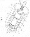
- FIG. 2 is a perspective view for illustrating an example of the damper body.
- the damper body 2 includes a fixed barrel 20, a screw shaft 30, a nut member 40, a bearing housing 50, a flywheel 60, and a rotary member 80.
- the fixed barrel 20 has a hollow portion, and is formed into a cylindrical shape.
- the screw shaft 30 is inserted into the hollow portion of the fixed barrel 20.
- the nut member 40 is threadedly engaged with the screw shaft 30 through intermediation of a large number of balls.
- the bearing housing 50 having a cylindrical shape is supported so as to be freely rotatable relative to the fixed barrel 20, and the nut member 40 is coupled to the bearing housing 50.
- the flywheel 60 having a cylindrical shape is fixed to the bearing housing 50.
- the rotary member 80 is supported so as to be freely rotatable relative to the fixed barrel 20, and is coupled to the flywheel 60.
- the fixed barrel 20 is coupled to the second coupling portion 11 through intermediation of a ball joint 21.
- the ball joint 21 stops rotation of the fixed barrel 20 about the center axis while absorbing angular displacement of the center axis of the fixed barrel 20 with respect to the second structure.
- the torque limiting member 3 is also coupled to the first coupling portion 10 through intermediation of a similar ball joint.
- a bearing (not shown) is provided between the fixed barrel 20 and the bearing housing 50, and the bearing housing 50 is supported so as to be freely rotatable relative to the fixed barrel 20. Further, the nut member 40 is fixed to one axial end of the bearing housing 50. When the nut member 40 is rotated, the bearing housing 50 is rotated relative to the fixed barrel 20 together with the nut member 40.
- the screw shaft 30 and the nut member 40 form a so-called ball screw device.
- Spiral thread grooves are formed in an outer peripheral surface of the screw shaft at a predetermined lead, and the large number of balls incorporated in the nut member roll on the thread grooves.
- an axial linear motion and a rotary motion around the screw shaft can be mutually converted between the screw shaft 30 and the nut member 40.
- the nut member 40 When the axial linear motion is applied to the screw shaft 30, the nut member 40 generates the rotary motion around the screw shaft 30. Meanwhile, when the rotary motion is applied to the nut member 40, the screw shaft 30 generates the axial linear motion.
- An axial end of the screw shaft 30 is fixed to the first structure through intermediation of the torque limiting member 3.
- the nut member 40 is rotated around the screw shaft 30 correspondingly, and the rotation is transmitted to the bearing housing 50.
- a transmission shaft 32 described later is provided on one end of the screw shaft 30, which protrudes from the flywheel 60, and the transmission shaft 32 is inserted into the torque limiting member 3.
- the flywheel 60 having a cylindrical shape is provided on an outer side of the bearing housing 50.
- the flywheel 60 is fixed to the bearing housing 50 so as to be integrally rotated with the nut member 40 and the bearing housing 50. Further, the bearing housing 50 is freely rotatable relative to the fixed barrel 20, and thus the flywheel 60 is also freely rotatable relative to the fixed barrel 20.
- the rotary member 80 is provided on a periphery of the fixed barrel 20.
- the rotary member 80 is supported to an outer peripheral surface of the fixed barrel 20 through intermediation of a rotary bearing, and is coupled to the flywheel 60 through intermediation of an end plate 61 so that the rotary member 80 is rotated around the fixed barrel 20 along with rotation of the flywheel 60.
- An inner peripheral surface of the rotary member 80 is opposed to the outer peripheral surface of the fixed barrel 20 through a small gap, and the gap is a sealed space for viscous fluid. Therefore, when the rotary member 80 is rotated, a shear resistance force is applied to the viscous fluid filled in the sealed space. Thus, energy of the rotary motion of the rotary member 80 as well as energy of the rotary motion of the flywheel 60 are damped.
- FIG. 3 is an illustration of an example of the torque limiting member 3.
- the torque limiting member 3 includes an outer cylinder member 31, the transmission shaft 32, a rotary bearing 33, and a plurality of friction members 34.
- the outer cylinder member 31 has a hollow portion, and is formed into a cylindrical shape.
- the transmission shaft 32 is inserted into the hollow portion of the outer cylinder member 31.
- the rotary bearing 33 is arranged in the hollow portion of the outer cylinder member 31, and retains the transmission shaft 32 in the hollow portion.
- the plurality of friction members 34 are pressed against the transmission shaft 32 to stop rotation of the transmission shaft 32 relative to the outer cylinder member 31.
- a coupling shaft 36 is fixed to the center of the lid member 35.
- a ball stud is integrally provided on a distal end of the coupling shaft 36. The ball stud is engaged with the first coupling portion 10 through intermediation of a ball joint, and absorbs angular displacement of the rotary inertia mass damper 1 with respect to the first structure.
- the transmission shaft 32 is inserted into the hollow portion of the outer cylinder member 31.
- the transmission shaft is rotated integrally with the screw shaft 30 to transmit a rotational torque, and an axial load (axial force) is transmitted between the transmission shaft and the screw shaft.
- the transmission shaft may be formed integrally with the screw shaft, or may be coupled to the screw shaft through intermediation of a joint.
- a pair of double-row roller bearings are used as the rotary bearing 33.
- Each of the double-row roller bearings is a so-called angular contact bearing, and has two roller rows in which rotation axes thereof are crossed each other at an angle of 90°.
- the rotation axes of rollers of the respective roller rows are inclined with respect to the axial direction of the transmission shaft 32 at an angle of 45°. With this, a high axial load can be transmitted between the outer cylinder member 31 and the transmission shaft 32.
- the plurality of friction members 34 are arranged between the outer cylinder member 31 and the transmission shaft 32 so as to surround the transmission shaft 32, and are held in contact with a flange portion 37 protruding from an outer peripheral surface of the transmission shaft 32.
- the friction members 34 are arranged so as to be immovable in a circumferential direction of the outer cylinder member 31 and to be movable in a radial direction.
- a plurality of adjustment screws 38 are threadedly engaged with the outer cylinder member 31. When the adjustment screws 38 are fastened, the friction members 34 advance toward the flange portion 37 of the transmission shaft 32 so that a pressing force of the friction members 34 against the flange portion 37 can be adjusted. That is, a friction force in accordance with the fastening degree of the adjustment screws 38 is applied between the friction members 34 and the flange portion 37, and the friction members 34 function as a brake shoe for stopping the rotation of the transmission shaft 32.
- the torque limiting member 3 functions as a torque limiter.
- the rotational torque applied to the transmission shaft in other words, the rotational torque applied to the screw shaft is equal to or lower than a limit torque set by the fastening of the adjustment screws, the transmission shaft 32 and the screw shaft 30 are retained without being rotated relative to the outer cylinder member 31.
- the rotational torque applied to the screw shaft 30 is higher than the limit torque set by the fastening of the adjustment screws 38, the transmission shaft 32 and the screw shaft 30 are rotated relative to the outer cylinder member 31.
- a rotational torque is generated due to the angular acceleration " ⁇ ".
- the rotational torque T is expressed by Expression (2) described below.
- "I” represents an inertial moment of the rotary body including the nut member 40, the bearing housing 50, and the flywheel 60.
- ⁇ 2 ⁇ / L 0 ⁇ a
- the axial inertia force Q is proportional to the reciprocal of the square of the lead L 0 of the screw shaft 30.
Landscapes
- Engineering & Computer Science (AREA)
- General Engineering & Computer Science (AREA)
- Architecture (AREA)
- Mechanical Engineering (AREA)
- Aviation & Aerospace Engineering (AREA)
- Acoustics & Sound (AREA)
- Physics & Mathematics (AREA)
- Emergency Management (AREA)
- Environmental & Geological Engineering (AREA)
- Business, Economics & Management (AREA)
- Structural Engineering (AREA)
- Civil Engineering (AREA)
- Vibration Prevention Devices (AREA)
- Buildings Adapted To Withstand Abnormal External Influences (AREA)
- Vibration Dampers (AREA)
Abstract
Description
- The present invention relates to a rotary inertia mass damper, which is to be mounted to a construction such as a building, and is configured to reduce vibration applied to the construction.
- As a rotary inertia mass damper, there has been known a rotary inertia mass damper disclosed in
Patent Literature 1. The rotary inertia mass damper includes a screw shaft, a nut member, an outer barrel, and an additional weight. The screw shaft has a spiral male thread, and one end thereof is fixed to a construction. The nut member is threadedly engaged with the screw shaft. The outer barrel supports the nut member so as to be freely rotatable, and is fixed to the construction. Rotation is applied to the additional weight by the nut member. - When relative vibration generated in the construction due to an earthquake or the like is input between the screw shaft and the outer barrel, axial acceleration is caused in the screw shaft due to the vibration, and the axial acceleration is converted into angular acceleration of the nut member threadedly engaged with the screw shaft. The angular acceleration is transmitted to the additional weight mounted to the nut member so that the nut member and the additional weight are rotated. The nut member and the additional weight integrally construct a rotary body, and a rotational torque generated in the rotary body is expressed by a product of an inertial moment of the rotary body and the angular acceleration. The rotational torque is reversely converted by the nut member and the screw shaft each time the axial acceleration of the screw shaft is reversed, and is applied to the screw shaft as an axial reaction force.
- As described above, when a ball screw device in which the nut member is threadedly engaged with the screw shaft is used, and the vibration applied to the construction is converted into a rotary motion of the rotary body, the axial acceleration of the screw shaft is amplified with an amplification factor in accordance with a lead of the male thread of the screw shaft when the axial acceleration of the screw shaft is converted into the angular acceleration of the nut member. Further, also when the rotational torque generated in the rotary body is reversely converted into the axial reaction force of the screw shaft, the rotational torque is amplified with an amplification factor in accordance with the lead of the male thread. Therefore, in the rotary inertia mass damper, even when the mass of the rotary body is small, a large reaction force can be applied to the screw shaft. Thus, a significant vibration damping effect can be obtained while attaining downsizing of the device.
- Meanwhile, the rotational torque generated in the rotary body is expressed by the product of the inertial moment of the rotary body and the angular acceleration. Thus, when excessive axial acceleration is input from the construction to the screw shaft, and is amplified so that excessive angular acceleration is generated in the nut member, the rotational torque generated in the rotary body also becomes excessive. Therefore, when the rotational torque is reversely converted into the axial reaction force of the screw shaft as it is, there is a fear in that the screw shaft or the nut member may be broken. Further, even though the screw shaft and the nut member are not broken, when the excessive axial reaction force is applied from the rotary inertia mass damper to the construction, there is also a fear in that the construction may be broken by the axial reaction force.
- In this regard, in the rotary inertia mass damper disclosed in
Patent Literature 1, friction members are provided between the nut member and the additional weight, and an upper limit value is set for the rotational torque transmitted between the nut member and the additional weight. Therefore, when the rotational torque transmitted between the nut member and the additional weight exceeds the upper limit value set for the friction members, the additional weight is separated from the nut member, and the inertial moment of the rotary body is generated only by the nut member. With this, the rotational torque reversely converted into the axial reaction force of the screw shaft is suppressed, thereby preventing the excessive axial reaction force from being applied to the screw shaft. - [PTL 1]
JP 2011-144831 A - However, in the rotary inertia mass damper disclosed in
Patent Literature 1, the friction members are provided between the nut member and the additional weight. Thus, even when the friction members slide so that the additional weight and the nut member are separated from each other, the nut member itself is rotated at angular acceleration obtained by amplifying the axial acceleration of the screw shaft. Therefore, the inertial moment of the rotary body is generated only by the nut member. However, when the excessive axial acceleration is input to the screw shaft, the excessive axial acceleration is amplified so that a high rotational torque is generated in the nut member. The rotational torque is reversely converted so that a large axial reaction force may be generated. Thus, there is a fear in that the construction may be broken by the axial reaction force. - The present invention has been made in view of the problems described above, and has an object to provide a rotary inertiamass damper, which is capable of suppressing an axial reaction force that is generated as a result of input of vibration having an excessive acceleration to the extent possible, thereby being capable of preventing breakage of the damper itself or a construction.
- That is, according to one embodiment of the present invention, it is premised that a rotary inertia mass damper includes: a first coupling portion, which is fixed to a first structure; a second coupling portion, which is coupled to a second structure; a screw shaft, which has a spiral thread groove formed in an outer peripheral surface of the screw shaft at a predetermined lead, and has one axial end connected to the first coupling portion and retained so as to be non-rotatable; a fixed barrel, which has a hollow portion for receiving the screw shaft, and is connected to the second coupling portion; and a rotary body, which is retained so as to be freely rotatable relative to the fixed barrel, is threadedly engaged with the screw shaft, and is configured to reciprocally rotate in accordance with advancing and retreating movement of the screw shaft relative to the fixed barrel, the rotary inertia mass damper being configured to damp vibration energy applied between the first structure and the second structure by imparting a rotation angle, which is uniquely determined by a change in distance between the first coupling portion and the second coupling portion and the lead of the screw shaft, to the rotary body. The rotary inertia mass damper further includes a torque limiting member, which is provided between the axial end of the screw shaft and the first coupling portion, and is configured to, when a rotational torque that exceeds a predetermined value is applied to the screw shaft, allow rotation of the screw shaft relative to the first coupling portion to reduce a rotation angle of the rotary body.
- According to the present invention, when the rotational torque that exceeds the predetermined value is applied to the screw shaft due to the vibration applied between the first structure and the second structure, the torque limiting member provided between the first coupling portion and the axial end of the screw shaft functions so as to cause rotation of the screw shaft, thereby causing pseudo increase in lead of the male thread grooves formed in the screw shaft. With this, the angular acceleration generated in the rotary body can be reduced, and the axial reaction force, which is generated due to the input vibration, can be reduced, thereby being capable of preventing breakage of the damper itself or the construction.
-
-
FIG. 1 is a schematic view for illustrating an example of a rotary inertia mass damper according to the present invention. -
FIG. 2 is a perspective view for illustrating an example of a damper body of the rotary inertia mass damper. -
FIG. 3 is a perspective view for illustrating an example of a torque limiting member of the rotary inertia mass damper. - Now, a rotary inertia mass damper according to the present invention is described in detail with reference to the attached drawings.
-
FIG. 1 is an illustration of an example of a rotary inertia mass damper to which the present invention is applied. The rotaryinertia mass damper 1 includes a first coupling portion 10 and asecond coupling portion 11 to be fixed to different portions (a first structure and a second structure) in a system including a construction such as a building, a tower, or a bridge. The system including the construction encompasses a foundation ground to which the construction is fixed. For example, the system including the construction includes a case in which a damping apparatus is arranged in an inside of the construction, and also a case in which the first coupling portion 10 is fixed to the construction and thesecond coupling portion 11 is fixed to the foundation ground. - When the construction vibrates, axial relative displacement is caused between the first coupling portion 10 and the
second coupling portion 11 fixed to the different portions in the system including the construction. The rotaryinertia mass damper 1 according to the present invention is configured to convert the relative displacement into a rotary motion of a flywheel through intermediation of a screw conversion mechanism including a screw shaft and a nut member. A rotational torque generated in a rotary body including the flywheel and the nut member is reversely converted into an axial reaction force of the screw shaft through intermediation of the screw conversion mechanism, and vibration energy causing the relative displacement is damped by the axial reaction force. - The rotary
inertia mass damper 1 roughly includes adamper body 2 and atorque limiting member 3 coupled in series to thedamper body 2. Thetorque limiting member 3 is provided between thedamper body 2 and the first coupling portion 10, and thedamper body 2 is provided between thetorque limiting member 3 and thesecond coupling portion 11. -
FIG. 2 is a perspective view for illustrating an example of the damper body. Thedamper body 2 includes a fixedbarrel 20, ascrew shaft 30, anut member 40, a bearinghousing 50, aflywheel 60, and arotary member 80. The fixedbarrel 20 has a hollow portion, and is formed into a cylindrical shape. Thescrew shaft 30 is inserted into the hollow portion of the fixedbarrel 20. Thenut member 40 is threadedly engaged with thescrew shaft 30 through intermediation of a large number of balls. The bearinghousing 50 having a cylindrical shape is supported so as to be freely rotatable relative to the fixedbarrel 20, and thenut member 40 is coupled to the bearinghousing 50. Theflywheel 60 having a cylindrical shape is fixed to the bearinghousing 50. Therotary member 80 is supported so as to be freely rotatable relative to the fixedbarrel 20, and is coupled to theflywheel 60. - The fixed
barrel 20 is coupled to thesecond coupling portion 11 through intermediation of aball joint 21. Theball joint 21 stops rotation of thefixed barrel 20 about the center axis while absorbing angular displacement of the center axis of the fixedbarrel 20 with respect to the second structure. Further, thetorque limiting member 3 is also coupled to the first coupling portion 10 through intermediation of a similar ball joint. - A bearing (not shown) is provided between the fixed
barrel 20 and the bearinghousing 50, and the bearinghousing 50 is supported so as to be freely rotatable relative to the fixedbarrel 20. Further, thenut member 40 is fixed to one axial end of the bearinghousing 50. When thenut member 40 is rotated, the bearinghousing 50 is rotated relative to the fixedbarrel 20 together with thenut member 40. - The
screw shaft 30 and thenut member 40 form a so-called ball screw device. Spiral thread grooves are formed in an outer peripheral surface of the screw shaft at a predetermined lead, and the large number of balls incorporated in the nut member roll on the thread grooves. With this, an axial linear motion and a rotary motion around the screw shaft can be mutually converted between thescrew shaft 30 and thenut member 40. When the axial linear motion is applied to thescrew shaft 30, thenut member 40 generates the rotary motion around thescrew shaft 30. Meanwhile, when the rotary motion is applied to thenut member 40, thescrew shaft 30 generates the axial linear motion. - An axial end of the
screw shaft 30 is fixed to the first structure through intermediation of thetorque limiting member 3. When relative displacement is caused between the first coupling portion 10 and thesecond coupling portion 11 by an earthquake or the like so that thescrew shaft 30 generates an axial linear motion, thenut member 40 is rotated around thescrew shaft 30 correspondingly, and the rotation is transmitted to the bearinghousing 50. Atransmission shaft 32 described later is provided on one end of thescrew shaft 30, which protrudes from theflywheel 60, and thetransmission shaft 32 is inserted into thetorque limiting member 3. - The
flywheel 60 having a cylindrical shape is provided on an outer side of the bearinghousing 50. Theflywheel 60 is fixed to the bearinghousing 50 so as to be integrally rotated with thenut member 40 and the bearinghousing 50. Further, the bearinghousing 50 is freely rotatable relative to the fixedbarrel 20, and thus theflywheel 60 is also freely rotatable relative to the fixedbarrel 20. - Meanwhile, the
rotary member 80 is provided on a periphery of the fixedbarrel 20. Therotary member 80 is supported to an outer peripheral surface of the fixedbarrel 20 through intermediation of a rotary bearing, and is coupled to theflywheel 60 through intermediation of anend plate 61 so that therotary member 80 is rotated around the fixedbarrel 20 along with rotation of theflywheel 60. - An inner peripheral surface of the
rotary member 80 is opposed to the outer peripheral surface of the fixedbarrel 20 through a small gap, and the gap is a sealed space for viscous fluid. Therefore, when therotary member 80 is rotated, a shear resistance force is applied to the viscous fluid filled in the sealed space. Thus, energy of the rotary motion of therotary member 80 as well as energy of the rotary motion of theflywheel 60 are damped. -
FIG. 3 is an illustration of an example of thetorque limiting member 3. Thetorque limiting member 3 includes anouter cylinder member 31, thetransmission shaft 32, arotary bearing 33, and a plurality offriction members 34. Theouter cylinder member 31 has a hollow portion, and is formed into a cylindrical shape. Thetransmission shaft 32 is inserted into the hollow portion of theouter cylinder member 31. Therotary bearing 33 is arranged in the hollow portion of theouter cylinder member 31, and retains thetransmission shaft 32 in the hollow portion. The plurality offriction members 34 are pressed against thetransmission shaft 32 to stop rotation of thetransmission shaft 32 relative to theouter cylinder member 31. - One axial end of the hollow portion formed in the
outer cylinder member 31 is closed by alid member 35. Acoupling shaft 36 is fixed to the center of thelid member 35. Although not illustrated inFIG. 3 , a ball stud is integrally provided on a distal end of thecoupling shaft 36. The ball stud is engaged with the first coupling portion 10 through intermediation of a ball joint, and absorbs angular displacement of the rotaryinertia mass damper 1 with respect to the first structure. - The
transmission shaft 32 is inserted into the hollow portion of theouter cylinder member 31. The transmission shaft is rotated integrally with thescrew shaft 30 to transmit a rotational torque, and an axial load (axial force) is transmitted between the transmission shaft and the screw shaft. The transmission shaft may be formed integrally with the screw shaft, or may be coupled to the screw shaft through intermediation of a joint. In order to retain thetransmission shaft 32 so as to be freely rotatable relative to theouter cylinder member 31 while bearing a radial load and a thrust load applied between theouter cylinder member 31 and thetransmission shaft 32, a pair of double-row roller bearings are used as therotary bearing 33. Each of the double-row roller bearings is a so-called angular contact bearing, and has two roller rows in which rotation axes thereof are crossed each other at an angle of 90°. The rotation axes of rollers of the respective roller rows are inclined with respect to the axial direction of thetransmission shaft 32 at an angle of 45°. With this, a high axial load can be transmitted between theouter cylinder member 31 and thetransmission shaft 32. - Further, the plurality of
friction members 34 are arranged between theouter cylinder member 31 and thetransmission shaft 32 so as to surround thetransmission shaft 32, and are held in contact with aflange portion 37 protruding from an outer peripheral surface of thetransmission shaft 32. Thefriction members 34 are arranged so as to be immovable in a circumferential direction of theouter cylinder member 31 and to be movable in a radial direction. A plurality of adjustment screws 38 are threadedly engaged with theouter cylinder member 31. When the adjustment screws 38 are fastened, thefriction members 34 advance toward theflange portion 37 of thetransmission shaft 32 so that a pressing force of thefriction members 34 against theflange portion 37 can be adjusted. That is, a friction force in accordance with the fastening degree of the adjustment screws 38 is applied between thefriction members 34 and theflange portion 37, and thefriction members 34 function as a brake shoe for stopping the rotation of thetransmission shaft 32. - Therefore, assuming a state in which a rotational torque is applied to the
transmission shaft 32, when a friction force generated between theflange portion 37 and thefriction members 34 is large enough to retain thetransmission shaft 32 so as to be non-rotatable against the rotational torque, the transmission shaft is retained so as to be non-rotatable relative to theouter cylinder member 31. Conversely, when the friction force generated between theflange portion 37 and thefriction members 34 is small, the friction force cannot stop the rotation of thetransmission shaft 32 against the rotational torque so that thetransmission shaft 32 may be rotated relative to theouter cylinder member 31. - That is, the
torque limiting member 3 functions as a torque limiter. When the rotational torque applied to the transmission shaft, in other words, the rotational torque applied to the screw shaft is equal to or lower than a limit torque set by the fastening of the adjustment screws, thetransmission shaft 32 and thescrew shaft 30 are retained without being rotated relative to theouter cylinder member 31. Meanwhile, when the rotational torque applied to thescrew shaft 30 is higher than the limit torque set by the fastening of the adjustment screws 38, thetransmission shaft 32 and thescrew shaft 30 are rotated relative to theouter cylinder member 31. - In the rotary
inertia mass damper 1 having the configuration described above, when relative vibration is applied between the first coupling portion 10 and thesecond coupling portion 11, the axial load is transmitted between thetorque limiting member 3 and thescrew shaft 30. Thus, the axial acceleration is imparted to thescrew shaft 30, and the vibration causes an axial linear motion of thescrew shaft 30 relative to the fixedbarrel 20. In this case, axial acceleration "a", which is imparted to thescrew shaft 30, is converted into angular acceleration "α" of thenut member 40 by Expression (1) described below. In Expression (1), L0 represents the lead of the thread grooves formed in thescrew shaft 30. Further, in the rotary body integrally including thenut member 40, the bearinghousing 50, and theflywheel 60, a rotational torque is generated due to the angular acceleration "α". The rotational torque T is expressed by Expression (2) described below. In Expression (2), "I" represents an inertial moment of the rotary body including thenut member 40, the bearinghousing 50, and theflywheel 60.

- The rotational torque T generated in the rotary body is converted again by the
nut member 40 into an axial inertia force Q. The axial inertia force Q is expressed by Expression (3) described below.
- As expressed in Expression (3), the axial inertia force Q can be considered as a product of the mass M=(2n/L0)2×I, which is equivalent to the axial acceleration "a" in the axial direction, and the rotary
inertia mass damper 1 can be regarded as a damper having the equivalent mass M in the axial direction. - As understood from Expressions (1) to (3), as the inertial moment I of the rotary body is reduced, or the lead L0 of the
screw shaft 30 is increased, the mass M equivalent in the axial direction is reduced. Assuming that the axial acceleration, which is imparted to thescrew shaft 30, is constant, the rotational torque T applied to the rotary body and the axial reaction force applied to thescrew shaft 30 and the fixedbarrel 20 are reduced. - When the axial acceleration "a" is imparted to the
screw shaft 30 so that the rotational torque T is generated in the rotary body (thenut member 40, the bearinghousing 50, and the flywheel 60), as a counteraction, a reverse rotational torque as high as the rotational torque T is similarly applied to thescrew shaft 30. Thetransmission shaft 32 inserted into thetorque limiting member 3 is provided integrally with thescrew shaft 30, and thus the rotational torque T is applied as it is to thetransmission shaft 32 of thetorque limiting member 3. - When the
torque limiting member 3 as the torque limiter retains thetransmission shaft 32 so as to be non-rotatable against the rotational torque T, that is, when a linear motion is caused with respect to the fixedbarrel 20 without rotating thescrew shaft 30, an rotation angle in accordance with the lead of the thread grooves of thescrew shaft 30 is imparted to the rotary body. - In contrast, when the rotational torque T applied to the
screw shaft 30 is so high that thetorque limiting member 3 cannot retain thetransmission shaft 32 so as to be non-rotatable, that is, when thescrew shaft 30 is rotated relative to the fixedbarrel 20, thescrew shaft 30 performs an axial linear motion relative to the fixedbarrel 20 while being rotated relative to thenut member 40. At this time, even when the axial movement amount of the screw shaft is the same, the rotation angle of thenut member 40 is reduced as compared to a case in which thescrew shaft 30 is retained so as to be non-rotatable, and pseudo increase in lead L0 of thescrew shaft 30 occurs. - That is, in the rotary
inertia mass damper 1 according to the first embodiment, in a case in which a rotational torque that exceeds the limit torque set in thetorque limiting member 3 is applied to thescrew shaft 30, when the screw shaft is rotated, the pseudo increase in lead L0 of the screw shaft occurs, thereby reducing the rotational torque T and the axial inertia force Q. In particular, as expressed in Expression (3), the axial inertia force Q is proportional to the reciprocal of the square of the lead L0 of thescrew shaft 30. Thus, when the lead L0 is increased, the axial inertia force Q is significantly reduced. - Therefore, in a case in which a construction to which the rotary
inertia mass damper 1 is mounted vibrates due to a massive earthquake or the like, and axial displacement with the excessive acceleration is caused between the first coupling portion 10 and thesecond coupling portion 11, when thescrew shaft 30 is rotated, the rotational torque T applied to the rotary body is suppressed within a range of the limit torque set in thetorque limiting member 3. As a result, the axial reaction force, which is applied from the rotary inertia mass damper to the construction, is also reduced.
Claims (2)
- A rotary inertia mass damper, comprising:a first coupling portion (10), which is fixed to a first structure;a second coupling portion (11), which is coupled to a second structure;a screw shaft (30), which has a spiral thread groove formed in an outer peripheral surface of the screw shaft at a predetermined lead, and has one axial end connected to the first coupling portion and retained so as to be non-rotatable;a fixed barrel (20), which has a hollow portion for receiving the screw shaft, and is connected to the second coupling portion; anda rotary body (40, 50, 60), which is retained so as to be freely rotatable relative to the fixed barrel (20), is threadedly engaged with the screw shaft (30), and is configured to reciprocally rotate in accordance with advancing and retreating movement of the screw shaft (30) relative to the fixed barrel (20),the rotary inertia mass damper being configured to damp vibration energy applied between the first structure and the second structure by imparting a rotation angle, which is uniquely determined by a change in distance between the first coupling portion (10) and the second coupling portion (11) and the lead of the screw shaft (30), to the rotary body,the rotary inertia mass damper further comprising a torque limiting member (3), which is provided between an axial end of the screwshaft (30) and the first couplingportion (10), and is configured to, when a rotational torque that exceeds a predetermined value is applied to the screw shaft (30), allow rotation of the screw shaft (30) relative to the first coupling portion (10) to reduce a rotation angle of the rotary body (40, 50, 60).
- The rotary inertia mass damper according to claim 1,
wherein the torque limiting member (3) includes:a coupling shaft (36), which is connected to the first coupling portion (10) so as to be non-rotatable;a transmission shaft (32), which is retained to the coupling shaft (36) so as to be freely rotatable, and is retained to the screw shaft (30) so as to be non-rotatable; andfriction members (34), which are held in pressure-contact with the transmission shaft (32) to stop rotation of the transmission shaft (32) relative to the coupling shaft (36),wherein the rotary bearing (33) configured to retain the transmission shaft (32) so as to be freely rotatable has two roller rows in which rotation axes of rollers are cross each other at an angle of 90°, the rotation axes of the rollers of the respective roller rows being inclined with respect to an axial direction of the transmission shaft (32) at an angle of 45°.
Applications Claiming Priority (2)
| Application Number | Priority Date | Filing Date | Title |
|---|---|---|---|
| JP2015212777A JP6580457B2 (en) | 2015-10-29 | 2015-10-29 | Rotating inertia mass damper |
| PCT/JP2016/080908 WO2017073420A1 (en) | 2015-10-29 | 2016-10-19 | Rotary inertia mass damper |
Publications (2)
| Publication Number | Publication Date |
|---|---|
| EP3369961A1 true EP3369961A1 (en) | 2018-09-05 |
| EP3369961A4 EP3369961A4 (en) | 2018-11-14 |
Family
ID=58630145
Family Applications (1)
| Application Number | Title | Priority Date | Filing Date |
|---|---|---|---|
| EP16859650.0A Withdrawn EP3369961A4 (en) | 2015-10-29 | 2016-10-19 | Rotary inertia mass damper |
Country Status (6)
| Country | Link |
|---|---|
| US (1) | US10508439B2 (en) |
| EP (1) | EP3369961A4 (en) |
| JP (1) | JP6580457B2 (en) |
| CN (1) | CN108138894B (en) |
| TW (1) | TWI703283B (en) |
| WO (1) | WO2017073420A1 (en) |
Families Citing this family (15)
| Publication number | Priority date | Publication date | Assignee | Title |
|---|---|---|---|---|
| JP7076899B2 (en) * | 2018-02-20 | 2022-05-30 | Thk株式会社 | Spherical joint and damping device using this |
| JP7090437B2 (en) * | 2018-03-16 | 2022-06-24 | 清水建設株式会社 | Spherical joint and damping device using this |
| EP3599162B1 (en) * | 2018-07-27 | 2020-11-11 | LEONARDO S.p.A. | Helicopter kit |
| TWI671163B (en) * | 2019-01-30 | 2019-09-11 | 優鋼機械股份有限公司 | Inertial rotation device |
| CN110528947A (en) * | 2019-07-23 | 2019-12-03 | 同济大学 | Inner/outer tube self-balancing type is used to hold damper |
| CN110847404B (en) * | 2019-11-26 | 2021-04-27 | 西安建筑科技大学 | A replaceable X-type mild steel composite energy dissipation damper |
| CN111236724B (en) * | 2020-01-20 | 2022-01-11 | 同济大学 | Assembled sleeve metal round bar energy dissipation damper |
| CN111963607B (en) * | 2020-09-07 | 2024-06-25 | 成都市新筑交通科技有限公司 | Rotary friction damper |
| TWI766449B (en) | 2020-11-25 | 2022-06-01 | 國立臺灣科技大學 | Active inerter damper |
| CN112982704B (en) * | 2021-02-08 | 2022-05-31 | 同济大学 | Series-parallel tuned inertial damper |
| CN113459277B (en) * | 2021-07-01 | 2022-07-01 | 中建中新建设工程有限公司 | Grouting device and grouting method for pile foundation construction |
| CN114033832B (en) * | 2021-11-05 | 2023-03-28 | 兰州理工大学 | Two-dimensional integrated semi-active vibration control device based on impact vibration reduction |
| CN114517822A (en) * | 2022-02-14 | 2022-05-20 | 中国海洋大学 | Vibrator and control method thereof |
| CN115749032B (en) * | 2022-12-05 | 2024-05-24 | 重庆交通大学 | Displacement and acceleration grading double-control hybrid damper |
| CN116434988A (en) * | 2023-03-24 | 2023-07-14 | 华能核能技术研究院有限公司 | Pebble bed high temperature stacking device |
Family Cites Families (23)
| Publication number | Priority date | Publication date | Assignee | Title |
|---|---|---|---|---|
| JPS5551146A (en) * | 1978-10-06 | 1980-04-14 | Nhk Spring Co Ltd | Vibration control device |
| US4407395A (en) * | 1981-09-25 | 1983-10-04 | Suozzo Leonard S | Mechanical shock and sway arrestor |
| US4431093A (en) * | 1982-03-11 | 1984-02-14 | Pacific Scientific Company | Motion snubber |
| US4536114A (en) * | 1983-07-01 | 1985-08-20 | The United States Of America As Represented By The Administrator Of The National Aeronautics And Space Administration | Variable length strut with longitudinal compliance and locking capability |
| NZ235423A (en) * | 1989-10-18 | 1995-04-27 | Mitsubishi Heavy Ind Ltd | Dynamic damper which absorbs building vibration in any horizontal direction |
| US6230450B1 (en) * | 1996-12-27 | 2001-05-15 | Sumitomo Construction Co., Ltd. | Damping top, damping rod, and damping device using same |
| TW571038B (en) * | 1999-09-14 | 2004-01-11 | Thk Co Ltd | Base isolation device with damping mechanism |
| US6510660B1 (en) * | 1999-11-08 | 2003-01-28 | Thk Co., Ltd. | Damping device |
| JP4633229B2 (en) * | 2000-05-31 | 2011-02-16 | Thk株式会社 | Damping device |
| JP2005009565A (en) * | 2003-06-18 | 2005-01-13 | Tokkyokiki Corp | Vibration damping apparatus |
| WO2008041545A1 (en) * | 2006-09-29 | 2008-04-10 | Thk Co., Ltd. | Damping device |
| WO2008121451A2 (en) * | 2007-02-16 | 2008-10-09 | Parker-Hannifin Corporation | Aircraft flight control actuation system with direct acting, force limiting, actuator |
| TW200918788A (en) * | 2007-10-26 | 2009-05-01 | Univ Nat Taiwan | Screw-type inerter mechanism |
| JP5040666B2 (en) * | 2008-01-15 | 2012-10-03 | 株式会社ジェイテクト | Ball screw device |
| JP5051590B2 (en) | 2008-07-10 | 2012-10-17 | 清水建設株式会社 | Inertia mass damper |
| JP2011144831A (en) | 2010-01-12 | 2011-07-28 | Shimizu Corp | Axial resistance type inertial mass damper |
| JP5521720B2 (en) | 2010-04-08 | 2014-06-18 | 株式会社大林組 | Damping structure of joint |
| JP5096551B2 (en) * | 2010-12-20 | 2012-12-12 | Thk株式会社 | Screw motion mechanism and damping device using the same |
| CN202280188U (en) * | 2011-10-11 | 2012-06-20 | 浙江精工钢结构有限公司 | Retractable roof vertical adjusting support |
| CN103874867B (en) * | 2011-10-19 | 2016-08-31 | Thk株式会社 | Attenuating device |
| JP5970818B2 (en) * | 2012-01-10 | 2016-08-17 | オイレス工業株式会社 | Seismic isolation mechanism |
| JP5945889B2 (en) | 2012-07-23 | 2016-07-05 | 清水建設株式会社 | Seismic isolation structure |
| JP5925672B2 (en) * | 2012-12-27 | 2016-05-25 | 株式会社構造計画研究所 | Damping device and structure damping device |
-
2015
- 2015-10-29 JP JP2015212777A patent/JP6580457B2/en active Active
-
2016
- 2016-10-19 WO PCT/JP2016/080908 patent/WO2017073420A1/en not_active Ceased
- 2016-10-19 EP EP16859650.0A patent/EP3369961A4/en not_active Withdrawn
- 2016-10-19 US US15/770,836 patent/US10508439B2/en active Active
- 2016-10-19 CN CN201680058924.4A patent/CN108138894B/en active Active
- 2016-10-26 TW TW105134577A patent/TWI703283B/en active
Also Published As
| Publication number | Publication date |
|---|---|
| TWI703283B (en) | 2020-09-01 |
| CN108138894B (en) | 2020-06-09 |
| TW201738479A (en) | 2017-11-01 |
| JP6580457B2 (en) | 2019-09-25 |
| WO2017073420A1 (en) | 2017-05-04 |
| JP2017082932A (en) | 2017-05-18 |
| US20180305922A1 (en) | 2018-10-25 |
| CN108138894A (en) | 2018-06-08 |
| US10508439B2 (en) | 2019-12-17 |
| EP3369961A4 (en) | 2018-11-14 |
Similar Documents
| Publication | Publication Date | Title |
|---|---|---|
| US10508439B2 (en) | Rotary inertia mass damper | |
| US9316297B2 (en) | Screw motion mechanism and damping apparatus using same | |
| US9494208B2 (en) | Damping device | |
| US4593574A (en) | Torque-dependent pressure mechanism for continuously adjustable ball-type planetary gear set | |
| JP5096536B2 (en) | Attenuator | |
| JP5915995B2 (en) | Rotating inertia mass damper | |
| CN104842372B (en) | Overload protection device for joint of humanoid robot | |
| JP2011144831A (en) | Axial resistance type inertial mass damper | |
| JP5861883B2 (en) | Rotating inertia mass damper and brace damper and brace frame | |
| WO2023026488A1 (en) | Strain wave gear device and actuator | |
| JP2012072867A (en) | Suspension device and vehicle incorporating suspension device | |
| JP2016050593A (en) | Seismic isolation damper | |
| JP5839282B2 (en) | Rotating inertia mass damper | |
| JP6520474B2 (en) | Rotary inertia mass damper | |
| JP2016203889A (en) | Constant velocity universal joint | |
| JP7121652B2 (en) | vibration damping device | |
| JP6143613B2 (en) | Anti-shake device | |
| CN107859198B (en) | Torsional composite metal energy-dissipation damper | |
| CN110989705B (en) | A constant torque controller | |
| RU2705637C1 (en) | Missile steering gear unit | |
| JP7076899B2 (en) | Spherical joint and damping device using this | |
| SU563529A1 (en) | Uniform load distributing device | |
| JP2018059579A (en) | Friction transmission device | |
| JP2019078320A (en) | Inertia mass damper |
Legal Events
| Date | Code | Title | Description |
|---|---|---|---|
| PUAI | Public reference made under article 153(3) epc to a published international application that has entered the european phase |
Free format text: ORIGINAL CODE: 0009012 |
|
| 17P | Request for examination filed |
Effective date: 20180524 |
|
| AK | Designated contracting states |
Kind code of ref document: A1 Designated state(s): AL AT BE BG CH CY CZ DE DK EE ES FI FR GB GR HR HU IE IS IT LI LT LU LV MC MK MT NL NO PL PT RO RS SE SI SK SM TR |
|
| AX | Request for extension of the european patent |
Extension state: BA ME |
|
| A4 | Supplementary search report drawn up and despatched |
Effective date: 20181017 |
|
| RIC1 | Information provided on ipc code assigned before grant |
Ipc: F16F 15/02 20060101ALI20181011BHEP Ipc: F16H 25/20 20060101ALN20181011BHEP Ipc: F16F 15/023 20060101ALI20181011BHEP Ipc: F16F 7/10 20060101AFI20181011BHEP Ipc: F16F 9/12 20060101ALN20181011BHEP Ipc: E04H 9/02 20060101ALI20181011BHEP |
|
| DAV | Request for validation of the european patent (deleted) | ||
| DAX | Request for extension of the european patent (deleted) | ||
| 17Q | First examination report despatched |
Effective date: 20190628 |
|
| STAA | Information on the status of an ep patent application or granted ep patent |
Free format text: STATUS: THE APPLICATION IS DEEMED TO BE WITHDRAWN |
|
| 18D | Application deemed to be withdrawn |
Effective date: 20200812 |