JP5925672B2 - Damping device and structure damping device - Google Patents
Damping device and structure damping device Download PDFInfo
- Publication number
- JP5925672B2 JP5925672B2 JP2012285165A JP2012285165A JP5925672B2 JP 5925672 B2 JP5925672 B2 JP 5925672B2 JP 2012285165 A JP2012285165 A JP 2012285165A JP 2012285165 A JP2012285165 A JP 2012285165A JP 5925672 B2 JP5925672 B2 JP 5925672B2
- Authority
- JP
- Japan
- Prior art keywords
- cylinder
- damping device
- magnetic field
- flywheel
- generator
- Prior art date
- Legal status (The legal status is an assumption and is not a legal conclusion. Google has not performed a legal analysis and makes no representation as to the accuracy of the status listed.)
- Active
Links
Images


Classifications
-
- E—FIXED CONSTRUCTIONS
- E04—BUILDING
- E04H—BUILDINGS OR LIKE STRUCTURES FOR PARTICULAR PURPOSES; SWIMMING OR SPLASH BATHS OR POOLS; MASTS; FENCING; TENTS OR CANOPIES, IN GENERAL
- E04H9/00—Buildings, groups of buildings or shelters adapted to withstand or provide protection against abnormal external influences, e.g. war-like action, earthquake or extreme climate
- E04H9/02—Buildings, groups of buildings or shelters adapted to withstand or provide protection against abnormal external influences, e.g. war-like action, earthquake or extreme climate withstanding earthquake or sinking of ground
- E04H9/021—Bearing, supporting or connecting constructions specially adapted for such buildings
- E04H9/0215—Bearing, supporting or connecting constructions specially adapted for such buildings involving active or passive dynamic mass damping systems
-
- E—FIXED CONSTRUCTIONS
- E04—BUILDING
- E04H—BUILDINGS OR LIKE STRUCTURES FOR PARTICULAR PURPOSES; SWIMMING OR SPLASH BATHS OR POOLS; MASTS; FENCING; TENTS OR CANOPIES, IN GENERAL
- E04H9/00—Buildings, groups of buildings or shelters adapted to withstand or provide protection against abnormal external influences, e.g. war-like action, earthquake or extreme climate
- E04H9/02—Buildings, groups of buildings or shelters adapted to withstand or provide protection against abnormal external influences, e.g. war-like action, earthquake or extreme climate withstanding earthquake or sinking of ground
- E04H9/021—Bearing, supporting or connecting constructions specially adapted for such buildings
- E04H9/0237—Structural braces with damping devices
-
- F—MECHANICAL ENGINEERING; LIGHTING; HEATING; WEAPONS; BLASTING
- F16—ENGINEERING ELEMENTS AND UNITS; GENERAL MEASURES FOR PRODUCING AND MAINTAINING EFFECTIVE FUNCTIONING OF MACHINES OR INSTALLATIONS; THERMAL INSULATION IN GENERAL
- F16F—SPRINGS; SHOCK-ABSORBERS; MEANS FOR DAMPING VIBRATION
- F16F15/00—Suppression of vibrations in systems; Means or arrangements for avoiding or reducing out-of-balance forces, e.g. due to motion
- F16F15/02—Suppression of vibrations of non-rotating, e.g. reciprocating systems; Suppression of vibrations of rotating systems by use of members not moving with the rotating systems
- F16F15/023—Suppression of vibrations of non-rotating, e.g. reciprocating systems; Suppression of vibrations of rotating systems by use of members not moving with the rotating systems using fluid means
- F16F15/027—Suppression of vibrations of non-rotating, e.g. reciprocating systems; Suppression of vibrations of rotating systems by use of members not moving with the rotating systems using fluid means comprising control arrangements
-
- F—MECHANICAL ENGINEERING; LIGHTING; HEATING; WEAPONS; BLASTING
- F16—ENGINEERING ELEMENTS AND UNITS; GENERAL MEASURES FOR PRODUCING AND MAINTAINING EFFECTIVE FUNCTIONING OF MACHINES OR INSTALLATIONS; THERMAL INSULATION IN GENERAL
- F16F—SPRINGS; SHOCK-ABSORBERS; MEANS FOR DAMPING VIBRATION
- F16F15/00—Suppression of vibrations in systems; Means or arrangements for avoiding or reducing out-of-balance forces, e.g. due to motion
- F16F15/02—Suppression of vibrations of non-rotating, e.g. reciprocating systems; Suppression of vibrations of rotating systems by use of members not moving with the rotating systems
- F16F15/03—Suppression of vibrations of non-rotating, e.g. reciprocating systems; Suppression of vibrations of rotating systems by use of members not moving with the rotating systems using magnetic or electromagnetic means
-
- F—MECHANICAL ENGINEERING; LIGHTING; HEATING; WEAPONS; BLASTING
- F16—ENGINEERING ELEMENTS AND UNITS; GENERAL MEASURES FOR PRODUCING AND MAINTAINING EFFECTIVE FUNCTIONING OF MACHINES OR INSTALLATIONS; THERMAL INSULATION IN GENERAL
- F16F—SPRINGS; SHOCK-ABSORBERS; MEANS FOR DAMPING VIBRATION
- F16F15/00—Suppression of vibrations in systems; Means or arrangements for avoiding or reducing out-of-balance forces, e.g. due to motion
- F16F15/30—Flywheels
-
- F—MECHANICAL ENGINEERING; LIGHTING; HEATING; WEAPONS; BLASTING
- F16—ENGINEERING ELEMENTS AND UNITS; GENERAL MEASURES FOR PRODUCING AND MAINTAINING EFFECTIVE FUNCTIONING OF MACHINES OR INSTALLATIONS; THERMAL INSULATION IN GENERAL
- F16F—SPRINGS; SHOCK-ABSORBERS; MEANS FOR DAMPING VIBRATION
- F16F9/00—Springs, vibration-dampers, shock-absorbers, or similarly-constructed movement-dampers using a fluid or the equivalent as damping medium
- F16F9/10—Springs, vibration-dampers, shock-absorbers, or similarly-constructed movement-dampers using a fluid or the equivalent as damping medium using liquid only; using a fluid of which the nature is immaterial
- F16F9/12—Devices with one or more rotary vanes turning in the fluid any throttling effect being immaterial, i.e. damping by viscous shear effect only
-
- F—MECHANICAL ENGINEERING; LIGHTING; HEATING; WEAPONS; BLASTING
- F16—ENGINEERING ELEMENTS AND UNITS; GENERAL MEASURES FOR PRODUCING AND MAINTAINING EFFECTIVE FUNCTIONING OF MACHINES OR INSTALLATIONS; THERMAL INSULATION IN GENERAL
- F16F—SPRINGS; SHOCK-ABSORBERS; MEANS FOR DAMPING VIBRATION
- F16F9/00—Springs, vibration-dampers, shock-absorbers, or similarly-constructed movement-dampers using a fluid or the equivalent as damping medium
- F16F9/32—Details
- F16F9/53—Means for adjusting damping characteristics by varying fluid viscosity, e.g. electromagnetically
- F16F9/535—Magnetorheological [MR] fluid dampers
-
- E—FIXED CONSTRUCTIONS
- E04—BUILDING
- E04H—BUILDINGS OR LIKE STRUCTURES FOR PARTICULAR PURPOSES; SWIMMING OR SPLASH BATHS OR POOLS; MASTS; FENCING; TENTS OR CANOPIES, IN GENERAL
- E04H9/00—Buildings, groups of buildings or shelters adapted to withstand or provide protection against abnormal external influences, e.g. war-like action, earthquake or extreme climate
- E04H9/02—Buildings, groups of buildings or shelters adapted to withstand or provide protection against abnormal external influences, e.g. war-like action, earthquake or extreme climate withstanding earthquake or sinking of ground
- E04H9/028—Earthquake withstanding shelters
-
- F—MECHANICAL ENGINEERING; LIGHTING; HEATING; WEAPONS; BLASTING
- F16—ENGINEERING ELEMENTS AND UNITS; GENERAL MEASURES FOR PRODUCING AND MAINTAINING EFFECTIVE FUNCTIONING OF MACHINES OR INSTALLATIONS; THERMAL INSULATION IN GENERAL
- F16F—SPRINGS; SHOCK-ABSORBERS; MEANS FOR DAMPING VIBRATION
- F16F2232/00—Nature of movement
- F16F2232/06—Translation-to-rotary conversion
-
- F—MECHANICAL ENGINEERING; LIGHTING; HEATING; WEAPONS; BLASTING
- F16—ENGINEERING ELEMENTS AND UNITS; GENERAL MEASURES FOR PRODUCING AND MAINTAINING EFFECTIVE FUNCTIONING OF MACHINES OR INSTALLATIONS; THERMAL INSULATION IN GENERAL
- F16H—GEARING
- F16H25/00—Gearings comprising primarily only cams, cam-followers and screw-and-nut mechanisms
- F16H25/18—Gearings comprising primarily only cams, cam-followers and screw-and-nut mechanisms for conveying or interconverting oscillating or reciprocating motions
- F16H25/20—Screw mechanisms
Description
本発明は、減衰装置及び構造物の制振装置に関し、更に詳しくは直進運動を回転運動に変換するボールねじ及びボールナットによって回転駆動されるフライホイールの慣性モーメントと、磁気粘性流体の粘性抵抗を利用した減衰装置、及びこれを用いた構造物の制振装置に関する。 The present invention relates to a damping device and a structure damping device. More specifically, the present invention relates to a moment of inertia of a flywheel that is rotated by a ball screw and a ball nut that converts a linear motion into a rotational motion, and a viscous resistance of a magnetorheological fluid. The present invention relates to a damping device used and a structure damping device using the same.
建築構造物や各種機械装置における振動の伝達を抑制する装置として、物体の慣性を利用した制振装置が提案されている。このような制振装置として、小型化を図るために直線運動をフライホイールの回転運動に変換する機構を用い、回転するフライホイールの慣性モーメントを制振に利用するものがある。
特許文献1及び特許文献2には、ボールねじとボールナットとを使用して直線運動を回転運動に変換して、ケース内に配置したフライホイールを回転させるとともに、このフライホイールとケースとの間に例えば合成ゴム等の粘性体を配置したものが記載されている(段落0060、図6参照)。
このような制振装置によれば、ボールねじとボールナットとの組合せによって、微少な並進運動を増幅してフライホイールを高速で回転させて、このフライホイールの慣性モーメントと、フライホイールとケースとの間の粘性抵抗とを制振に利用することができる。
As a device for suppressing vibration transmission in a building structure or various mechanical devices, a vibration damping device using the inertia of an object has been proposed. As such a vibration damping device, there is a device that uses a mechanism that converts linear motion into rotational motion of a flywheel in order to reduce the size, and uses the inertia moment of the rotating flywheel for vibration damping.
In Patent Document 1 and
According to such a vibration damping device, a combination of a ball screw and a ball nut amplifies a minute translational motion and rotates the flywheel at high speed, and the inertial moment of the flywheel, the flywheel and the case, The viscous resistance between the two can be used for damping.
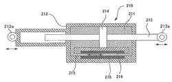
また、減衰装置として、磁気粘性流体(MR流体)の粘性や摩擦を減衰に利用したものが提案されている。特許文献3には、磁気粘性流体を使用した減衰装置が記載されている。図13は従来の減衰装置の概略構成を示す断面図である。減衰装置210は、磁気粘性流体211を満たしたシリンダー212と、シリンダー212内に挿通されて軸方向へ進退自在に支持されたピストンロッド213と、ピストンロッド213の中間部適所に固定されシリンダー212内を仕切るピストン214と、シリンダー212の下部に設けられたバイパス管215と、バイパス管215の軸方向に沿って配置された電磁石等の磁界形成手段216と、を備える。シリンダー212の端部とピストンロッド213の端部には夫々取付部212a、213aが設けられ、各取付部は例えば建造物の異なった部位に取り付けられる。
建造物が地震等によって振動した場合、ピストン214がシリンダー内を軸方向へ移動することにより磁気粘性流体211を付勢し、磁気粘性流体がバイパス管215内を流動する。この際、磁気粘性流体211の磁性体粒子が磁界形成手段216の磁界を受けて鎖状につながることにより磁気粘性流体211の流れに抵抗を生じさせて、前記振動を減衰させる。
このような減衰装置210によれば、磁界形成手段である電磁石への電流を制御することにより、磁気粘性流体211による減衰特性を調整し、減衰装置210の減衰特性を変化させることができる。
Further, as a damping device, a device using the viscosity or friction of a magnetorheological fluid (MR fluid) for damping has been proposed. Patent Document 3 describes a damping device using a magnetorheological fluid. FIG. 13 is a cross-sectional view showing a schematic configuration of a conventional damping device. The
When the building vibrates due to an earthquake or the like, the
According to such an
しかしながら、上述した特許文献1及び特許文献2に記載の制振装置は、加振源からの振動力の伝達と共振振幅とを回転モーメント及び粘性抵抗で抑制し、生じた振動の減衰を早めることができるものの、その減衰特性は一定である。このため、このような制振装置は、多様な振動特性を有する地震や、複雑な構造物の挙動に柔軟に対応して、効果的な減衰特性を発揮することが難しい。
また、特許文献3に記載の減衰装置は、磁界形成手段である電磁石に電力を供給するための外部電源が必要である。しかし、災害や事故などにより外部電源を喪失した場合には磁界を形成することができないため、磁気粘性流体による振動の減衰を早める効果が著しく低下するという問題がある。
However, the above-described vibration damping devices described in Patent Document 1 and
Further, the attenuation device described in Patent Document 3 requires an external power source for supplying power to an electromagnet that is a magnetic field forming unit. However, since the magnetic field cannot be formed when the external power source is lost due to a disaster or accident, there is a problem that the effect of accelerating the damping of the vibration due to the magnetorheological fluid is significantly reduced.
本発明は、上記課題に鑑みてなされたものであり、小型でかつ加えられた振動をフライホイールの慣性モーメントと、磁気粘性流体による調整可能な抵抗力とで減衰でき、更に外部電源が存在しなくても磁気粘性流体がその機能を発揮できる減衰装置を提供することを目的とする。 The present invention has been made in view of the above problems, and is small in size and can attenuate the applied vibration by the inertial moment of the flywheel and the adjustable resistance force by the magnetorheological fluid, and there is an external power source. It is an object of the present invention to provide a damping device that allows a magnetorheological fluid to perform its function without it.
上記の課題を解決するため、請求項1の発明は、先端に先端開口部を有しかつ他端に連通開口部を有した軸方向貫通穴を備えた第1のシリンダー、及び前記連通開口部に一端の開口部を連通させた状態で該第1のシリンダーの他端部に同一軸心状に固定されかつ他端が閉塞された中空の第2のシリンダーを備えたケーシングと、前記第1のシリンダーの前記先端開口部内に嵌合して前記軸方向貫通穴に回転不能かつ軸方向へ進退自在に支持された中空のスリーブと、前記スリーブ内に固定されたボールナットと、該ボールナットの雌螺子部と螺合するボールねじと、強磁性体材料で形成され、前記第2のシリンダーの中空内部に回転自在に配置されるとともに、前記ボールねじと同軸に固定されて回転駆動されるフライホイールと、前記第2のシリンダー内壁と前記フライホイール外周との隙間に密閉領域を形成するシール部材と、前記第2のシリンダー内壁に配置され、前記フライホイールを磁気回路の一部として前記密閉領域を横切る磁場を形成する電磁石を備えた磁場形成手段と、前記密閉領域内に封入される磁気粘性流体と、前記フライホイールと一体回転する界磁又は電機子からなる回転子、及び該回転子と同心状に配置された電機子又は界磁からなる固定子を有する発電機と、前記発電機が発電した電力を蓄電する蓄電池と、を備え、前記発電機の発電量が所定のしきい値未満の場合には前記発電機が発電した電力を前記蓄電池に蓄電し、前記発電機の発電量が所定のしきい値以上の場合には前記発電機が発電した電力を前記電磁石に供給することを特徴とする減衰装置である。 In order to solve the above-mentioned problems, the invention of claim 1 includes a first cylinder having an axial through-hole having a tip opening at the tip and a communication opening at the other end, and the communication opening. A casing having a hollow second cylinder fixed to the other end of the first cylinder in the same axial center and closed at the other end with the opening at one end communicating with the first cylinder; A hollow sleeve that fits into the opening of the tip of the cylinder and is supported in the axial through hole so as not to rotate and to advance and retract in the axial direction; a ball nut fixed in the sleeve; and A fly that is made of a ferromagnetic material and is made of a ferromagnetic material and is rotatably arranged in the hollow inside of the second cylinder, and is fixedly coaxially with the ball screw and driven to rotate. Wheel and said second A seal member that forms a sealed region in the gap between the cylinder inner wall and the outer periphery of the flywheel; and an electromagnet that is disposed on the second cylinder inner wall and that forms a magnetic field across the sealed region using the flywheel as a part of a magnetic circuit. a magnetic field forming means and a magneto-rheological fluid sealed in the airtight area, before Symbol flywheel and field磁又integrally rotating arranged a rotor consisting of an armature, and said rotor and concentric A generator having a stator made of an armature or a field , and a storage battery for storing electric power generated by the generator, and the power generation when the power generation amount of the generator is less than a predetermined threshold the power machine has generated electric power storage to the storage battery, the attenuation instrumentation power generation amount of said generator in the case of more than a predetermined threshold value and supplying the electric power which the generator is generating power in the electromagnet It is.
請求項2の発明は、先端に先端開口部を有しかつ他端に連通開口部を有した軸方向貫通穴を備えた第1のシリンダー、及び前記連通開口部に一端の開口部を連通させた状態で該第1のシリンダーの他端部に同一軸心状に固定されかつ他端が閉塞された中空の第2のシリンダーを備えたケーシングと、前記第1のシリンダーの前記先端開口部内に嵌合して前記軸方向貫通穴に回転不能かつ軸方向へ進退自在に支持された中空のスリーブと、前記スリーブ内に固定されたボールねじと、該ボールねじの雄螺子部と螺合するボールナットと、強磁性体材料で形成され、前記第2のシリンダーの中空内部に回転自在に配置されるとともに、前記ボールナットと同軸に固定されて回転駆動されるフライホイールと、前記第2のシリンダー内壁と前記フライホイール外周との隙間に密閉領域を形成するシール部材と、前記第2のシリンダー内壁に配置され、前記フライホイールを磁気回路の一部として前記密閉領域を横切る磁場を形成する電磁石を備えた磁場形成手段と、前記密閉領域内に封入される磁気粘性流体と、前記フライホイールと一体回転する界磁又は電機子からなる回転子、及び該回転子と同心状に配置された電機子又は界磁からなる固定子を有する発電機と、前記発電機が発電した電力を蓄電する蓄電池と、を備え、前記発電機の発電量が所定のしきい値未満の場合には前記発電機が発電した電力を前記蓄電池に蓄電し、前記発電機の発電量が所定のしきい値以上の場合には前記発電機が発電した電力を前記電磁石に供給することを特徴とする減衰装置である。 According to a second aspect of the present invention, there is provided a first cylinder having an axial through hole having a tip opening at the tip and a communication opening at the other end, and an opening at one end connected to the communication opening. A casing having a hollow second cylinder fixed in the same axial center to the other end of the first cylinder and closed at the other end, and in the tip opening of the first cylinder A hollow sleeve that is fitted and supported in the axial through hole so as not to rotate and to be able to advance and retreat in the axial direction, a ball screw fixed in the sleeve, and a ball screwed into a male screw portion of the ball screw A nut, a flywheel formed of a ferromagnetic material, rotatably disposed inside the hollow of the second cylinder, and fixedly driven coaxially with the ball nut and driven to rotate; and the second cylinder Inner wall and said hula Magnetic field formation comprising a seal member that forms a sealed region in the gap with the outer periphery of the wheel, and an electromagnet that is disposed on the inner wall of the second cylinder and that forms a magnetic field across the sealed region using the flywheel as part of a magnetic circuit means and the magnetic viscous fluid sealed in airtight area, before Symbol flywheel integrally rotating field磁又consists armature rotor, and an armature or field disposed on the rotor and concentric And a storage battery that stores the electric power generated by the generator, and the electric power generated by the generator when the power generation amount of the generator is less than a predetermined threshold value. was accumulated in the battery, the power generation amount of the generator is a damping device and supplying power to the generator is generating power to the electromagnet in the case of more than a predetermined threshold value.
請求項1及び請求項2に記載の減衰装置では、加振に起因するスリーブの直線運動は、ボールナット及びボールねじで回転運動に変換され、フライホイールを高速に回転させる。この回転運動を利用して発電機により発電する。また、フライホイール外周と第2のシリンダー内壁との間の密閉領域に配置された磁気粘性流体は、磁場形成手段がフライホイールを磁気回路の一部として密閉領域を横切るように形成した磁場で粘性を備える。このため、減衰装置は、振動をフライホイールの慣性モーメントと、磁気粘性流体でフライホイールに加えられる粘性抵抗により減衰する。
このとき、発電機が発電した電力を磁場形成手段の電磁石に供給することにより、磁場の大きさ、即ち磁気粘性流体による抵抗を調整できる。また、磁場は強磁性体であるフライホイールを磁気回路の一部として形成され、密閉領域を横切る。このため、密閉領域中の磁気粘性流体の磁性体粒子は、フライホイールと第2のシリンダーとの間で鎖状に連結し、この鎖状の磁性体粒子がフライホイールの回転によるせん断を受けフライホイールに粘性抵抗力を与える。
In the damping device according to the first and second aspects, the linear motion of the sleeve caused by the vibration is converted into rotational motion by the ball nut and the ball screw, and the flywheel is rotated at high speed. Electric power is generated by a generator using this rotational motion. In addition, the magnetorheological fluid disposed in the sealed region between the outer periphery of the flywheel and the inner wall of the second cylinder is viscous due to the magnetic field formed by the magnetic field forming means so that the flywheel crosses the sealed region as part of the magnetic circuit. Is provided. For this reason, the damping device attenuates the vibration by the inertial moment of the flywheel and the viscous resistance applied to the flywheel by the magnetic viscous fluid.
At this time, by supplying the power generated by the generator to the electromagnet of the magnetic field forming means, the magnitude of the magnetic field, that is, the resistance due to the magnetorheological fluid can be adjusted. The magnetic field is formed by using a flywheel, which is a ferromagnetic material, as part of the magnetic circuit, and crosses the sealed region. For this reason, the magnetic particles of the magnetorheological fluid in the sealed region are connected in a chain between the flywheel and the second cylinder, and the chained magnetic particles are subjected to shear due to the rotation of the flywheel. Apply viscous resistance to the wheel.
請求項3の発明は、前記電磁石に電力を供給する商用電源を備え、該商用電源が停止した場合に前記発電機が発電した電力を前記電磁石に供給することを特徴とする。本発明によれば、商用電源が停止した場合であっても減衰装置の抵抗を調整できる。
請求項4の発明は、前記第2シリンダーの他端部及び前記スリーブが、外部部材に連結される連結部を備えることを特徴とする。本発明によれば、減衰装置を構造物に配置するに際して、構造物を構成する構造部材を容易に取り付けることができ、構造物の制振を図ることができる。
請求項5の発明は、前記磁場形成手段が、永久磁石を備えて構成されることを特徴とする。本発明によれば、電磁石に加える電流を制御することにより、磁気粘性流体の粘性を調整することができ、これによりフライホイールに加わる抵抗力の大きさを制御でき、減衰装置の減衰特性を、振動特性及び制振対象に最適なものとできるとともに、永久磁石で磁気粘性流体の磁性体粒子を常時鎖状としてその沈殿を防止することができる。
According to a third aspect of the present invention, a commercial power source that supplies power to the electromagnet is provided, and the power generated by the generator is supplied to the electromagnet when the commercial power source is stopped. According to the present invention, the resistance of the attenuation device can be adjusted even when the commercial power supply is stopped.
The invention of claim 4 is characterized in that the other end portion of the second cylinder and the sleeve include a connecting portion connected to an external member. ADVANTAGE OF THE INVENTION According to this invention, when arrange | positioning an attenuation | damping apparatus in a structure, the structural member which comprises a structure can be attached easily and the vibration of a structure can be aimed at.
The invention of
請求項6の発明は、減衰装置において、前記磁場形成手段が、前記第2のシリンダーを磁気回路の一部として、前記密閉領域を横切る磁場を形成することを特徴とする。本発明によれば、磁場形成手段は磁気回路の一部として第2のシリンダーを使用でき、磁場形成のための構成部材の点数を減少でき、磁場形成手段の構成を簡単なものとすることができる。
請求項7の発明は、前記密閉領域における前記第2のシリンダーの内壁と、前記フライホイールの外周面との間の寸法が、当該減衰装置の使用時における定常振動に起因する前記フライホイールの回転によって、封入された磁気粘性流体を沈殿させない程度に攪拌するのに適した寸法であることを特徴とする。本発明によれば、減衰装置を構造物に配置したとき、常時は構造物の定常振動によるフライホイールの回転で磁気粘性流体が沈殿せず、突然の加振に対しても減衰装置は所定の性能を発揮することができる。
According to a sixth aspect of the present invention, in the attenuation device, the magnetic field forming means forms a magnetic field across the sealed region, with the second cylinder as a part of a magnetic circuit. According to the present invention, the magnetic field forming means can use the second cylinder as a part of the magnetic circuit, the number of components for forming the magnetic field can be reduced, and the structure of the magnetic field forming means can be simplified. it can.
The invention of claim 7, the inner wall of the second cylinder in the closed region, the dimension between the outer circumferential surface of the flywheel, the rotation of the flywheel due to the constant vibration in use of the damping device The size is suitable for stirring to such an extent that the enclosed magnetorheological fluid is not precipitated. According to the present invention, when the damping device is arranged on the structure, the magnetorheological fluid does not always settle due to the rotation of the flywheel due to the steady vibration of the structure, and the damping device is not subject to a predetermined vibration. Performance can be demonstrated.
請求項8の発明は、前記磁場形成手段の磁力を調整する制御手段を備えたことを特徴とする。本発明によれば、制御手段によって磁場形成手段の磁力を調整して、磁気粘性流体がフライホイールに与える抵抗力を変更して、減衰装置の特性を調整することにより、減衰装置の減衰特性を、振動特性及び制振対象に最適なものとできる。 The invention of claim 8 is characterized by comprising a control means for adjusting the magnetic force of the magnetic field forming means. According to the present invention, the damping characteristic of the damping device is adjusted by adjusting the magnetic force of the magnetic field forming means by the control means, changing the resistance force applied to the flywheel by the magnetorheological fluid, and adjusting the characteristics of the damping device. It can be optimized for vibration characteristics and vibration control targets .
請求項9の発明は、構造物の構造部材の間に取り付けられた減衰装置と、該減衰装置の磁場形成手段の磁力を調整する制御手段とを備えることを特徴とする構造物の制振装置である。本発明によれば、制御手段によって磁場形成手段の磁力を調整して、磁気粘性流体がフライホイールに与える抵抗力を変更して、減衰装置の特性を調整することにより、構造物や構造物の振動の特性に応じた最適なものとすることができる。 The invention according to claim 9 includes a damping device attached between structural members of the structure, and a control unit for adjusting the magnetic force of the magnetic field forming unit of the damping device. It is. According to the present invention, by adjusting the magnetic force of the magnetic field forming means by the control means, changing the resistance force applied to the flywheel by the magnetorheological fluid, and adjusting the characteristics of the damping device, It can be optimized according to the characteristics of vibration.
請求項10の発明は、前記建築物の構造部材に配置され、構造部材の振動の状態を検知する加速度計を備え、前記制御手段が、前記加速度計の検出値に基づいて前記磁場形成手段を制御することを特徴とする。本発明によれば、制御手段は、加速度計が検出した構造部材の振動を減衰させるのに最適な減衰力を発揮するよう減衰装置の磁場形成手段を制御し、構造物の振動を効果的に減衰させることができる。
請求項11の発明は、前記加速度計が、前記減衰装置に対応して配置され、前記制御手段が、前記各減衰装置の磁場形成手段を対応する加速度計の検出値に基づいて制御することを特徴とする。本発明によれば、制御手段は、各減衰装置に対応した加速度計の検出値に基づいて最適な制御を行うことができ、構造物の振動を効果的に減衰させることができる。
The invention of
According to an eleventh aspect of the present invention, the accelerometer is arranged corresponding to the attenuation device, and the control means controls the magnetic field forming means of each attenuation device based on the detection value of the corresponding accelerometer. Features. According to the present invention, the control means can perform optimal control based on the detected value of the accelerometer corresponding to each attenuation device, and can effectively attenuate the vibration of the structure.
請求項12の発明は、前記制御手段が、外部の地震情報に基づいて前記減衰装置を制御することを特徴とする。本発明によれば、外部の地震情報に基づいて減衰装置を動作させることができ、構造物を地震波到来する以前から構造物の振動を減衰させる状態とすることができ、初期振動に対しても効果的な減衰効果を得ることができる。
請求項13の発明は、前記制御手段が、定期的に前記減衰装置の磁場形成手段を駆動して前記密閉領域に磁場を形成させることを特徴とする。本発明によれば、制御手段が磁気粘性流体の定期的に磁場形成手段を駆動するので、磁気粘性流体の磁性体粒子を鎖状としてその沈殿を防止することができる。
The invention of
The invention according to
本発明に係る減衰装置によれば、小型でかつ外部から加えられた振動をフライホイールの慣性モーメントと、磁気粘性流体による調整可能な抵抗力とで所望の特性で減衰でき、更に外部電源が存在しなくても磁気粘性流体が所定の機能を発揮する。
また、本発明に係る構造物の制振装置によれば、構造物に配置した減衰装置の減衰特性を当該構造物の特性や加振特性に応じてリアルタイムで調整することができ、構造物及び加振特性に適した制振を効果的に行うことができる。
According to the damping device of the present invention, small and externally applied vibration can be attenuated with desired characteristics by the inertia moment of the flywheel and the adjustable resistance force by the magnetorheological fluid, and an external power source exists. Even if not, the magnetorheological fluid performs a predetermined function.
Further, according to the structure damping device of the present invention, the damping characteristics of the damping device arranged in the structure can be adjusted in real time according to the characteristics and the excitation characteristics of the structure, It is possible to effectively perform vibration suppression suitable for the excitation characteristics.
以下、実施形態に係る減衰装置を図面に基づいて説明する。以下幾つかの例について説明するが、本発明は各実施の形態例に限定されるものではなく、特許請求の範囲及びその趣旨の範囲内で、多様な改良、変更、変形、置換が可能である。 Hereinafter, an attenuation device according to an embodiment will be described with reference to the drawings. Several examples will be described below, but the present invention is not limited to the embodiments, and various improvements, changes, modifications, and substitutions are possible within the scope of the claims and the gist thereof. is there.
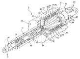
図1は本発明の一つの実施形態に係る減衰装置の断面図、図2は同じく減衰装置の一部を切り欠いて示した斜視図である。
減衰装置1は、第1のシリンダー10、第2のシリンダー20、及び第3のシリンダー30から構成されるケーシング35と、第1のシリンダー10内に配置されるスリーブ40と、第2のシリンダー20内に配置されるフライホイール50と、第2のシリンダー20内に配置される磁場形成手段60と、第3のシリンダー30内に配置される発電機32と、を概略備える。
FIG. 1 is a cross-sectional view of an attenuation device according to one embodiment of the present invention, and FIG. 2 is a perspective view of the same attenuation device.
The damping device 1 includes a
第1のシリンダー10は、先端(図1中左方)に先端開口部11を有しかつ他端(同右方)に連通開口部12を有した軸方向貫通穴13を備える円筒形部材である。また、第2のシリンダー20は、第1のシリンダー10の連通開口部12に一端の開口部21を連通させた状態で、第1のシリンダー10の他端部に同一軸心状に固定された中空の部材である。第2のシリンダー20の他端には、連通開口部29を有する。第3のシリンダー30は、第2のシリンダー20の連通開口部29に一端の開口部31を連通させた状態で、第2のシリンダー20の他端部に同一軸心状に固定された中空の部材である。第3のシリンダー30の他端部には、蓋部材22を備え、蓋部材22には、本減衰装置1を設置する構造物等に接続するためのユニバーサルジョイント23が取付られている。ケーシング35は例えば鋼材で一体に構成される。
第1のシリンダー10の軸方向貫通穴13内には、先端開口部11側から先端部を突出させた中空のスリーブ40が軸方向へ進退自在に配置される。スリーブ40は、第1のシリンダー10の軸方向貫通穴13内に回転不能かつ軸方向へ進退自在に支持されている。即ち、スリーブ40は、第1のシリンダー10内に配置されたブッシュ14により外周面を支持されることにより、第1のシリンダー10内を軸方向に進退動可能に支持されるとともに、キー15によって回転ができないように支持される。
The
In the axial through
スリーブ40の先端(図中左方)には、本減衰装置1を設置する構造物等に接続するための取付部材41が固着される。また、スリーブ40の他端部(同右方)の内部にはボールナット42が固着され、ボールナット42には、その雌螺子部と螺合するボールねじ43が挿通されている。ボールねじ43とボールナット42は、減衰装置1を設置した構造物等から加わる振動、衝撃によって、第1のシリンダー10とスリーブ40とが相対的に軸方向移動した時に、この直進運動を高い効率でボールねじ43の回転運動に変換する機能を有する。
ボールねじ43の他端部には、ボールねじ43と同軸に回転軸部材44が連結されている。回転軸部材44は、第2のシリンダー20内部に延長して設けられ、第2のシリンダー20の端部フランジ26(第1のシリンダー10との境界部)の内周に配置されたベアリング24によって回転可能に軸支される。
回転軸部材44には、フライホイール50の軸心部が固定されている。これにより、フライホイール50は、ボールねじ43の回転に伴って一体的に第2のシリンダー20内で回転する。フライホイール50は、鋼鉄などの強磁性体で構成されており、両端に端部小径部51、52を形成した円柱形状部材である。減衰装置1では、フライホイール50の慣性モーメントによりユニバーサルジョイント23と取付部材41との間に負荷される振動の減衰を行う。なお、図1中符号27は、フライホイール50の組み付け用のナットを示している。
An
A
The shaft portion of the
また、第2のシリンダー20の内壁とフライホイール50の外周との隙間には、密閉領域46が形成される。密閉領域46は、フライホイール50の端部小径部51、52と第2のシリンダー20との間にシール部材47、48を配置して形成される。即ち、一方のシール部材47は、第2のシリンダー20内部に設けた内フランジ部28の内周とフライホイール50の端部小径部51との間に配置され、他のシール部材48は蓋部材22とフライホイール50の他の端部小径部52との間に配置される。また、密閉領域46を形成する第2のシリンダー20の内周壁と、フライホイール50の外周壁とは可能な限り近接するよう構成される。このため、密閉領域46の容積は小さいものとなる。なお、シール部材48及び端部小径部52により、第2のシリンダー20は、端部(図中右側)において閉塞された状態となっている。
A sealed
密閉領域46には、磁気粘性流体49が満たされる。磁気粘性流体(MR流体)は、ベースオイル中に磁性体粒子を混入したものであり、磁場を受けると磁性体粒子が鎖状につながり、せん断変形を受けたり流れを生じた場合に、抵抗力を発生させるものである。この抵抗力の大きさは与える磁場の大きさにより変化し、ある程度までは強い磁場をかければかけるほど上昇する。減衰装置1では、密閉領域46の容積は小さいものであるから、封入される磁気粘性流体49はシリンダー内に磁気粘性流体を封入する従来タイプのものに比べて少量でよい。
また、第2のシリンダー20の内壁には、磁場形成手段60が配置される。磁場形成手段60は、第2のシリンダー20及びフライホイール50を磁気回路の一部として密閉領域46を横切る磁場Mを形成する電磁石である。減衰装置1では、この磁場Mにより密閉領域46内の磁気粘性流体49がフライホイール50に磁気粘性流体49のせん断による抵抗を付与するようにしている。
The sealed
A magnetic
回転軸部材44の他端部には、回転軸部材44と同軸に発電機回転軸33(回転体)が連結されている。発電機回転軸33と回転軸部材44とは、ジョイントにより相対回転不能に連結されている。
発電機32は、発電機回転軸33と一体に回転する複数の永久磁石を有する回転子(界磁)と、回転子の外周に非接触に設けられた複数のコイルを有し、回転子に対して同心状に配置された固定子(電機子)とを備える。
発電機32は、発電機回転軸33と一体に回転し、回転子に設けられた複数の永久磁石が回転することで、回転磁場を形成し、回転子の外周に非接触に設けられた複数のコイルを通過する磁束が回転子の回転に応じて変化するので、交流電力が発生する。
図示する発電機32は直流発電機(DCモータ)であり、発電した交流電力をダイオードブリッジによって全波整流し、コンデンサを用いて平滑化を行った直流電力を出力する。この直流電力は、磁場形成手段60に供給される。即ち、後述する磁場形成手段60のコイル61(図3参照)の一端に発電機32のプラス端子が接続され、他端に発電機32のグランド端子が接続される。
なお発電機32は、電機子を回転子とし、界磁を固定子としたものでもよい。
A generator rotating shaft 33 (rotating body) is connected to the other end of the
The
The
The
The
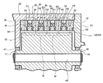
次に磁場形成手段60について説明する。図3は実施形態に係る減衰装置の要部を拡大して示す断面図である。磁場形成手段60は、第2のシリンダー20の内周に配置された複数、例えば4つ並設されたコイル61と、各コイル61の両端に夫々配置され、磁力線を誘導するフェライト材等のヨーク部材62と、コイル61の内径側、かつヨーク部材62の間に配置され、磁力線が通過できない例えばステンレススチール製の非磁性部材63と、ヨーク部材62と非磁性部材63との間で磁気粘性流体をシールするシール部材64とを備えている。
磁場形成手段60において、各コイル61は、各コイル61への通電時に隣接する磁場Mの向きが互いに一致するよう構成されるとともに、第2のシリンダー20及び磁場形成手段60を磁気回路の一部として磁力線が通過する。このため、磁場形成手段60で密閉領域46を横切る磁場Mを形成するに際して構成部材の点数を減じることができる。また磁力線は、密閉領域46以外は強磁性体から成る部材内を通るように構成されるので、密閉領域46を横切る磁場Mを高い効率で形成することができ、少ない電力消費量で強力な磁場を形成することができる。更に、この例では、第2のシリンダー20の内周面、即ち磁場形成手段60とフライホイール50の外周面とを接近して配置しているので、磁場Mをより効率的に密閉領域46内に形成できる。また、磁気粘性流体49による抵抗は、磁気粘性流体49の層の厚さが小さいほど大きくなるので、フライホイール50により大きな抵抗を与えることができる。
Next, the magnetic field forming means 60 will be described. FIG. 3 is an enlarged cross-sectional view illustrating a main part of the attenuation device according to the embodiment. The magnetic
In the magnetic field forming means 60, each
この減衰装置1において、両端の取付部材41とユニバーサルジョイント23とに振動が加わると、この振動の直線運動成分(ボールねじ43の軸方向に沿った運動成分)は、ボールナット42とボールねじ43で効率良く回転運動に変換されてフライホイール50及び発電機回転軸33を回転させる。この回転運動により発電機32が発電した直流電力は、磁場形成手段60のコイル61に供給される。即ち、磁場形成手段60に必要な電力の全てを発電機32が発電した電力によって賄う。磁場形成手段60のコイル61に電流が流れると、密閉領域46内の磁気粘性流体49を磁場Mが横切って磁気粘性流体49の磁性体粒子が磁場形成手段60とフライホイール50との間でつながり、フライホイール50の回転で磁性体粒子の鎖がせん断され、フライホイール50に抵抗を与える。
従って、減衰装置1に加えられる振動は、フライホイール50の慣性モーメントと、フライホイール50の回転に対する磁気粘性流体の抵抗により効果的に減衰される。フライホイール50の磁気粘性流体による抵抗は、磁場形成手段60のコイル61に印加される電流の変化に応じて変化する。本実施形態では、減衰装置1に加えられる振動が大きいほど発電機32が発電する電力が大きくなり、コイル61に印加される電流が大きくなるので、振動の大きさに応じた減衰力を得ることができる。
In the damping device 1, when vibration is applied to the
Therefore, the vibration applied to the damping device 1 is effectively damped by the moment of inertia of the
このように発電機32を、磁場形成手段60を構成する電磁石の電源に利用することで、外部電源を必要とせずに磁場を発生させ、磁気粘性流体49に粘性を付与することができる。従って、減衰装置1の加振中は、磁気粘性流体49による振動の減衰を早める効果を維持することができる。このように、シンプルな構成で効率よく振動を減衰させることができる。
なお、発電機32が発電する電力量の増大に伴うコイル61の焼損を防止するために、発電機32とコイル61との間に過電流保護装置としての定電流回路を配置してもよい。
また、磁場形成手段60のコイル61に供給する電流の大きさは、発電機32の発電容量(発電能力)によっても変えることができる。従って、発電機32の発電容量に基づいて、磁気粘性流体49に作用する磁場の強さを変化させ、フライホイール50が受けるせん断流れの抵抗力を任意に設定して減衰力を調整することができる。
さらに、大きな減衰力を得るためにコイル61の数を増やした場合も、それに応じた発電容量の発電機32を選定する必要がある。磁場の形成に必要な電力と発電機32の発電容量との関係については、使用条件によって異なるので、実験などにより求める。
Thus, by using the
Note that a constant current circuit as an overcurrent protection device may be disposed between the
In addition, the magnitude of the current supplied to the
Furthermore, even when the number of
なお、減衰装置1において、密閉領域46における第2のシリンダー20の内壁に配置した磁場形成手段60とフライホイール50の外周面との間の寸法は、減衰装置1の使用時における定常振動に起因するフライホイール50の回転によって、封入された磁気粘性流体49を沈殿が生じない程度に攪拌するのに十分な程度に小さい寸法であることが望ましい。例えば減衰装置1を建築物などの構造物に使用するときには、建築物に常時加わる車両の通行振動で減衰装置1のフライホイール50が微小回転する。フライホイール50の微小回転で密閉領域46内の磁気粘性流体49が攪拌され、沈殿していた磁性体粒子がベースオイルに混ざり、磁気粘性流体49の性能を発揮できるようになる。フライホイール50と磁場形成手段60との間隔寸法は、実際に使用する建物などの条件により異なるので、実験などにより定める。
In the damping device 1, the dimension between the magnetic field forming means 60 disposed on the inner wall of the
次に本発明の実施の形態に係る他の減衰装置について説明する。図4は第2の実施形態に係る減衰装置の断面図である。第1の実施形態と同一部位には同一符号を付して説明する。
本実施形態に係る減衰装置71は、第1の実施形態に係る減衰装置1におけるボールナット42とボールねじ43の位置を逆にしたものである。そして、ボールナット42、ボールねじ43の位置の変化に伴う取付部材の形状等を第1の実施形態例と変更している他は第1の実施形態例と同じ構造を備える。
即ち、減衰装置71は、第1のシリンダー10と第2のシリンダー20と第3のシリンダー30とからなるケーシング35を備え、第1のシリンダー10内にスリーブ40を軸方向へ進退自在に配置している。また、スリーブ40の第2のシリンダー20側にはボールねじ43の一端部をスリーブ40と同軸に固定し、ボールねじ43の雄螺子部をボールナット42の雌螺子部内に螺合し、更にボールナット42を第2のシリンダー20内に配置されたフライホイール50の中心部に同軸状に固定している。また、第3のシリンダー30内に発電機32を配置し、発電機回転軸33をフライホイール50の中心部に同軸状に連結している。
Next, another attenuation device according to the embodiment of the present invention will be described. FIG. 4 is a cross-sectional view of an attenuation device according to the second embodiment. The same parts as those in the first embodiment will be described with the same reference numerals.
The damping
That is, the damping
フライホイール50の軸方向両端外周と第2のシリンダー20との間に夫々ベアリング72、73、及びシール部材74、75を配置して、フライホイール50を第2のシリンダー20によって回転自在に保持するとともに、第2のシリンダー20内壁とフライホイール50外周との間に密閉領域46を形成している。なお、第2のシリンダー20の他端部は蓋部材22で閉塞されている。
第2のシリンダー20の内周には、磁場形成手段60を配置するとともに、密閉領域46内には磁気粘性流体49を封入している。磁場形成手段60の各コイルには、発電機32が発電した電力を供給する。
第2の実施形態に係る減衰装置71は、ボールナット42とボールねじ43の位置を交換しただけであるので、第1の実施形態に係る減衰装置1と同じ作用及び効果を有する。
A magnetic
The damping
次に第3の実施の形態に係る減衰装置について説明する。図5は第3の実施形態に係る減衰装置の断面図である。減衰装置81は、発電機32と磁場形成手段60との間に制御手段82を備えた他は、第1の実施形態例に係るものと同じ構成を備える。
制御手段82は、発電機32が発電する電力量に基づいて、減衰装置81の磁場形成手段60に印加する電流を調整して減衰状態を制御する。例えば、発電機32による発電量が所定のしきい値以上の場合には、発電量に応じた電力を磁場形成手段60に供給し、発電量が所定のしきい値未満の場合には磁場形成手段60に電力を供給しない構成とすることができる。
このように制御手段82が、磁場形成手段60のコイルに印加する電流を変更することによってフライホイール50の磁気粘性流体による抵抗を調整できるので、減衰装置81の減衰特性を所望のものに設定できる。
Next, an attenuation device according to a third embodiment will be described. FIG. 5 is a cross-sectional view of an attenuation device according to the third embodiment. The
The control means 82 controls the attenuation state by adjusting the current applied to the magnetic field forming means 60 of the
In this way, the control means 82 can adjust the resistance of the
次に第4の実施形態に係る減衰装置について説明する。図6は第4の実施形態に係る減衰装置の断面図である。図7は、制御手段の回路構成の一例を示す図である。減衰装置91は、発電機32が発電した電力を一時的に蓄電する蓄電池92を備えた他は、上述した第3の実施形態例と同じ構造を備える。
制御手段82は、図7に示すように、発電機32が発電する電圧値に応じてON/OFFするコンパレータと、コンパレータがONしたときにONし、コンパレータがOFFしたときにOFFする第1スイッチ素子84及び第2スイッチ素子85と、を備える。なお、符号86、87は、逆流防止用のダイオードである。第1スイッチ素子84は、発電機32からの電力をコイル61に供給するか否かを決定するスイッチであり、第2スイッチ素子85は、蓄電池92からの電力をコイル61に供給するか否かを決定するスイッチである。
制御手段82は、発電機32が発電した電力が所定のしきい値未満の場合にはコンパレータ83がOFFしているので、第1スイッチ素子84及び第2スイッチ素子85がOFF状態となり、発電機32が発電した全ての電力がダイオード87を介して蓄電池92に供給される。また、発電機32が発電した電力が所定のしきい値以上の場合にはコンパレータ83がONするので、第1スイッチ素子84がONし、発電機32が発電した電力を磁場形成手段60のコイル61へ供給する。さらにコンパレータ83のONにより第2スイッチ素子85がONし、蓄電池92の電力を磁場形成手段60のコイル61へ供給する。
例えば減衰装置91を建築物などの構造物に使用した場合、建築物に常時加わる車両の通行振動でフライホイール50が微小回転する。このような場合には、必ずしも磁場形成手段60に電流を印加して制震する必要はないから、発電機32が発電した全ての電力を蓄電池92に供給しても構わない。
他方、建築物に大きな振動が加わった場合には、迅速に振動を減衰させる必要がある。このような場合、フライホイール50の回転により発電機32が発電した電力のみでは、制震に十分な電流を磁場形成手段60に印加することができない虞がある。このような場合には、蓄電池92を放電させることで、発電機32の発電容量を超えた電力を磁場形成手段60に印加することができ、迅速に振動を減衰させることができる。
Next, an attenuation device according to a fourth embodiment will be described. FIG. 6 is a cross-sectional view of an attenuation device according to the fourth embodiment. FIG. 7 is a diagram illustrating an example of a circuit configuration of the control unit. The
As shown in FIG. 7, the control means 82 includes a comparator that is turned ON / OFF according to the voltage value generated by the
Since the
For example, when the damping
On the other hand, when a large vibration is applied to the building, it is necessary to quickly attenuate the vibration. In such a case, there is a possibility that a current sufficient for vibration control cannot be applied to the magnetic field forming means 60 only with the electric power generated by the
次に第5の実施形態に係る減衰装置について説明する。図8は第5の実施形態に係る減衰装置の断面図である。減衰装置101は、磁場形成手段102を永久磁石103とコイル104とから構成したものであり、他の構造は、上述した第1の実施形態例と同じである。減衰装置101において、磁場形成手段102を構成する永久磁石103はリング状であり、コイル104の内側に配置される。永久磁石103は、常時密閉領域46を横切る磁場を常時形成する。このため磁気粘性流体の磁性体粒子が鎖状となり、その沈殿を防止できる。また、減衰装置101では、コイル104に流す電流を調整することにより磁場形成手段102全体での磁場Mの強さを調整し、フライホイール50に加わる粘性抵抗を調整することができる。このため、制振対象に最適な制振特性を得ることができる。
図8は、永久磁石103とコイル104とを、フライホイール50の回転軸の方向に並べた例であるが、永久磁石103とコイル104とをフライホイール50の径方向に並べて配置することで、永久磁石103の磁束をコイル104が発生させる磁束が強めるように、又は弱めるように(相殺するように)配置しても良い。
Next, an attenuation device according to a fifth embodiment will be described. FIG. 8 is a cross-sectional view of an attenuation device according to the fifth embodiment. In the
FIG. 8 is an example in which the
次に本発明に係る減衰装置を使用した構造物の制振装置の実施形態例について説明する。図9は発明の実施形態に係る構造物の制振装置を示す模式図である。この例は、建築物140に前述した第1、第2又は第5の実施形態例に係る減衰装置を設置し、制御手段121で制御するようにしたものである。なお、制御手段121は、複数の減衰装置を制御する点以外は、第3及び第4の実施形態に示した制御手段と同等の手段である。
この実施形態に係る構造物の制振装置は、地盤141、構造部材142、143に減衰装置111、112、113の一端を接続し、減衰装置111、112、113の他端を連結部材145、146、147、148、149、150に接続している。また、地盤141、構造部材142、143、144に加速度計131、132、133、134を配置し、加速度計131、132、133、134の検出値に基づいて制御手段121が減衰装置111、112、113の磁場形成手段に印加する電流を調整して減衰状態を制御する。
更に、制御手段121には、第4の実施形態に示した蓄電池を接続した構成としてもよい。また、制御手段121には商用電源を接続し、商用電源が正常なときには商用電源から制御手段121に電力を供給し、商用電源が停止したときには減衰装置111、112、113の発電機が発電した電力及び蓄電池が放電する電力を制御手段121に供給するようにしてもよい。
Next, an embodiment of the structure damping device using the damping device according to the present invention will be described. FIG. 9 is a schematic diagram showing a structure damping device according to an embodiment of the invention. In this example, the damping device according to the first, second, or fifth embodiment described above is installed in the
In the structure damping device according to this embodiment, one end of the damping
Furthermore, the control means 121 may be configured to be connected to the storage battery shown in the fourth embodiment. Also, a commercial power source is connected to the control means 121. When the commercial power supply is normal, power is supplied from the commercial power source to the control means 121. When the commercial power supply is stopped, the generators of the
この例では、加速度計131、132、133、134で検出した地盤141及び構造部材142、143、144の応答状態に基づいて、減衰装置111、112、113の減衰力を変更し、建物全体としての制振を図ることができる。
なお、減衰装置や加速度計をどのように建築物に配置するかは、適宜変更することができる。図10乃至図12は構造物の制振装置における減衰装置の取付例を示す模式図である。なお、各例では、各減衰値装置は、前記例と同様に、建築物に配置した加速度計の検出値に基づいて制御手段で制御される。
In this example, the damping force of the damping
Note that how the attenuation device and the accelerometer are arranged in the building can be changed as appropriate. FIG. 10 to FIG. 12 are schematic views showing an example of attachment of an attenuation device in a structure damping device. In each example, each attenuation value device is controlled by the control means based on the detection value of the accelerometer arranged in the building, as in the above example.
図10に示す例では、減衰装置161、162、163を建築物170の各フロアを構成する地盤171、構造部材172、173、174に対して筋交い状に配置している。
また、図11に示す例では、減衰装置181、182、183により、建築物184の各フロアの構造部材185、186、187と、建築物188の各フロアの構造部材189、190、191をそれぞれ連結している。
更に、図12に示す例は、建物200の免震構造に減衰装置201を使用したものである。この例では、構造物の制振装置として建物200と地盤204との間に積層ゴムアイソレータ202、203を配置し、地盤204と建物200の最下層を構成する構造部材205との間に減衰装置201を配置している。
In the example illustrated in FIG. 10, the
Further, in the example shown in FIG. 11, the
Furthermore, the example shown in FIG. 12 uses the damping
上記各例では、制御手段121は、建築物に配置した加速度計に基づいて減衰装置を制御しているが、制御手段121は、外部の地震情報に基づいて前記減衰装置を制御することができる。これにより、あらかじめ得られる外部の地震情報に基づいて減衰装置の動作を開始し、構造物を地震波到来の以前から振動を減衰させる状態とでき、初期振動に対して効果的な減衰効果を得ることができる。
また、本発明では、実施形態例の制御手段が、定期的に磁場形成手段を駆動して減衰装置の密閉領域に磁場を形成させることができる。これにより、磁場形成手段を駆動させ磁気粘性流体の磁性体粒子を鎖状としてその沈殿を防止することができ、突発的に加えられる地震振動に対して制振装置がその制振性能を発揮できる。
In each of the above examples, the
In the present invention, the control means of the embodiment can drive the magnetic field forming means periodically to form a magnetic field in the sealed region of the attenuation device. As a result, the magnetic field forming means can be driven and the magnetic particles of the magnetorheological fluid can be chained to prevent the precipitation, and the damping device can exhibit its damping performance against suddenly applied earthquake vibration. .
1…減衰装置、10…シリンダー、11…先端開口部、12…連通開口部、13…軸方向貫通穴、14…ブッシュ、15…キー、20…シリンダー、21…開口部、22…蓋部材、23…ユニバーサルジョイント、24…ベアリング、26…端部フランジ、27…ナット、28…内フランジ部、29…連通開口部、30…シリンダー、31…開口部、32…発電機、33…発電機回転軸、35…ケーシング、40…スリーブ、41…取付部材、42…ボールナット、44…回転軸部材、46…密閉領域、47、48…シール部材、49…磁気粘性流体、50…フライホイール、51、52…端部小径部、60…磁場形成手段、61…コイル、62…ヨーク部材、63…非磁性部材、64…シール部材、71…減衰装置、72…ベアリング、74…シール部材、81…減衰装置、82…制御手段、83…コンパレータ、84…第1スイッチ素子、85…第2スイッチ素子、86、87…ダイオード、91…減衰装置、92…蓄電池、101…減衰装置、102…磁場形成手段、103…永久磁石、104…コイル、111、112、113…減衰装置、121…制御手段、131、132、133、134…加速度計、140…建築物、141…地盤、142、143、144…構造部材、145…連結部材、161、162、163…減衰装置、170…建築物、171…地盤、172、173、174…構造部材、181、182、183…減衰装置、184…建築物、185、186、187…構造部材、188…建築物、189、190、191…構造部材、200…建物、201…減衰装置、202、203…積層ゴムアイソレータ、204…地盤、205…構造部材、210…減衰装置、211…磁気粘性流体、212…シリンダー、212a…取付部、213…ピストンロッド、213a…取付部、214…ピストン、215…バイパス管、216…磁界形成手段
DESCRIPTION OF SYMBOLS 1 ... Damping device, 10 ... Cylinder, 11 ... Tip opening part, 12 ... Communication opening part, 13 ... Axial through-hole, 14 ... Bush, 15 ... Key, 20 ... Cylinder, 21 ... Opening part, 22 ... Cover member, 23 ... Universal joint, 24 ... Bearing, 26 ... End flange, 27 ... Nut, 28 ... Inner flange, 29 ... Communication opening, 30 ... Cylinder, 31 ... Opening, 32 ... Generator, 33 ... Generator rotation Shaft, 35 ... casing, 40 ... sleeve, 41 ... mounting member, 42 ... ball nut, 44 ... rotating shaft member, 46 ... sealed region, 47, 48 ... seal member, 49 ... magnetorheological fluid, 50 ... flywheel, 51 , 52 ... small diameter part at the end, 60 ... magnetic field forming means, 61 ... coil, 62 ... yoke member, 63 ... nonmagnetic member, 64 ... seal member, 71 ... damping device, 72 ... bearing, 7 DESCRIPTION OF SYMBOLS ... Sealing member, 81 ... Attenuator, 82 ... Control means, 83 ... Comparator, 84 ... First switch element, 85 ... Second switch element, 86, 87 ... Diode, 91 ... Attenuator, 92 ... Storage battery, 101 ... Attenuation DESCRIPTION OF
Claims (13)
前記第1のシリンダーの前記先端開口部内に嵌合して前記軸方向貫通穴に回転不能かつ軸方向へ進退自在に支持された中空のスリーブと、
前記スリーブ内に固定されたボールナットと、
該ボールナットの雌螺子部と螺合するボールねじと、
強磁性体材料で形成され、前記第2のシリンダーの中空内部に回転自在に配置されるとともに、前記ボールねじと同軸に固定されて回転駆動されるフライホイールと、
前記第2のシリンダー内壁と前記フライホイール外周との隙間に密閉領域を形成するシール部材と、
前記第2のシリンダー内壁に配置され、前記フライホイールを磁気回路の一部として前記密閉領域を横切る磁場を形成する電磁石を備えた磁場形成手段と、
前記密閉領域内に封入される磁気粘性流体と、
前記フライホイールと一体回転する界磁又は電機子からなる回転子、及び該回転子と同心状に配置された電機子又は界磁からなる固定子を有する発電機と、
前記発電機が発電した電力を蓄電する蓄電池と、を備え、
前記発電機の発電量が所定のしきい値未満の場合には前記発電機が発電した電力を前記蓄電池に蓄電し、前記発電機の発電量が所定のしきい値以上の場合には前記発電機が発電した電力を前記電磁石に供給することを特徴とする減衰装置。 A first cylinder having an axial through-hole having a tip opening at the tip and a communication opening at the other end, and the first cylinder in a state where the one opening is in communication with the communication opening. A casing having a hollow second cylinder fixed in the same axial center to the other end of the cylinder and closed at the other end;
A hollow sleeve that fits within the tip opening of the first cylinder and is supported in the axial through hole so as not to rotate and to advance and retract in the axial direction;
A ball nut fixed in the sleeve;
A ball screw threadably engaged with the female screw portion of the ball nut;
A flywheel formed of a ferromagnetic material, rotatably disposed inside the hollow of the second cylinder, and fixedly driven coaxially with the ball screw;
A seal member that forms a sealed region in a gap between the inner wall of the second cylinder and the outer periphery of the flywheel;
Magnetic field forming means provided with an electromagnet disposed on the inner wall of the second cylinder and forming a magnetic field across the sealed region with the flywheel as part of a magnetic circuit;
A magnetorheological fluid enclosed in the sealed region ;
A generator having a front Symbol flywheel integrally rotating field磁又the rotor consisting of an armature, and said rotor and concentrically arranged armature or stator consisting of field,
A storage battery for storing electric power generated by the generator ,
When the power generation amount of the generator is less than a predetermined threshold value, the electric power generated by the generator is stored in the storage battery, and when the power generation amount of the generator is not less than a predetermined threshold value, the power generation damping device and supplying the power machine is power to the electromagnet.
前記第1のシリンダーの前記先端開口部内に嵌合して前記軸方向貫通穴に回転不能かつ軸方向へ進退自在に支持された中空のスリーブと、
前記スリーブ内に固定されたボールねじと、
該ボールねじの雄螺子部と螺合するボールナットと、
強磁性体材料で形成され、前記第2のシリンダーの中空内部に回転自在に配置されるとともに、前記ボールナットと同軸に固定されて回転駆動されるフライホイールと、
前記第2のシリンダー内壁と前記フライホイール外周との隙間に密閉領域を形成するシール部材と、
前記第2のシリンダー内壁に配置され、前記フライホイールを磁気回路の一部として前記密閉領域を横切る磁場を形成する電磁石を備えた磁場形成手段と、
前記密閉領域内に封入される磁気粘性流体と、
前記フライホイールと一体回転する界磁又は電機子からなる回転子、及び該回転子と同心状に配置された電機子又は界磁からなる固定子を有する発電機と、
前記発電機が発電した電力を蓄電する蓄電池と、を備え、
前記発電機の発電量が所定のしきい値未満の場合には前記発電機が発電した電力を前記蓄電池に蓄電し、前記発電機の発電量が所定のしきい値以上の場合には前記発電機が発電した電力を前記電磁石に供給することを特徴とする減衰装置。 A first cylinder having an axial through-hole having a tip opening at the tip and a communication opening at the other end, and the first cylinder in a state where the one opening is in communication with the communication opening. A casing having a hollow second cylinder fixed in the same axial center to the other end of the cylinder and closed at the other end;
A hollow sleeve that fits within the tip opening of the first cylinder and is supported in the axial through hole so as not to rotate and to advance and retract in the axial direction;
A ball screw fixed in the sleeve;
A ball nut threadably engaged with the male screw portion of the ball screw;
A flywheel formed of a ferromagnetic material, rotatably disposed inside the hollow of the second cylinder, and fixedly driven coaxially with the ball nut;
A seal member that forms a sealed region in a gap between the inner wall of the second cylinder and the outer periphery of the flywheel;
Magnetic field forming means provided with an electromagnet disposed on the inner wall of the second cylinder and forming a magnetic field across the sealed region with the flywheel as part of a magnetic circuit;
A magnetorheological fluid enclosed in the sealed region ;
A generator having a front Symbol flywheel integrally rotating field磁又the rotor consisting of an armature, and said rotor and concentrically arranged armature or stator consisting of field,
A storage battery for storing electric power generated by the generator ,
When the power generation amount of the generator is less than a predetermined threshold value, the electric power generated by the generator is stored in the storage battery, and when the power generation amount of the generator is not less than a predetermined threshold value, the power generation damping device and supplying the power machine is power to the electromagnet.
前記制御手段が、前記加速度計の検出値に基づいて前記磁場形成手段を制御することを特徴とする請求項9に記載の構造物の制振装置。 Comprising an accelerometer for detecting the state of vibration of the structure;
The structure control device according to claim 9, wherein the control unit controls the magnetic field forming unit based on a detection value of the accelerometer.
前記制御手段が、前記各減衰装置の磁場形成手段を対応する加速度計の検出値に基づいて制御することを特徴とする請求項10に記載の構造物の制振装置。 The accelerometer is arranged corresponding to the damping device;
11. The structure damping device according to claim 10, wherein the control unit controls the magnetic field forming unit of each attenuation device based on a detection value of a corresponding accelerometer.
Priority Applications (3)
| Application Number | Priority Date | Filing Date | Title |
|---|---|---|---|
| JP2012285165A JP5925672B2 (en) | 2012-12-27 | 2012-12-27 | Damping device and structure damping device |
| PCT/JP2013/085144 WO2014104313A1 (en) | 2012-12-27 | 2013-12-27 | Damping device and damping apparatus for structure |
| US14/758,499 US9416533B2 (en) | 2012-12-27 | 2013-12-27 | Damping device and vibration control apparatus for structure |
Applications Claiming Priority (1)
| Application Number | Priority Date | Filing Date | Title |
|---|---|---|---|
| JP2012285165A JP5925672B2 (en) | 2012-12-27 | 2012-12-27 | Damping device and structure damping device |
Publications (3)
| Publication Number | Publication Date |
|---|---|
| JP2014126177A JP2014126177A (en) | 2014-07-07 |
| JP2014126177A5 JP2014126177A5 (en) | 2015-12-24 |
| JP5925672B2 true JP5925672B2 (en) | 2016-05-25 |
Family
ID=51021382
Family Applications (1)
| Application Number | Title | Priority Date | Filing Date |
|---|---|---|---|
| JP2012285165A Active JP5925672B2 (en) | 2012-12-27 | 2012-12-27 | Damping device and structure damping device |
Country Status (3)
| Country | Link |
|---|---|
| US (1) | US9416533B2 (en) |
| JP (1) | JP5925672B2 (en) |
| WO (1) | WO2014104313A1 (en) |
Families Citing this family (42)
| Publication number | Priority date | Publication date | Assignee | Title |
|---|---|---|---|---|
| US9509204B2 (en) | 2013-12-12 | 2016-11-29 | The Boeing Company | Motion-damping systems between base structure and an attached component and methods including the same |
| US9670981B2 (en) * | 2013-12-12 | 2017-06-06 | The Boeing Company | Motion-damping systems and methods including the same |
| EP3196505B1 (en) * | 2014-09-15 | 2019-07-24 | Zhengqing Chen | Outer cup rotary axial eddy current damper |
| JP6463091B2 (en) * | 2014-11-19 | 2019-01-30 | 国立大学法人神戸大学 | Variable mass inertial damping device |
| CN104626912A (en) * | 2015-02-02 | 2015-05-20 | 江苏大学 | Hydro-electric integrated type car suspension impedance control device |
| DE102015104927A1 (en) * | 2015-03-31 | 2016-10-06 | Inventus Engineering Gmbh | Damper for damping a relative movement |
| KR102027267B1 (en) * | 2015-10-07 | 2019-10-01 | 티엠티 머시너리 가부시키가이샤 | Liquid damper system |
| JP6580457B2 (en) * | 2015-10-29 | 2019-09-25 | Thk株式会社 | Rotating inertia mass damper |
| EP3400109A4 (en) * | 2016-01-05 | 2019-10-16 | Milwaukee Electric Tool Corporation | Vibration reduction system and method for power tools |
| JP6605702B2 (en) * | 2016-02-18 | 2019-11-13 | アルプスアルパイン株式会社 | Operating device |
| WO2017164074A1 (en) * | 2016-03-23 | 2017-09-28 | 株式会社Lixil | Damper device and fitting |
| JP6804206B2 (en) * | 2016-03-23 | 2020-12-23 | 株式会社Lixil | Damper equipment and fittings |
| JP6668157B2 (en) * | 2016-04-22 | 2020-03-18 | 株式会社免制震ディバイス | Vibration suppression device for structures |
| US10088006B2 (en) * | 2016-05-19 | 2018-10-02 | The Boeing Company | Rotational inerter and method for damping an actuator |
| CN105971357B (en) * | 2016-06-02 | 2018-05-01 | 燕山大学 | Piston type SMA- Piezoelectric anisotropy friction-changing dampers |
| EP3501087B1 (en) * | 2016-08-17 | 2022-11-23 | Project Phoenix LLC | Motor operated accumulator |
| JP6670213B2 (en) * | 2016-09-30 | 2020-03-18 | 株式会社Lixil | Door body moving speed adjustment device and fittings |
| TWI716651B (en) * | 2016-11-25 | 2021-01-21 | 日商日立汽車系統股份有限公司 | Damping device |
| DE102016124115B4 (en) * | 2016-12-12 | 2022-06-09 | Inventus Engineering Gmbh | rotary damper |
| CN106849480B (en) * | 2017-02-13 | 2019-03-05 | 沈阳鼓风机集团核电泵业有限公司 | A kind of nuclear power main pump flywheel of back taper structure |
| CN106836546B (en) * | 2017-03-31 | 2019-03-19 | 西京学院 | A kind of half active friction energy consumer of magnetic control |
| US10619699B2 (en) * | 2017-04-21 | 2020-04-14 | United States Of America As Represented By The Administrator Of Nasa | Self-turning compact vibration damper |
| DE102017111032A1 (en) * | 2017-05-20 | 2018-11-22 | Inventus Engineering Gmbh | Device with a controllable rotary damper |
| US11204070B2 (en) * | 2017-06-01 | 2021-12-21 | Hendrickson Usa, L.L.C. | Brake component positioning assembly |
| CN107202089A (en) * | 2017-07-10 | 2017-09-26 | 江苏大学 | A kind of self-powered magneto-rheological vibration damper |
| JP7101556B2 (en) * | 2018-07-27 | 2022-07-15 | 日本製鉄株式会社 | Eddy current damper |
| EP3599164B1 (en) * | 2018-07-27 | 2020-11-25 | LEONARDO S.p.A. | Helicopter kit |
| JP2020045929A (en) * | 2018-09-14 | 2020-03-26 | 三菱重工業株式会社 | Vibration damping device and electric actuator |
| CN109139765B (en) * | 2018-10-25 | 2023-06-23 | 华北水利水电大学 | Ternary vibration damper with parallel damping and spring units, design and assembly method |
| CN109630597B (en) * | 2018-12-26 | 2020-11-27 | 合肥工业大学 | Magneto-rheological inerter device and continuous adjusting method of inerter coefficient thereof |
| CN112696451B (en) | 2020-01-09 | 2022-09-06 | 北京京西重工有限公司 | Rotary damper assembly |
| CN112093616B (en) * | 2020-09-08 | 2022-04-12 | 浙江师范大学行知学院 | Cable driving brake system based on magneto-rheological and control method thereof |
| CN112128285B (en) * | 2020-09-14 | 2021-09-24 | 湖南大学 | Vertical tuned mass magnetic screw type inertial capacitance eddy current damper |
| CN112196108A (en) * | 2020-10-29 | 2021-01-08 | 东北电力大学 | Energy dissipation damper for wind-proof inhaul cable of air film building |
| JP2022133520A (en) * | 2021-03-02 | 2022-09-14 | 本田技研工業株式会社 | suspension device |
| CN113152724B (en) * | 2021-05-08 | 2022-03-11 | 广东宇泰制震装备股份有限公司 | Shock insulation support for building with fire prevention fire behavior |
| US11808327B2 (en) * | 2021-07-28 | 2023-11-07 | Columbus Mckinnon Corporation | Linear actuator with an integrated variable frequency drive |
| CN114151496A (en) * | 2021-09-17 | 2022-03-08 | 西安工业大学 | Electromagnetic magneto-rheological inertia mass damper |
| CN113833148B (en) * | 2021-10-13 | 2022-12-23 | 国网福建省电力有限公司厦门供电公司 | Antitorque antidetonation tensile building structure that building engineering used |
| CN114607062B (en) * | 2022-03-24 | 2023-06-06 | 华东交通大学 | Speed type electromagnetic vortex inertia damper with adjustable inertia capacity damping |
| CN115233849A (en) * | 2022-08-11 | 2022-10-25 | 安徽工业大学 | Initiative start-up formula intelligence isolation bearing |
| CN115419309A (en) * | 2022-08-31 | 2022-12-02 | 山东百顿减震科技有限公司 | Building vibration isolation method, equipment and medium based on intelligent vibration isolation support |
Family Cites Families (11)
| Publication number | Priority date | Publication date | Assignee | Title |
|---|---|---|---|---|
| FR2606109B1 (en) * | 1986-10-31 | 1992-12-04 | Atsugi Motor Parts Co Ltd | ROTARY HANDLING DEVICE AND VARIABLE ACTION SHOCK ABSORBER |
| JP3408706B2 (en) | 1996-12-27 | 2003-05-19 | 住友建設株式会社 | Damping bar and damping device using the same |
| JP4416937B2 (en) | 2000-11-30 | 2010-02-17 | 三和テッキ株式会社 | Magnetorheological fluid flow damping device |
| US6448679B1 (en) * | 2000-12-14 | 2002-09-10 | Joseph Imlach | Passive magnetic support and damping system |
| JP2005180492A (en) | 2003-12-16 | 2005-07-07 | Ntt Power & Building Facilities Inc | Design method, design support system, design support program and design method of damping system |
| JP4205002B2 (en) * | 2004-03-10 | 2009-01-07 | トヨタ自動車株式会社 | Electromagnetic shock absorber |
| JP4500786B2 (en) * | 2006-04-27 | 2010-07-14 | カヤバ工業株式会社 | Shock absorber |
| JP5260936B2 (en) * | 2007-10-25 | 2013-08-14 | トヨタ自動車株式会社 | Electromagnetic shock absorber for vehicles |
| JP5601825B2 (en) * | 2009-11-13 | 2014-10-08 | 株式会社免制震ディバイス | Damper and seismic isolation mechanism |
| JP5016086B2 (en) * | 2010-06-07 | 2012-09-05 | Thk株式会社 | Damping device using ball screw |
| JP5750280B2 (en) * | 2011-03-07 | 2015-07-15 | 株式会社構造計画研究所 | Structure damping device |
-
2012
- 2012-12-27 JP JP2012285165A patent/JP5925672B2/en active Active
-
2013
- 2013-12-27 WO PCT/JP2013/085144 patent/WO2014104313A1/en active Application Filing
- 2013-12-27 US US14/758,499 patent/US9416533B2/en active Active
Also Published As
| Publication number | Publication date |
|---|---|
| US20150345134A1 (en) | 2015-12-03 |
| JP2014126177A (en) | 2014-07-07 |
| US9416533B2 (en) | 2016-08-16 |
| WO2014104313A1 (en) | 2014-07-03 |
Similar Documents
| Publication | Publication Date | Title |
|---|---|---|
| JP5925672B2 (en) | Damping device and structure damping device | |
| JP5750280B2 (en) | Structure damping device | |
| JP2014126177A5 (en) | ||
| JP6317822B2 (en) | One degree of freedom magnetic vibration isolator | |
| JP5460566B2 (en) | Axial gap type rotating electrical machine | |
| US8707822B2 (en) | Active electric torsional vibration damper and method to realize the same | |
| JP6843179B2 (en) | Damping assembly for use in devices with aerodynamic moving surfaces | |
| KR100622465B1 (en) | Electromagnetic shock absorber | |
| JP2922886B2 (en) | Damper for deployment mechanism of spacecraft | |
| JP2010276200A (en) | Brake with magnetic field responsive material | |
| CN111033078B (en) | Vortex type vibration damper | |
| JP5585884B2 (en) | Robot and robot system | |
| WO2017061147A1 (en) | Liquid damper system | |
| JP2017110756A (en) | Variable inertia mass type vibration control device | |
| WO2020116344A1 (en) | Eddy-current type damper | |
| CN101832355A (en) | Double-out-rod adaptive double-control magneto-rheological damper | |
| JP2017110758A (en) | Variable inertia mass type vibration control device | |
| US9966829B2 (en) | Reduced-vibration stepper motor | |
| JP7135725B2 (en) | Eddy current damper | |
| JP2011179636A (en) | Electromagnetic shock absorber | |
| US11821471B2 (en) | Programmable magnetorheological fluid clutch apparatus | |
| CN104079111B (en) | A kind of shutter shimmy damping device for space borne imagery load | |
| CN203967892U (en) | For the shutter shimmy damping device of space borne imagery load | |
| JP2004011753A (en) | Electromagnetic shock absorber | |
| KR101382876B1 (en) | Rotary motor using the principle of magnetostriction |
Legal Events
| Date | Code | Title | Description |
|---|---|---|---|
| A521 | Request for written amendment filed |
Free format text: JAPANESE INTERMEDIATE CODE: A523 Effective date: 20151105 |
|
| A621 | Written request for application examination |
Free format text: JAPANESE INTERMEDIATE CODE: A621 Effective date: 20151105 |
|
| A871 | Explanation of circumstances concerning accelerated examination |
Free format text: JAPANESE INTERMEDIATE CODE: A871 Effective date: 20151105 |
|
| A975 | Report on accelerated examination |
Free format text: JAPANESE INTERMEDIATE CODE: A971005 Effective date: 20160107 |
|
| A131 | Notification of reasons for refusal |
Free format text: JAPANESE INTERMEDIATE CODE: A131 Effective date: 20160112 |
|
| A521 | Request for written amendment filed |
Free format text: JAPANESE INTERMEDIATE CODE: A523 Effective date: 20160311 |
|
| TRDD | Decision of grant or rejection written | ||
| A01 | Written decision to grant a patent or to grant a registration (utility model) |
Free format text: JAPANESE INTERMEDIATE CODE: A01 Effective date: 20160405 |
|
| A61 | First payment of annual fees (during grant procedure) |
Free format text: JAPANESE INTERMEDIATE CODE: A61 Effective date: 20160420 |
|
| R150 | Certificate of patent or registration of utility model |
Ref document number: 5925672 Country of ref document: JP Free format text: JAPANESE INTERMEDIATE CODE: R150 |
|
| S531 | Written request for registration of change of domicile |
Free format text: JAPANESE INTERMEDIATE CODE: R313531 |
|
| R350 | Written notification of registration of transfer |
Free format text: JAPANESE INTERMEDIATE CODE: R350 |
|
| R250 | Receipt of annual fees |
Free format text: JAPANESE INTERMEDIATE CODE: R250 |
|
| R250 | Receipt of annual fees |
Free format text: JAPANESE INTERMEDIATE CODE: R250 |
|
| R250 | Receipt of annual fees |
Free format text: JAPANESE INTERMEDIATE CODE: R250 |
|
| R250 | Receipt of annual fees |
Free format text: JAPANESE INTERMEDIATE CODE: R250 |
|
| R250 | Receipt of annual fees |
Free format text: JAPANESE INTERMEDIATE CODE: R250 |