EP3369931A1 - Fluid machine - Google Patents
Fluid machine Download PDFInfo
- Publication number
- EP3369931A1 EP3369931A1 EP17760067.3A EP17760067A EP3369931A1 EP 3369931 A1 EP3369931 A1 EP 3369931A1 EP 17760067 A EP17760067 A EP 17760067A EP 3369931 A1 EP3369931 A1 EP 3369931A1
- Authority
- EP
- European Patent Office
- Prior art keywords
- groove
- crankshaft
- lubricant
- sliding region
- thrust plate
- Prior art date
- Legal status (The legal status is an assumption and is not a legal conclusion. Google has not performed a legal analysis and makes no representation as to the accuracy of the status listed.)
- Granted
Links
Images


Classifications
-
- F—MECHANICAL ENGINEERING; LIGHTING; HEATING; WEAPONS; BLASTING
- F04—POSITIVE - DISPLACEMENT MACHINES FOR LIQUIDS; PUMPS FOR LIQUIDS OR ELASTIC FLUIDS
- F04B—POSITIVE-DISPLACEMENT MACHINES FOR LIQUIDS; PUMPS
- F04B39/00—Component parts, details, or accessories, of pumps or pumping systems specially adapted for elastic fluids, not otherwise provided for in, or of interest apart from, groups F04B25/00 - F04B37/00
- F04B39/02—Lubrication
- F04B39/0223—Lubrication characterised by the compressor type
- F04B39/023—Hermetic compressors
- F04B39/0238—Hermetic compressors with oil distribution channels
- F04B39/0246—Hermetic compressors with oil distribution channels in the rotating shaft
-
- F—MECHANICAL ENGINEERING; LIGHTING; HEATING; WEAPONS; BLASTING
- F04—POSITIVE - DISPLACEMENT MACHINES FOR LIQUIDS; PUMPS FOR LIQUIDS OR ELASTIC FLUIDS
- F04C—ROTARY-PISTON, OR OSCILLATING-PISTON, POSITIVE-DISPLACEMENT MACHINES FOR LIQUIDS; ROTARY-PISTON, OR OSCILLATING-PISTON, POSITIVE-DISPLACEMENT PUMPS
- F04C18/00—Rotary-piston pumps specially adapted for elastic fluids
- F04C18/02—Rotary-piston pumps specially adapted for elastic fluids of arcuate-engagement type, i.e. with circular translatory movement of co-operating members, each member having the same number of teeth or tooth-equivalents
- F04C18/0207—Rotary-piston pumps specially adapted for elastic fluids of arcuate-engagement type, i.e. with circular translatory movement of co-operating members, each member having the same number of teeth or tooth-equivalents both members having co-operating elements in spiral form
- F04C18/0215—Rotary-piston pumps specially adapted for elastic fluids of arcuate-engagement type, i.e. with circular translatory movement of co-operating members, each member having the same number of teeth or tooth-equivalents both members having co-operating elements in spiral form where only one member is moving
-
- F—MECHANICAL ENGINEERING; LIGHTING; HEATING; WEAPONS; BLASTING
- F04—POSITIVE - DISPLACEMENT MACHINES FOR LIQUIDS; PUMPS FOR LIQUIDS OR ELASTIC FLUIDS
- F04C—ROTARY-PISTON, OR OSCILLATING-PISTON, POSITIVE-DISPLACEMENT MACHINES FOR LIQUIDS; ROTARY-PISTON, OR OSCILLATING-PISTON, POSITIVE-DISPLACEMENT PUMPS
- F04C23/00—Combinations of two or more pumps, each being of rotary-piston or oscillating-piston type, specially adapted for elastic fluids; Pumping installations specially adapted for elastic fluids; Multi-stage pumps specially adapted for elastic fluids
- F04C23/008—Hermetic pumps
-
- F—MECHANICAL ENGINEERING; LIGHTING; HEATING; WEAPONS; BLASTING
- F04—POSITIVE - DISPLACEMENT MACHINES FOR LIQUIDS; PUMPS FOR LIQUIDS OR ELASTIC FLUIDS
- F04C—ROTARY-PISTON, OR OSCILLATING-PISTON, POSITIVE-DISPLACEMENT MACHINES FOR LIQUIDS; ROTARY-PISTON, OR OSCILLATING-PISTON, POSITIVE-DISPLACEMENT PUMPS
- F04C29/00—Component parts, details or accessories of pumps or pumping installations, not provided for in groups F04C18/00 - F04C28/00
- F04C29/02—Lubrication; Lubricant separation
- F04C29/028—Means for improving or restricting lubricant flow
-
- F—MECHANICAL ENGINEERING; LIGHTING; HEATING; WEAPONS; BLASTING
- F04—POSITIVE - DISPLACEMENT MACHINES FOR LIQUIDS; PUMPS FOR LIQUIDS OR ELASTIC FLUIDS
- F04B—POSITIVE-DISPLACEMENT MACHINES FOR LIQUIDS; PUMPS
- F04B39/00—Component parts, details, or accessories, of pumps or pumping systems specially adapted for elastic fluids, not otherwise provided for in, or of interest apart from, groups F04B25/00 - F04B37/00
- F04B39/02—Lubrication
- F04B39/0223—Lubrication characterised by the compressor type
- F04B39/023—Hermetic compressors
- F04B39/0261—Hermetic compressors with an auxiliary oil pump
-
- F—MECHANICAL ENGINEERING; LIGHTING; HEATING; WEAPONS; BLASTING
- F04—POSITIVE - DISPLACEMENT MACHINES FOR LIQUIDS; PUMPS FOR LIQUIDS OR ELASTIC FLUIDS
- F04C—ROTARY-PISTON, OR OSCILLATING-PISTON, POSITIVE-DISPLACEMENT MACHINES FOR LIQUIDS; ROTARY-PISTON, OR OSCILLATING-PISTON, POSITIVE-DISPLACEMENT PUMPS
- F04C2240/00—Components
- F04C2240/80—Other components
Definitions
- the present invention relates to a fluid machine.
- a housing internally accommodates a compression mechanism and a motor (electric motor) which drives the compression mechanism.
- the compression mechanism and a motor rotor are combined with each other by the same crankshaft.
- the crankshaft is disposed so that an axial direction is set to be a vertical direction, and a thrust load is applied to a lower end portion of the crankshaft.
- the thrust load means a dead weight of the crankshaft and the motor rotor and an axial force of a magnet pulling force generated during operation.
- PTLS 1 and 2 disclose that a lubricant is supplied to the thrust bearing so as to improve lubricating ability in the thrust bearing. Then, in the lower end portion of the crankshaft and a sliding region of the thrust bearing, an oil supply groove for supplying the lubricant to the thrust bearing is entirely formed in a radial direction, that is, so as to penetrate from an inner peripheral portion to an outer peripheral portion.
- An oil passage inside a compressor is formed at the center of the crankshaft, and is branched to a journal bearing for supporting a radial load or a compression mechanism.
- the lubricant is supplied from a pump installed around the lower end portion of the crankshaft to the oil passage disposed at the center of the crankshaft. Thereafter, the lubricant is supplied to the journal bearing or the compression mechanism via the oil passage.
- the present invention is made in view of these circumstances, and an object thereof is to provide a fluid machine which can reduce friction loss occurring in a lower end portion of a crankshaft and which can reliably supply a lubricant to other sliding portions.
- a fluid machine according to the present invention adopts the following means.
- a fluid machine including an annular plate part that has a through-hole through which a lubricant is circulated, and a crankshaft that is placed on an upper surface of the plate part, and that internally has a circulation passage for circulating the lubricant passing through the through-hole of the plate part.
- a crankshaft In a sliding region between the crankshaft and the plate part, at least one of the crankshaft and the plate part has a recess groove to which the lubricant is supplied from the through-hole.
- An outer end portion of the groove in a radial direction is located inward of an outermost peripheral portion in the sliding region.
- the through-hole is formed in the plate part, the circulation passage is formed inside the crankshaft placed on the upper surface of the plate part. After the lubricant is circulated through the through-hole of the plate part, the lubricant flows in the circulation passage of the crankshaft.
- the groove is formed in at least one of the crankshaft and the plate part, and the lubricant is supplied from the through-hole to the groove.
- the sliding region of the crankshaft and the plate part are filled with the lubricant, and an oil film is formed, thereby enabling friction loss to be reduced.
- the outer end portion of the groove in the radial direction is located inward of the outermost peripheral portion in the above-described sliding region. Accordingly, the lubricant supplied to the groove is less likely to leak from an inner peripheral side to an outer peripheral side in the sliding region.
- the outer end portion of the groove in the radial direction may be located outward of an intermediate position between an innermost peripheral portion and the outermost peripheral portion in the sliding region.
- the groove can supply the lubricant outward of the intermediate position between the innermost peripheral portion and the outermost peripheral portion in the sliding region.
- an area of a region having the groove in the sliding region may be 50% to 80% of a total area located inward of the outer end portion of the groove in the radial direction in the sliding region.
- an inner portion of the groove in the radial direction or a portion facing the inner portion of the groove in the radial direction in the crankshaft or the plate part may have a tapered surface.
- the inner portion of the groove in the radial direction or the portion facing the inner portion has the tapered surface. Accordingly, the inner portion of the groove in the radial direction is widened in a height direction, and the lubricant is likely to be supplied into the groove.
- the groove may have a stepped shape, a tapered shape, or a dimple shape.
- a hermetic scroll compressor 1 as a scroll fluid machine includes a vertically long cylindrical hermetic housing 2 whose bottom portion is hermetic by a lower cover. An upper part of the hermetic housing 2 is hermetic by a discharge cover 3 and an upper cover 4, a discharge chamber 5 for discharging compressed high-pressure gas is formed between the discharge cover 3 and the upper cover 4.
- an upper bearing member (frame member) 6 is fixedly installed in the upper part, a scroll compression mechanism 7 is incorporated via the upper bearing member 6, and an electric motor 10 having a stator 8 and a rotor 9 is installed in the lower part.
- the electric motor 10 is incorporated by the stator 8 fixedly installed in the hermetic housing 2, and a crankshaft 11 is fixed to the rotor 9.
- crankshaft 11 An upper end of the crankshaft 11 has a crank pin 12 whose axis is eccentric as much as a predetermined dimension.
- the crank pin 12 is connected to the scroll compression mechanism 7, thereby enabling the scroll compression mechanism 7 to be driven by the electric motor 10.
- the crankshaft 11 is supported by a journal bearing portion 6A of the upper bearing member 6 so that an upper portion is rotatable, and a lower end portion is rotatably supported by a lower journal bearing 13 disposed in the lower part of the hermetic housing 2.
- a displacement-type oil supply pump 14 is disposed between the lower journal bearing 13 and the lower end portion of the crankshaft 11, and the lubricant 15 filling the bottom portion of the hermetic housing 2 is suctioned via a suction pipe 16.
- the lubricant 15 is configured to be discharged to a circulation passage 17 drilled inside the crankshaft 11 along an axial direction.
- the lubricant 15 can be supplied via the circulation passage 17 to portions requiring lubrication, such as the upper bearing member 6, the scroll compression mechanism 7, and the lower journal bearing 13.
- the scroll compression mechanism 7 has the upper bearing member 6 serving as one configuration component, and includes a fixed scroll 18 fixedly installed on the upper bearing member 6, an orbiting scroll 19 that is slidably supported by a thrust bearing portion 6B of the upper bearing member 6, and that forms a compression chamber 20 by meshing with the fixed scroll 18, a rotation prevention mechanism 21 such as an Oldham ring that is interposed between the upper bearing member 6 and the orbiting scroll 19, and that prevents rotation of the orbiting scroll 19 and allows orbital turning movement, and a drive bush 22 and a turning bearing (needle bearing) 23 which are disposed between the crank pin 12 of the crankshaft 11 and a bearing boss 19C disposed on a rear surface the orbiting scroll 19, and which transmit a rotational force of the crankshaft 11 to the orbiting scroll 19.
- the scroll compression mechanism 7 is installed on the upper bearing member 6 in a state where a central portion of an end plate of the fixed scroll 18 is connected to the discharge cover 3.
- the thrust plate 40 is a plate member disposed so as to be in contact with a lower end surface of the crankshaft 11.
- the thrust plate 40 has a thickness of approximately 1 mm.
- the thrust plate 40 is installed between a lower surface of the lower journal bearing 13 and an upper surface of the suction pipe 16.
- the thrust plate 40 has a through-hole 41 through which the lubricant 15 is circulated.
- the through-hole 41 causes a circulation passage 51 formed in the suction pipe 16 to communicate with the circulation passage 17 formed in the crankshaft 11.
- the lubricant 15 passing through the suction pipe 16 is circulated through the through-hole 41 of the thrust plate 40.
- the lubricant 15 flows in the circulation passage 17 of the crankshaft 11.
- a groove 42 is formed in a sliding region between the crankshaft 11 and the thrust plate 40.
- the sliding region between the crankshaft 11 and the thrust plate 40 is a region where the lower end surface of the crankshaft 11 and the upper surface of the thrust plate 40 face each other.
- the groove 42 is formed only in the thrust plate 40.
- the groove according to the invention may be formed only in the crankshaft 11 in the sliding region between the crankshaft 11 and the thrust plate 40, or may be formed in both the crankshaft 11 and the thrust plate 40.
- a depth of the groove 42 is 5 ⁇ m to 10 ⁇ m.
- the depth of the groove 42 is determined depending on a ratio (A-value) between the thickness of the oil film generated between the lower end surface of the crankshaft 11 and the upper surface of the thrust plate 40 and composite roughness of the sliding surface.
- A-value thickness of oil film / composite roughness of sliding surface
- the inventors confirm the following.
- the depth of the groove 42 is desirably 5 ⁇ m.
- the depth of the groove 42 is preferably 10 ⁇ m.
- Fig. 8 illustrates a graph when total efficiency of the compressor is set to 1 in a case where the thrust plate having no groove 42 is disposed during an intermediate cooling operation.
- the efficiency in a case where the depth of the groove 42 is set to 5 ⁇ m is higher than that in a case where the depth of the groove 42 is set to 10 ⁇ m.
- the efficiency in a case where the depth of the groove 42 is set to 10 ⁇ m is higher than that in a case where the depth of the groove 42 is set to 5 ⁇ m.
- the outer end portion 42a of the groove 42 in the radial direction is located inward of the outermost peripheral portion in the sliding region of the crankshaft 11 and the thrust plate 40. That is, the groove 42 does not communicate with a portion from the inside to the outermost peripheral portion in the radial direction of the sliding region. Therefore, the lubricant 15 supplied from the through-hole 41 to the groove 42 is likely to stay in the groove 42, and is less likely to leak to the outer peripheral side from the sliding region.
- the outer end portion 42a of the groove 42 in the radial direction is located outward of an intermediate position between the innermost peripheral portion and the outermost peripheral portion in the sliding region. In this manner, the groove 42 can supply the lubricant 15 to the outside from the intermediate position between the innermost peripheral portion and the outermost peripheral portion in the sliding region.
- the groove 42 has a fan shape having a center angle of 60°, and is disposed at four positions for every angle of 90° in the circumferential direction. Accordingly, Astep/(Astep+ Aland) is 0.67.
- a tapered surface 43 is formed in a portion facing the inner portion of the groove 42 in the radial direction in the crankshaft 11.
- the tapered surface 43 is formed on a side where the lubricant 15 is introduced in the groove 42. Accordingly, the inside of the groove 42 in the radial direction is widened in the height direction, and thus, the lubricant 15 is likely to be supplied into the groove 42.
- the tapered surface may also be disposed in the inner peripheral portion of the groove. Even in this case, the lubricant 15 is likely to be supplied into the groove.
- a sectional shape taken along the circumferential direction of the groove 42 has a stepped shape ( Fig. 4 ), a tapered shape ( Fig. 5 ), or a dimple shape ( Fig. 6 ). That is, a general shape used in the thrust bearing can also be applied to the present embodiment.
- a pump rotor 45 of the displacement-type oil supply pump 14 is disposed outside the sliding region. Then, the lower surface of the crankshaft 11 is flush with the lower surface of the pump rotor 45. Accordingly, even if the lubricant 15 slightly leaks from the crankshaft 11 and the sliding region of the thrust plate 40, the lubricant 15 can lubricate a portion between the lower surface of the pump rotor 45 and the upper surface of the thrust plate. In this case, it is possible to improve the efficiency of the displacement-type oil supply pump 14.
- the through-hole 41 is formed in the thrust plate 40
- the circulation passage 17 is formed inside the crankshaft 11 placed on the upper surface of the thrust plate 40.
- the lubricant 15 flows in the circulation passage 17 of the crankshaft 11.
- the groove 42 is formed in the thrust plate 40, and the lubricant 15 is supplied to the groove 42 from the through-hole 41.
- the crankshaft 11 and the sliding region of the thrust plate 40 the lubricant 15 are filled with the lubricant 15 so as to form the oil film. In this manner, the friction loss can be reduced.
- the friction loss can be reduced. Moreover, without reducing the amount of the lubricant 15, it is possible to sufficiently supply the lubricant 15 to the journal bearing or the compression mechanism. As a result, it is possible to achieve the highly efficient compressor and to improve the reliability of the compressor.
- the present invention is not limited to this example.
- the present invention is also applicable to a rotary compressor or a reciprocating-type compressor.
- the fluid machine according to the present invention is not limited to the compressor, and is also applicable to an expansion machine.
- Fig. 9 is a longitudinal sectional view illustrating a configuration example of a hermetic single cylinder as an example of the rotary compressor.
- a hermetic single cylinder as an example of the rotary compressor.
- the present invention is similarly applicable to not only a double cylinder rotary compressor, but also a rotary compression mechanism of the compressor having a plurality of different compression mechanisms.
- a hermetic rotary compressor 61 includes a housing 62 having a hermetic structure.
- the housing 62 is configured to include a cylindrical center housing 62A, an upper housing 62B hermetically closing an upper portion of the center housing 62A, and a lower housing 62C hermetically closing a lower portion of the center housing 62A.
- an electric motor 64 having a stator 65 and a rotor 66 is fixedly installed as a drive source.
- the rotor 66 is integrally combined with a crankshaft (rotary shaft) 67.
- a single cylinder rotary compression mechanism 63 is installed in the lower portion of the electric motor 64.
- the rotary compression mechanism 63 is configured to include a cylinder main body 69 having a cylinder chamber 68 formed therein, an upper bearing 70 and a lower bearing 71 which are fixedly installed in the upper portion and the lower portion of the cylinder main body 69 and which hermetically close the upper portion and the lower portion of the cylinder chamber 68, a rotor 72 which is fitted to an eccentric part 67A of the crankshaft 67 and is rotated on the inner peripheral surface of the cylinder chamber 68, and a blade and a blade pressing spring (not illustrated) which partition the inside of the cylinder chamber 68 into a suction side and a discharge side.
- either the cylinder main body 69 or the upper bearing 70 is fixedly installed on the inner peripheral surface of the center housing 62A at a plurality of circumferential locations by means of plug welding or caulking.
- Other members are integrally assembled to the fixedly installed member.
- the rotary compression mechanism 63 suctions low-pressure refrigerant gas of the compressed fluid from an accumulator 74 integrated with the rotary compressor 61 into the cylinder chamber 68 via a suction pipe 73, and compresses the refrigerant gas by rotating the rotor 72. Thereafter, the compressed refrigerant gas is discharged into an upper muffler chamber 75 and a lower muffler chamber 76 which are formed using the upper bearing 70 and the lower bearing 71.
- a configuration is adopted as follows.
- the high-pressure refrigerant gas compressed in this way is merged in the upper muffler chamber 75, and thereafter, is discharged into the center housing 62A.
- the inside of the upper muffler chamber 75 and the lower muffler chamber 76 and the inside of the center housing 62A are in a state where all of these substantially have no pressure difference.
- the high-pressure refrigerant gas is circulated through a gas passage hole (not illustrated) disposed around the electric motor 64, and is guided to an upper space of the electric motor 64. Furthermore, the high-pressure refrigerant gas is fed to the outside of the rotary compressor 61, that is, to the refrigerating cycle side via a discharge pipe 77.
- the cylinder main body 69, the upper bearing 70 and the lower bearing 71 which are disposed above and below the cylinder main body 69, and the lower muffler 7A forming the lower muffler chamber 76 below the lower bearing 71 are integrated with each other by means of screw fastening of the bolt 78 penetrating in the axial direction of the crankshaft 67.
- Both the upper muffler chamber 75 and the lower muffler chamber 76 have no difference between internal pressure and external pressure. However, in the illustrated configuration example, sealing performance against the lubricant 15 is required. Accordingly, only the lower muffler 76A is fastened by the bolt 78. However, both the upper muffler 75A and the lower muffler 76A may adopt a structure in which both of these are fastened by the bolt 78 or a structure in which any one of these is fastened by the bolt 78. The present embodiment is not particularly limited thereto.
- the thrust plate 40 is a plate member disposed so as to be in contact with the lower end surface of the crankshaft 67.
- the thrust plate 40 has a thickness of approximately 1 mm.
- the thrust plate 40 is installed between the lower surface of the lower journal bearing 13 and the upper surface of the lower muffler 76A.
- a centrifugal lubrication pump (not illustrated) is disposed in the lower end portion of the crankshaft 67, and the lubricant 15 filling in the bottom portion of the housing 62 is suctioned via the centrifugal lubrication pump.
- the lubricant 15 is configured to be discharged to a circulation passage (not illustrated) drilled into the crankshaft 67 along the axial direction.
- the lubricant 15 can be supplied via the circulation passage to portions requiring lubrication, such as the upper bearing 70 and the lower bearing 71.
- the groove 42 is formed in the sliding region between the crankshaft 67 and the thrust plate 40.
- the groove 42 is formed in a recess shape in the thrust plate 40, and the lubricant 15 is supplied from the through-hole 41. That is, the groove 42 communicates with the centrifugal lubrication pump and the circulation passage formed in the crankshaft 67.
- the thrust plate 40 having the same configuration as that described in the scroll compressor 1 is disposed. Then, the crankshaft 67 and the sliding region of the thrust plate 40 are filled with the lubricant 15 so as to form the oil film. In this manner, the friction loss can be reduced.
- the outer end portion 42a of the groove 42 in the radial direction is located inward of the outermost peripheral portion in the above-described sliding region. Accordingly, the lubricant 15 supplied to the groove 42 is less likely to leak from the inner peripheral side to the outer peripheral side of the sliding region.
Landscapes
- Engineering & Computer Science (AREA)
- Mechanical Engineering (AREA)
- General Engineering & Computer Science (AREA)
- Applications Or Details Of Rotary Compressors (AREA)
- Rotary Pumps (AREA)
- Compressor (AREA)
Abstract
Description
- The present invention relates to a fluid machine.
- In a vertically hermetic compressor, a housing internally accommodates a compression mechanism and a motor (electric motor) which drives the compression mechanism. The compression mechanism and a motor rotor are combined with each other by the same crankshaft. The crankshaft is disposed so that an axial direction is set to be a vertical direction, and a thrust load is applied to a lower end portion of the crankshaft. Here, the thrust load means a dead weight of the crankshaft and the motor rotor and an axial force of a magnet pulling force generated during operation.
- When the above-described thrust load is supported, friction loss occurs in the lower end portion of the crankshaft. Therefore, a thrust bearing which comes into contact with the lower end portion of the crankshaft is installed as disclosed in
PTLS -
- [PTL 1] Japanese Unexamined Utility Model Registration Application Publication No.
62-78389 - [PTL 2] Japanese Unexamined Patent Application Publication No.
2014-152747 -
PTLS - An oil passage inside a compressor is formed at the center of the crankshaft, and is branched to a journal bearing for supporting a radial load or a compression mechanism. The lubricant is supplied from a pump installed around the lower end portion of the crankshaft to the oil passage disposed at the center of the crankshaft. Thereafter, the lubricant is supplied to the journal bearing or the compression mechanism via the oil passage.
- Therefore, in a case where the lubricant pressurized by the pump is supplied to the thrust bearing, if the oil supply groove formed in the lower end portion of the crankshaft and the sliding region of the thrust bearing is entirely formed in the radial direction, the lubricant passes through the oil supply groove. As a result, a large amount of the lubricant pressurized by the pump flows out from the oil supply groove, thereby causing a problem in that the amount of the lubricant supplied to the journal bearing or the compression mechanism decreases.
- The present invention is made in view of these circumstances, and an object thereof is to provide a fluid machine which can reduce friction loss occurring in a lower end portion of a crankshaft and which can reliably supply a lubricant to other sliding portions.
- In order to solve the above-described problem, a fluid machine according to the present invention adopts the following means.
- That is, according to an aspect of the present invention, there is provided a fluid machine including an annular plate part that has a through-hole through which a lubricant is circulated, and a crankshaft that is placed on an upper surface of the plate part, and that internally has a circulation passage for circulating the lubricant passing through the through-hole of the plate part. In a sliding region between the crankshaft and the plate part, at least one of the crankshaft and the plate part has a recess groove to which the lubricant is supplied from the through-hole. An outer end portion of the groove in a radial direction is located inward of an outermost peripheral portion in the sliding region.
- According to this configuration, the through-hole is formed in the plate part, the circulation passage is formed inside the crankshaft placed on the upper surface of the plate part. After the lubricant is circulated through the through-hole of the plate part, the lubricant flows in the circulation passage of the crankshaft. In the crankshaft and the sliding region of the plate part, the groove is formed in at least one of the crankshaft and the plate part, and the lubricant is supplied from the through-hole to the groove. As a result, the sliding region of the crankshaft and the plate part are filled with the lubricant, and an oil film is formed, thereby enabling friction loss to be reduced. In addition, the outer end portion of the groove in the radial direction is located inward of the outermost peripheral portion in the above-described sliding region. Accordingly, the lubricant supplied to the groove is less likely to leak from an inner peripheral side to an outer peripheral side in the sliding region.
- For example, the outer end portion of the groove in the radial direction is located inward as much as approximately 10% of a radius of the outermost peripheral portion in the above-described sliding region.
- In the above-described aspect, the outer end portion of the groove in the radial direction may be located outward of an intermediate position between an innermost peripheral portion and the outermost peripheral portion in the sliding region.
- According to this configuration, the groove can supply the lubricant outward of the intermediate position between the innermost peripheral portion and the outermost peripheral portion in the sliding region.
- In the above-described aspect, an area of a region having the groove in the sliding region may be 50% to 80% of a total area located inward of the outer end portion of the groove in the radial direction in the sliding region.
- According to this configuration, the oil film is likely to be formed in the crankshaft and the sliding region of the plate part by using the lubricant supplied to the groove.
- In the above-described aspect, an inner portion of the groove in the radial direction or a portion facing the inner portion of the groove in the radial direction in the crankshaft or the plate part may have a tapered surface.
- According to this configuration, the inner portion of the groove in the radial direction or the portion facing the inner portion has the tapered surface. Accordingly, the inner portion of the groove in the radial direction is widened in a height direction, and the lubricant is likely to be supplied into the groove.
- In the above-described aspect, the groove may have a stepped shape, a tapered shape, or a dimple shape.
- According to the present invention, it is possible to reduce friction loss occurring in the lower end portion of the crankshaft and it is possible to reliably supply the lubricant to other sliding portions.
-
-
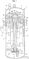
Fig. 1 is a longitudinal sectional view illustrating a scroll-type compressor according to an embodiment of the present invention. -
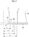
Fig. 2 is a partially enlarged longitudinal sectional view illustrating a thrust plate of the scroll-type compressor according to the embodiment of the present invention. -
Fig. 3 is a plan view illustrating the thrust plate of the scroll-type compressor according to the embodiment of the present invention. -
Fig. 4 is a longitudinal sectional view illustrating an example of a groove formed in the thrust plate of the scroll-type compressor according to the embodiment of the present invention. -
Fig. 5 is a longitudinal sectional view illustrating an example of the groove formed in the thrust plate of the scroll-type compressor according to the embodiment of the present invention. -
Fig. 6 is a longitudinal sectional view illustrating an example of the groove formed in the thrust plate of the scroll-type compressor according to the embodiment of the present invention. -
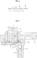
Fig. 7 is a longitudinal sectional view illustrating a lower end portion of a crankshaft, the thrust plate, and a suction pipe of the scroll-type compressor according to the embodiment of the present invention. -
Fig. 8 is a graph illustrating the efficiency of an air conditioning device for each operation mode or for each performance evaluation. -
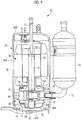
Fig. 9 is a longitudinal sectional view illustrating a rotary compressor according to an embodiment of the present invention. - Hereinafter, a hermetic scroll compressor according to an embodiment of the present invention will be described with reference to the drawings.
- As illustrated in
Fig. 1 , ahermetic scroll compressor 1 as a scroll fluid machine includes a vertically long cylindricalhermetic housing 2 whose bottom portion is hermetic by a lower cover. An upper part of thehermetic housing 2 is hermetic by a discharge cover 3 and an upper cover 4, adischarge chamber 5 for discharging compressed high-pressure gas is formed between the discharge cover 3 and the upper cover 4. - Inside the
hermetic housing 2, an upper bearing member (frame member) 6 is fixedly installed in the upper part, a scroll compression mechanism 7 is incorporated via the upper bearingmember 6, and anelectric motor 10 having astator 8 and arotor 9 is installed in the lower part. Theelectric motor 10 is incorporated by thestator 8 fixedly installed in thehermetic housing 2, and acrankshaft 11 is fixed to therotor 9. - An upper end of the
crankshaft 11 has acrank pin 12 whose axis is eccentric as much as a predetermined dimension. Thecrank pin 12 is connected to the scroll compression mechanism 7, thereby enabling the scroll compression mechanism 7 to be driven by theelectric motor 10. Thecrankshaft 11 is supported by ajournal bearing portion 6A of the upper bearingmember 6 so that an upper portion is rotatable, and a lower end portion is rotatably supported by a lower journal bearing 13 disposed in the lower part of thehermetic housing 2. - A displacement-type
oil supply pump 14 is disposed between the lower journal bearing 13 and the lower end portion of thecrankshaft 11, and thelubricant 15 filling the bottom portion of thehermetic housing 2 is suctioned via asuction pipe 16. Thelubricant 15 is configured to be discharged to acirculation passage 17 drilled inside thecrankshaft 11 along an axial direction. Thelubricant 15 can be supplied via thecirculation passage 17 to portions requiring lubrication, such as the upper bearingmember 6, the scroll compression mechanism 7, and the lower journal bearing 13. - The scroll compression mechanism 7 has the
upper bearing member 6 serving as one configuration component, and includes a fixedscroll 18 fixedly installed on theupper bearing member 6, an orbitingscroll 19 that is slidably supported by athrust bearing portion 6B of theupper bearing member 6, and that forms acompression chamber 20 by meshing with the fixedscroll 18, arotation prevention mechanism 21 such as an Oldham ring that is interposed between theupper bearing member 6 and the orbitingscroll 19, and that prevents rotation of the orbitingscroll 19 and allows orbital turning movement, and adrive bush 22 and a turning bearing (needle bearing) 23 which are disposed between thecrank pin 12 of thecrankshaft 11 and abearing boss 19C disposed on a rear surface the orbitingscroll 19, and which transmit a rotational force of thecrankshaft 11 to theorbiting scroll 19. The scroll compression mechanism 7 is installed on theupper bearing member 6 in a state where a central portion of an end plate of the fixedscroll 18 is connected to the discharge cover 3. - The fixed
scroll 18 includes anend plate 18A and aspiral wrap 18B erected on theend plate 18A, and is configured so that adischarge port 24 is disposed in a central portion of theend plate 18A, and so that atip seal 25 is installed on a wrap tooth tip surface of thespiral wrap 18B. In addition, the orbitingscroll 19 includes anend plate 19A and aspiral wrap 19B erected on theend plate 19A. A bearingboss 19C is disposed on a rear surface of theend plate 19A, and atip seal 26 is installed on a wrap tooth tip surface of thespiral wrap 19B. - The scroll compression mechanism 7 suctions refrigerant gas suctioned into the
hermetic housing 2 via asuction pipe 27 open at a position facing a stator winding 8A of theelectric motor 10, into thecompression chamber 20 from asuction port 28 open in thehermetic housing 2, and compresses the refrigerant gas into high-temperature and high-pressure gas. The compressed gas is discharged into thedischarge chamber 5 via adischarge port 24 disposed in a central portion of the fixedscroll 18 and adischarge valve 29 disposed in the discharge cover 3, and further, the compressed gas is fed outward of the compressor via adischarge pipe 30 connected to thedischarge chamber 5. - Hereinafter, referring to
Figs. 2 to 7 , athrust plate 40 disposed in the compressor according to the present embodiment will be described. - The
thrust plate 40 is a plate member disposed so as to be in contact with a lower end surface of thecrankshaft 11. For example, thethrust plate 40 has a thickness of approximately 1 mm. Thethrust plate 40 is installed between a lower surface of the lower journal bearing 13 and an upper surface of thesuction pipe 16. - The
thrust plate 40 has a through-hole 41 through which thelubricant 15 is circulated. The through-hole 41 causes acirculation passage 51 formed in thesuction pipe 16 to communicate with thecirculation passage 17 formed in thecrankshaft 11. As a result, as illustrated inFig. 7 , thelubricant 15 passing through thesuction pipe 16 is circulated through the through-hole 41 of thethrust plate 40. After thelubricant 15 is circulated through the through-hole 41 of thethrust plate 40 to thelubricant 15, thelubricant 15 flows in thecirculation passage 17 of thecrankshaft 11. - In the
thrust plate 40, agroove 42 is formed in a sliding region between thecrankshaft 11 and thethrust plate 40. The sliding region between thecrankshaft 11 and thethrust plate 40 is a region where the lower end surface of thecrankshaft 11 and the upper surface of thethrust plate 40 face each other. Hereinafter, a case will be described where thegroove 42 is formed only in thethrust plate 40. However, the present invention is not limited to this example. For example, the groove according to the invention may be formed only in thecrankshaft 11 in the sliding region between thecrankshaft 11 and thethrust plate 40, or may be formed in both thecrankshaft 11 and thethrust plate 40. - The
groove 42 is formed in a recess shape in thethrust plate 40, and thelubricant 15 is supplied from the through-hole 41. That is, thegroove 42 communicates with thecirculation passage 51 formed in thesuction pipe 16 and thecirculation passage 17 formed in thecrankshaft 11 on the through-hole 41 side of thethrust plate 40. - A minute recess is formed in the
thrust plate 40. In this manner, dynamic pressure is generated in the sliding region, and floating occurs due to oil film pressure. As a result, friction loss occurring between the lower end surface of thecrankshaft 11 and the upper surface of thethrust plate 40 can be reduced. - For example, a depth of the
groove 42 is 5 µm to 10 µm. The depth of thegroove 42 is determined depending on a ratio (A-value) between the thickness of the oil film generated between the lower end surface of thecrankshaft 11 and the upper surface of thethrust plate 40 and composite roughness of the sliding surface. When the Λ-value (= thickness of oil film / composite roughness of sliding surface) is greater than 3, it is known that floating caused by the oil film surely occurs, and the oil film enables thecrankshaft 11 to float with respect to thethrust plate 40. In addition, irrespective of whether the rotation speed of thecrankshaft 11 is high or low, if the depth of thegroove 42 is too shallow or too deep, the A-value becomes a low value. That is, irrespective of whether the rotation speed of thecrankshaft 11 is high or low, there is an optimum depth of thegroove 42 where the A-value becomes a maximum value. - In a case where the rotation speed of the
crankshaft 11 is low, if thegroove 42 is deep, the Λ-value tends to be 3 or less. In contrast, in a case where the rotation speed of thecrankshaft 11 is high, even if thegroove 42 is deep, the Λ-value can be maintained at a value greater than 3. That is, in a case where the rotation speed of thecrankshaft 11 is low, a range of the depth of thegroove 42 in which the Λ-value can be greater than 3 is narrower than a range in a case where the rotation speed of thecrankshaft 11 is high. - In the compressor, when the diameter of the
crankshaft 11 is set to 10 mm to 40 mm, the rotation speed of thecrankshaft 11 is 10 set to 10 rps to 140 rps, lubricant viscosity is set to 2 mPa·s to 30 mPa·s, and a total dead weight of thecrankshaft 11 and therotor 9 is set to 10 N to 100 N, the inventors perform analysis for calculating the Λ-value. As a result, the inventors confirm that the range of the depth of thegroove 42 of thethrust plate 40 is desirably in the range of 5 µm to 10 µm. - In addition, based on the demonstration experiments, the inventors confirm the following. When the rotation speed of the
crankshaft 11 is relatively low, for example, in a case where the rotation speed is lower than 40 rps, the depth of thegroove 42 is desirably 5 µm. When the rotation speed of thecrankshaft 11 is relatively high, for example, in a case where the rotation speed is equal to or higher than 90 rps, the depth of thegroove 42 is preferably 10 µm. This result indicates the same tendency as the above-described analysis for calculating the A-value. - For example,
Fig. 8 illustrates a graph when total efficiency of the compressor is set to 1 in a case where the thrust plate having nogroove 42 is disposed during an intermediate cooling operation. As a result, during the intermediate cooling operation in which the rotation speed of thecrankshaft 11 is relatively low, the efficiency in a case where the depth of thegroove 42 is set to 5 µm is higher than that in a case where the depth of thegroove 42 is set to 10 µm. On the other hand, during a rated heating operation in which the rotation speed of thecrankshaft 11 is relatively high, the efficiency in a case where the depth of thegroove 42 is set to 10 µm is higher than that in a case where the depth of thegroove 42 is set to 5 µm. - That is, in a case where an energy-saving performance of an air conditioning device is evaluated using an annual performance factor (APF) whose weighting during the intermediate operation is higher than that during the rated operation, the depth of the
groove 42 is desirably set to 5 µm rather than 10 µm. - The
outer end portion 42a of thegroove 42 in the radial direction is located inward of the outermost peripheral portion in the sliding region of thecrankshaft 11 and thethrust plate 40. That is, thegroove 42 does not communicate with a portion from the inside to the outermost peripheral portion in the radial direction of the sliding region. Therefore, thelubricant 15 supplied from the through-hole 41 to thegroove 42 is likely to stay in thegroove 42, and is less likely to leak to the outer peripheral side from the sliding region. - Unlike in the present embodiment, in a case where the
groove 42 is formed to entirely penetrate in the radial direction of the sliding region, that is, from the inner peripheral portion to the outer peripheral portion, thelubricant 15 leaks out of the circulation system, the amount of thelubricant 15 supplied to the journal bearing or the compression mechanism decreases. In contrast, in a case of the present embodiment, thegroove 42 does not communicate with the portion from the inside to the outermost peripheral portion in the radial direction of the sliding region. Accordingly, without reducing the amount of thelubricant 15, thelubricant 15 can be sufficiently supplied to the journal bearing or the compression mechanism. - The
outer end portion 42a of thegroove 42 in the radial direction is located inward as much as approximately 10% of the radius of the outermost peripheral portion in the above-described sliding region. In this manner, it is possible to reliably prevent thelubricant 15 supplied to thegroove 42 from leaking from the inner peripheral side to the outer peripheral side of the sliding region. - The
outer end portion 42a of thegroove 42 in the radial direction is located outward of an intermediate position between the innermost peripheral portion and the outermost peripheral portion in the sliding region. In this manner, thegroove 42 can supply thelubricant 15 to the outside from the intermediate position between the innermost peripheral portion and the outermost peripheral portion in the sliding region. - The above-described relationship can be expressed by the following expression.

- Here, r is the radius of the
outer end portion 42a of thegroove 42, that is, the radius of a boundary portion having a step difference formed therein, rout is the radius of the outermost peripheral portion in the sliding region, and rin is the radius of the innermost peripheral portion in the sliding region. - In addition, an area of the region having the
groove 42 formed in the sliding region is desirably set to 50% to 80% of the total area of the sliding region inside theouter end portion 42a in the radial direction of thegroove 42. - If an area of the region having the
groove 42 formed in the sliding region is set to Astep and an area of the region (land region) having nogroove 42 inside theouter end portion 42a in the radial direction of thegroove 42 in the sliding region is set to Aland, the relationship is expressed by the following expression.
- Since this condition is satisfied, dynamic pressure is generated in the sliding region, and floating occurs due to oil film pressure. In the example illustrated in
Fig. 3 , thegroove 42 has a fan shape having a center angle of 60°, and is disposed at four positions for every angle of 90° in the circumferential direction. Accordingly, Astep/(Astep+ Aland) is 0.67. - In addition, as illustrated in
Fig. 2 , atapered surface 43 is formed in a portion facing the inner portion of thegroove 42 in the radial direction in thecrankshaft 11. In this way, the taperedsurface 43 is formed on a side where thelubricant 15 is introduced in thegroove 42. Accordingly, the inside of thegroove 42 in the radial direction is widened in the height direction, and thus, thelubricant 15 is likely to be supplied into thegroove 42. In the present invention, without being limited to a case where the tapered surface is formed in the portion facing the groove, the tapered surface may also be disposed in the inner peripheral portion of the groove. Even in this case, thelubricant 15 is likely to be supplied into the groove. - For example, a sectional shape taken along the circumferential direction of the
groove 42 has a stepped shape (Fig. 4 ), a tapered shape (Fig. 5 ), or a dimple shape (Fig. 6 ). That is, a general shape used in the thrust bearing can also be applied to the present embodiment. - As illustrated in
Figs. 2 and7 , apump rotor 45 of the displacement-typeoil supply pump 14 is disposed outside the sliding region. Then, the lower surface of thecrankshaft 11 is flush with the lower surface of thepump rotor 45. Accordingly, even if thelubricant 15 slightly leaks from thecrankshaft 11 and the sliding region of thethrust plate 40, thelubricant 15 can lubricate a portion between the lower surface of thepump rotor 45 and the upper surface of the thrust plate. In this case, it is possible to improve the efficiency of the displacement-typeoil supply pump 14. - As described above, according to the present embodiment, the through-
hole 41 is formed in thethrust plate 40, thecirculation passage 17 is formed inside thecrankshaft 11 placed on the upper surface of thethrust plate 40. After thelubricant 15 is circulated through the through-hole 41 of thethrust plate 40, thelubricant 15 flows in thecirculation passage 17 of thecrankshaft 11. In thecrankshaft 11 and the sliding region of thethrust plate 40, thegroove 42 is formed in thethrust plate 40, and thelubricant 15 is supplied to thegroove 42 from the through-hole 41. As a result, thecrankshaft 11 and the sliding region of thethrust plate 40 thelubricant 15 are filled with thelubricant 15 so as to form the oil film. In this manner, the friction loss can be reduced. In addition, theouter end portion 42a of thegroove 42 in the radial direction is located inward of the outermost peripheral portion in the above-described sliding region. Accordingly, thelubricant 15 supplied to thegroove 42 is less likely to leak from the inner peripheral side to the outer peripheral side of the sliding region. - Therefore, the friction loss can be reduced. Moreover, without reducing the amount of the
lubricant 15, it is possible to sufficiently supply thelubricant 15 to the journal bearing or the compression mechanism. As a result, it is possible to achieve the highly efficient compressor and to improve the reliability of the compressor. - In the above-described embodiment, a case of the scroll-type compressor has been described. However, the present invention is not limited to this example. For example, the present invention is also applicable to a rotary compressor or a reciprocating-type compressor. Furthermore, the fluid machine according to the present invention is not limited to the compressor, and is also applicable to an expansion machine.
- Hereinafter, a case will be described where the
thrust plate 40 according to the present embodiment is applied to the rotary compressor. -
Fig. 9 is a longitudinal sectional view illustrating a configuration example of a hermetic single cylinder as an example of the rotary compressor. For the sake of convenience, hereinafter, an embodiment applied to the single cylinder rotary compressor will be described. However, as a matter of course, the present invention is similarly applicable to not only a double cylinder rotary compressor, but also a rotary compression mechanism of the compressor having a plurality of different compression mechanisms. - A
hermetic rotary compressor 61 includes ahousing 62 having a hermetic structure. Thehousing 62 is configured to include acylindrical center housing 62A, anupper housing 62B hermetically closing an upper portion of thecenter housing 62A, and alower housing 62C hermetically closing a lower portion of thecenter housing 62A. On the upper portion side inside thecenter housing 62A, anelectric motor 64 having astator 65 and arotor 66 is fixedly installed as a drive source.
In addition, therotor 66 is integrally combined with a crankshaft (rotary shaft) 67. - A single cylinder
rotary compression mechanism 63 is installed in the lower portion of theelectric motor 64. Therotary compression mechanism 63 is configured to include a cylindermain body 69 having acylinder chamber 68 formed therein, anupper bearing 70 and alower bearing 71 which are fixedly installed in the upper portion and the lower portion of the cylindermain body 69 and which hermetically close the upper portion and the lower portion of thecylinder chamber 68, arotor 72 which is fitted to aneccentric part 67A of thecrankshaft 67 and is rotated on the inner peripheral surface of thecylinder chamber 68, and a blade and a blade pressing spring (not illustrated) which partition the inside of thecylinder chamber 68 into a suction side and a discharge side. - In this
rotary compression mechanism 63, either the cylindermain body 69 or theupper bearing 70 is fixedly installed on the inner peripheral surface of thecenter housing 62A at a plurality of circumferential locations by means of plug welding or caulking. Other members are integrally assembled to the fixedly installed member. - The
rotary compression mechanism 63 suctions low-pressure refrigerant gas of the compressed fluid from an accumulator 74 integrated with therotary compressor 61 into thecylinder chamber 68 via asuction pipe 73, and compresses the refrigerant gas by rotating therotor 72. Thereafter, the compressed refrigerant gas is discharged into anupper muffler chamber 75 and alower muffler chamber 76 which are formed using theupper bearing 70 and thelower bearing 71. A configuration is adopted as follows. The high-pressure refrigerant gas compressed in this way is merged in theupper muffler chamber 75, and thereafter, is discharged into thecenter housing 62A. The inside of theupper muffler chamber 75 and thelower muffler chamber 76 and the inside of thecenter housing 62A are in a state where all of these substantially have no pressure difference. - The high-pressure refrigerant gas is circulated through a gas passage hole (not illustrated) disposed around the
electric motor 64, and is guided to an upper space of theelectric motor 64. Furthermore, the high-pressure refrigerant gas is fed to the outside of therotary compressor 61, that is, to the refrigerating cycle side via adischarge pipe 77. - In the
rotary compression mechanism 63, the cylindermain body 69, theupper bearing 70 and thelower bearing 71 which are disposed above and below the cylindermain body 69, and the lower muffler 7A forming thelower muffler chamber 76 below thelower bearing 71 are integrated with each other by means of screw fastening of thebolt 78 penetrating in the axial direction of thecrankshaft 67. - Both the
upper muffler chamber 75 and thelower muffler chamber 76 have no difference between internal pressure and external pressure. However, in the illustrated configuration example, sealing performance against thelubricant 15 is required. Accordingly, only thelower muffler 76A is fastened by thebolt 78. However, both theupper muffler 75A and thelower muffler 76A may adopt a structure in which both of these are fastened by thebolt 78 or a structure in which any one of these is fastened by thebolt 78. The present embodiment is not particularly limited thereto. - Here, the
thrust plate 40 is a plate member disposed so as to be in contact with the lower end surface of thecrankshaft 67. For example, thethrust plate 40 has a thickness of approximately 1 mm. Thethrust plate 40 is installed between the lower surface of the lower journal bearing 13 and the upper surface of thelower muffler 76A. - A centrifugal lubrication pump (not illustrated) is disposed in the lower end portion of the
crankshaft 67, and thelubricant 15 filling in the bottom portion of thehousing 62 is suctioned via the centrifugal lubrication pump. Thelubricant 15 is configured to be discharged to a circulation passage (not illustrated) drilled into thecrankshaft 67 along the axial direction. Thelubricant 15 can be supplied via the circulation passage to portions requiring lubrication, such as theupper bearing 70 and thelower bearing 71. - In the
thrust plate 40, thegroove 42 is formed in the sliding region between thecrankshaft 67 and thethrust plate 40. Thegroove 42 is formed in a recess shape in thethrust plate 40, and thelubricant 15 is supplied from the through-hole 41. That is, thegroove 42 communicates with the centrifugal lubrication pump and the circulation passage formed in thecrankshaft 67. Even in a case of therotary compressor 61, thethrust plate 40 having the same configuration as that described in thescroll compressor 1 is disposed. Then, thecrankshaft 67 and the sliding region of thethrust plate 40 are filled with thelubricant 15 so as to form the oil film. In this manner, the friction loss can be reduced. In addition, theouter end portion 42a of thegroove 42 in the radial direction is located inward of the outermost peripheral portion in the above-described sliding region. Accordingly, thelubricant 15 supplied to thegroove 42 is less likely to leak from the inner peripheral side to the outer peripheral side of the sliding region. - Therefore, the friction loss can be reduced. Moreover, without reducing the amount of the
lubricant 15, it is possible to sufficiently supply thelubricant 15 to the journal bearing or the compression mechanism. As a result, it is possible to achieve the highly efficient compressor and to improve the reliability of the compressor. Detailed configurations and operation effects will be omitted since these have repeated content described in thescroll compressor 1. -
- 1:
- HERMETIC SCROLL COMPRESSOR
- 2:
- HERMETIC HOUSING
- 3:
- DISCHARGE COVER
- 4:
- UPPER COVER
- 5:
- DISCHARGE CHAMBER
- 6:
- UPPER BEARING MEMBER
- 6A:
- JOURNAL BEARING PORTION
- 6B:
- THRUST BEARING PORTION
- 7:
- SCROLL COMPRESSION MECHANISM
- 7A:
- LOWER MUFFLER
- 8:
- STATOR
- 8A:
- STATOR WINDING
- 9:
- ROTOR
- 10:
- ELECTRIC MOTOR
- 11:
- CRANKSHAFT
- 12:
- CRANK PIN
- 13:
- LOWER JOURNAL BEARING
- 14:
- DISPLACEMENT-TYPE OIL SUPPLY PUMP
- 15:
- LUBRICANT
- 16:
- SUCTION PIPE
- 17:
- CIRCULATION PASSAGE
- 18:
- FIXED SCROLL
- 18A:
- END PLATE
- 18B:
- SPIRAL WRAP
- 19:
- ORBITING SCROLL
- 19A:
- END PLATE
- 19B:
- SPIRAL WRAP
- 19C:
- BEARING BOSS
- 20:
- COMPRESSION CHAMBER
- 21:
- ROTATION PREVENTION MECHANISM
- 22:
- DRIVE BUSH
- 24:
- DISCHARGE PORT
- 25:
- TIP SEAL
- 26:
- TIP SEAL
- 27:
- SUCTION PIPE
- 28:
- SUCTION PORT
- 29:
- DISCHARGE VALVE
- 30:
- DISCHARGE PIPE
- 40:
- THRUST PLATE
- 41:
- THROUGH-HOLE
- 42:
- GROOVE
- 42a:
- OUTER END PORTION
- 45:
- PUMP ROTOR
- 51:
- CIRCULATION PASSAGE
- 61:
- ROTARY COMPRESSOR
- 62:
- HOUSING
- 62A:
- CENTER HOUSING
- 62B:
- UPPER HOUSING
- 62C:
- LOWER HOUSING
- 63:
- ROTARY COMPRESSION MECHANISM
- 64:
- ELECTRIC MOTOR
- 65:
- STATOR
- 66:
- ROTOR
- 67:
- CRANKSHAFT
- 67A:
- ECCENTRIC PART
- 68:
- CYLINDER CHAMBER
- 69:
- CYLINDER MAIN BODY
- 70:
- UPPER BEARING
- 71:
- LOWER BEARING
- 72:
- ROTOR
- 73:
- SUCTION PIPE
- 74:
- ACCUMULATOR
- 75:
- UPPER MUFFLER CHAMBER
- 75A:
- AN UPPER MUFFLER
- 76:
- LOWER MUFFLER CHAMBER
- 76A:
- LOWER MUFFLER
- 77:
- DISCHARGE PIPE
- 78:
- BOLT
Claims (5)
- A fluid machine comprising:an annular plate part that has a through-hole through which a lubricant is circulated; anda crankshaft that is placed on an upper surface of the plate part, and that internally has a circulation passage for circulating the lubricant passing through the through-hole of the plate part,wherein in sliding region between the crankshaft and the plate part, at least one of the crankshaft and the plate part has a recess groove to which the lubricant is supplied from the through-hole, andwherein an outer end portion of the groove in a radial direction is located inward of an outermost peripheral portion in the sliding region.
- The fluid machine according to Claim 1,
wherein the outer end portion of the groove in the radial direction is located outward of an intermediate position between an innermost peripheral portion and the outermost peripheral portion in the sliding region. - The fluid machine according to Claim 1 or 2,
wherein an area of a region having the groove in the sliding region is 50% to 80% of a total area located inward of the outer end portion of the groove in the radial direction in the sliding region. - The fluid machine according to any one of Claims 1 to 3,
wherein an inner portion of the groove in the radial direction or a portion facing the inner portion of the groove in the radial direction in the crankshaft or the plate part has a tapered surface. - The fluid machine according to any one of Claims 1 to 4,
wherein the groove has a stepped shape, a tapered shape, or a dimple shape.
Applications Claiming Priority (2)
| Application Number | Priority Date | Filing Date | Title |
|---|---|---|---|
| JP2016042113A JP6758867B2 (en) | 2016-03-04 | 2016-03-04 | Fluid machine |
| PCT/JP2017/008086 WO2017150603A1 (en) | 2016-03-04 | 2017-03-01 | Fluid machine |
Publications (3)
| Publication Number | Publication Date |
|---|---|
| EP3369931A1 true EP3369931A1 (en) | 2018-09-05 |
| EP3369931A4 EP3369931A4 (en) | 2018-12-12 |
| EP3369931B1 EP3369931B1 (en) | 2021-03-31 |
Family
ID=59742967
Family Applications (1)
| Application Number | Title | Priority Date | Filing Date |
|---|---|---|---|
| EP17760067.3A Active EP3369931B1 (en) | 2016-03-04 | 2017-03-01 | Fluid machine |
Country Status (4)
| Country | Link |
|---|---|
| EP (1) | EP3369931B1 (en) |
| JP (1) | JP6758867B2 (en) |
| CN (1) | CN108350869B (en) |
| WO (1) | WO2017150603A1 (en) |
Families Citing this family (5)
| Publication number | Priority date | Publication date | Assignee | Title |
|---|---|---|---|---|
| CN113330215B (en) * | 2019-01-31 | 2023-02-17 | 三菱电机株式会社 | Sliding bearing structure and scroll compressor |
| JP7608042B2 (en) * | 2019-03-28 | 2025-01-06 | 三菱重工サーマルシステムズ株式会社 | Compressor |
| JP2022026427A (en) * | 2020-07-31 | 2022-02-10 | 株式会社小松製作所 | Guidance device |
| DE112021006747T5 (en) * | 2021-01-04 | 2023-11-02 | Siam Compressor Industry Co., Ltd. | compressor |
| CN117365904A (en) * | 2023-10-07 | 2024-01-09 | 安徽科海压缩机制造有限公司 | Compressor crank structure and processing device |
Family Cites Families (8)
| Publication number | Priority date | Publication date | Assignee | Title |
|---|---|---|---|---|
| US3182901A (en) * | 1963-11-12 | 1965-05-11 | Westinghouse Electric Corp | Compressor |
| JPS5118486Y2 (en) * | 1971-05-24 | 1976-05-17 | ||
| US3830341A (en) * | 1972-11-24 | 1974-08-20 | Carrier Corp | Lubrication system for a motor compressor unit |
| US3926281A (en) * | 1974-03-21 | 1975-12-16 | Tecumseh Products Co | Compressor oil pump with filter |
| US4131396A (en) * | 1977-04-07 | 1978-12-26 | Sundstrand Corporation | Hermetic compressor lubrication system with two-stage oil pump |
| US4325679A (en) * | 1980-07-22 | 1982-04-20 | White Consolidated Industries, Inc. | Oil pump for hermetic compressor |
| JPS5911184U (en) * | 1982-07-13 | 1984-01-24 | ダイキン工業株式会社 | Lubrication mechanism of hermetic compressor |
| JP5370450B2 (en) * | 2011-09-28 | 2013-12-18 | ダイキン工業株式会社 | Compressor |
-
2016
- 2016-03-04 JP JP2016042113A patent/JP6758867B2/en active Active
-
2017
- 2017-03-01 CN CN201780003768.6A patent/CN108350869B/en active Active
- 2017-03-01 EP EP17760067.3A patent/EP3369931B1/en active Active
- 2017-03-01 WO PCT/JP2017/008086 patent/WO2017150603A1/en not_active Ceased
Also Published As
| Publication number | Publication date |
|---|---|
| CN108350869A (en) | 2018-07-31 |
| EP3369931B1 (en) | 2021-03-31 |
| WO2017150603A1 (en) | 2017-09-08 |
| CN108350869B (en) | 2020-03-24 |
| EP3369931A4 (en) | 2018-12-12 |
| JP2017155718A (en) | 2017-09-07 |
| JP6758867B2 (en) | 2020-09-23 |
Similar Documents
| Publication | Publication Date | Title |
|---|---|---|
| EP3369931B1 (en) | Fluid machine | |
| US9316225B2 (en) | Scroll compressor with thrust sliding surface oiling groove | |
| EP1260713A2 (en) | Scroll compressor with Oldham coupling | |
| US20010026766A1 (en) | Scroll compressor | |
| WO2007111903A1 (en) | Scroll machine using floating seal with backer | |
| US6179591B1 (en) | Conical hub bearing for scroll machine | |
| CN105736372B (en) | Rotary compressor | |
| JP5145252B2 (en) | Scroll compressor and refueling method of scroll compressor | |
| CN205714768U (en) | Rotary compressor | |
| JP3274900B2 (en) | Refueling pump device in compressor | |
| US4993929A (en) | Scroll machine with lubricated thrust surfaces | |
| JP2616066B2 (en) | Scroll compressor | |
| JP4024521B2 (en) | Scroll compressor | |
| JP2009097357A (en) | Hermetic scroll compressor | |
| JPWO2004029461A1 (en) | Scroll compressor | |
| JPH0727061A (en) | Scroll compressor | |
| EP4098877B1 (en) | Scroll compressor | |
| WO2018198811A1 (en) | Rolling-cylinder-type displacement compressor | |
| JP3455640B2 (en) | Fluid compressor | |
| JPH11351172A (en) | Fluid machinery | |
| JP2001329957A (en) | Positive displacement fluid machinery | |
| JP2011137523A (en) | Rotary shaft and compressor | |
| WO2022264792A1 (en) | Scroll compressor | |
| CN116085263A (en) | Compressor oil storage structure and compressor | |
| AU2015300143B2 (en) | Open-type compressor |
Legal Events
| Date | Code | Title | Description |
|---|---|---|---|
| STAA | Information on the status of an ep patent application or granted ep patent |
Free format text: STATUS: THE INTERNATIONAL PUBLICATION HAS BEEN MADE |
|
| PUAI | Public reference made under article 153(3) epc to a published international application that has entered the european phase |
Free format text: ORIGINAL CODE: 0009012 |
|
| STAA | Information on the status of an ep patent application or granted ep patent |
Free format text: STATUS: REQUEST FOR EXAMINATION WAS MADE |
|
| 17P | Request for examination filed |
Effective date: 20180601 |
|
| AK | Designated contracting states |
Kind code of ref document: A1 Designated state(s): AL AT BE BG CH CY CZ DE DK EE ES FI FR GB GR HR HU IE IS IT LI LT LU LV MC MK MT NL NO PL PT RO RS SE SI SK SM TR |
|
| AX | Request for extension of the european patent |
Extension state: BA ME |
|
| RIC1 | Information provided on ipc code assigned before grant |
Ipc: F04C 29/02 20060101ALI20181031BHEP Ipc: F04B 39/02 20060101AFI20181031BHEP |
|
| A4 | Supplementary search report drawn up and despatched |
Effective date: 20181109 |
|
| DAV | Request for validation of the european patent (deleted) | ||
| DAX | Request for extension of the european patent (deleted) | ||
| STAA | Information on the status of an ep patent application or granted ep patent |
Free format text: STATUS: EXAMINATION IS IN PROGRESS |
|
| 17Q | First examination report despatched |
Effective date: 20190813 |
|
| GRAP | Despatch of communication of intention to grant a patent |
Free format text: ORIGINAL CODE: EPIDOSNIGR1 |
|
| STAA | Information on the status of an ep patent application or granted ep patent |
Free format text: STATUS: GRANT OF PATENT IS INTENDED |
|
| RIC1 | Information provided on ipc code assigned before grant |
Ipc: F04C 18/02 20060101ALI20200925BHEP Ipc: F04C 23/00 20060101ALI20200925BHEP Ipc: F04C 29/02 20060101ALI20200925BHEP Ipc: F04B 39/02 20060101AFI20200925BHEP |
|
| INTG | Intention to grant announced |
Effective date: 20201020 |
|
| GRAS | Grant fee paid |
Free format text: ORIGINAL CODE: EPIDOSNIGR3 |
|
| GRAA | (expected) grant |
Free format text: ORIGINAL CODE: 0009210 |
|
| STAA | Information on the status of an ep patent application or granted ep patent |
Free format text: STATUS: THE PATENT HAS BEEN GRANTED |
|
| AK | Designated contracting states |
Kind code of ref document: B1 Designated state(s): AL AT BE BG CH CY CZ DE DK EE ES FI FR GB GR HR HU IE IS IT LI LT LU LV MC MK MT NL NO PL PT RO RS SE SI SK SM TR |
|
| REG | Reference to a national code |
Ref country code: GB Ref legal event code: FG4D Ref country code: CH Ref legal event code: EP |
|
| REG | Reference to a national code |
Ref country code: AT Ref legal event code: REF Ref document number: 1377225 Country of ref document: AT Kind code of ref document: T Effective date: 20210415 |
|
| REG | Reference to a national code |
Ref country code: DE Ref legal event code: R096 Ref document number: 602017035752 Country of ref document: DE |
|
| REG | Reference to a national code |
Ref country code: IE Ref legal event code: FG4D |
|
| REG | Reference to a national code |
Ref country code: LT Ref legal event code: MG9D |
|
| PG25 | Lapsed in a contracting state [announced via postgrant information from national office to epo] |
Ref country code: BG Free format text: LAPSE BECAUSE OF FAILURE TO SUBMIT A TRANSLATION OF THE DESCRIPTION OR TO PAY THE FEE WITHIN THE PRESCRIBED TIME-LIMIT Effective date: 20210630 Ref country code: NO Free format text: LAPSE BECAUSE OF FAILURE TO SUBMIT A TRANSLATION OF THE DESCRIPTION OR TO PAY THE FEE WITHIN THE PRESCRIBED TIME-LIMIT Effective date: 20210630 Ref country code: FI Free format text: LAPSE BECAUSE OF FAILURE TO SUBMIT A TRANSLATION OF THE DESCRIPTION OR TO PAY THE FEE WITHIN THE PRESCRIBED TIME-LIMIT Effective date: 20210331 Ref country code: HR Free format text: LAPSE BECAUSE OF FAILURE TO SUBMIT A TRANSLATION OF THE DESCRIPTION OR TO PAY THE FEE WITHIN THE PRESCRIBED TIME-LIMIT Effective date: 20210331 |
|
| PG25 | Lapsed in a contracting state [announced via postgrant information from national office to epo] |
Ref country code: LV Free format text: LAPSE BECAUSE OF FAILURE TO SUBMIT A TRANSLATION OF THE DESCRIPTION OR TO PAY THE FEE WITHIN THE PRESCRIBED TIME-LIMIT Effective date: 20210331 Ref country code: RS Free format text: LAPSE BECAUSE OF FAILURE TO SUBMIT A TRANSLATION OF THE DESCRIPTION OR TO PAY THE FEE WITHIN THE PRESCRIBED TIME-LIMIT Effective date: 20210331 Ref country code: SE Free format text: LAPSE BECAUSE OF FAILURE TO SUBMIT A TRANSLATION OF THE DESCRIPTION OR TO PAY THE FEE WITHIN THE PRESCRIBED TIME-LIMIT Effective date: 20210331 |
|
| REG | Reference to a national code |
Ref country code: NL Ref legal event code: MP Effective date: 20210331 |
|
| REG | Reference to a national code |
Ref country code: AT Ref legal event code: MK05 Ref document number: 1377225 Country of ref document: AT Kind code of ref document: T Effective date: 20210331 |
|
| PG25 | Lapsed in a contracting state [announced via postgrant information from national office to epo] |
Ref country code: CZ Free format text: LAPSE BECAUSE OF FAILURE TO SUBMIT A TRANSLATION OF THE DESCRIPTION OR TO PAY THE FEE WITHIN THE PRESCRIBED TIME-LIMIT Effective date: 20210331 Ref country code: EE Free format text: LAPSE BECAUSE OF FAILURE TO SUBMIT A TRANSLATION OF THE DESCRIPTION OR TO PAY THE FEE WITHIN THE PRESCRIBED TIME-LIMIT Effective date: 20210331 Ref country code: LT Free format text: LAPSE BECAUSE OF FAILURE TO SUBMIT A TRANSLATION OF THE DESCRIPTION OR TO PAY THE FEE WITHIN THE PRESCRIBED TIME-LIMIT Effective date: 20210331 Ref country code: AT Free format text: LAPSE BECAUSE OF FAILURE TO SUBMIT A TRANSLATION OF THE DESCRIPTION OR TO PAY THE FEE WITHIN THE PRESCRIBED TIME-LIMIT Effective date: 20210331 Ref country code: NL Free format text: LAPSE BECAUSE OF FAILURE TO SUBMIT A TRANSLATION OF THE DESCRIPTION OR TO PAY THE FEE WITHIN THE PRESCRIBED TIME-LIMIT Effective date: 20210331 Ref country code: SM Free format text: LAPSE BECAUSE OF FAILURE TO SUBMIT A TRANSLATION OF THE DESCRIPTION OR TO PAY THE FEE WITHIN THE PRESCRIBED TIME-LIMIT Effective date: 20210331 |
|
| PG25 | Lapsed in a contracting state [announced via postgrant information from national office to epo] |
Ref country code: IS Free format text: LAPSE BECAUSE OF FAILURE TO SUBMIT A TRANSLATION OF THE DESCRIPTION OR TO PAY THE FEE WITHIN THE PRESCRIBED TIME-LIMIT Effective date: 20210731 Ref country code: PT Free format text: LAPSE BECAUSE OF FAILURE TO SUBMIT A TRANSLATION OF THE DESCRIPTION OR TO PAY THE FEE WITHIN THE PRESCRIBED TIME-LIMIT Effective date: 20210802 Ref country code: PL Free format text: LAPSE BECAUSE OF FAILURE TO SUBMIT A TRANSLATION OF THE DESCRIPTION OR TO PAY THE FEE WITHIN THE PRESCRIBED TIME-LIMIT Effective date: 20210331 Ref country code: RO Free format text: LAPSE BECAUSE OF FAILURE TO SUBMIT A TRANSLATION OF THE DESCRIPTION OR TO PAY THE FEE WITHIN THE PRESCRIBED TIME-LIMIT Effective date: 20210331 Ref country code: SK Free format text: LAPSE BECAUSE OF FAILURE TO SUBMIT A TRANSLATION OF THE DESCRIPTION OR TO PAY THE FEE WITHIN THE PRESCRIBED TIME-LIMIT Effective date: 20210331 |
|
| REG | Reference to a national code |
Ref country code: DE Ref legal event code: R097 Ref document number: 602017035752 Country of ref document: DE |
|
| PG25 | Lapsed in a contracting state [announced via postgrant information from national office to epo] |
Ref country code: AL Free format text: LAPSE BECAUSE OF FAILURE TO SUBMIT A TRANSLATION OF THE DESCRIPTION OR TO PAY THE FEE WITHIN THE PRESCRIBED TIME-LIMIT Effective date: 20210331 Ref country code: DK Free format text: LAPSE BECAUSE OF FAILURE TO SUBMIT A TRANSLATION OF THE DESCRIPTION OR TO PAY THE FEE WITHIN THE PRESCRIBED TIME-LIMIT Effective date: 20210331 Ref country code: ES Free format text: LAPSE BECAUSE OF FAILURE TO SUBMIT A TRANSLATION OF THE DESCRIPTION OR TO PAY THE FEE WITHIN THE PRESCRIBED TIME-LIMIT Effective date: 20210331 |
|
| PLBE | No opposition filed within time limit |
Free format text: ORIGINAL CODE: 0009261 |
|
| STAA | Information on the status of an ep patent application or granted ep patent |
Free format text: STATUS: NO OPPOSITION FILED WITHIN TIME LIMIT |
|
| 26N | No opposition filed |
Effective date: 20220104 |
|
| PG25 | Lapsed in a contracting state [announced via postgrant information from national office to epo] |
Ref country code: IS Free format text: LAPSE BECAUSE OF FAILURE TO SUBMIT A TRANSLATION OF THE DESCRIPTION OR TO PAY THE FEE WITHIN THE PRESCRIBED TIME-LIMIT Effective date: 20210731 |
|
| PG25 | Lapsed in a contracting state [announced via postgrant information from national office to epo] |
Ref country code: IT Free format text: LAPSE BECAUSE OF FAILURE TO SUBMIT A TRANSLATION OF THE DESCRIPTION OR TO PAY THE FEE WITHIN THE PRESCRIBED TIME-LIMIT Effective date: 20210331 |
|
| PG25 | Lapsed in a contracting state [announced via postgrant information from national office to epo] |
Ref country code: MC Free format text: LAPSE BECAUSE OF FAILURE TO SUBMIT A TRANSLATION OF THE DESCRIPTION OR TO PAY THE FEE WITHIN THE PRESCRIBED TIME-LIMIT Effective date: 20210331 |
|
| REG | Reference to a national code |
Ref country code: CH Ref legal event code: PL |
|
| REG | Reference to a national code |
Ref country code: BE Ref legal event code: MM Effective date: 20220331 |
|
| PG25 | Lapsed in a contracting state [announced via postgrant information from national office to epo] |
Ref country code: LU Free format text: LAPSE BECAUSE OF NON-PAYMENT OF DUE FEES Effective date: 20220301 Ref country code: LI Free format text: LAPSE BECAUSE OF NON-PAYMENT OF DUE FEES Effective date: 20220331 Ref country code: IE Free format text: LAPSE BECAUSE OF NON-PAYMENT OF DUE FEES Effective date: 20220301 Ref country code: CH Free format text: LAPSE BECAUSE OF NON-PAYMENT OF DUE FEES Effective date: 20220331 |
|
| PG25 | Lapsed in a contracting state [announced via postgrant information from national office to epo] |
Ref country code: BE Free format text: LAPSE BECAUSE OF NON-PAYMENT OF DUE FEES Effective date: 20220331 |
|
| REG | Reference to a national code |
Ref country code: DE Ref legal event code: R082 Ref document number: 602017035752 Country of ref document: DE Representative=s name: CBDL PATENTANWAELTE GBR, DE Ref country code: DE Ref legal event code: R082 Ref document number: 602017035752 Country of ref document: DE Representative=s name: CBDL PATENTANWAELTE EGBR, DE |
|
| PG25 | Lapsed in a contracting state [announced via postgrant information from national office to epo] |
Ref country code: HU Free format text: LAPSE BECAUSE OF FAILURE TO SUBMIT A TRANSLATION OF THE DESCRIPTION OR TO PAY THE FEE WITHIN THE PRESCRIBED TIME-LIMIT; INVALID AB INITIO Effective date: 20170301 |
|
| PG25 | Lapsed in a contracting state [announced via postgrant information from national office to epo] |
Ref country code: MK Free format text: LAPSE BECAUSE OF FAILURE TO SUBMIT A TRANSLATION OF THE DESCRIPTION OR TO PAY THE FEE WITHIN THE PRESCRIBED TIME-LIMIT Effective date: 20210331 Ref country code: CY Free format text: LAPSE BECAUSE OF FAILURE TO SUBMIT A TRANSLATION OF THE DESCRIPTION OR TO PAY THE FEE WITHIN THE PRESCRIBED TIME-LIMIT Effective date: 20210331 |
|
| PG25 | Lapsed in a contracting state [announced via postgrant information from national office to epo] |
Ref country code: MT Free format text: LAPSE BECAUSE OF FAILURE TO SUBMIT A TRANSLATION OF THE DESCRIPTION OR TO PAY THE FEE WITHIN THE PRESCRIBED TIME-LIMIT Effective date: 20210331 |
|
| PG25 | Lapsed in a contracting state [announced via postgrant information from national office to epo] |
Ref country code: GR Free format text: LAPSE BECAUSE OF NON-PAYMENT OF DUE FEES Effective date: 20210331 |
|
| PG25 | Lapsed in a contracting state [announced via postgrant information from national office to epo] |
Ref country code: GR Free format text: LAPSE BECAUSE OF NON-PAYMENT OF DUE FEES Effective date: 20210331 |
|
| PG25 | Lapsed in a contracting state [announced via postgrant information from national office to epo] |
Ref country code: TR Free format text: LAPSE BECAUSE OF FAILURE TO SUBMIT A TRANSLATION OF THE DESCRIPTION OR TO PAY THE FEE WITHIN THE PRESCRIBED TIME-LIMIT Effective date: 20210331 |
|
| PGFP | Annual fee paid to national office [announced via postgrant information from national office to epo] |
Ref country code: GB Payment date: 20260202 Year of fee payment: 10 |
|
| PGFP | Annual fee paid to national office [announced via postgrant information from national office to epo] |
Ref country code: DE Payment date: 20260128 Year of fee payment: 10 |
|
| PGFP | Annual fee paid to national office [announced via postgrant information from national office to epo] |
Ref country code: FR Payment date: 20260209 Year of fee payment: 10 |