EP3369926B1 - Solar thermal power generation system and method for controlling same - Google Patents
Solar thermal power generation system and method for controlling same Download PDFInfo
- Publication number
- EP3369926B1 EP3369926B1 EP16859278.0A EP16859278A EP3369926B1 EP 3369926 B1 EP3369926 B1 EP 3369926B1 EP 16859278 A EP16859278 A EP 16859278A EP 3369926 B1 EP3369926 B1 EP 3369926B1
- Authority
- EP
- European Patent Office
- Prior art keywords
- molten salt
- steam
- power generation
- temperature
- low
- Prior art date
- Legal status (The legal status is an assumption and is not a legal conclusion. Google has not performed a legal analysis and makes no representation as to the accuracy of the status listed.)
- Active
Links
- 238000010248 power generation Methods 0.000 title claims description 128
- 238000000034 method Methods 0.000 title claims description 36
- 150000003839 salts Chemical class 0.000 claims description 146
- 238000010438 heat treatment Methods 0.000 claims description 48
- XLYOFNOQVPJJNP-UHFFFAOYSA-N water Substances O XLYOFNOQVPJJNP-UHFFFAOYSA-N 0.000 claims description 13
- FGIUAXJPYTZDNR-UHFFFAOYSA-N potassium nitrate Chemical compound [K+].[O-][N+]([O-])=O FGIUAXJPYTZDNR-UHFFFAOYSA-N 0.000 claims description 10
- VWDWKYIASSYTQR-UHFFFAOYSA-N sodium nitrate Chemical compound [Na+].[O-][N+]([O-])=O VWDWKYIASSYTQR-UHFFFAOYSA-N 0.000 claims description 10
- 235000010333 potassium nitrate Nutrition 0.000 claims description 5
- 239000004323 potassium nitrate Substances 0.000 claims description 5
- 235000010344 sodium nitrate Nutrition 0.000 claims description 5
- 239000004317 sodium nitrate Substances 0.000 claims description 5
- 239000008236 heating water Substances 0.000 claims description 4
- 238000003303 reheating Methods 0.000 claims description 4
- 230000000052 comparative effect Effects 0.000 description 13
- 239000000203 mixture Substances 0.000 description 7
- 229910002651 NO3 Inorganic materials 0.000 description 6
- NHNBFGGVMKEFGY-UHFFFAOYSA-N Nitrate Chemical compound [O-][N+]([O-])=O NHNBFGGVMKEFGY-UHFFFAOYSA-N 0.000 description 6
- 238000002844 melting Methods 0.000 description 3
- 230000008018 melting Effects 0.000 description 3
- 230000005855 radiation Effects 0.000 description 3
- 238000001816 cooling Methods 0.000 description 2
- 230000000694 effects Effects 0.000 description 2
- IIPYXGDZVMZOAP-UHFFFAOYSA-N lithium nitrate Chemical compound [Li+].[O-][N+]([O-])=O IIPYXGDZVMZOAP-UHFFFAOYSA-N 0.000 description 2
- 239000011833 salt mixture Substances 0.000 description 2
- 238000007711 solidification Methods 0.000 description 2
- 230000008023 solidification Effects 0.000 description 2
- 238000005507 spraying Methods 0.000 description 2
- 230000002159 abnormal effect Effects 0.000 description 1
- 230000015556 catabolic process Effects 0.000 description 1
- 238000009833 condensation Methods 0.000 description 1
- 230000005494 condensation Effects 0.000 description 1
- 238000006731 degradation reaction Methods 0.000 description 1
- 238000007599 discharging Methods 0.000 description 1
- 238000005265 energy consumption Methods 0.000 description 1
- 239000002803 fossil fuel Substances 0.000 description 1
- 239000013529 heat transfer fluid Substances 0.000 description 1
- 238000009413 insulation Methods 0.000 description 1
- 230000002427 irreversible effect Effects 0.000 description 1
- 230000002265 prevention Effects 0.000 description 1
- 238000011160 research Methods 0.000 description 1
- 230000000630 rising effect Effects 0.000 description 1
- 238000004088 simulation Methods 0.000 description 1
- 238000005979 thermal decomposition reaction Methods 0.000 description 1
Images
Classifications
-
- F—MECHANICAL ENGINEERING; LIGHTING; HEATING; WEAPONS; BLASTING
- F01—MACHINES OR ENGINES IN GENERAL; ENGINE PLANTS IN GENERAL; STEAM ENGINES
- F01K—STEAM ENGINE PLANTS; STEAM ACCUMULATORS; ENGINE PLANTS NOT OTHERWISE PROVIDED FOR; ENGINES USING SPECIAL WORKING FLUIDS OR CYCLES
- F01K7/00—Steam engine plants characterised by the use of specific types of engine; Plants or engines characterised by their use of special steam systems, cycles or processes; Control means specially adapted for such systems, cycles or processes; Use of withdrawn or exhaust steam for feed-water heating
- F01K7/16—Steam engine plants characterised by the use of specific types of engine; Plants or engines characterised by their use of special steam systems, cycles or processes; Control means specially adapted for such systems, cycles or processes; Use of withdrawn or exhaust steam for feed-water heating the engines being only of turbine type
- F01K7/22—Steam engine plants characterised by the use of specific types of engine; Plants or engines characterised by their use of special steam systems, cycles or processes; Control means specially adapted for such systems, cycles or processes; Use of withdrawn or exhaust steam for feed-water heating the engines being only of turbine type the turbines having inter-stage steam heating
-
- F—MECHANICAL ENGINEERING; LIGHTING; HEATING; WEAPONS; BLASTING
- F01—MACHINES OR ENGINES IN GENERAL; ENGINE PLANTS IN GENERAL; STEAM ENGINES
- F01K—STEAM ENGINE PLANTS; STEAM ACCUMULATORS; ENGINE PLANTS NOT OTHERWISE PROVIDED FOR; ENGINES USING SPECIAL WORKING FLUIDS OR CYCLES
- F01K13/00—General layout or general methods of operation of complete plants
- F01K13/02—Controlling, e.g. stopping or starting
-
- F—MECHANICAL ENGINEERING; LIGHTING; HEATING; WEAPONS; BLASTING
- F03—MACHINES OR ENGINES FOR LIQUIDS; WIND, SPRING, OR WEIGHT MOTORS; PRODUCING MECHANICAL POWER OR A REACTIVE PROPULSIVE THRUST, NOT OTHERWISE PROVIDED FOR
- F03G—SPRING, WEIGHT, INERTIA OR LIKE MOTORS; MECHANICAL-POWER PRODUCING DEVICES OR MECHANISMS, NOT OTHERWISE PROVIDED FOR OR USING ENERGY SOURCES NOT OTHERWISE PROVIDED FOR
- F03G6/00—Devices for producing mechanical power from solar energy
-
- F—MECHANICAL ENGINEERING; LIGHTING; HEATING; WEAPONS; BLASTING
- F22—STEAM GENERATION
- F22B—METHODS OF STEAM GENERATION; STEAM BOILERS
- F22B1/00—Methods of steam generation characterised by form of heating method
- F22B1/006—Methods of steam generation characterised by form of heating method using solar heat
-
- F—MECHANICAL ENGINEERING; LIGHTING; HEATING; WEAPONS; BLASTING
- F22—STEAM GENERATION
- F22G—SUPERHEATING OF STEAM
- F22G5/00—Controlling superheat temperature
-
- F—MECHANICAL ENGINEERING; LIGHTING; HEATING; WEAPONS; BLASTING
- F24—HEATING; RANGES; VENTILATING
- F24S—SOLAR HEAT COLLECTORS; SOLAR HEAT SYSTEMS
- F24S90/00—Solar heat systems not otherwise provided for
-
- Y—GENERAL TAGGING OF NEW TECHNOLOGICAL DEVELOPMENTS; GENERAL TAGGING OF CROSS-SECTIONAL TECHNOLOGIES SPANNING OVER SEVERAL SECTIONS OF THE IPC; TECHNICAL SUBJECTS COVERED BY FORMER USPC CROSS-REFERENCE ART COLLECTIONS [XRACs] AND DIGESTS
- Y02—TECHNOLOGIES OR APPLICATIONS FOR MITIGATION OR ADAPTATION AGAINST CLIMATE CHANGE
- Y02E—REDUCTION OF GREENHOUSE GAS [GHG] EMISSIONS, RELATED TO ENERGY GENERATION, TRANSMISSION OR DISTRIBUTION
- Y02E10/00—Energy generation through renewable energy sources
- Y02E10/40—Solar thermal energy, e.g. solar towers
- Y02E10/46—Conversion of thermal power into mechanical power, e.g. Rankine, Stirling or solar thermal engines
Definitions
- This invention relates to a solar thermal power generation system and a method of controlling the same. More specifically, the present invention relates to a solar thermal power generation system employing molten salt as solar thermal storage medium and as heating medium for steam generation so as to generate electric power by means of generated steam and also to a method of controlling such a power generation system.
- Solar thermal power generation has been conceived to cope with the above identified problem.
- solar thermal power generation sunlight is once transformed into heat before it is employed for power generation.
- thermal storage systems are employed for solar thermal power generation and the surplus heat obtained when sunlight irradiation is excessive is stored and the stored heat is utilized when sunlight irradiation is insufficient in order to realize smooth and flat solar power generation.
- Solar thermal power generation using molten salt as thermal storage medium has two main streams. One is using heating medium other than molten salt and the other is circulating molten salt so as to use molten salt both as thermal storage medium and as heating medium.
- solar thermal power generation systems of the former type In the instance of solar thermal power generation of the former type, a heat exchanger needs to be installed between the heating medium (other than molten salt) and the thermal storage medium (molten salt) and hence solar thermal power generation systems of the former type has a system configuration that is more complex than solar thermal power generation systems of the latter type.
- solar thermal power generation systems of the latter type can produce steam that is hotter if compared with solar thermal power generation systems using oil or the like as heating medium and hence they can achieve a higher efficiency and realize a simpler system configuration.
- PTL 1 describes a solar thermal power generation system that employs nitrate-based molten salt both as heating medium and thermal storage medium and can run continuously at high temperature.
- US 2015/0128594 A1 discloses a temperature and flow rate regulation system for heat transfer fluid in a hybrid steam-generating system.
- US 2013/0269682 A1 discloses a process for producing superheated steam from a concentrating solar plant.
- a solar thermal power generation system employing molten salt as heating medium is accompanied by a problem that the exhaust gas temperature of the low-pressure turbine rises excessively high in low load operations.
- Such a high exhaust gas temperature can damage the turbine blades of the low-pressure turbine. While damages to turbine blades can be prevented from taking place by suspending the power generating operation, the power generation efficiency of a solar thermal power generation system remarkably falls when the power generating operation is suspended.
- known techniques for lowering the exhaust gas temperature of low-pressure turbines include a technique of spraying water to the casing of the low-pressure turbine and a technique of lowering the temperature of the steam that is being supplied by lowering the temperature of the molten salt that is being supplied.
- the technique of spraying water to the casing of the low-pressure turbine is accompanied by a problem that a satisfactory cooling effect can hardly be achieved because the turbine blades of the low-pressure turbine is not directly cooled and the use of the technique requires additional capital investment cost for installing a cooling mechanism.
- the technique of lowering the temperature of the molten salt cannot dissolve the problem of lowering the power generation efficiency because it can lower the exhaust gas temperature of the low-temperature turbine but it also lower the temperature of the superheated steam being supplied to the high-pressure turbine.
- the object of the present invention to provide a solar thermal power generation system and a method of controlling a solar thermal power generation system that can improve the durability of the low-pressure turbine by suppressing the temperature rise of the exhaust gas of the low-pressure turbine without involving any increase in cost and, at the same time, realize power generation with higher efficiency.
- a method of controlling a solar thermal power generation system is a method of controlling a solar thermal power generation system comprising a steam generator for generating steam by heating water with molten salt, a superheater for producing superheated steam by further heating the steam generated by the steam generator with molten salt, a high-pressure turbine driven by the superheated steam supplied from the superheater, a reheater for producing reheated steam by reheating the intermediary exhaust steam coming from the high-pressure turbine with molten salt, a low-pressure turbine driven by the reheated steam supplied from the reheater, a condenser for condensing the exhaust steam coming from the low-pressure turbine into water to be supplied to the steam generator and a reheated steam temperature detector for detecting the temperature of the reheated steam to be supplied to the low-pressure turbine, wherein the method comprises a reheater molten salt quantity control process of controlling the quantity Mr of the molten salt to be supplied to the reheater and the quantity Mr of
- a solar thermal power generation system comprises a steam generator for generating steam by heating water with molten salt, a superheater for producing superheated steam by further heating the steam generated by the steam generator with molten salt, a high-pressure turbine driven by the superheated steam supplied from the superheater, a reheater for producing reheated steam by reheating the intermediary exhaust steam coming from the high-pressure turbine with molten salt, a low-pressure turbine driven by the reheated steam supplied from the reheater, a condenser for condensing the exhaust steam coming from the low-pressure turbine into water to be supplied to the steam generator, a reheated steam temperature detector for detecting the temperature of the reheated steam to be supplied to the low-pressure turbine and a reheater molten salt quantity control section for controlling the quantity Mr of the molten salt to be supplied to the reheater, wherein the reheater molten salt quantity control section controls the quantity Mr of the molten salt so as to make the
- the present invention provides a solar thermal power generation system and a method of controlling a solar thermal power generation system that can improve the durability of the low-pressure turbine by suppressing the temperature rise of the exhaust gas of the low-pressure turbine without involving any increase in cost and, at the same time, realize power generation with higher efficiency.
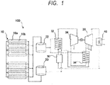
- FIG. 1 is a schematic illustration of the configuration of a solar thermal power generation system to be used for an embodiment of method of controlling a solar thermal power generation system according to the present invention.
- FIG. 1 is a schematic illustration of the configuration of a solar thermal power generation system to be used for an embodiment of method of controlling a solar thermal power generation system according to the present invention.
- the solar thermal power generation system of this embodiment is a so-called direct two-tank type solar thermal power generation system that employs molten salt commonly both as thermal storage medium and as heating medium.
- the solar thermal power generation system of this embodiment also adopts CSP generation.
- the heating section 10 for heating molten salt to condense sunlight in order to heat molten salt.
- the heating section 10 of this embodiment is of the parabolic trough type and includes gutter-shaped linearly extending condensers/reflectors 10a having a parabolic cross section and branches of conduit 10b each extending along or near the focal points of the parabolas (linearly extending through the focal points of the parabolic cross sections) of the corresponding one of the gutter-shaped condensers/reflectors 10a. Rays of sunlight reflected by the condensers/reflectors 10a are condensed at the continuous positions of the branches of the conduit 10b and transformed into heat, which heat in turn heats the molten salt flowing through the branches of the conduit 10b.
- the parabolic trough type heating section 10 has a simple structure and hence can be provided at relatively low cost and, at the same time, it does not require any sophisticated light condensing technique. In other words, the parabolic tough type heating section 10 can excellently operate with ease for condensation of sunlight. Because of these advantages, solar thermal power generation systems having a parabolic trough type heating section have a proven track record and are excellent in terms of reliability.
- the heating section 10 of this embodiment is by no means limited to the parabolic trough type and a heating section of any other type can be adopted for this embodiment so long as it can satisfactorily heat molten salt by means of thermal energy. Therefore, a heating section of any other known popular type such as the linear Fresnel type, the tower type or the dish type may be employed to replace the parabolic trough type heating section for the purpose of the present invention. Still alternatively, two or more than two of the above listed types may be employed in combination.
- the heating section 10 of this embodiment as shown in FIG. 1 includes a total of eight condensers collectors/reflectors 10a and a common conduit 10b that is branched to the eight thermal collectors/reflectors 10a.
- the parabolic trough type heating section is by no means limited to the above-described arrangement and may include an arbitrarily selected number of solar collectors/reflectors and/or the conduit of the heating section may have any arbitrarily selected piping arrangement.
- the heating section 10 heats molten salt to a temperature level higher than 400°C, which is the upper limit temperature when oil is conventionally employed as heating medium. While the temperature to which molten salt is heated in the heating section 10 of this embodiment is not subjected to any limitations so long as the temperature does not give rise to any thermal decomposition or the like of the molten salt of the heating section 10 that consequently results in an irreversible change to the molten salt and degrades the performance of the molten salt, although a higher temperature is preferable from the viewpoint of high-efficiency power generation. However, the heating temperature needs to be determined by taking the heat resistance of the entire system including the conduit 10b, the efficiency of power generation, the cost and other factors into consideration.
- the heating section 10 of this embodiment heats molten salt to not lower than 500°C, preferably not lower than 500° and not higher than 600°C, more preferably not lower than 540°C and not higher than 560°C.
- the conduit 10b connects a low-temperature thermal storage tank 20 and a high-temperature thermal storage tank 22 by way of the sunlight condensing sites of the heating section 10.
- the conduit 10b can flow the molten salt stored in the low-temperature thermal storage tank 20 and lead the flowing molten salt to the high-temperature thermal storage tank 22.
- nitrate-based molten salt For solar thermal power generation systems, the use of nitrate-based molten salt is advantageous from the viewpoint of safety, stability and cost and hence nitrate-based molten salt is being popularly employed.
- nitrate-based molten salt When nitrate-based molten salt is employed as heating medium, it can be heated to a temperature level higher than the temperature level that is obtained when oil is employed as conventional heating medium. Then, high-temperature steam can be obtained to realize high-efficiency solar thermal power generation.
- oil is employed as heating medium for solar thermal power generation and heated to a temperature level higher than 400°C for a long period of time, the oil can be decomposed to degrade its performance.
- nitrate-based molten salt is employed as heating medium and heated to a temperature level higher than 400°C for a long period of time, the molten salt is not decomposed at all and hence no degradation of its performance occurs.
- molten salt a mixture of sodium nitrate and potassium nitrate is employed as molten salt. It should be noted, however, the present invention is by no means limited to the use of such a mixture. In other words, any molten salt can be used for the purpose of the present invention so long as it is available both as thermal storage medium and heating medium for solar thermal power generation systems.
- nitrate-based molten salt not only the two-component mixture of sodium nitrate and potassium nitrate but also any of three-component mixture of sodium nitrate, potassium nitrate and lithium nitrate or the like and four-component mixture are known to date and any of these mixtures may selectively be employed for the purpose of the present invention.
- the two-component mixture of sodium nitrate and potassium nitrate shows a melting point of about 230°C and the heating system is so controlled as to heat the molten salt mixture to a temperature level higher than the melting point by 40 to 50°C in the actual operation environment in order to prevent the molten salt from being solidified.
- the melting point of the molten salt mixture is preferably low from the viewpoint of reducing the level of thermal energy consumption for the purpose of prevention of solidification particularly during the night in winter.
- molten salt needs to be selected by taking the safety, the stability, the viscosity at the operating temperature, the cost and other relevant factors into consideration.
- the solar thermal power generation system 100 of this embodiment comprises a low-temperature thermal storage tank 20 and a high-temperature thermal storage tank 22. More specifically, the solar thermal power generation system 100 of this embodiment comprises a two-tank type thermal storage section and low-temperature molten salt and high-temperature molten salt are separated and stored respectively in the low-temperature thermal storage tank and the high-temperature thermal storage tank.
- the thermal storage section of the present invention is by no means limited to the two-tank type and any other arrangement can alternatively be employed for the purpose of the present invention so long as it can separately and independently supply low-temperature molten salt and high-temperature molten salt.
- single tank type thermal storage sections are known in addition to two-tank type thermal storage sections.
- high-temperature molten salt is stored in an upper part of a single tank, while low-temperature molten salt is stored in a lower part of the single tank. Then, high-temperature molten salt and low-temperature molten salt can separately and independently be supplied from the single tank.
- molten salt is stored in the low-temperature thermal storage tank 20 when its temperature is low.
- the molten salt stored in the low-temperature thermal storage tank 20 receives solar energy from the condensers/reflectors 10a to become hot as it is put in the branches of the conduit 10b. Then, as the molten salt is heated to become hot, all the heated high-temperature molten salt is then stored in the high-temperature thermal storage tank 22 in this embodiment.
- Both the low-temperature thermal storage tank 20 and the high-temperature thermal storage tank 22 are not subjected to any particular limitations so long as they can store molten salt.
- the low-temperature thermal storage tank 20 and the high-temperature thermal storage tank 22 of this embodiment can store molten salt whose temperature will be shifted from a low-temperature level of about 270°C to a high-temperature level of about not lower than 500°C and vice versa and have a thermal insulation property, a thermal resistance property and durability. Additionally, it is particularly preferable that both the low-temperature thermal storage tank 20 and the high-temperature thermal storage tank 22 have high-mechanical strength and will not be damaged if the molten salt they contain is unexpectedly solidified.
- the superheater 32 generates superheated steam by way of heat exchange between heating medium (molten salt) and steam and supplies the superheated steam to the high-pressure turbine 36, which will be described in detail hereinafter.
- heating medium molten salt
- High-temperature molten salt is supplied to the superheater 32 from the high-temperature thermal storage tank 22.
- this embodiment is so designed that high-temperature molten salt is supplied to the superheater 32 from the high-temperature thermal storage tank 22.
- steam (water vapor) generated in the steam generator 30 is also supplied to the superheater 32.
- the supplied steam is heated by way of heat exchange between hot-temperature molten salt and the steam to become superheated steam.
- the molten salt that has discharged heat as a result of the heat exchange is fed to the steam generator 30.
- the steam generator 30 heats the water supplied from the condenser 40, which will be described in detail hereinafter, to generate steam. Then, it supplies the steam it generates to the superheater 32.
- the water supplied from the condenser 40 is heated to become steam by way of heat exchange between the molten salt discharged from the superheater 32 and the molten salt discharged from the reheater 34, which will be described in detail hereinafter.
- the molten salt that is cooled to become low-temperature molten salt as a result of discharging heat in the heat exchange is fed to the low-temperature thermal storage tank 20.
- the high-pressure turbine 36 is driven to operate by the superheated steam supplied from the superheater 32. More specifically, the turbine blades that the high-pressure turbine 36 has are driven to turn by the work of the superheated steam and the generator G generates electric power.
- the superheated steam that has done its work is discharged to the reheater 34, which will be described in detail hereinafter, as intermediary exhaust steam.
- the steam in the high-pressure turbine 36 of this embodiment is partly extracted and discharged to a preheater (not shown).
- the power generation efficiency of this embodiment can be raised as the heat of the extracted steam is utilized by the preheater.
- the reheater 34 produces reheated steam by way of heat exchange between heating medium (molten salt) and intermediary exhaust steam and supplies the produced reheated steam to the low-pressure turbine 38, which will be described in detail hereinafter.
- High-temperature molten salt is supplied to the reheater 34 from the high-temperature thermal storage tank 22.
- this embodiment is so designed that high-temperature molten salt is supplied to the reheater 34 from the high-temperature thermal storage tank 22.
- the intermediary exhaust steam discharged from the high-pressure turbine 36 is supplied to the reheater 34.
- the intermediary exhaust steam supplied from the high-pressure turbine 36 is heated by heat exchange between itself and high-temperature molten salt to become reheated steam.
- the molten steam that has discharged heat as a result of the heat exchange is then fed to the steam generator 30.
- the molten salt supplied from the high-temperature thermal storage tank 22 is divided into two parts, one of which is then supplied to the superheater 32 while the other is supplied to the reheater 34.
- the low-pressure turbine 38 is driven to operate by the reheated steam supplied from the reheater 34. More specifically, the turbine blades of the low-pressure turbine 38 are driven to turn by the work of the reheated steam and the generator G generates electric power.
- the reheated steam that has done its work is discharged to the condenser 40, which will be described in detail hereinafter, as exhaust steam.
- part of the steam is extracted stepwise (in four steps) and discharged typically to a heat exchanger (not shown) or the like.
- the power generation efficiency of this embodiment can be improved as the heat of the extracted steam is utilized by the heat exchanger or the like.
- the condenser 40 is provided to cool and condense the exhaust steam discharged from the low-pressure turbine 38 into water, thereby reducing the back pressure and raising the output.
- the obtained water is supplied to the steam generator 30 to serve for power generation once again.
- the above-described water and steam including superheated steam, reheated steam and so on are forced to circulate in the solar thermal power generation system by circulation means (not shown) including pumps that are appropriately arranged on the water/steam circulation path.
- the molten salt is forced to circulate in the solar thermal power generation system by circulation means (not shown) including pumps that are appropriately arranged on the molten salt circulation path.
- the reheated steam temperature detector (not shown) detects the temperature of the reheated steam that is discharged from the reheater 34 and supplied to the low-pressure turbine 38. Therefore, the reheated steam temperature detector is arranged on the steam flow path between the outlet of the reheater 34 and the inlet of the low-pressure turbine 38.
- the reheated steam temperature detector may be arranged at any position on the steam flow path between the outlet of the reheater 34 and the inlet of the low-pressure turbine 38 so long as the position is good for accurately detecting the reheated steam temperature.
- a plurality of reheated steam temperature detectors are arranged near the inlet of the low-pressure turbine 38 and each of them detects the reheated steam temperature.
- the reheated steam temperature detector is not subjected to any particular limitations so long as it can detect the reheated steam temperature. In other words, any temperature detecting mechanism may be adopted for the reheated steam temperature detector.
- the reheated steam temperature detector of this embodiment is so arranged as to constantly (continuously) detect the reheated steam temperature so that any abnormal situation that may arise to the solar thermal power generation system 100 can immediately be detected.
- the present invention is by no means limited to such an arrangement and it may alternatively be so arranged that the reheated steam temperature is detected only during the low charge operation of the solar thermal power generation system.
- the reheated steam temperature detected by the reheated steam temperature detector is sent to the reheater molten salt quantity control section, which is the section for controlling the quantity of molten salt to be supplied to the reheater in a low load operation as will be described in detail hereinafter.
- the solar thermal power generation system is designed to normally run under 100% load relative to the rated load.
- the load is reduced so that the solar thermal power generation system runs under low load.
- Such instances include those where the amount of solar radiation does not meet the requirement level and high-temperature molten salt is in short supply and those where the demand for electric power is small and the solar thermal power generation system is not allowed to satisfactorily transmit electric power to the outside.
- the load is reduced to make the solar thermal power generation system run under low load in order to suppress the consumption of high-temperature molten salt and prevent solidification of the molten salt until solar irradiation rises high.
- the solar thermal power generation system When the solar thermal power generation system is not allowed to satisfactorily transmit electric power to the outside particularly in early morning and late at night because the power consumption rate is low, the solar thermal power generation system cannot run for a normal operation and hence is forced to run under low load until the power consumption rate rises.
- solar thermal power generation systems are designed to run for normal operations and low load operations in a switched manner.
- the solar thermal power generation system 100 can achieve the highest power generation efficiency and operate well for power generation without causing the temperature of the exhaust steam coming out from the low-pressure turbine 38 to rise to an undesirably high level when it is made to run under the rated load (or 100% load).
- the solar thermal power generation system 100 is designed to circulate molten salt that can become very hot as heating medium, the temperature of the exhaust steam coming out from the low-pressure turbine 38 rises so that problems such as damages to the turbine blades can arise when the solar thermal power generation system 100 is made to run under low load.
- this embodiment is so designed that, when it is forced to run under a low load condition where the load is not greater than a predetermined ratio of the rated load, the quantity Mr of molten salt to be supplied to the reheater 34 is controlled by means of a reheater molten salt quantity control process, (reheater molten salt quantity control section) so as to prevent the temperature of the exhaust steam coming out from the low-pressure turbine 38 from excessively rising on a low load operation status where the solar thermal power generation system 100 is made to run with a load not greater than a predetermined ratio of the rated load.
- reheater molten salt quantity control process reheater molten salt quantity control section
- a low load operation status refers to an operation status where the load of the solar thermal power generation system 100 is not greater than 25% of the rated load. Note, however, when the load is too low, the operation of the solar thermal power generation system 100 can get into trouble. Therefore, even in an instance where the solar thermal power generation system 100 is required to be operated under low load, the system 100 has to run with a load not lower than the allowable minimum load.
- the expression of the allowable minimum load as used herein refers to the lowest necessary load for the operation of the solar thermal power generation system.
- This embodiment is made to run for a low load operation with a load that is preferably not less than 5% and not more than 25%, more preferably not less than 5% and not more than 20%, most preferably not less than 7% and not more than 15%.
- any solar thermal power generation system is most preferably made to run on a low load operation status with a load that is equal to the predetermined ratio of the rated load of the solar thermal power generation system that is specific to the system.
- the reheater molten salt quantity control section obtains the reheated steam temperature output from the reheated steam temperature detector in a low load operation and controls the quantity Mr of molten salt to be supplied to the reheater 34 so as to make the reheated steam temperature not higher than 430°C.
- the reheater molten salt quantity control section of this embodiment reduces the quantity Mr of molten salt to be supplied to the reheater 34 so as to make the reheated steam temperature not higher than 450°C.
- the reheated steam temperature is not lower than 370°C and not higher than 430°C.
- the temperature of the reheated steam to be supplied to the low-pressure turbine 38 falls so as to be not higher than 450°C during the low load operation, the inside of the low-pressure turbine 38 never becomes excessively hot and hence the turbine blades of the low-pressure turbine 38 are prevented from being damaged. Additionally, since the temperature of the molten salt to be supplied to the superheater 32 and the reheater 34 does not fall, the temperature of the superheated steam is held to be not lower than 500°C so that the power generation efficiency of the solar thermal power generation system 100 is prevented from falling and hence the system 100 can operate for high-efficiency power generation.
- the power generation efficiency of the low-pressure turbine 38 undesirably falls if the reheated steam temperature is unnecessarily lowered.
- the temperature of the exhaust steam discharged from the low-pressure turbine 38 needs to be lowered in order to satisfactorily reduce the risk of damaging the turbine blades of the low-pressure turbine 38. Therefore, it is particularly desirable to maintain the temperature of the reheated steam to a high level from the viewpoint of achieving high-power generation efficiency, although the temperature of the reheated steam needs to be not higher than 450°C.
- the reheater molten salt quantity control section may be so arranged as to control the quantity Mr of molten salt to be supplied to the reheater 34 by obtaining not only the temperature of the reheated steam output from the reheated steam temperature detector but also one or more than one other temperatures.
- the quantity Mr of molten salt to be supplied to the reheater 34 may be controlled by acquiring the temperature output from a temperature detector that can detect the temperature of the steam discharged from the outlet of the low-pressure turbine 38 and using it as control factor for controlling the quantity Mr of molten salt to be supplied to the reheater 34 along with the temperature of the reheated steam output from the reheated steam temperature detector.
- the amount of steam to be used per unit time by the solar thermal power generation system 100 is determined on the basis of its electric power generation capacity. As the amount of steam to be used per unit time is determined, the required amount of high-temperature molten salt, which is the total amount Mt of molten salt to be supplied to both the superheater 32 and the reheater 34, is determined.
- the quantity Mr of molten salt to be supplied to the reheater 34 during a low load operation is determined by the reheater molten salt quantity control section.
- the difference (Mt - Mr) between the total amount Mt of molten salt to be supplied to both the superheater 32 and the reheater 34 and the quantity Mr of molten salt to be supplied to the reheater 32 is equal to the quantity Ms of molten salt to be supplied to the superheater 32. In this way, it is possible to determine and control the quantity of molten salt to be supplied (circulated) for the entire solar thermal power generation system 100 for a low load operation.
- the quantity Mr of molten salt to be supplied to the reheater 34 for a normal operation can theoretically be determined. In other words, it is not necessary to control the quantity Mr of molten salt to be supplied to the reheater 34 by means of the reheater molten salt quantity control section for the normal operation.
- any of the conventional arrangements that are provided for solar thermal power generation system may also be provided for a solar thermal power generation system according to the present invention.
- the solar thermal power generation of the solar thermal power generation system as shown in FIG. 1 was computer simulated in each of Example 1, Comparative Examples 1 ⁇ 2 and Reference Example 1.
- Comparative Example 1 a low load operation where the solar thermal power generation system 100 was operated with 10% load of the rated load was computer simulated.
- the temperature (of the superheated steam) at the inlet of the high-pressure turbine and the temperature (of the reheated steam) at the inlet of the low-pressure turbine were lowered under control by lowering the temperature of molten salt itself.
- Comparative Example 1 the steam temperature at the outlet of the low-pressure turbine 38 was 53.83°C. Additionally, the electric power generation efficiency of Comparative Example 1 was employed as reference value to evaluate the electric power generation efficiency of Comparative Example 2 and that of Example 1 as will be described in greater detail hereinafer.
- Comparative Example 2 a low load operation where the solar thermal power generation system 100 was operated with 10% load of the rated load was computer simulated. However, in Comparative Example 2, the temperature of molten salt was not lowered unlike in Comparative Example 1 but the quantity Mr of molten salt to be supplied to the reheater 34 was controlled in the conventional manner of using the target steam flow rate as index.
- Comparative Example 2 While the electric power generation efficiency was raised by about 2.95% when compared with the electric power generation efficiency of Comparative Example 1, the steam temperature at the outlet of the low-pressure turbine 38 was 126.80°C, which was far higher than the temperature that the low-pressure turbine 38 can endure in actual operations.
- Example 1 the quantity Mr of molten salt to be supplied to the reheater 34 was controlled by following the above-described reheater molten salt quantity control process of using the temperature of the reheated steam as index. More specifically, the quantity Mr of molten salt to be supplied to the reheater 34 was so controlled as to make the reheated steam temperature at the inlet of the low-pressure turbine 38 to be equal to 400°C.
- Example 1 the steam temperature at the outlet of the low-pressure turbine 38 was 53.83°C. Since the steam temperature at the outlet of the low-pressure turbine 38 was reasonably low as pointed out above, there was no risk of damaging the turbine blades even if the low-pressure turbine 38 was operated for a long period of time. Additionally, the electric power generation efficiency of Example 1 was higher by about 0.91% than the electric power generation efficiency of Comparative Example 1. Thus, high-electric power generation efficiency could be achieved with Example 1.
- the solar thermal power generation system 100 was operated with the rated load (100% load). In other words, the solar thermal power generation system 100 was on a normal operation status in Reference Example 1.
- any undesirable rise of the temperature of the exhaust steam discharged from the low-pressure turbine can be prevented from taking place by controlling the quantity of molten salt to be supplied to the reheater, using the reheated steam temperature as index in the low load operation. Additionally, any undesirable fall of the temperature of the superheated steam to be supplied to the high-pressure turbine can also be prevented from taking place.
- the durability of the solar thermal power generation system can be improved without raising the cost of installing the system, while suppressing any undesirable rise of the temperature of exhaust steam so that high-efficiency power generation can be achieved.
Landscapes
- Engineering & Computer Science (AREA)
- Mechanical Engineering (AREA)
- General Engineering & Computer Science (AREA)
- Chemical & Material Sciences (AREA)
- Combustion & Propulsion (AREA)
- Life Sciences & Earth Sciences (AREA)
- Sustainable Energy (AREA)
- Sustainable Development (AREA)
- Physics & Mathematics (AREA)
- Thermal Sciences (AREA)
- Engine Equipment That Uses Special Cycles (AREA)
- Control Of Turbines (AREA)
Applications Claiming Priority (2)
| Application Number | Priority Date | Filing Date | Title |
|---|---|---|---|
| JP2015211799A JP6596303B2 (ja) | 2015-10-28 | 2015-10-28 | 太陽熱発電装置およびその制御方法 |
| PCT/JP2016/004668 WO2017073040A1 (ja) | 2015-10-28 | 2016-10-24 | 太陽熱発電装置およびその制御方法 |
Publications (3)
| Publication Number | Publication Date |
|---|---|
| EP3369926A1 EP3369926A1 (en) | 2018-09-05 |
| EP3369926A4 EP3369926A4 (en) | 2019-06-19 |
| EP3369926B1 true EP3369926B1 (en) | 2021-03-03 |
Family
ID=58630154
Family Applications (1)
| Application Number | Title | Priority Date | Filing Date |
|---|---|---|---|
| EP16859278.0A Active EP3369926B1 (en) | 2015-10-28 | 2016-10-24 | Solar thermal power generation system and method for controlling same |
Country Status (9)
| Country | Link |
|---|---|
| EP (1) | EP3369926B1 (ja) |
| JP (1) | JP6596303B2 (ja) |
| CN (1) | CN108291532B (ja) |
| CL (1) | CL2018001011A1 (ja) |
| ES (1) | ES2861437T3 (ja) |
| MA (1) | MA43127B1 (ja) |
| PT (1) | PT3369926T (ja) |
| SA (1) | SA518391449B1 (ja) |
| WO (1) | WO2017073040A1 (ja) |
Families Citing this family (13)
| Publication number | Priority date | Publication date | Assignee | Title |
|---|---|---|---|---|
| AR111473A1 (es) | 2017-04-19 | 2019-07-17 | Sumitomo Chemical Co | Método para la preparación de compuesto de piridina |
| CN107191343B (zh) * | 2017-07-28 | 2023-02-07 | 中国电力工程顾问集团西北电力设计院有限公司 | 一种全负荷熔盐蒸汽发生系统及其控制方法 |
| CN109838770A (zh) * | 2017-09-11 | 2019-06-04 | 甘肃光热发电有限公司 | 光热发电蒸汽发生系统 |
| CN107905862A (zh) * | 2017-11-24 | 2018-04-13 | 兰州理工大学 | 太阳能蝶式涡旋昼夜发电系统 |
| CN110886629A (zh) * | 2018-09-07 | 2020-03-17 | 上海明华电力技术工程有限公司 | 一种利用光热实现热电解耦的系统和方法 |
| CN109083811A (zh) * | 2018-09-25 | 2018-12-25 | 兰州大成聚光能源科技有限公司 | 风力光热发电设备和方法 |
| CN109026224A (zh) * | 2018-10-17 | 2018-12-18 | 中国船舶重工集团公司第七0三研究所 | 一种单罐蓄热式储能热电联供系统 |
| KR102180173B1 (ko) * | 2018-11-28 | 2020-11-19 | 선다코리아주식회사 | 산업공정용 태양열 시스템 |
| WO2020145106A1 (ja) * | 2019-01-07 | 2020-07-16 | 株式会社Ihi | 蒸気供給装置及び乾燥システム |
| CN110006026B (zh) * | 2019-04-18 | 2023-10-17 | 北京工业大学 | 一种火电厂深度调峰系统 |
| CN110206603B (zh) * | 2019-05-16 | 2023-08-15 | 浙江浙能技术研究院有限公司 | 一种基于蒸汽加热熔盐蓄热的火电机组热电解耦系统及方法 |
| CN112781271A (zh) * | 2021-02-03 | 2021-05-11 | 国电龙源电力技术工程有限责任公司 | 蓄热型太阳能联合供冷供热系统 |
| CN114251642A (zh) * | 2021-11-30 | 2022-03-29 | 碳中和绿色建筑科技(苏州)有限公司 | 熔盐储热换热系统 |
Family Cites Families (14)
| Publication number | Priority date | Publication date | Assignee | Title |
|---|---|---|---|---|
| JPS5669408A (en) * | 1979-11-12 | 1981-06-10 | Hitachi Ltd | Reheat turbine plant |
| JPS62121807A (ja) * | 1985-11-21 | 1987-06-03 | Toshiba Corp | タ−ビン制御装置 |
| AU2011238122B2 (en) * | 2010-03-30 | 2015-02-26 | Siemens Aktiengesellschaft | Solar thermal power plant using indirect evaporation and method for operating such a solar thermal power plant |
| BR112013007036B1 (pt) * | 2010-09-30 | 2022-04-19 | Dow Global Technologies Llc | Aparelho para produzir vapor superaquecido de uma planta de energia solar de concentração e processo para produzir vapor superaquecido de uma planta de energia solar de concentração |
| DE102010041903B4 (de) * | 2010-10-04 | 2017-03-09 | Siemens Aktiengesellschaft | Durchlaufdampferzeuger mit integriertem Zwischenüberhitzer |
| WO2013018014A2 (en) * | 2011-08-02 | 2013-02-07 | Brightsource Industries (Israel) Ltd. | Solar energy thermal storage systems, devices, and methods |
| US9816491B2 (en) * | 2011-09-29 | 2017-11-14 | Solarreserve Technology, Llc | Solar power system and method therefor |
| DE102011054618B4 (de) * | 2011-10-19 | 2020-10-22 | Deutsches Zentrum für Luft- und Raumfahrt e.V. | Verfahren zum Betreiben eines solarthermischen Kraftwerks und solarthermisches Kraftwerk |
| US20130111902A1 (en) * | 2011-11-03 | 2013-05-09 | Mansour Maleki-Ardebili | Solar power system and method of operating a solar power system |
| DE102012102115A1 (de) * | 2012-02-16 | 2013-08-22 | Deutsches Zentrum für Luft- und Raumfahrt e.V. | Solarthermisches Kraftwerk und Verfahren zum Betreiben eines solarthermischen Kraftwerks |
| EP2781832A1 (de) * | 2013-03-18 | 2014-09-24 | Siemens Aktiengesellschaft | Verfahren zum Anfahren eines solarthermischen Kraftwerks |
| US20150128594A1 (en) * | 2013-11-11 | 2015-05-14 | Esolar Inc. | Heat Transfer Fluid Flow Rate and Temperature Regulation System |
| CN204239166U (zh) * | 2014-10-11 | 2015-04-01 | 云南能投能源产业发展研究院 | 太阳能热力发电装置 |
| CN204186541U (zh) * | 2014-11-06 | 2015-03-04 | 中国电力工程顾问集团华北电力设计院工程有限公司 | 熔融盐储热太阳能热发电系统 |
-
2015
- 2015-10-28 JP JP2015211799A patent/JP6596303B2/ja not_active Expired - Fee Related
-
2016
- 2016-10-24 WO PCT/JP2016/004668 patent/WO2017073040A1/ja active Application Filing
- 2016-10-24 CN CN201680064898.6A patent/CN108291532B/zh not_active Expired - Fee Related
- 2016-10-24 PT PT168592780T patent/PT3369926T/pt unknown
- 2016-10-24 ES ES16859278T patent/ES2861437T3/es active Active
- 2016-10-24 MA MA43127A patent/MA43127B1/fr unknown
- 2016-10-24 EP EP16859278.0A patent/EP3369926B1/en active Active
-
2018
- 2018-04-19 CL CL2018001011A patent/CL2018001011A1/es unknown
- 2018-04-26 SA SA518391449A patent/SA518391449B1/ar unknown
Non-Patent Citations (1)
| Title |
|---|
| None * |
Also Published As
| Publication number | Publication date |
|---|---|
| EP3369926A4 (en) | 2019-06-19 |
| JP2017082678A (ja) | 2017-05-18 |
| JP6596303B2 (ja) | 2019-10-23 |
| CN108291532B (zh) | 2020-03-06 |
| EP3369926A1 (en) | 2018-09-05 |
| SA518391449B1 (ar) | 2021-06-11 |
| WO2017073040A1 (ja) | 2017-05-04 |
| MA43127A (fr) | 2018-09-05 |
| PT3369926T (pt) | 2021-04-06 |
| ES2861437T3 (es) | 2021-10-06 |
| CN108291532A (zh) | 2018-07-17 |
| CL2018001011A1 (es) | 2018-09-28 |
| MA43127B1 (fr) | 2021-02-26 |
Similar Documents
| Publication | Publication Date | Title |
|---|---|---|
| EP3369926B1 (en) | Solar thermal power generation system and method for controlling same | |
| US9816491B2 (en) | Solar power system and method therefor | |
| US10072530B2 (en) | Hybrid power generation system using solar energy and bioenergy | |
| EP3112679B1 (en) | Solar thermal power generation system and solar thermal power generation method | |
| EP2722496B1 (en) | Power Plant comprising a thermal storage unit | |
| US9683788B2 (en) | Steam heat storage system | |
| US20120102950A1 (en) | Solar thermal power plant with the integration of an aeroderivative turbine | |
| US20140223906A1 (en) | Solar/gas hybrid power system configurations and methods of use | |
| EP2647841B1 (en) | Solar thermal power system | |
| EP2885590A1 (en) | Plant for energy production | |
| Schenk et al. | Transient simulation of the power block in a parabolic trough power plant | |
| CN111677640A (zh) | 解耦集热储热与放热发电的槽式光热发电系统及运行方法 | |
| EP3907390A1 (en) | Power generation plant | |
| Way | Storing the sun: molten salt provides highly efficient thermal storage | |
| WO2014123537A1 (en) | Solar/gas hybrid power system configurations and methods of use | |
| EP2757259B1 (en) | Solar Thermal Power System | |
| AU2016253382A1 (en) | Molten salt once-through steam generator | |
| US10006310B2 (en) | Steam power plant with an additional flexible solar system for the flexible integration of solar energy | |
| CN216554042U (zh) | 一种基于熔盐储热的储热耦合火电机组系统 | |
| US20140265597A1 (en) | Distributed Energy System Architecture with Thermal Storage | |
| Belverato et al. | Part-Load of Steam Rankine Cycles for Solar Salts-Based Concentrating Solar Power Plants | |
| Shapiro et al. | Improving the maneuverability of combined-cycle power plants through the use of hydrogen-oxygen steam generators | |
| CN213144666U (zh) | 一种解耦集热储热与放热发电的槽式光热发电系统 | |
| Vogel et al. | High temperatures in line focusing systems: Dual loop cycle efficiency and heat losses | |
| Muto et al. | Partial load characteristics of the supercritical CO2 gas turbine system for the solar thermal power system with the na-al-CO2 heat exchanger |
Legal Events
| Date | Code | Title | Description |
|---|---|---|---|
| STAA | Information on the status of an ep patent application or granted ep patent |
Free format text: STATUS: THE INTERNATIONAL PUBLICATION HAS BEEN MADE |
|
| PUAI | Public reference made under article 153(3) epc to a published international application that has entered the european phase |
Free format text: ORIGINAL CODE: 0009012 |
|
| STAA | Information on the status of an ep patent application or granted ep patent |
Free format text: STATUS: REQUEST FOR EXAMINATION WAS MADE |
|
| 17P | Request for examination filed |
Effective date: 20180426 |
|
| AK | Designated contracting states |
Kind code of ref document: A1 Designated state(s): AL AT BE BG CH CY CZ DE DK EE ES FI FR GB GR HR HU IE IS IT LI LT LU LV MC MK MT NL NO PL PT RO RS SE SI SK SM TR |
|
| AX | Request for extension of the european patent |
Extension state: BA ME |
|
| DAX | Request for extension of the european patent (deleted) | ||
| RAV | Requested validation state of the european patent: fee paid |
Extension state: MA Effective date: 20180426 |
|
| RIC1 | Information provided on ipc code assigned before grant |
Ipc: F24J 2/42 20060101ALI20170517BHEP Ipc: F01K 27/02 20060101ALI20170517BHEP Ipc: F03G 6/00 20060101AFI20170517BHEP Ipc: F01K 7/22 20060101ALI20170517BHEP Ipc: F22G 5/12 20060101ALI20170517BHEP |
|
| A4 | Supplementary search report drawn up and despatched |
Effective date: 20190516 |
|
| RIC1 | Information provided on ipc code assigned before grant |
Ipc: F22G 5/12 20060101ALI20190510BHEP Ipc: F22G 5/00 20060101ALI20190510BHEP Ipc: F22B 1/00 20060101ALI20190510BHEP Ipc: F01K 27/02 20060101ALI20190510BHEP Ipc: F03G 6/00 20060101AFI20190510BHEP Ipc: F01K 13/02 20060101ALI20190510BHEP Ipc: F01K 7/22 20060101ALI20190510BHEP |
|
| GRAP | Despatch of communication of intention to grant a patent |
Free format text: ORIGINAL CODE: EPIDOSNIGR1 |
|
| STAA | Information on the status of an ep patent application or granted ep patent |
Free format text: STATUS: GRANT OF PATENT IS INTENDED |
|
| INTG | Intention to grant announced |
Effective date: 20200929 |
|
| GRAS | Grant fee paid |
Free format text: ORIGINAL CODE: EPIDOSNIGR3 |
|
| STAA | Information on the status of an ep patent application or granted ep patent |
Free format text: STATUS: GRANT OF PATENT IS INTENDED |
|
| GRAA | (expected) grant |
Free format text: ORIGINAL CODE: 0009210 |
|
| STAA | Information on the status of an ep patent application or granted ep patent |
Free format text: STATUS: THE PATENT HAS BEEN GRANTED |
|
| REG | Reference to a national code |
Ref country code: MA Ref legal event code: VAGR Ref document number: 43127 Country of ref document: MA Kind code of ref document: B1 |
|
| AK | Designated contracting states |
Kind code of ref document: B1 Designated state(s): AL AT BE BG CH CY CZ DE DK EE ES FI FR GB GR HR HU IE IS IT LI LT LU LV MC MK MT NL NO PL PT RO RS SE SI SK SM TR |
|
| REG | Reference to a national code |
Ref country code: GB Ref legal event code: FG4D |
|
| REG | Reference to a national code |
Ref country code: AT Ref legal event code: REF Ref document number: 1367479 Country of ref document: AT Kind code of ref document: T Effective date: 20210315 Ref country code: CH Ref legal event code: EP |
|
| REG | Reference to a national code |
Ref country code: DE Ref legal event code: R096 Ref document number: 602016053771 Country of ref document: DE |
|
| REG | Reference to a national code |
Ref country code: IE Ref legal event code: FG4D |
|
| REG | Reference to a national code |
Ref country code: PT Ref legal event code: SC4A Ref document number: 3369926 Country of ref document: PT Date of ref document: 20210406 Kind code of ref document: T Free format text: AVAILABILITY OF NATIONAL TRANSLATION Effective date: 20210330 |
|
| REG | Reference to a national code |
Ref country code: LT Ref legal event code: MG9D |
|
| PG25 | Lapsed in a contracting state [announced via postgrant information from national office to epo] |
Ref country code: LT Free format text: LAPSE BECAUSE OF FAILURE TO SUBMIT A TRANSLATION OF THE DESCRIPTION OR TO PAY THE FEE WITHIN THE PRESCRIBED TIME-LIMIT Effective date: 20210303 Ref country code: BG Free format text: LAPSE BECAUSE OF FAILURE TO SUBMIT A TRANSLATION OF THE DESCRIPTION OR TO PAY THE FEE WITHIN THE PRESCRIBED TIME-LIMIT Effective date: 20210603 Ref country code: NO Free format text: LAPSE BECAUSE OF FAILURE TO SUBMIT A TRANSLATION OF THE DESCRIPTION OR TO PAY THE FEE WITHIN THE PRESCRIBED TIME-LIMIT Effective date: 20210603 Ref country code: FI Free format text: LAPSE BECAUSE OF FAILURE TO SUBMIT A TRANSLATION OF THE DESCRIPTION OR TO PAY THE FEE WITHIN THE PRESCRIBED TIME-LIMIT Effective date: 20210303 Ref country code: GR Free format text: LAPSE BECAUSE OF FAILURE TO SUBMIT A TRANSLATION OF THE DESCRIPTION OR TO PAY THE FEE WITHIN THE PRESCRIBED TIME-LIMIT Effective date: 20210604 Ref country code: HR Free format text: LAPSE BECAUSE OF FAILURE TO SUBMIT A TRANSLATION OF THE DESCRIPTION OR TO PAY THE FEE WITHIN THE PRESCRIBED TIME-LIMIT Effective date: 20210303 |
|
| REG | Reference to a national code |
Ref country code: NL Ref legal event code: MP Effective date: 20210303 |
|
| REG | Reference to a national code |
Ref country code: AT Ref legal event code: MK05 Ref document number: 1367479 Country of ref document: AT Kind code of ref document: T Effective date: 20210303 |
|
| PG25 | Lapsed in a contracting state [announced via postgrant information from national office to epo] |
Ref country code: SE Free format text: LAPSE BECAUSE OF FAILURE TO SUBMIT A TRANSLATION OF THE DESCRIPTION OR TO PAY THE FEE WITHIN THE PRESCRIBED TIME-LIMIT Effective date: 20210303 Ref country code: PL Free format text: LAPSE BECAUSE OF FAILURE TO SUBMIT A TRANSLATION OF THE DESCRIPTION OR TO PAY THE FEE WITHIN THE PRESCRIBED TIME-LIMIT Effective date: 20210303 Ref country code: RS Free format text: LAPSE BECAUSE OF FAILURE TO SUBMIT A TRANSLATION OF THE DESCRIPTION OR TO PAY THE FEE WITHIN THE PRESCRIBED TIME-LIMIT Effective date: 20210303 Ref country code: LV Free format text: LAPSE BECAUSE OF FAILURE TO SUBMIT A TRANSLATION OF THE DESCRIPTION OR TO PAY THE FEE WITHIN THE PRESCRIBED TIME-LIMIT Effective date: 20210303 |
|
| PG25 | Lapsed in a contracting state [announced via postgrant information from national office to epo] |
Ref country code: NL Free format text: LAPSE BECAUSE OF FAILURE TO SUBMIT A TRANSLATION OF THE DESCRIPTION OR TO PAY THE FEE WITHIN THE PRESCRIBED TIME-LIMIT Effective date: 20210303 |
|
| REG | Reference to a national code |
Ref country code: ES Ref legal event code: FG2A Ref document number: 2861437 Country of ref document: ES Kind code of ref document: T3 Effective date: 20211006 |
|
| PG25 | Lapsed in a contracting state [announced via postgrant information from national office to epo] |
Ref country code: SM Free format text: LAPSE BECAUSE OF FAILURE TO SUBMIT A TRANSLATION OF THE DESCRIPTION OR TO PAY THE FEE WITHIN THE PRESCRIBED TIME-LIMIT Effective date: 20210303 Ref country code: AT Free format text: LAPSE BECAUSE OF FAILURE TO SUBMIT A TRANSLATION OF THE DESCRIPTION OR TO PAY THE FEE WITHIN THE PRESCRIBED TIME-LIMIT Effective date: 20210303 Ref country code: CZ Free format text: LAPSE BECAUSE OF FAILURE TO SUBMIT A TRANSLATION OF THE DESCRIPTION OR TO PAY THE FEE WITHIN THE PRESCRIBED TIME-LIMIT Effective date: 20210303 Ref country code: EE Free format text: LAPSE BECAUSE OF FAILURE TO SUBMIT A TRANSLATION OF THE DESCRIPTION OR TO PAY THE FEE WITHIN THE PRESCRIBED TIME-LIMIT Effective date: 20210303 |
|
| PGFP | Annual fee paid to national office [announced via postgrant information from national office to epo] |
Ref country code: IT Payment date: 20210910 Year of fee payment: 6 |
|
| PG25 | Lapsed in a contracting state [announced via postgrant information from national office to epo] |
Ref country code: SK Free format text: LAPSE BECAUSE OF FAILURE TO SUBMIT A TRANSLATION OF THE DESCRIPTION OR TO PAY THE FEE WITHIN THE PRESCRIBED TIME-LIMIT Effective date: 20210303 Ref country code: RO Free format text: LAPSE BECAUSE OF FAILURE TO SUBMIT A TRANSLATION OF THE DESCRIPTION OR TO PAY THE FEE WITHIN THE PRESCRIBED TIME-LIMIT Effective date: 20210303 Ref country code: IS Free format text: LAPSE BECAUSE OF FAILURE TO SUBMIT A TRANSLATION OF THE DESCRIPTION OR TO PAY THE FEE WITHIN THE PRESCRIBED TIME-LIMIT Effective date: 20210703 |
|
| REG | Reference to a national code |
Ref country code: DE Ref legal event code: R097 Ref document number: 602016053771 Country of ref document: DE |
|
| PLBE | No opposition filed within time limit |
Free format text: ORIGINAL CODE: 0009261 |
|
| STAA | Information on the status of an ep patent application or granted ep patent |
Free format text: STATUS: NO OPPOSITION FILED WITHIN TIME LIMIT |
|
| PG25 | Lapsed in a contracting state [announced via postgrant information from national office to epo] |
Ref country code: DK Free format text: LAPSE BECAUSE OF FAILURE TO SUBMIT A TRANSLATION OF THE DESCRIPTION OR TO PAY THE FEE WITHIN THE PRESCRIBED TIME-LIMIT Effective date: 20210303 Ref country code: AL Free format text: LAPSE BECAUSE OF FAILURE TO SUBMIT A TRANSLATION OF THE DESCRIPTION OR TO PAY THE FEE WITHIN THE PRESCRIBED TIME-LIMIT Effective date: 20210303 |
|
| PGFP | Annual fee paid to national office [announced via postgrant information from national office to epo] |
Ref country code: ES Payment date: 20211105 Year of fee payment: 6 Ref country code: PT Payment date: 20211025 Year of fee payment: 6 |
|
| 26N | No opposition filed |
Effective date: 20211206 |
|
| PG25 | Lapsed in a contracting state [announced via postgrant information from national office to epo] |
Ref country code: SI Free format text: LAPSE BECAUSE OF FAILURE TO SUBMIT A TRANSLATION OF THE DESCRIPTION OR TO PAY THE FEE WITHIN THE PRESCRIBED TIME-LIMIT Effective date: 20210303 |
|
| REG | Reference to a national code |
Ref country code: DE Ref legal event code: R119 Ref document number: 602016053771 Country of ref document: DE |
|
| REG | Reference to a national code |
Ref country code: CH Ref legal event code: PL |
|
| PG25 | Lapsed in a contracting state [announced via postgrant information from national office to epo] |
Ref country code: IS Free format text: LAPSE BECAUSE OF FAILURE TO SUBMIT A TRANSLATION OF THE DESCRIPTION OR TO PAY THE FEE WITHIN THE PRESCRIBED TIME-LIMIT Effective date: 20210703 |
|
| REG | Reference to a national code |
Ref country code: BE Ref legal event code: MM Effective date: 20211031 |
|
| GBPC | Gb: european patent ceased through non-payment of renewal fee |
Effective date: 20211024 |
|
| PG25 | Lapsed in a contracting state [announced via postgrant information from national office to epo] |
Ref country code: MC Free format text: LAPSE BECAUSE OF FAILURE TO SUBMIT A TRANSLATION OF THE DESCRIPTION OR TO PAY THE FEE WITHIN THE PRESCRIBED TIME-LIMIT Effective date: 20210303 |
|
| PG25 | Lapsed in a contracting state [announced via postgrant information from national office to epo] |
Ref country code: LU Free format text: LAPSE BECAUSE OF NON-PAYMENT OF DUE FEES Effective date: 20211024 Ref country code: GB Free format text: LAPSE BECAUSE OF NON-PAYMENT OF DUE FEES Effective date: 20211024 Ref country code: DE Free format text: LAPSE BECAUSE OF NON-PAYMENT OF DUE FEES Effective date: 20220503 Ref country code: BE Free format text: LAPSE BECAUSE OF NON-PAYMENT OF DUE FEES Effective date: 20211031 |
|
| PG25 | Lapsed in a contracting state [announced via postgrant information from national office to epo] |
Ref country code: LI Free format text: LAPSE BECAUSE OF NON-PAYMENT OF DUE FEES Effective date: 20211031 Ref country code: CH Free format text: LAPSE BECAUSE OF NON-PAYMENT OF DUE FEES Effective date: 20211031 |
|
| PG25 | Lapsed in a contracting state [announced via postgrant information from national office to epo] |
Ref country code: FR Free format text: LAPSE BECAUSE OF NON-PAYMENT OF DUE FEES Effective date: 20211031 |
|
| PG25 | Lapsed in a contracting state [announced via postgrant information from national office to epo] |
Ref country code: IE Free format text: LAPSE BECAUSE OF NON-PAYMENT OF DUE FEES Effective date: 20211024 |
|
| PG25 | Lapsed in a contracting state [announced via postgrant information from national office to epo] |
Ref country code: HU Free format text: LAPSE BECAUSE OF FAILURE TO SUBMIT A TRANSLATION OF THE DESCRIPTION OR TO PAY THE FEE WITHIN THE PRESCRIBED TIME-LIMIT; INVALID AB INITIO Effective date: 20161024 |
|
| PG25 | Lapsed in a contracting state [announced via postgrant information from national office to epo] |
Ref country code: CY Free format text: LAPSE BECAUSE OF FAILURE TO SUBMIT A TRANSLATION OF THE DESCRIPTION OR TO PAY THE FEE WITHIN THE PRESCRIBED TIME-LIMIT Effective date: 20210303 |
|
| PG25 | Lapsed in a contracting state [announced via postgrant information from national office to epo] |
Ref country code: PT Free format text: LAPSE BECAUSE OF NON-PAYMENT OF DUE FEES Effective date: 20230424 |
|
| PG25 | Lapsed in a contracting state [announced via postgrant information from national office to epo] |
Ref country code: IT Free format text: LAPSE BECAUSE OF NON-PAYMENT OF DUE FEES Effective date: 20221024 |
|
| REG | Reference to a national code |
Ref country code: ES Ref legal event code: FD2A Effective date: 20231129 |
|
| PG25 | Lapsed in a contracting state [announced via postgrant information from national office to epo] |
Ref country code: ES Free format text: LAPSE BECAUSE OF NON-PAYMENT OF DUE FEES Effective date: 20221025 |
|
| PG25 | Lapsed in a contracting state [announced via postgrant information from national office to epo] |
Ref country code: ES Free format text: LAPSE BECAUSE OF NON-PAYMENT OF DUE FEES Effective date: 20221025 |
|
| PG25 | Lapsed in a contracting state [announced via postgrant information from national office to epo] |
Ref country code: MK Free format text: LAPSE BECAUSE OF FAILURE TO SUBMIT A TRANSLATION OF THE DESCRIPTION OR TO PAY THE FEE WITHIN THE PRESCRIBED TIME-LIMIT Effective date: 20210303 |