EP3369858A1 - Clothes-drying machine - Google Patents
Clothes-drying machine Download PDFInfo
- Publication number
- EP3369858A1 EP3369858A1 EP16859073.5A EP16859073A EP3369858A1 EP 3369858 A1 EP3369858 A1 EP 3369858A1 EP 16859073 A EP16859073 A EP 16859073A EP 3369858 A1 EP3369858 A1 EP 3369858A1
- Authority
- EP
- European Patent Office
- Prior art keywords
- fan
- volute
- drying
- contour
- circular
- Prior art date
- Legal status (The legal status is an assumption and is not a legal conclusion. Google has not performed a legal analysis and makes no representation as to the accuracy of the status listed.)
- Granted
Links
Images



Classifications
-
- D—TEXTILES; PAPER
- D06—TREATMENT OF TEXTILES OR THE LIKE; LAUNDERING; FLEXIBLE MATERIALS NOT OTHERWISE PROVIDED FOR
- D06F—LAUNDERING, DRYING, IRONING, PRESSING OR FOLDING TEXTILE ARTICLES
- D06F58/00—Domestic laundry dryers
- D06F58/20—General details of domestic laundry dryers
-
- D—TEXTILES; PAPER
- D06—TREATMENT OF TEXTILES OR THE LIKE; LAUNDERING; FLEXIBLE MATERIALS NOT OTHERWISE PROVIDED FOR
- D06F—LAUNDERING, DRYING, IRONING, PRESSING OR FOLDING TEXTILE ARTICLES
- D06F58/00—Domestic laundry dryers
- D06F58/02—Domestic laundry dryers having dryer drums rotating about a horizontal axis
- D06F58/04—Details
-
- D—TEXTILES; PAPER
- D06—TREATMENT OF TEXTILES OR THE LIKE; LAUNDERING; FLEXIBLE MATERIALS NOT OTHERWISE PROVIDED FOR
- D06F—LAUNDERING, DRYING, IRONING, PRESSING OR FOLDING TEXTILE ARTICLES
- D06F2103/00—Parameters monitored or detected for the control of domestic laundry washing machines, washer-dryers or laundry dryers
- D06F2103/28—Air properties
- D06F2103/34—Humidity
-
- D—TEXTILES; PAPER
- D06—TREATMENT OF TEXTILES OR THE LIKE; LAUNDERING; FLEXIBLE MATERIALS NOT OTHERWISE PROVIDED FOR
- D06F—LAUNDERING, DRYING, IRONING, PRESSING OR FOLDING TEXTILE ARTICLES
- D06F2103/00—Parameters monitored or detected for the control of domestic laundry washing machines, washer-dryers or laundry dryers
- D06F2103/28—Air properties
- D06F2103/36—Flow or velocity
-
- D—TEXTILES; PAPER
- D06—TREATMENT OF TEXTILES OR THE LIKE; LAUNDERING; FLEXIBLE MATERIALS NOT OTHERWISE PROVIDED FOR
- D06F—LAUNDERING, DRYING, IRONING, PRESSING OR FOLDING TEXTILE ARTICLES
- D06F2103/00—Parameters monitored or detected for the control of domestic laundry washing machines, washer-dryers or laundry dryers
- D06F2103/44—Current or voltage
-
- D—TEXTILES; PAPER
- D06—TREATMENT OF TEXTILES OR THE LIKE; LAUNDERING; FLEXIBLE MATERIALS NOT OTHERWISE PROVIDED FOR
- D06F—LAUNDERING, DRYING, IRONING, PRESSING OR FOLDING TEXTILE ARTICLES
- D06F2105/00—Systems or parameters controlled or affected by the control systems of washing machines, washer-dryers or laundry dryers
- D06F2105/16—Air properties
- D06F2105/24—Flow or velocity
-
- D—TEXTILES; PAPER
- D06—TREATMENT OF TEXTILES OR THE LIKE; LAUNDERING; FLEXIBLE MATERIALS NOT OTHERWISE PROVIDED FOR
- D06F—LAUNDERING, DRYING, IRONING, PRESSING OR FOLDING TEXTILE ARTICLES
- D06F2105/00—Systems or parameters controlled or affected by the control systems of washing machines, washer-dryers or laundry dryers
- D06F2105/46—Drum speed; Actuation of motors, e.g. starting or interrupting
-
- D—TEXTILES; PAPER
- D06—TREATMENT OF TEXTILES OR THE LIKE; LAUNDERING; FLEXIBLE MATERIALS NOT OTHERWISE PROVIDED FOR
- D06F—LAUNDERING, DRYING, IRONING, PRESSING OR FOLDING TEXTILE ARTICLES
- D06F58/00—Domestic laundry dryers
- D06F58/02—Domestic laundry dryers having dryer drums rotating about a horizontal axis
-
- D—TEXTILES; PAPER
- D06—TREATMENT OF TEXTILES OR THE LIKE; LAUNDERING; FLEXIBLE MATERIALS NOT OTHERWISE PROVIDED FOR
- D06F—LAUNDERING, DRYING, IRONING, PRESSING OR FOLDING TEXTILE ARTICLES
- D06F58/00—Domestic laundry dryers
- D06F58/02—Domestic laundry dryers having dryer drums rotating about a horizontal axis
- D06F58/04—Details
- D06F58/08—Driving arrangements
-
- D—TEXTILES; PAPER
- D06—TREATMENT OF TEXTILES OR THE LIKE; LAUNDERING; FLEXIBLE MATERIALS NOT OTHERWISE PROVIDED FOR
- D06F—LAUNDERING, DRYING, IRONING, PRESSING OR FOLDING TEXTILE ARTICLES
- D06F58/00—Domestic laundry dryers
- D06F58/20—General details of domestic laundry dryers
- D06F58/24—Condensing arrangements
Definitions
- the first case of the volute of the drying fan has an U-shaped contour that matches with the second volute.
- the first case of the volute of the condensate fan has an U-shaped contour that matches with the second volute.
- the present disclosure has the following beneficial effects compared with the prior art.
- Some dryers are with condensation function, and this type of dryers is provided with the condenser and the condensate fan.
Landscapes
- Engineering & Computer Science (AREA)
- Textile Engineering (AREA)
- Detail Structures Of Washing Machines And Dryers (AREA)
- Structures Of Non-Positive Displacement Pumps (AREA)
Abstract
Description
- The present disclosure relates to a kind of dryer, relates to the technical field of dryer.
- The circulation method of the dryer roughly is: a motor drives a drying fan to rotate so that the air inside the dryer flows to form a wind in the duct. After the wind at the room temperature has been heated to dried hot wind, the dried hot wind enters the drying drum and contacts with the damp clothes in the drum. and removes the water from the clothes until the clothes inside the drum are dried. It can be seen that the effective circulation of the wind greatly affects the working efficiency of the dryer. The wind is formed by the
fan 12 of the dryingfan 1 in thevolute 11 rotating to generate air pressure and then enters the air duct to start the circulation. - As shown in
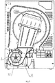
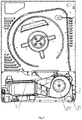
Fig. 1 andFig. 2 , the drying drum and the fan of thedrying fan 1 of conventional dryer are all rotated in one direction, and the direction of the effective airflow provided is a single direction. The shape of the blades of thedrying fan 1 and the volute are designed based on the evolvent principle. The direction of the rotation of thefan 12 is rotated towards the direction closing to the volute tongue of the volute (as shown inFig. 1 and2 , the fan rotates in the counterclockwise direction). Due to the unidirectional rotation of the drying drum, the clothes in the drum are intertwined with each other and cannot be completely shaken and unfold. As a result, the drying efficiency is relatively low, the drying uniformity does not reach the ideal state, and the drying clothes are unevenly dried. - The present disclosure is proposed due to all the above.
- The technical problem to be solved by the present disclosure is to overcome the shortcomings of the prior art by providing the dryer, its drying drum and drying fan both are able to rotate clockwise and anti-clockwise for improving the drying efficiency and the drying uniformity of the drying clothes.
- In order to solve the above technical problem, the basic conception of the technical solution adopted by the present disclosure is as follows:
A dryer comprises a drying drum, a drum motor driving the drying drum to rotate, and a drying fan for making dried hot air enter into the drying drum. The drying fan comprises a volute, a fan disposed in the volute, and a drying motor driving the fans to rotate. The drum motor and the drying motor share one motor, and the motor is capable of forward and reverse rotation. The motor drives the drum and the fan to rotate forward and reversely. The amount of air flow passed by the fan is same in both cases of forward and reverse rotation. - Furthermore, the volute of the drying fan comprises two parts which are a first case and a second case, and is formed by connecting the two parts in snap-fit pattern in an axial direction of the fan. An air inlet is arranged at the first case in the axial direction of the fan, and an air outlet is arranged at the volute in a radial direction of the fan.
- Furthermore, the second case of the volute of the drying fan comprises a bottom plate, and a side plate mounted on one side of the bottom plate. The side plate encloses a circular-like contour which is formed by connecting a plurality of involute contours. An opening is configured on the circular-like contour, and each of two outward sides of the opening is outward provided with a straight plate. The two straight plates are respectively tangent to the circular-like contour on both sides of the opening to form an U-shaped contour. An area between the two straight plates communicates with the opening to form an air outlet of the volute. The fan is arranged in the circular-like contour.
- Furthermore, the second case of the volute of the drying fan comprises a bottom plate and a side plate mounted on one side of the bottom plate. The side plate encloses a circular contour, and an opening is configured on the circular contour. And each of two outward sides of the opening is outward provided with a straight plate. The two straight plates are respectively tangent to the circular contour on both sides of the opening to form an U-shaped contour. An area between the two straight plates communicates with the opening to form an air outlet of the volute. The fan is arranged in the circular contour, and located at the center of the circular contour.
- Furthermore, the first case of the volute of the drying fan has an U-shaped contour that matches with the second volute.
- Furthermore, the dryer has a condensation function, and the dryer comprises a condenser and a condensate fan. The condensate fan provides cooling air to the condenser. The condensate fan comprises a volute, a fan arranged in the volute, and a condensate motor driving the fan to rotate. The condensate motor, the drum motor and the drying motor share one motor. The condensate fan reversibly rotates along with the drying motor, and the amount of air flow passed by the condensate fan is same in both cases of forward and reverse rotation.
- Furthermore, the volute of the condensate fan comprises two parts which are a first case and a second case, and is formed by connecting the two parts in snap-fit pattern in an axial direction of the fan. An air inlet is arranged at the first case in the axial direction of the fan, and an air outlet is arranged at the volute in a radial direction of the fan.
- Furthermore, the second case of the volute of the condensate fan comprises the bottom plate, and a side plate mounted on one side of the bottom plate. The side plate encloses a circular-like contour which is formed by connecting a plurality of involute contours. An opening is configured on the circular-like contour, and each of two sides of the opening is outward provided with a straight plate. The two straight plates are respectively tangent to the circular-like contour on both sides of the opening to form an U-shaped contour. An area between the two straight plates communicates with the opening to form an air outlet of the volute. The fan is arranged in the circular-like contour.
- Furthermore, the second case of the volute of the condensate fan comprises a bottom plate and a side plate mounted on one side of the bottom plate. The side plate encloses a circular contour, and an opening is configured on the circular contour. And two straight plates are set outwards from the opening. The two straight plates are respectively tangent to the circular contour on both sides of the opening to form an U-shaped contour. An area between the two straight plates forms an outlet volute. The fan is arranged in the circular contour, and located at the center of the circular contour.
- Furthermore, the first case of the volute of the condensate fan has an U-shaped contour that matches with the second volute.
- After adopting the above technical solutions, the present disclosure has the following beneficial effects compared with the prior art.
- The dryer of the present disclosure comprises the drying fan and the drying drum, and the air outlet of the drying fan communicates with the air inlet of the drying drum by the air duct. The drying fan comprises the volute, the fan, and the drying motor driving the fan to rotate. The drying drum and the drying fan both are able to rotate clockwise and anti-clockwise, and both are driven by the same motor. In this way, the cost is saved. As the drying drum are able to rotate clockwise and anti-clockwise, the laundry in the drying drum is more effectively shaken, so that the drying efficiency is higher and the drying is more uniform.
- The embodiments of the present disclosure are described in further detail below with reference to the accompanying drawings.
-
-
Fig.1 is the installation diagram of the drying fan and the condensate fan in the dryer in the prior art; -
Fig. 2 is the installation diagram of the drying fan in the dryer in the prior art; -
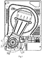
Fig. 3 is the installation diagram of the condensate fan in the dryer in the prior art; -
Fig.4 is the installation diagram of the drying fan in the dryer in the present disclosure; -
Fig.5 is an enlarged schematic view of part C inFig.4 ; -
Fig. 6 is the installation diagram of the condensate fan in the dryer in the present disclosure. -
Fig.7 is an enlarged schematic view of part B inFig.6 ; -
Fig.8 is the installation diagram of the drying fan inembodiment 1 and 6 in the dryer in the present disclosure; -
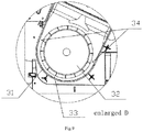
Fig.9 is an enlarged schematic view of part D inFig. 8 .
1.drying fan 11.volute 12.fan 2.condensate fan 21.volute 22.fan 3.drying fan 31.volute 32.fan 33.gap 34.gap 4.condensate fan 41.volute 42.fan 5.condenser - Due to the drying drum of the existing dryer can only rotate in one direction, the shaking degree of the clothes in the drying drum is limited. In order to make the degree of shaking of the clothes better, to improve the drying efficiency, and to improve the drying uniformity, both of the drying drum and the drying
fan 3 in the dryer of the present disclosure are able to rotate clockwise and anti-clockwise. In addition, the fan provides equal amount of air when it rotates clockwise and anti-clockwise. This structure is able to apply to all kinds of dryers that equipped with drying drum and drying fan. - Some of the dryers are vented dryers, and the indoor air in the room where the clothes dryer is located is sucked into the drying
fan 3 of the dryer through the air inlet of the dryer. After the indoor air is heated by the heating device installed in the drying air tunnel, the indoor air enters into the drying drum of the dryer by the drying air tunnel. Then the air dries the clothes in the drying drum, and discharges from the air outlet of the dryer. Repeating the above actions achieves clothes drying. The dryer of the present disclosure may be this type, and the dryer comprises the drying drum, the drum motor that drives the drying drum to rotate, and the drying fan for making dried hot air enter into the drying drum. The drying drum comprises a volute, a fan arranged inside the spiral casting, and a drying motor driving the fans rotate. The drum motor and the drying motor share one motor, and the motor is capable of forward and reverse rotation. The motor drives the drum and the fan to rotate forward and reversely. The amount of air flow passed by the fan is same in both cases of forward and reverse rotation. - The volute of the drying fan of this type dryer comprises two parts which are the first case and the second case, and is formed by connecting the two parts in snap-fit pattern in an axial direction of the fan. An air inlet is arranged on the first case in the axial direction of the fan, and an air outlet is arranged on the volute in a radial direction of the fan.
- The second case of the volute of the drying fan comprises the bottom plate and the side plate mounted on one side of the bottom plate. The side plate encloses a circular contour, and the circular contour is provided with an opening. And each outward side of the opening is provided with a straight plate. The two straight plates are respectively tangent to the circular contour on both sides of the opening to form a U-shaped contour. An area between the two straight plates communicates with the opening to form an air outlet of the volute. The fan is arranged in the circular contour, and located at the center of the circular contour. The first case of the volute of the drying fan has a U-shaped contour that matches with the second volute.
- Some dryers are heat-pump dryers, and comprise the drying drum, the drying motor that drives the drying drum to rotate, and the drying fan for making dried hot air enter into the drying drum. The drying fan communicates with the drying drum by closed cyclic air duct, and the heating device is arranged in the cyclic air duct between the air outlet of the drying fan and the air inlet of the drying drum. The drying fan comprises the volute, the fan arranged in the volute, and the drying motor driving the fans rotate. The drum motor and the drying motor share one motor, and the motor is capable of forward and reverse rotation. The motor drives the drum and the fan to rotate forward and reversely. The amount of air flow passed by the fan is same in both cases of forward and reverse rotation.
- The volute of the drying fan of this type dryer comprises two parts which are the first case and the second case, and is formed by connecting the two parts in snap-fit pattern in an axial direction of the fan. An air inlet with bell opening shape is arranged at the first case in the axial direction of the fan, and an air outlet is arranged at the volute in a radial direction of the fan. The second case of the volute of the drying fan comprises the bottom plate and the side plate mounted on one side of the bottom plate. The side plate encloses circular contours, and the circular contour is provided with an opening. And each outward sides of the opening is provided with a straight plate. The two straight plates are respectively tangent to the circular contour on both sides of the opening to form a U-shaped contour. An area between the two straight plates communicates with the opening to form an air outlet of the volute. The fans are arranged in the circular contour, and locate at the center of the circular contour. The first case of the volute of the drying fan has an U-shaped contour that matches with the second volute.
- Some dryers are with condensation function, and this type of dryers is provided with the condenser and the condensate fan.
- The dryer of the present disclosure comprises the drying drum, the drum motor driving the drying drum to rotate, the drying
fan 3, thecondenser 5, and the condensate fan 4, and the air outlet of the dryingfan 3 communicates with the air inlet of the drying drum by the air duct. - The drying drum, the
condenser 5, and the dryingfan 3 are successively connected by the air duct to form the drying cyclic air duct, and the condensate fan 4 for making the cooling cold air enter into thecondenser 5. The air in the drying cyclic air duct is isolated from the cooling cold air passing through thecondenser 5. - As shown in
Fig.4 andFig.5 , the dryingfan 3 comprises thevolute 31, thefan 32, and the drying motor driving the fan to rotate, and the center axis of thevolute 31 is coaxial with the center axis of thefan 32. Both thevolute 31 and thefan 32 have a symmetrical structure. - The
volute 31 of the dryingfan 3 comprises the first case and the second case, and is formed by connecting the two parts in snap-fit pattern in an axial direction of the fan. An air inlet with the bell opening shape is arranged at the first case in the axial direction of the fan, and an air outlet is arranged at the volute in the radial direction of the fan. The air inlet with the bell opening shape means that the end of the air inlet facing the fan has a small diameter, and the end facing away from the fan has a large diameter and resembles a bell mouth. - The second case of the
volute 31 of the drying fan comprises the bottom plate and the side plate mounted on one side of the bottom plate. The side plate encloses the circular contour, and the circular contour is provided with an opening. And each outward sides of the opening is provided with a straight plate. The two straight plates are respectively tangent to the circular contour on both sides of the opening to form an U-shaped contour. An area between the two straight plates forms an air outlet of the volute. The fan is arranged in the circular contour, and located at the center of the circular contour. - The first case of the volute of the drying fan has a U-shaped contour that matches with the second volute.
- The blades of the
fan 32 of the dryingfan 3 are straight blades extending in the radial direction of the fan. The blade surfaces are parallel to the central axis that is the rotation axis of thefan 32. - As shown in
Fig.6 and7 , the condensate fan 4 comprises thevolute 41, thefan 42, and the condensate motor driving the fan to rotate. The center axis of thevolute 41 is coaxial with the center axis of thefan 42. Both thevolute 41 and thefan 42 have a symmetrical structure. - The
volute 41 of the condensate fan 4 comprises the first case and the second case, and is formed by connecting the two parts in snap-fit pattern in an axial direction of the fan. An air inlet with bell opening shape is arranged at the first case in the axial direction of the fan, and an air outlet is arranged at the volute in the radial direction of the fan. - The second case of the
volute 41 of the condensate fan 4 comprises the bottom plate and the side plate mounted on one side of the bottom plate. The side plate encloses the circular contour, and the circular contour is provided with an opening. Each of two sides of the opening is outward provided with a straight plate. The two straight plates are respectively tangent to the circular contour on both sides of the opening to form an U-shaped contour. An area between the two straight plates communicates with the opening to form an air outlet of the volute. The fan is arranged inside the circular contour, and located at the center of the circular contour. The first case of thevolute 41 of the condensate fan has an U-shaped contour that matches with the second volute. - The blades of the
fan 42 of the condensate fan 4 are straight blades extending in the radial direction of the fan. The blade surfaces are parallel to the central axis of thefan 32. - The condensate fan of the present disclosure is different from the condensate fan of a conventional dryer equipping with a condenser and a condensate fan. In the conventional dryer, as shown in
Fig.3 , the design of the blades of thecondensate fan 2 and the shapes of the volute is based on the evolvent principle, and the direction is the same as the rotation direction of thefan 22. - The heating device is arranged in the drying cyclic air tunnel between the condenser and the drying fan.
- In order to reduce the complexity of the dryer and reduce energy consumption, the condensate motor, the drum motor and the drying motor share one motor, so that the drying drum, the fan of the drying fan and the fan of the condensate fan can all rotate in the same direction.
- The dryer of the present disclosure comprises the drying fan, the drying drum, the condenser, and the condensate fan, and the air outlet of the drying fan communicates with the air inlet of the drying drum by the air duct. The drying drum, the condenser, and the drying fan are successively connected by the air duct to form the drying cyclic air duct, and the condensate fan provides the cooling cold air for the condenser. The drying fan comprises the volute and the fan. The central axis of the volute is coaxial with the central axis of the fan. The condensate fan comprises the volute and the fan. The central axis of the volute is coaxial with the central axis of the fan. The condensate motor, the drum motor, and the drying motor are the same motor to reduce the equipment load and the energy consumption. The drying drum, the fan of the drying fan, and the fan of the condensate fan are all able to clockwise and anti-clockwise rotate. As the drying drum are able to rotate clockwise and anti-clockwise,the laundry in the drying drum is more effectively shaken and more uniform dried with a higher drying efficiency. The drying fan provides power for the drying circulation air entering and exiting the drying drum, and the condensate fan provides the cooling air for the condenser. In this way, the hot and damp drying circulation air from the drying drum is cooled and dehumidified at the condenser. The volute and the blades of the drying fan and the condensate fan are symmetrical. During the drying drum rotating clockwise or anticlockwise, the drying fans are able to effectively provide power to the air inside the drying drum for circulation through the drying cyclic air duct. The condensate fans are able to effectively provide power to the cooler air outside the dryer to flow to the condenser. It will not be able to provide effective air flow for both directions of rotation when the drying fan and the condenser fan in the existing clothes dryer are reversed due to the involute design of the volute and the fan.
- The differences between the present embodiment with the
embodiment
As shown inFig.8 and9 , the second case of the spiral casting 31 of the drying fan comprises the bottom plate, and the side plate mounted on one side of the bottom plate. The side plate encloses a circular-like contour which is formed by connecting a plurality of involute contours. An opening is configured on this type of circular-like contour, and each of two sides of the opening is outward provided with a straight plate. The two straight plates are respectively tangent to the circular-like contour on both sides of the opening to form a U-shaped contour. The area between the two straight plates is communicated with the opening to form an air outlet of the volute. The fan is arranged inside the circular-like contour, and the central axis of thefan 32 located at the centre of the circular-like contour at the side away from the air outlet. Namely, thegap 33 between the volute 31 and thefan 32 gradually increases toward the air outlet from the bottom of the U-shaped contour, so that a better air pressure can be formed and the flow amount of the cyclic air can be increased. - The differences between the present embodiments with the
embodiment 3 are as following:
The second case of the spiral casting 41 of the condensate fan comprises the bottom plate, and the side plate mounted on one side of the bottom plate. The side plate encloses a circular-like contour which is formed by connecting a plurality of involute contours. An opening is configured on this type of circular-like contour, and each of two sides of the opening is outward provided with a straight plate. The two straight plates are respectively tangent to the circular-like contour on both sides of the opening to form an U-shaped contour. The area between two straight plates is communicated with the opening to form an air outlet of thevolute 41. Fans are arranged inside the circular-like contour, and the central axis of thefan 42 located at the centre of the circular-like contour at the side away from the air outlet. Namely, the gap between the volute 41 and thefan 42 gradually increases toward the air outlet from the bottom of the U-shaped contour, so that a better air pressure can be formed and the flow amount of the cyclic air can be increased. - The differences between the present embodiments with the
embodiment 3 are as following:
As shown inFig.8 and9 , the second case of thevolute 31 of the drying fan comprises the bottom plate, and the side plate mounted on one side of the bottom plate. The side plate encloses a circular-like contour which is formed by connecting a plurality of involute contours. An opening is configured on this type of circular-like contour, and each of two sides of the opening is outward provided with a straight plate. The two straight plates are tangent to the circular-like contour on both sides of the opening to form an U-shaped contour. The area between the two straight plates communicates with the opening to form an air outlet of the volute. Fans are arranged inside the circular-like contour, and the central axis of thefan 32 located at the centre of the circular-like contour at the side away from the air outlet. Namely, thegap 33 between the volute 31 and thefan 32 gradually increases toward the air outlet from the bottom of the U-shaped contour, so that a better air pressure can be formed and the flow amount of the cyclic air can be increased. Thegap 33 is the smallest gap between the volute 31 and thefan 32, while thegap 34 next to the air outlet is between the volute 31 and thefan 32. From thegap 33 to thegap 34, the gap gradually increases. - The second case of the spiral casting 41 of the condensate fan comprises the bottom plate, and the side plate mounted on one side of the bottom plate. The side plate encloses a circular-like contour which is formed by connecting a plurality of involute contours. An opening is configured on this type of circular-like contour, and each of two sides of the opening is outward provided with a straight plate. The two straight plates are respectively tangent to the circular-like contour on both sides of the opening to form an U-shaped contour. The area between the two straight plates communicates with the opening to form an air outlet of the volute. Fans are arranged inside the circular-like contour, and the central axis of the
fan 42 located at the centre of the circular-like contour at the side away from the air outlet. Namely, the gap between the volute 41 and thefan 42 gradually increases toward the air outlet from the bottom of the U-shaped contour, so that a better air pressure can be formed and the flow amount of the cyclic air can be increased. - The embodiments in the above embodiments may be further combined or substituted, and the embodiments are merely for describing the preferred embodiments of the present disclosure, and are not intended to limit the conception and scope of the present disclosure. Without departing from the design concept of the present disclosure, various changes and improvements, made by technical personnel in the technical field of the present disclosure, belong to the protection scope of the present disclosure.
Claims (10)
- A dryer, comprising a drying drum,
a drum motor driving the drying drum to rotate, and
a drying fan for making dried hot air enter into the drying drum;
wherein, the drying fan comprises a volute, a fan disposed in the volute, and a drying motor driving the fan to rotate; the drum motor and the drying motor share one motor,
characterized in that: the motor is capable of forward and reverse rotation, and drives the drying drum and the fan to rotate forward and reversely;
the amount of air flow passed by the fan is same in both cases of forward and reverse rotation. - The dryer according to claim 1, characterized in that:the volute of the drying fan comprises two parts which are a first case and a second case, and is formed by connecting the two parts in snap-fit pattern in an axial direction of the fan;an air inlet is arranged at the first case in the axial direction of the fan, and an air outlet is arranged at the volute in a radial direction of the fan.
- The dryer according to claim 1, characterized in that:the second case of the volute of the drying fan comprises a bottom plate, and a side plate mounted on one side of the bottom plate;the side plate encloses a circular-like contour which is formed by connecting a plurality of involute contours ;an opening is configured on the circular-like contour,each of two sides of the opening is outward provided with a straight plate;two straight plates are respectively tangent to the circular-like contour on both sides of the opening to form an U-shaped contour;an area between the two straight plates communicates with the opening to form an air outlet of the volute; andthe fan is arranged in the circular-like contour.
- The dryer according to claim 1, characterized in that:the second case of the volute of the drying fan comprises a bottom plate and a side plate mounted on one side of the bottom plate;the side plate encloses a circular contour,an opening is configured on the circular contour;each of two sides of the opening is outward provided with a straight plate;two straight plates are respectively tangent to the circular contour on both sides of the opening to form an U-shaped contour;an area between the two straight plates communicates with the opening to form an air outlet of the volute; andthe fan is arranged in the circular contour, and located at a center of the circular contour.
- The dryer according to claim 3 or 4, characterized in that: the first case of the volute of the drying fan has an U-shaped contour that matches with the second volute.
- The dryer according to any one of claims 1 to 5, characterized in that: the dryer has a condensation function,
the dryer comprises a condenser and a condensate fan; the condensate fan makes cooling air enter into the condenser;
the condensate fan comprises a volute, a fan arranged in the volute, and a condensate motor driving the fan to rotate;
the condensate motor, the drum motor and the drying motor share one motor;
the condensate fan forward and reversely rotates depending on forward and reverse rotation of the drying motor, and
the amount of air flow passed by the condensate fan is same in both cases of forward and reverse rotation. - The dryer according to claim 6, characterized in that:the volute of the condensate fan comprises two parts which are a first case and a second case, and is formed by connecting the two parts in snap-fit pattern in an axial direction of the fan;an air inlet is arranged at the first case in the axial direction of the fan, and an air outlet is arranged at the volute in a radial direction of the fan.
- The dryer according to claim 7, characterized in that:the second case of the volute of the condensate fan comprises a bottom plate, and a side plate mounted on one side of the bottom plate;the side plate encloses a circular-like contour which is formed by connecting a plurality of involute contours;an opening is configured on the circular-like contour,each of two sides of the opening is outward provided with a straight plate;two straight plates are respectively tangent to the circular-like contour on both sides of the opening to form an U-shaped contour;an area between the two straight plates communicates with the opening to form an air outlet of the volute; the fan is arranged in the circular-like contour.
- The dryer according to claim 7, characterized in that: the second case of the volute of the condensate fan comprises a bottom plate and a side plate mounted on one side of the bottom plate;
the side plate encloses a circular contour,
an opening is configured on the circular contour;
two straight plates are set outwards from the opening; the two straight plates are respectively tangent to the circular contour on both sides of the opening to form an U-shaped contour;
an area between the two straight plates forms an air outlet of the volute; and
the fan is arranged in the circular contour, and located at a center of the circular contour. - The dryer according to claim 8 or 9, characterized in that: the first case of the volute of the condensate fan has an U-shaped contour that matches with the second volute.
Applications Claiming Priority (2)
| Application Number | Priority Date | Filing Date | Title |
|---|---|---|---|
| CN201510712368 | 2015-10-28 | ||
| PCT/CN2016/103756 WO2017071638A1 (en) | 2015-10-28 | 2016-10-28 | Clothes-drying machine |
Publications (3)
| Publication Number | Publication Date |
|---|---|
| EP3369858A1 true EP3369858A1 (en) | 2018-09-05 |
| EP3369858A4 EP3369858A4 (en) | 2018-10-17 |
| EP3369858B1 EP3369858B1 (en) | 2022-03-02 |
Family
ID=58631238
Family Applications (1)
| Application Number | Title | Priority Date | Filing Date |
|---|---|---|---|
| EP16859073.5A Active EP3369858B1 (en) | 2015-10-28 | 2016-10-28 | Clothes-drying machine |
Country Status (6)
| Country | Link |
|---|---|
| US (1) | US20190203406A1 (en) |
| EP (1) | EP3369858B1 (en) |
| JP (1) | JP2018531754A (en) |
| KR (1) | KR20180074764A (en) |
| CN (1) | CN106637872B (en) |
| WO (1) | WO2017071638A1 (en) |
Cited By (1)
| Publication number | Priority date | Publication date | Assignee | Title |
|---|---|---|---|---|
| US20190203406A1 (en) * | 2015-10-28 | 2019-07-04 | Qingdao Haier Washing Machine Co., Ltd. | Dryer |
Families Citing this family (10)
| Publication number | Priority date | Publication date | Assignee | Title |
|---|---|---|---|---|
| CN107805927A (en) * | 2016-09-09 | 2018-03-16 | 青岛海尔洗衣机有限公司 | Dryer |
| CN109234991B (en) * | 2017-07-10 | 2021-12-17 | 青岛海尔洗衣机有限公司 | Clothes dryer |
| CN109487507B (en) * | 2017-09-13 | 2021-05-25 | 青岛海尔洗涤电器有限公司 | A clothing treatment device |
| CN111197252A (en) * | 2018-11-19 | 2020-05-26 | 宁波吉德电器有限公司 | Air guide structure of clothes dryer and clothes dryer with air guide structure |
| CN111980940A (en) * | 2019-05-23 | 2020-11-24 | 青岛海尔滚筒洗衣机有限公司 | Centrifugal fans and dryers |
| CN113494007A (en) * | 2020-04-02 | 2021-10-12 | 青岛海尔滚筒洗衣机有限公司 | Clothes drying equipment |
| CN113882123A (en) * | 2020-07-01 | 2022-01-04 | 青岛海尔滚筒洗衣机有限公司 | Clothes drying equipment |
| CN114541112B (en) * | 2020-11-18 | 2025-07-15 | 青岛海尔滚筒洗衣机有限公司 | Air duct structure and clothes dryer |
| CN116122023A (en) * | 2021-11-12 | 2023-05-16 | 广东美的白色家电技术创新中心有限公司 | Clothes dryer |
| CN114808410B (en) * | 2022-05-30 | 2024-06-25 | 海信冰箱有限公司 | Dryer control method and dryer equipment |
Family Cites Families (29)
| Publication number | Priority date | Publication date | Assignee | Title |
|---|---|---|---|---|
| US2742708A (en) * | 1952-07-12 | 1956-04-24 | Gen Motors Corp | Domestic appliance |
| US3034221A (en) * | 1957-10-11 | 1962-05-15 | Gen Motors Corp | Clothes drier having absorbent bed |
| US3309783A (en) * | 1964-03-09 | 1967-03-21 | Gen Electric | Clothes drying machine having reversing drum drive means |
| US3514867A (en) * | 1968-06-21 | 1970-06-02 | Blackstone Corp | Clothes dryers with reversing drum |
| DE1916916C3 (en) * | 1969-04-02 | 1975-08-14 | Hans F. Arendt, Maschinenbau, 7120 Bietigheim | Drum dryer for drying hides, furs, soft leather or the like |
| US4231166A (en) * | 1979-10-09 | 1980-11-04 | General Electric Company | Automatic control for a clothes dryer |
| DE3039685A1 (en) * | 1980-10-21 | 1982-06-09 | Bosch-Siemens Hausgeräte GmbH, 7000 Stuttgart | LAUNDRY DRYER WITH A RADIAL BLOWER |
| US4477984A (en) * | 1980-10-30 | 1984-10-23 | Wilfred O. Schmidt | Multi purpose three pass drum dryer |
| US4586267A (en) * | 1984-08-07 | 1986-05-06 | Intraspec, Inc. | Automated reversible-dryer control system |
| JPS6171099U (en) * | 1984-10-16 | 1986-05-15 | ||
| US4738034A (en) * | 1985-12-16 | 1988-04-19 | Kabushiki Kaisha Toshiba | Drying machine |
| JPS63153100A (en) * | 1986-12-17 | 1988-06-25 | 松下電器産業株式会社 | clothes dryer |
| US4827627A (en) * | 1988-02-22 | 1989-05-09 | American Dryer Corporation | Apparatus and method for controlling a drying cycle of a clothes dryer |
| JP2749371B2 (en) * | 1989-05-20 | 1998-05-13 | 株式会社日立製作所 | Fully automatic washing / drying machine |
| JP3325280B2 (en) * | 1991-10-03 | 2002-09-17 | 松下電器産業株式会社 | Clothes dryer |
| JPH06207594A (en) * | 1992-11-20 | 1994-07-26 | Toto Ltd | Blast device |
| US5555645A (en) * | 1993-03-31 | 1996-09-17 | White Consolidated Industries, Inc. | Reversing clothes dryer and method therefor |
| US5555647A (en) * | 1995-08-23 | 1996-09-17 | White Consolidated Industries, Inc. | Motor mounted to blower housing |
| DE19904993C2 (en) * | 1999-02-08 | 2003-04-17 | Miele & Cie | condensation dryer |
| EP1541744A1 (en) * | 2003-12-11 | 2005-06-15 | Electrolux Home Products Corporation N.V. | Household clothes drying machine with improved condenser |
| CN1724803A (en) * | 2004-07-19 | 2006-01-25 | 乐金电子(天津)电器有限公司 | Condensing type clothes drying machine and its control method |
| SI1630279T1 (en) * | 2004-08-27 | 2007-08-31 | Electrolux Home Prod Corp | High efficiency household clothes drying machine |
| US8872074B2 (en) * | 2007-09-11 | 2014-10-28 | General Electric Company | Centrifugal switch bypass for reverse tumble dryers |
| US8104191B2 (en) * | 2008-07-31 | 2012-01-31 | Electrolux Home Products, Inc. | Laundry dryer providing moisture application during tumbling and reduced airflow |
| DE102009028931A1 (en) * | 2009-08-27 | 2011-03-03 | BSH Bosch und Siemens Hausgeräte GmbH | Method for operating an adsorption dryer and dryer for implementing the method |
| WO2012005534A2 (en) * | 2010-07-09 | 2012-01-12 | Lg Electronics Inc. | Method for operating clothes treating apparatus |
| US8387274B2 (en) * | 2010-07-16 | 2013-03-05 | Whirlpool Corporation | Variable airflow in laundry dryer having variable air inlet |
| EP2918722B1 (en) * | 2014-03-14 | 2021-01-20 | Whirlpool Corporation | Method for treating clothes in a dryer |
| CN106637872B (en) * | 2015-10-28 | 2021-06-11 | 青岛胶南海尔洗衣机有限公司 | Clothes dryer |
-
2016
- 2016-01-29 CN CN201610067234.7A patent/CN106637872B/en active Active
- 2016-10-28 KR KR1020187014783A patent/KR20180074764A/en not_active Ceased
- 2016-10-28 WO PCT/CN2016/103756 patent/WO2017071638A1/en not_active Ceased
- 2016-10-28 JP JP2018522083A patent/JP2018531754A/en active Pending
- 2016-10-28 EP EP16859073.5A patent/EP3369858B1/en active Active
- 2016-10-28 US US15/771,247 patent/US20190203406A1/en not_active Abandoned
Cited By (1)
| Publication number | Priority date | Publication date | Assignee | Title |
|---|---|---|---|---|
| US20190203406A1 (en) * | 2015-10-28 | 2019-07-04 | Qingdao Haier Washing Machine Co., Ltd. | Dryer |
Also Published As
| Publication number | Publication date |
|---|---|
| CN106637872B (en) | 2021-06-11 |
| KR20180074764A (en) | 2018-07-03 |
| JP2018531754A (en) | 2018-11-01 |
| CN106637872A (en) | 2017-05-10 |
| EP3369858A4 (en) | 2018-10-17 |
| EP3369858B1 (en) | 2022-03-02 |
| US20190203406A1 (en) | 2019-07-04 |
| WO2017071638A1 (en) | 2017-05-04 |
Similar Documents
| Publication | Publication Date | Title |
|---|---|---|
| EP3369858B1 (en) | Clothes-drying machine | |
| EP3399093B1 (en) | Integrated washing and drying machine | |
| CN105316919B (en) | A kind of tumble drier and clothes-drying method | |
| US20160115970A1 (en) | Impeller assembly for an appliance | |
| EP3290577A1 (en) | Condensation-based clothes dryer and condensation-based clothes drying method | |
| CN106595248A (en) | Wind-heat type wood drying box | |
| CN107805927A (en) | Dryer | |
| JP2019534737A (en) | Forward / reverse rotating fan for clothes dryer and clothes dryer | |
| EP2883995A1 (en) | Clothes dryer | |
| JP5904919B2 (en) | Washing and drying machine | |
| CN205077292U (en) | Clothes drying machine | |
| BRPI0707934A2 (en) | dual fan household clothes dryers | |
| US9617678B2 (en) | Impeller housing for an appliance | |
| JP2014004043A (en) | Dehumidifying and drying mechanism | |
| CN202214640U (en) | Energy-saving drying roller for clothes dryer | |
| CN100503954C (en) | Drum washing machine with drying function | |
| CN205188659U (en) | Drying washing machine | |
| CN107805928A (en) | Dryer | |
| CN216998934U (en) | Drying power air system of washing machine | |
| CN107761336B (en) | Clothes drying machine | |
| KR20120014531A (en) | Clothes dryer | |
| CN106676853B (en) | Drying washing machine | |
| CN211972780U (en) | Clothes drying equipment | |
| US11421374B2 (en) | Dryer | |
| KR101142775B1 (en) | Clothes drier |
Legal Events
| Date | Code | Title | Description |
|---|---|---|---|
| STAA | Information on the status of an ep patent application or granted ep patent |
Free format text: STATUS: THE INTERNATIONAL PUBLICATION HAS BEEN MADE |
|
| PUAI | Public reference made under article 153(3) epc to a published international application that has entered the european phase |
Free format text: ORIGINAL CODE: 0009012 |
|
| STAA | Information on the status of an ep patent application or granted ep patent |
Free format text: STATUS: REQUEST FOR EXAMINATION WAS MADE |
|
| 17P | Request for examination filed |
Effective date: 20180521 |
|
| AK | Designated contracting states |
Kind code of ref document: A1 Designated state(s): AL AT BE BG CH CY CZ DE DK EE ES FI FR GB GR HR HU IE IS IT LI LT LU LV MC MK MT NL NO PL PT RO RS SE SI SK SM TR |
|
| AX | Request for extension of the european patent |
Extension state: BA ME |
|
| A4 | Supplementary search report drawn up and despatched |
Effective date: 20180914 |
|
| RIC1 | Information provided on ipc code assigned before grant |
Ipc: D06F 58/24 20060101ALN20180911BHEP Ipc: D06F 58/20 20060101ALN20180911BHEP Ipc: D06F 58/08 20060101AFI20180911BHEP |
|
| DAV | Request for validation of the european patent (deleted) | ||
| DAX | Request for extension of the european patent (deleted) | ||
| STAA | Information on the status of an ep patent application or granted ep patent |
Free format text: STATUS: EXAMINATION IS IN PROGRESS |
|
| 17Q | First examination report despatched |
Effective date: 20200708 |
|
| GRAP | Despatch of communication of intention to grant a patent |
Free format text: ORIGINAL CODE: EPIDOSNIGR1 |
|
| STAA | Information on the status of an ep patent application or granted ep patent |
Free format text: STATUS: GRANT OF PATENT IS INTENDED |
|
| RIC1 | Information provided on ipc code assigned before grant |
Ipc: D06F 58/02 20060101ALN20211015BHEP Ipc: D06F 58/24 20060101ALN20211015BHEP Ipc: D06F 58/20 20060101ALN20211015BHEP Ipc: D06F 58/08 20060101AFI20211015BHEP |
|
| INTG | Intention to grant announced |
Effective date: 20211110 |
|
| GRAS | Grant fee paid |
Free format text: ORIGINAL CODE: EPIDOSNIGR3 |
|
| GRAA | (expected) grant |
Free format text: ORIGINAL CODE: 0009210 |
|
| STAA | Information on the status of an ep patent application or granted ep patent |
Free format text: STATUS: THE PATENT HAS BEEN GRANTED |
|
| AK | Designated contracting states |
Kind code of ref document: B1 Designated state(s): AL AT BE BG CH CY CZ DE DK EE ES FI FR GB GR HR HU IE IS IT LI LT LU LV MC MK MT NL NO PL PT RO RS SE SI SK SM TR |
|
| REG | Reference to a national code |
Ref country code: GB Ref legal event code: FG4D |
|
| REG | Reference to a national code |
Ref country code: CH Ref legal event code: EP Ref country code: AT Ref legal event code: REF Ref document number: 1472311 Country of ref document: AT Kind code of ref document: T Effective date: 20220315 |
|
| REG | Reference to a national code |
Ref country code: DE Ref legal event code: R096 Ref document number: 602016069697 Country of ref document: DE |
|
| REG | Reference to a national code |
Ref country code: IE Ref legal event code: FG4D |
|
| REG | Reference to a national code |
Ref country code: LT Ref legal event code: MG9D |
|
| REG | Reference to a national code |
Ref country code: NL Ref legal event code: MP Effective date: 20220302 |
|
| PG25 | Lapsed in a contracting state [announced via postgrant information from national office to epo] |
Ref country code: SE Free format text: LAPSE BECAUSE OF FAILURE TO SUBMIT A TRANSLATION OF THE DESCRIPTION OR TO PAY THE FEE WITHIN THE PRESCRIBED TIME-LIMIT Effective date: 20220302 Ref country code: RS Free format text: LAPSE BECAUSE OF FAILURE TO SUBMIT A TRANSLATION OF THE DESCRIPTION OR TO PAY THE FEE WITHIN THE PRESCRIBED TIME-LIMIT Effective date: 20220302 Ref country code: NO Free format text: LAPSE BECAUSE OF FAILURE TO SUBMIT A TRANSLATION OF THE DESCRIPTION OR TO PAY THE FEE WITHIN THE PRESCRIBED TIME-LIMIT Effective date: 20220602 Ref country code: LT Free format text: LAPSE BECAUSE OF FAILURE TO SUBMIT A TRANSLATION OF THE DESCRIPTION OR TO PAY THE FEE WITHIN THE PRESCRIBED TIME-LIMIT Effective date: 20220302 Ref country code: HR Free format text: LAPSE BECAUSE OF FAILURE TO SUBMIT A TRANSLATION OF THE DESCRIPTION OR TO PAY THE FEE WITHIN THE PRESCRIBED TIME-LIMIT Effective date: 20220302 Ref country code: ES Free format text: LAPSE BECAUSE OF FAILURE TO SUBMIT A TRANSLATION OF THE DESCRIPTION OR TO PAY THE FEE WITHIN THE PRESCRIBED TIME-LIMIT Effective date: 20220302 Ref country code: BG Free format text: LAPSE BECAUSE OF FAILURE TO SUBMIT A TRANSLATION OF THE DESCRIPTION OR TO PAY THE FEE WITHIN THE PRESCRIBED TIME-LIMIT Effective date: 20220602 |
|
| REG | Reference to a national code |
Ref country code: AT Ref legal event code: MK05 Ref document number: 1472311 Country of ref document: AT Kind code of ref document: T Effective date: 20220302 |
|
| PG25 | Lapsed in a contracting state [announced via postgrant information from national office to epo] |
Ref country code: PL Free format text: LAPSE BECAUSE OF FAILURE TO SUBMIT A TRANSLATION OF THE DESCRIPTION OR TO PAY THE FEE WITHIN THE PRESCRIBED TIME-LIMIT Effective date: 20220302 Ref country code: LV Free format text: LAPSE BECAUSE OF FAILURE TO SUBMIT A TRANSLATION OF THE DESCRIPTION OR TO PAY THE FEE WITHIN THE PRESCRIBED TIME-LIMIT Effective date: 20220302 Ref country code: GR Free format text: LAPSE BECAUSE OF FAILURE TO SUBMIT A TRANSLATION OF THE DESCRIPTION OR TO PAY THE FEE WITHIN THE PRESCRIBED TIME-LIMIT Effective date: 20220603 Ref country code: FI Free format text: LAPSE BECAUSE OF FAILURE TO SUBMIT A TRANSLATION OF THE DESCRIPTION OR TO PAY THE FEE WITHIN THE PRESCRIBED TIME-LIMIT Effective date: 20220302 |
|
| PG25 | Lapsed in a contracting state [announced via postgrant information from national office to epo] |
Ref country code: NL Free format text: LAPSE BECAUSE OF FAILURE TO SUBMIT A TRANSLATION OF THE DESCRIPTION OR TO PAY THE FEE WITHIN THE PRESCRIBED TIME-LIMIT Effective date: 20220302 |
|
| PG25 | Lapsed in a contracting state [announced via postgrant information from national office to epo] |
Ref country code: SM Free format text: LAPSE BECAUSE OF FAILURE TO SUBMIT A TRANSLATION OF THE DESCRIPTION OR TO PAY THE FEE WITHIN THE PRESCRIBED TIME-LIMIT Effective date: 20220302 Ref country code: SK Free format text: LAPSE BECAUSE OF FAILURE TO SUBMIT A TRANSLATION OF THE DESCRIPTION OR TO PAY THE FEE WITHIN THE PRESCRIBED TIME-LIMIT Effective date: 20220302 Ref country code: RO Free format text: LAPSE BECAUSE OF FAILURE TO SUBMIT A TRANSLATION OF THE DESCRIPTION OR TO PAY THE FEE WITHIN THE PRESCRIBED TIME-LIMIT Effective date: 20220302 Ref country code: PT Free format text: LAPSE BECAUSE OF FAILURE TO SUBMIT A TRANSLATION OF THE DESCRIPTION OR TO PAY THE FEE WITHIN THE PRESCRIBED TIME-LIMIT Effective date: 20220704 Ref country code: EE Free format text: LAPSE BECAUSE OF FAILURE TO SUBMIT A TRANSLATION OF THE DESCRIPTION OR TO PAY THE FEE WITHIN THE PRESCRIBED TIME-LIMIT Effective date: 20220302 Ref country code: CZ Free format text: LAPSE BECAUSE OF FAILURE TO SUBMIT A TRANSLATION OF THE DESCRIPTION OR TO PAY THE FEE WITHIN THE PRESCRIBED TIME-LIMIT Effective date: 20220302 Ref country code: AT Free format text: LAPSE BECAUSE OF FAILURE TO SUBMIT A TRANSLATION OF THE DESCRIPTION OR TO PAY THE FEE WITHIN THE PRESCRIBED TIME-LIMIT Effective date: 20220302 |
|
| PG25 | Lapsed in a contracting state [announced via postgrant information from national office to epo] |
Ref country code: IS Free format text: LAPSE BECAUSE OF FAILURE TO SUBMIT A TRANSLATION OF THE DESCRIPTION OR TO PAY THE FEE WITHIN THE PRESCRIBED TIME-LIMIT Effective date: 20220702 Ref country code: AL Free format text: LAPSE BECAUSE OF FAILURE TO SUBMIT A TRANSLATION OF THE DESCRIPTION OR TO PAY THE FEE WITHIN THE PRESCRIBED TIME-LIMIT Effective date: 20220302 |
|
| REG | Reference to a national code |
Ref country code: DE Ref legal event code: R097 Ref document number: 602016069697 Country of ref document: DE |
|
| PLBE | No opposition filed within time limit |
Free format text: ORIGINAL CODE: 0009261 |
|
| STAA | Information on the status of an ep patent application or granted ep patent |
Free format text: STATUS: NO OPPOSITION FILED WITHIN TIME LIMIT |
|
| PG25 | Lapsed in a contracting state [announced via postgrant information from national office to epo] |
Ref country code: DK Free format text: LAPSE BECAUSE OF FAILURE TO SUBMIT A TRANSLATION OF THE DESCRIPTION OR TO PAY THE FEE WITHIN THE PRESCRIBED TIME-LIMIT Effective date: 20220302 |
|
| 26N | No opposition filed |
Effective date: 20221205 |
|
| PG25 | Lapsed in a contracting state [announced via postgrant information from national office to epo] |
Ref country code: SI Free format text: LAPSE BECAUSE OF FAILURE TO SUBMIT A TRANSLATION OF THE DESCRIPTION OR TO PAY THE FEE WITHIN THE PRESCRIBED TIME-LIMIT Effective date: 20220302 |
|
| PG25 | Lapsed in a contracting state [announced via postgrant information from national office to epo] |
Ref country code: MC Free format text: LAPSE BECAUSE OF FAILURE TO SUBMIT A TRANSLATION OF THE DESCRIPTION OR TO PAY THE FEE WITHIN THE PRESCRIBED TIME-LIMIT Effective date: 20220302 |
|
| REG | Reference to a national code |
Ref country code: CH Ref legal event code: PL |
|
| REG | Reference to a national code |
Ref country code: BE Ref legal event code: MM Effective date: 20221031 |
|
| PG25 | Lapsed in a contracting state [announced via postgrant information from national office to epo] |
Ref country code: LU Free format text: LAPSE BECAUSE OF NON-PAYMENT OF DUE FEES Effective date: 20221028 |
|
| PG25 | Lapsed in a contracting state [announced via postgrant information from national office to epo] |
Ref country code: LI Free format text: LAPSE BECAUSE OF NON-PAYMENT OF DUE FEES Effective date: 20221031 Ref country code: CH Free format text: LAPSE BECAUSE OF NON-PAYMENT OF DUE FEES Effective date: 20221031 |
|
| PG25 | Lapsed in a contracting state [announced via postgrant information from national office to epo] |
Ref country code: BE Free format text: LAPSE BECAUSE OF NON-PAYMENT OF DUE FEES Effective date: 20221031 |
|
| PG25 | Lapsed in a contracting state [announced via postgrant information from national office to epo] |
Ref country code: IE Free format text: LAPSE BECAUSE OF NON-PAYMENT OF DUE FEES Effective date: 20221028 |
|
| PG25 | Lapsed in a contracting state [announced via postgrant information from national office to epo] |
Ref country code: HU Free format text: LAPSE BECAUSE OF FAILURE TO SUBMIT A TRANSLATION OF THE DESCRIPTION OR TO PAY THE FEE WITHIN THE PRESCRIBED TIME-LIMIT; INVALID AB INITIO Effective date: 20161028 |
|
| PG25 | Lapsed in a contracting state [announced via postgrant information from national office to epo] |
Ref country code: CY Free format text: LAPSE BECAUSE OF FAILURE TO SUBMIT A TRANSLATION OF THE DESCRIPTION OR TO PAY THE FEE WITHIN THE PRESCRIBED TIME-LIMIT Effective date: 20220302 |
|
| PG25 | Lapsed in a contracting state [announced via postgrant information from national office to epo] |
Ref country code: MK Free format text: LAPSE BECAUSE OF FAILURE TO SUBMIT A TRANSLATION OF THE DESCRIPTION OR TO PAY THE FEE WITHIN THE PRESCRIBED TIME-LIMIT Effective date: 20220302 |
|
| PG25 | Lapsed in a contracting state [announced via postgrant information from national office to epo] |
Ref country code: MT Free format text: LAPSE BECAUSE OF FAILURE TO SUBMIT A TRANSLATION OF THE DESCRIPTION OR TO PAY THE FEE WITHIN THE PRESCRIBED TIME-LIMIT Effective date: 20220302 |
|
| PG25 | Lapsed in a contracting state [announced via postgrant information from national office to epo] |
Ref country code: TR Free format text: LAPSE BECAUSE OF FAILURE TO SUBMIT A TRANSLATION OF THE DESCRIPTION OR TO PAY THE FEE WITHIN THE PRESCRIBED TIME-LIMIT Effective date: 20220302 |
|
| PGFP | Annual fee paid to national office [announced via postgrant information from national office to epo] |
Ref country code: DE Payment date: 20251020 Year of fee payment: 10 |
|
| PGFP | Annual fee paid to national office [announced via postgrant information from national office to epo] |
Ref country code: GB Payment date: 20251029 Year of fee payment: 10 |
|
| PGFP | Annual fee paid to national office [announced via postgrant information from national office to epo] |
Ref country code: IT Payment date: 20251031 Year of fee payment: 10 |
|
| PGFP | Annual fee paid to national office [announced via postgrant information from national office to epo] |
Ref country code: FR Payment date: 20251023 Year of fee payment: 10 |