EP3369349A1 - Flexible room divider - Google Patents
Flexible room divider Download PDFInfo
- Publication number
- EP3369349A1 EP3369349A1 EP18179014.8A EP18179014A EP3369349A1 EP 3369349 A1 EP3369349 A1 EP 3369349A1 EP 18179014 A EP18179014 A EP 18179014A EP 3369349 A1 EP3369349 A1 EP 3369349A1
- Authority
- EP
- European Patent Office
- Prior art keywords
- elements
- vertical
- room divider
- fixing
- fastening
- Prior art date
- Legal status (The legal status is an assumption and is not a legal conclusion. Google has not performed a legal analysis and makes no representation as to the accuracy of the status listed.)
- Withdrawn
Links
- 238000004519 manufacturing process Methods 0.000 claims description 6
- 239000002023 wood Substances 0.000 claims description 3
- 239000000463 material Substances 0.000 description 8
- 125000006850 spacer group Chemical group 0.000 description 5
- 239000002184 metal Substances 0.000 description 4
- 238000010276 construction Methods 0.000 description 3
- 239000004033 plastic Substances 0.000 description 3
- 229920003023 plastic Polymers 0.000 description 3
- 238000007789 sealing Methods 0.000 description 3
- 238000006073 displacement reaction Methods 0.000 description 2
- 229920001971 elastomer Polymers 0.000 description 2
- 229920001084 poly(chloroprene) Polymers 0.000 description 2
- 239000000853 adhesive Substances 0.000 description 1
- 238000004026 adhesive bonding Methods 0.000 description 1
- 230000001070 adhesive effect Effects 0.000 description 1
- 239000011324 bead Substances 0.000 description 1
- 230000000295 complement effect Effects 0.000 description 1
- 239000000806 elastomer Substances 0.000 description 1
- 239000011796 hollow space material Substances 0.000 description 1
- 238000007373 indentation Methods 0.000 description 1
- 238000005304 joining Methods 0.000 description 1
- 238000005192 partition Methods 0.000 description 1
- 239000011049 pearl Substances 0.000 description 1
- 230000008447 perception Effects 0.000 description 1
- 230000002093 peripheral effect Effects 0.000 description 1
- 230000000284 resting effect Effects 0.000 description 1
- 239000005060 rubber Substances 0.000 description 1
- 238000000926 separation method Methods 0.000 description 1
- 230000006641 stabilisation Effects 0.000 description 1
- 238000011105 stabilization Methods 0.000 description 1
- 229920003051 synthetic elastomer Polymers 0.000 description 1
- 229920001059 synthetic polymer Polymers 0.000 description 1
- 239000005061 synthetic rubber Substances 0.000 description 1
Images


Classifications
-
- A—HUMAN NECESSITIES
- A47—FURNITURE; DOMESTIC ARTICLES OR APPLIANCES; COFFEE MILLS; SPICE MILLS; SUCTION CLEANERS IN GENERAL
- A47G—HOUSEHOLD OR TABLE EQUIPMENT
- A47G5/00—Screens; Draught-deflectors
-
- E—FIXED CONSTRUCTIONS
- E04—BUILDING
- E04B—GENERAL BUILDING CONSTRUCTIONS; WALLS, e.g. PARTITIONS; ROOFS; FLOORS; CEILINGS; INSULATION OR OTHER PROTECTION OF BUILDINGS
- E04B2/00—Walls, e.g. partitions, for buildings; Wall construction with regard to insulation; Connections specially adapted to walls
- E04B2/74—Removable non-load-bearing partitions; Partitions with a free upper edge
- E04B2/7401—Removable non-load-bearing partitions; Partitions with a free upper edge assembled using panels without a frame or supporting posts, with or without upper or lower edge locating rails
- E04B2/7405—Removable non-load-bearing partitions; Partitions with a free upper edge assembled using panels without a frame or supporting posts, with or without upper or lower edge locating rails with free upper edge, e.g. for use as office space dividers
-
- E—FIXED CONSTRUCTIONS
- E04—BUILDING
- E04B—GENERAL BUILDING CONSTRUCTIONS; WALLS, e.g. PARTITIONS; ROOFS; FLOORS; CEILINGS; INSULATION OR OTHER PROTECTION OF BUILDINGS
- E04B2/00—Walls, e.g. partitions, for buildings; Wall construction with regard to insulation; Connections specially adapted to walls
- E04B2/74—Removable non-load-bearing partitions; Partitions with a free upper edge
- E04B2/7407—Removable non-load-bearing partitions; Partitions with a free upper edge assembled using frames with infill panels or coverings only; made-up of panels and a support structure incorporating posts
- E04B2/7416—Removable non-load-bearing partitions; Partitions with a free upper edge assembled using frames with infill panels or coverings only; made-up of panels and a support structure incorporating posts with free upper edge, e.g. for use as office space dividers
- E04B2/7422—Removable non-load-bearing partitions; Partitions with a free upper edge assembled using frames with infill panels or coverings only; made-up of panels and a support structure incorporating posts with free upper edge, e.g. for use as office space dividers with separate framed panels without intermediary support posts
- E04B2/7427—Removable non-load-bearing partitions; Partitions with a free upper edge assembled using frames with infill panels or coverings only; made-up of panels and a support structure incorporating posts with free upper edge, e.g. for use as office space dividers with separate framed panels without intermediary support posts with adjustable angular connection of panels
- E04B2/7429—Removable non-load-bearing partitions; Partitions with a free upper edge assembled using frames with infill panels or coverings only; made-up of panels and a support structure incorporating posts with free upper edge, e.g. for use as office space dividers with separate framed panels without intermediary support posts with adjustable angular connection of panels using flexible hinges
Definitions
- the present invention relates to a room divider according to claim 1 and a method for producing such a room divider according to claim 15.
- Room dividers are known in a variety of embodiments and made of a variety of materials. For example, there are room dividers with permanently installed dividing surfaces or fins or those whose separation surfaces or fins can be changed as needed.
- a room divider is known, which is mounted on a ceiling and consists of drooping lamellae between which beads are inserted as spacers.
- the DE 94 05731 U discloses a movable screen with wings which are each interconnected by means of a flexible binding device.
- the binding device is belts, Velcro strips or zippers, which are each mounted on an outside of the wings and thereby connect two adjacent wings together.
- a room divider should have a simple and visually appealing construction, allow easy handling and be adaptable to the individual needs of a user.
- the previously known room divider fulfill these requirements only partially.
- a room divider comprises at least two vertical elements, each extending along a vertical direction and each having at least one inlet opening and at least one outlet opening, and at least one connecting element which extends along a perpendicular to the vertical direction extending connecting direction extends through the inlet openings and outlet openings of the vertical elements, whereby the vertical elements are connected to each other by means of the connecting element.
- the room divider further comprises at least one fixing element, which extends along the connecting direction through the inlet opening of the one vertical element and through the outlet opening of the other vertical element, and which fixing element is designed such that the vertical elements are fixed with respect to the connecting direction at a distance from each other.
- the inventive room divider comprises two or more vertical elements, which are connected to one another via one or more connecting elements, and which are fixed or fixed to one another via one or more fixing elements at a certain distance.
- the one or more fixing elements thus prevent a displacement of the vertical elements along the connecting direction.
- the fact that the fixing element or elements thereby extend through the inlet openings and outlet openings of the vertical elements, and for example, are not only formed between the vertical elements, a good fixation of the vertical elements is ensured.
- no externally visible fastening means such as screws, hinges or the like for fixing respectively fixing the vertical elements are needed, which simplifies the production of the room divider and gives the room divider a visually appealing design.
- the fixing element and the vertical elements can be positively and / or non-positively connected to each other.
- the fixing element seen in cross-section may have a diameter which is substantially equal to or greater than a diameter of the inlet openings and outlet openings of the vertical elements. This causes the fixing element is clamped in the inlet openings and the outlet openings of the vertical elements. As a result, the vertical elements are prevented from moving. A particularly good clamping of the fixing element is achieved if the diameter of the inlet openings and outlet openings of the vertical elements is smaller than the diameter of the fixing element seen in cross section.
- the fixing element in cross section has a smaller diameter than the inlet openings and outlet openings of the vertical elements. In this case, the fixing element can be passed through these openings without jamming the vertical elements. A displacement of the vertical elements is then otherwise prevented, as will now be explained.
- a fastening element can be arranged with at least one passage opening in the vertical element, wherein the connecting element extends through the passage openings of the fastening elements, and wherein the through openings of the fastening elements each have a diameter which is substantially equal to or smaller than a diameter of the fixing element in cross section is seen.
- the fastening element allows a jamming of the fixing element in its passage opening, whereby the vertical elements are fixed by means of the fastening element or fixed.
- a deadlock is particularly strong when the diameter of the through holes is smaller than the diameter of the fixing seen in cross section.
- a fixation of the vertical elements can not be done only by jamming.
- the fastening elements may be designed and arranged such that the fastening elements of each two adjacent vertical elements provide a stop for the fixing element arranged between these two vertical elements.
- the fastener is preferably an element having an elongate structure such as a substantially rectangular plate extending at least partially along the vertical direction extends.
- the fixing element can be passed through the passage openings, the provision of a single fixing element for fixing the vertical elements is sufficient in principle. If the fixing element abuts against the fastening elements, then a fixing element for two successive vertical elements is to be provided in each case. Of course, a plurality of fixing elements can also be provided in the first case, with one fixing element each fixing two or more successive vertical elements in their mutual spacing.
- the connecting element can be passed well through the vertical elements, it is advantageous if the inlet openings and the outlet openings of the vertical elements each have a diameter which is larger than a diameter of the connecting element seen in cross section.
- the vertical elements have fastening elements, wherein it is advantageous if the through openings of the fastening elements have a diameter which is larger than the diameter of the connecting element seen in cross section.
- this embodiment also allows the orientation of the vertical elements to each other can be changed. This will be explained later in more detail.
- the vertical elements are preferably each formed as a hollow body and have a cavity, wherein the fastening elements are each disposed within this cavity.
- any elongated structures are conceivable, typical structures in the field being hollow cylinders or rectangular hollow profiles.
- the vertical elements can each have an inner side with at least one connecting structure, in particular a groove, wherein the fastening elements can be fastened via the connecting structure in the cavity of the vertical elements.
- connection structure preferably extends at least partially along the vertical direction. If the connection structure is provided in the form of a groove, then it is advantageous if the fastening element can make a latching connection with the groove. However, other types of connection are equally conceivable. For example, the fastener may be adhered to the inside of the vertical members.
- the fixing element and / or the connecting element are deformable.
- the fixing element and / or the connecting element are formed plastically deformable.
- the connecting element in the form of a rope and / or the fixing element in the form of a plastically deformable plastic or a synthetic polymer can be provided.
- the deformable design of the connecting element and / or the fixing element allows a variable orientation of the vertical profiles to each other.
- a manual force can be exerted on the vertical elements defined by the fixing element, wherein the vertical elements are displaced or displaced to a desired position.
- the partition can thus take different geometric configurations such. a straight or curved shape, and then remain in this embodiment.
- the fixing element may be a hollow body, in particular a hollow cylinder, with a cavity, wherein the connecting element extends through the cavity of the fixing element. That is, the fixing element forms a hollow body, wherein the connecting element extends through the hollow space of the hollow body.
- the room divider may further comprise two end elements each extending along the vertical direction and each having at least one entrance opening and at least one exit opening, the vertical elements being arranged with respect to the connection direction between the end elements, the connection element extending along the direction of connection through the entry openings and exit openings of the terminating elements extends therethrough, whereby the terminating elements are connected to the vertical elements, and wherein the connecting element is fastened in particular via fastening means on the end elements.
- a fastening element with at least one passage opening can be arranged on the closing element, wherein the connecting element extends through the through opening of the fastening element, and wherein the through opening of the fastening element in each case has a diameter which is substantially equal to or smaller than a diameter of the fixing element seen in cross section is.
- a connection or definition of the vertical elements with the end elements can thus be carried out analogously to the connection or determination of the vertical elements with each other.
- the terminating elements may also have fastening elements with passage openings which allow the fixing of the first or last vertical element at a distance from the respective adjacent terminating element.
- the fixing element is positively and / or non-positively connected to the fastening elements of the end elements, for example by the fixing due to its larger diameter in the through holes of the fasteners is jammed.
- the fastening elements of the end elements and the vertical elements connected to the end elements provide a stop for the fixing element arranged between them.
- the room divider comprises two cover elements, wherein in each case a cover is attached to one of the end elements such that the attachment of the connecting element on the end element from the outside is not visible.
- the cover elements can be profile structures in which the cover elements can be accommodated at least partially, the end elements coming to rest within the profile structure at least in the region of the attachment of the connection element. The free end of the connecting element and its attachment to the closing element is thus no longer visible, whereby the room divider looks visually appealing.
- the cover member extends in the vertical direction along the entire length of the end member and completely covers the observer-facing sides of the end member.
- At least one of the vertical elements and / or at least one of the end elements can each have an open upper end and / or an open lower end, wherein the upper open end and the lower open end is closed by a retractable lid.
- the room divider may further comprise at least one footrest, which is arranged at a lower end of the vertical element and / or the closing element.
- the Footrests serve to support the room divider on a floor and to give it stability.
- the vertical elements and / or the end elements may be substantially cylindrical or rectangular and preferably formed of wood.
- other materials such as plastic or metal are equally conceivable and can be tailored to the customer's request.
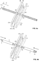
- An inventive room divider 1, 1 ' comprises vertical elements 2, 2', which are connected to one another via connecting elements 4, and which are fixed or fixed to one another via fixing elements 5 at a distance d. It is in the FIGS. 1 to 10b a first embodiment of a room divider 1 and in the FIGS. 11a to 11c a second embodiment of a room divider 1 'shown. The two embodiments differ essentially only in that the vertical elements 2 of the first embodiment have a rectangular configuration and the vertical elements 2 'of the second embodiment have a cylindrical configuration. It is thus to be understood that statements concerning the first embodiment apply analogously to the second embodiment and vice versa. For the sake of simplicity, the concrete construction and the mode of operation of the room divider will now be described with reference to the first embodiment according to FIGS FIGS. 1 to 10b explained.
- the room divider 1 comprises a plurality of Vertical elements 2 in the form of rectangular hollow sections, which each extend along a vertical direction V.
- the rectangular hollow profile has four side walls 21a, 21b, 21c, 21d, of which three are integrally formed with each other and which are connectable to the separately formed fourth side wall 21d. So that the joining of the vertical elements 2 can be better explained, the vertical elements 2 are in the FIGS. 4a to 4d each depicted without the fourth side wall 21d.
- the fourth side wall 21d can be attached after the connection of the vertical elements 2, or the fourth side wall 21d can already be attached during the connection of the vertical elements 2, respectively, or it is conceivable that all four side walls are integrally formed.
- the fourth side wall 21d on its inside facing the cavity 210 may at least partially 22 have a protruding structure, which jamming the fourth side wall 21d within the three side walls 21a, 21b, 21c and thus an attachment of the fourth side wall allows.
- the protruding structure has a width which corresponds approximately to the clear width of the U-profile formed by the three side walls 21a, 21b, 21c.
- each vertical element 2 has an inlet opening 23 and an outlet opening 24, through which a connecting element 4 extends in the form of a rope.
- a connecting element 4 extends in the form of a rope.
- the individual vertical elements 2 are connected to each other.
- it is advantageous for a stable connection of the vertical elements 2 if a plurality of inlet openings 23 and outlet openings 24 are present, through which in each case a connecting element 4 is guided.
- These two or more pairs of cooperating entrance and exit openings are then formed along the vertical direction V spaced from each other on the vertical element 2.
- an inlet and an outlet opening in the region of the upper end 28 of the vertical element and an inlet and an outlet opening in the region of the lower end 29 of the vertical element can be arranged, wherein the distance between the cooperating inlet and outlet openings to the upper end and to the lower End of the vertical element is the same or different.
- the or the connecting elements 4 thereby run along a direction perpendicular to the vertical direction V connecting direction C. If the vertical profiles 2 parallel to each other and are arranged within a common plane (see for example FIGS. 2a . 3a and 3b ), the connecting direction C coincides with a direction perpendicular to the vertical direction V horizontal direction H.
- the deformable design of the connecting element 4, in this case the property of the rope, to change its shape under the action of force, and as will be explained later, in particular also the deformable design of a fixing element 5 allows a variable alignment of the vertical profiles 2 to each other.
- the vertical elements 2 can be brought into the most different positions, so that the space divider 1 not only has a rectilinear shape (FIG. FIG. 2a ), but any shapes, such as a wavy ( FIG. 2b ), a rolled up ( Figure 2c ) or an arcuate ( Figure 2d ) Can take shape.
- a fastening element 25 can be arranged within the vertical elements 2, which here has the shape of a rectangular plate and extends with respect to the vertical direction V substantially along an entire length of the vertical elements 2.
- the fastening element 25 has one or more passage openings 26, through which the connecting element 4 is passed.
- the fastening element 25 has a single passage opening 26.
- the number of through holes 26 of the fasteners 25 ideally corresponds to the number of inlet and outlet openings 23, 24 of the vertical elements 2. It is also advantageous to arrange the fasteners 25 within the vertical elements 2 such that each of the inlet opening 23, the through hole 26 and the Outlet opening 24, through which the connecting element 4 is guided, are arranged on a common axis.
- the vertical elements 2 each have on their cavity facing inner sides 22a, 22b, 22c, 22d a connecting structure 27a, 27b, 27c, 27d in the form of a groove which extends along the vertical direction V extends.
- the clear width of the groove 27a, 27b, 27c, 27d corresponds approximately to the width of the fastening element 25, so that the fastening element 25 can be snapped into the groove and thereby fixed.
- To fasten the fastener 25 requires a groove in a side wall.
- the groove 27b is preferably in the connecting leg 21b of the vertical element 2 is arranged.
- the grooves 27a, 27c in the legs forming side walls 21a, 21c of the vertical element 2 are due to manufacturing reasons.
- the protruding structure (not shown) on the inner side 22d of the fourth side wall 21d also at least partially has a groove into which the fastening element can engage.
- the fourth side wall 21d may be fixed to the side walls 21a, 21c instead of by jamming, for example, and the groove 27d for receiving the fixing member 25 is then formed directly in the inside 22d of the fourth side wall 21d.
- the vertical elements 2 are connected to each other by means of the connecting element 4.
- the inlet openings 23 and the outlet openings 24 of the vertical elements 2 and the passage openings 26 of the fastening elements 25 each have a diameter dV or dB, which is larger than a diameter dS of the connecting element 4 seen in cross-section, see in particular FIG. 5a ,
- the connecting element 4 can extend completely with respect to the connecting direction C through the vertical elements 2 including the accommodated fastening elements 25.
- the vertical elements 2 are then mounted displaceably relative to one another with respect to the connecting direction C along the connecting element 4.
- the room divider 1 further comprises at least one fixing element 5, which extends along the connecting direction C through the inlet openings 23 and outlet openings 24 of the vertical elements 2 and, if present, through the through openings 26 of the fastening elements 25 ,
- the fixing element 5 in the present example is a hose which can be slipped over the connecting element 4. That is, the fixing element 5 forms a hollow body, wherein the connecting element 4 extends through the cavity 51 of the hollow body 5 therethrough.
- the fixing member 5 is also made of a deformable material, so that the room divider 1, the above can take different forms mentioned.
- it is advantageous to produce the fixing element 5 from a plastically deformable material so that the fixing element 5 can be bent by hand in a desired direction and then remains in this bent direction as long as no further force is applied in a different direction.
- a synthetic rubber with other properties such as, for example, a fixing element made of an elastomer such as chloroprene rubber (also known under the trade name Neoprene®).
- the fixing element 5 is designed such that, for example, a positive and / or non-positive connection with the vertical elements 2 takes place. If, for example, the fixing element 5 has a diameter dF, which is substantially equal to or larger than a diameter dV of the inlet openings 23 and outlet openings 24 of the vertical elements 2, the fixing element 5 can be arranged in the inlet openings 23 and outlet openings 24 of the vertical elements 2 are jammed, see for example FIG. 5b , In this case, it is not necessary to use a fastening element 25 for fixing the vertical elements 2. Instead, the vertical elements 2 are fixed solely due to the jamming with the fixing element 5 and thus prevented from shifting with respect to the connecting direction C.
- the vertical elements 2 can be fixed by means of the fixing element 5 and the fastening elements 25 at a distance from each other. If the passage openings 26 of the fastening elements 25 have a diameter dB, for example, which is essentially equal to or smaller than a diameter dF of the fixing element 5 in cross-section, then the fixing element 5 can be clamped in the passage openings 26 of the fastening elements 25. In particular, in the case where the diameter dB of the through-holes 26 of the fixing elements 25 is smaller than a diameter dF of the fixing element 5 in cross-section, the side surfaces 211 of two successive fixing elements 25 provide a specific stop for the fixing element 5.
- the lateral distance d between two adjacent vertical elements 2 can thus be adjusted or set in different, complementary or alternative ways. Namely, by jamming the vertical elements 2 on the fixing element 5 by means of the inlet openings 23 and outlet openings 24, by clamping the vertical elements 2 on the fixing element 5 by means of the through openings 26 of the fastening elements 25, and by providing a stop for the fixing element 5 by means of the fastening elements 25.
- the fixed lateral distance d between two adjacent vertical elements 2 depends thereby from the length of the fixing element 5 from. If a very short fixing element 5 is used, then the distance d between the vertical elements 2 is correspondingly small. Analogously, a very long fixing element 5 allows a large distance d between the vertical elements 2.
- the distance between two adjacent vertical elements is determined by the length of the fixing element connecting these two vertical elements.
- distance refers to the fixed distance between two adjacent fixing elements, in particular the distance between the inlet opening of the one vertical element and the outlet opening of the other vertical element or, if present, refers to the distance between the passage opening in the fastening element of the one vertical element and the passage opening in the fastening element of the other vertical element, along the fixing element. This distance or distance is the same for a straight-lined room divider as well as for a curved or otherwise deformed room divider.
- these fixing elements 5 can each have the same length or different lengths.
- the fixing elements 5 each have the same length and a fixation of the vertical elements 2 takes place, inter alia, by providing a stop by the fastening elements 25. For this reason, the lateral distances d between two successive vertical elements 2 are the same.
- a desired number of vertical elements 2 is provided.
- the vertical elements 2 by means of the connecting element 4, which is guided through the inlet and outlet openings 23, 24 of the vertical elements 2 and, if provided here, through the through holes 26 of the fastening elements 25, with each other.
- the vertical elements 2 are fixed with respect to the connecting direction C at a certain distance d from each other by means of the fixing element 5.
- 3a to 3c shown three vertical elements 2 present, the distance d between the first and the second vertical element 2 with a first fixing element 5, and the distance d between the second and the third vertical element 2 with a second fixing element 5 is fixed.
- These components are strung on a chain analogous to pearls. That is, first, the first vertical element 2 on the connecting element 4 and then the first fixing element 5 is lined up on the connecting element 4. In a next step, the second vertical element 2 is lined up on the connecting element 4 and then the second fixing element 5 on the connecting element 4. In yet another step, the third vertical element 2 and then a third fixing element 5 is lined up on the connecting element 4, and so on.
- any distances d between the adjacent vertical elements 2 can be further reduced by the vertical elements 2 are moved towards each other by means of the fixing elements 5 along the connecting direction C and along a direction opposite to the connecting direction. This is by means of the two arrows in FIG. 3b indicated.
- the fixing elements 5 slide along the connecting element 4 mounted in them until the free ends 212 of the fixing elements 5 abut against the side surfaces 211 of the fastening elements 25. Then, the room divider 1 can be bent by hand into a desired shape.
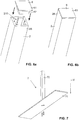
- the vertical elements 2 are hollow profiles. How out Figures 6a and 6b As can be seen, they can have open upper and lower open ends 28, 29, which can be closed by a retractable cover 6.
- the cover 6 comprises an outer part 61 and an inner part 62, wherein the diameter of the outer part approximately corresponds to the outer diameter of the hollow body 2 and the diameter of the inner part 62 approximately to the diameter of the cavity 210.
- the outer part 61 of the cover 6 closes the free end of the Vertical element 2 flush, wherein the inner part 62 jammed in the cavity 210 and the lid 6 is thereby secured to the vertical element 2.
- a sealing element 64 is used as a rubber ring (see FIG. 10a ).
- This sealing element 64 allows a better jamming of the lid 6, whereby a possible sticking or screwing the lid is obsolete.
- the cover 6 are then releasably attached to the vertical elements 2 and can be easily removed if necessary, for example, if, as will be explained in more detail below, a footrest 7 is to be attached to the room divider.
- the room divider 1 may have one or more foot rests 7, which are respectively arranged at the lower ends 29 of the vertical elements 2 and give stability to the room divider.
- the footrest 7 has a base plate 71 for resting on a floor and a vertically projecting from the base plate 71 structure 72 for connection to a vertical element 2.
- the projecting structure is a substantially rectangular pillar 72, which through the lower open end 29 of the vertical element 2 can be inserted into the cavity 210 of the vertical element 2.
- the projecting structure 72 and the base plate 71 are separate components which are bolted together. Another possibility would be to provide the base plate 71 with the projecting structure 72 as a single part.
- the base plate 71 may consist of two or more sub-panels which are piled up. A particularly good stabilization of the vertical elements 2 is achieved when one or more of the arranged in the region of the vertical elements 2 lower plates have a recess into which the lower end 29 of the vertical elements 2 can be received respectively.
- the base plate 71 may consist only of a plate which has such a recess or cover 6 are inserted into the lower open ends 29, which has a thickness corresponding to the thickness of Have base plate (see, eg FIG. 10a ).
- the footrests 7 can be used to set a desired distance between the lower ends 29 of the vertical elements 2 and the bottom, not shown here.
- spacers can be used, which are first attached to the projecting structure 72 of the footrest 7, and on which spacers then the vertical elements 2 when connecting with the projecting structures 72 rest.
- the spacers are preferably likewise hollow bodies whose cross section can be formed analogously to the cross section of the vertical elements 2. For example, therefore, rectangular or cylindrical hollow body, wherein the projecting structure 72 is guided through the cavity of the spacers.
- the room divider 1 is terminated at its outer ends in each case with a closing element 3. That is, the room divider 1 comprises two end elements 3, between which the vertical elements 2 are arranged. These end elements 3 are in the FIGS. 8a to 9c illustrated and correspond to elongate elements which extend along the vertical direction V and which each have at least one inlet opening 31.
- the connecting element 4 is pulled along the connecting direction C through the inlet opening 31 of the second terminating element 3 or along a direction opposite the connecting direction C through the inlet opening 31 of the first terminating element 3.
- the connecting element 4 is then fastened via fastening means 33 such as screws to the end elements 3.
- an indentation 34 can be formed in each case on an outer side of the end elements 3, in which the free end 41 of the connecting element 4 together with the fastening means 33 is received.
- a fastening element 35 with at least one passage opening 36 can be arranged on the end elements 3, with the connecting element 4 extending through the passage openings 36 of the fastening elements 35.
- the fastening element 35 is formed as a rectangular plate, which extends with respect to the vertical direction V along the entire length of the closing element 3.
- the end elements 3 and the associated fastening elements 35 can each be formed in one piece or separately formed components.
- the closing element 3 and the fastening element 35 are integrally formed.
- the distance d between the end elements 3 and the vertical elements 2 adjacent to these end elements 3 is likewise fixed to the fixing elements 5 as described above.
- the fastening elements 35 of the end elements 3 have passage openings 36 analogous to the passage openings 26 of the fastening elements 25 of the vertical elements 2, wherein the passage openings 36 of the fastening elements 35 of the end elements 3 each have a diameter dA, which is substantially equal to or smaller than a Diameter dF of the fixing element 5 is seen in cross section.
- the through openings 36 of the fastening elements 35 and the inlet openings 31 of the closing elements 3 form a single through opening through the fastening elements and the end elements, wherein this through opening opens into the recess 34.
- the distances d between the vertical elements 2 and the end elements 3 is thus also by clamping the end elements 3 on the fixing element 5 by means of the inlet openings 31 of the end elements 3, by clamping the end elements 3 on the fixing element 5 by means of the through holes 36 of the fastening elements 35 of the end elements. 3 respectively set by providing a stop for the fixing element 5 by means of the side surfaces of the fastening elements 25, 35.
- cover members 37 are attached to the end elements 3, which cover this attachment.
- the cover element 37 is a substantially U-shaped profile, in which the end elements 3 are at least partially received.
- the end elements 3 with the attached respectively integral fasteners 35 to the cross-section substantially T-shaped, wherein the dimensions of the longitudinal ridge of the "T", ie the end member 3, a locking or jamming of the end member 3 in the U-shaped Allow profile of the cover 37.
- the crosspiece of the "T" that is, the fastening element 35
- the fastening means 33 for the connecting means 4 are completely covered by the cover 37.
- the end elements 3, or even only the end elements 3 are connected to footrests 7 as described above.
- the end elements have open lower ends 311 into which the protruding structure 72 of the support leg can be inserted.
- the open ends are in each case formed by the fastening element 35 and the cover element 37, which have a length with respect to the vertical direction, which are greater than a length of the end elements 3 in the region of their inlet openings 31.
- the length of the longitudinal ridge of the "T" is smaller than the length of the crosspiece of the "T” and smaller than the length of the cover members 37 along the vertical direction.
- the fastening elements 35 and the cover elements again form a hollow profile with a cavity 312 into which the projecting structure of the support foot can be inserted (see in particular FIG. 10a ).
- the end elements with open upper ends, which can then be closed with a lid 6 analogously to the vertical elements.
- the vertical elements 2 and, of course, the end elements 3 can not only have the previously discussed rectangular shape but any shapes.
- these elements may be cylindrical, as in the FIGS. 11a to 11c is shown.
- the vertical elements 2, the end elements 3 and the cover 37 are made of wood. Conceivable, however, are many other materials such as plastic or metal.
- the footrest 7 can be made of a variety of materials, with good stability is achieved in particular with footrests made of metal. LIST OF REFERENCE NUMBERS 1, 1 ' room divider 41 free end 2, 2 ' vertical element 5 fixing 21a, ... Side wall 51 cavity 22a, ...
Landscapes
- Engineering & Computer Science (AREA)
- Architecture (AREA)
- Physics & Mathematics (AREA)
- Electromagnetism (AREA)
- Civil Engineering (AREA)
- Structural Engineering (AREA)
- Connection Of Plates (AREA)
Abstract
Ein Raumteiler (1) umfasst mindestens zwei Vertikalelemente (2) mit jeweils mindestens einer Eintrittsöffnung (23) und mindestens einer Austrittsöffnung (24), und mindestens ein Verbindungselement (4), welches sich entlang einer Verbindungsichtung (C) durch die Eintrittsöffnungen (23) und Austrittsöffnungen (24) hindurcherstreckt, wodurch die Vertikalelemente (2) miteinander verbunden werden. Der Raumteiler (1) umfasst weiter mindestens ein Fixierelement (5), welches sich entlang der Verbindungsrichtung (C) durch die Eintrittsöffnung (23) des einen Vertikalelements (2) sowie durch die Austrittsöffnung (24) des anderen Vertikalelements (2) erstreckt, und welches Fixierelement (5) dabei derart ausgebildet ist, dass die Vertikalelemente (2) bezüglich der Verbindungsrichtung (C) in einem Abstand (d) zueinander festgelegt werden.A room divider (1) comprises at least two vertical elements (2) each having at least one inlet opening (23) and at least one outlet opening (24), and at least one connecting element (4) extending along a connection direction (C) through the inlet openings (23). and outlet openings (24) extends therethrough, whereby the vertical elements (2) are interconnected. The room divider (1) further comprises at least one fixing element (5), which extends along the connecting direction (C) through the inlet opening (23) of the one vertical element (2) and through the outlet opening (24) of the other vertical element (2), and which fixing element (5) is designed such that the vertical elements (2) with respect to the connecting direction (C) at a distance (d) are fixed to each other.
Description
Die vorliegende Erfindung betrifft einen Raumteiler gemäss Anspruch 1 und ein Verfahren zur Herstellung eines solchen Raumteilers gemäss Anspruch 15.The present invention relates to a room divider according to
Raumteiler sind in den unterschiedlichsten Ausführungsformen und aus den verschiedensten Materialien bekannt. Beispielsweise existieren Raumteiler mit fest eingebauten Trennflächen oder Lamellen oder solche, deren Trennflächen oder Lamellen je nach Bedarf verändert werden können. Aus
Ein Raumteiler sollte eine möglichst einfache und optisch ansprechende Konstruktion aufweisen, eine leichte Handhabung zulassen und an die individuellen Bedürfnisse eines Benutzers anpassbar sein. Die bisher bekannten Raumteiler erfüllen diese Anforderungen jedoch nur teilweise.A room divider should have a simple and visually appealing construction, allow easy handling and be adaptable to the individual needs of a user. However, the previously known room divider fulfill these requirements only partially.
Es ist daher eine Aufgabe der vorliegenden Erfindung, einen verbesserten Raumteiler anzugeben. Insbesondere ist es eine Aufgabe, einen Raumteiler anzugeben, welcher eine einfache und dennoch zuverlässige Konstruktion aufweist und über eine leichte Handhabung verfügt.It is therefore an object of the present invention to provide an improved room divider. In particular, it is an object to provide a room divider which has a simple yet reliable construction and has easy handling.
Diese Aufgabe wird gelöst durch einen Raumteiler gemäss Anspruch 1. Ein solcher Raumteiler umfasst mindestens zwei Vertikalelemente, welche sich jeweils entlang einer vertikalen Richtung erstrecken und welche jeweils mindestens eine Eintrittsöffnung und mindestens eine Austrittsöffnung aufweisen, und mindestens ein Verbindungselement, welches sich entlang einer senkrecht zur vertikalen Richtung verlaufenden Verbindungsichtung durch die Eintrittsöffnungen und Austrittsöffnungen der Vertikalelemente hindurcherstreckt, wodurch die Vertikalelemente mittels des Verbindungselements miteinander verbunden werden. Der Raumteiler umfasst weiter mindestens ein Fixierelement, welches sich entlang der Verbindungsrichtung durch die Eintrittsöffnung des einen Vertikalelements sowie durch die Austrittsöffnung des anderen Vertikalelements erstreckt, und welches Fixierelement dabei derart ausgebildet ist, dass die Vertikalelemente bezüglich der Verbindungsrichtung in einem Abstand zueinander festgelegt werden.This object is achieved by a room divider according to
Das heisst, der erfindungsgemässe Raumteiler umfasst zwei oder mehr Vertikalelemente, welche über ein oder mehrere Verbindungselemente miteinander verbunden werden, und welche über ein oder mehrere Fixierelemente in einem bestimmten Abstand zueinander festgelegt beziehungsweise fixiert werden. Das oder die Fixierelemente verhindern also ein Verschieben der Vertikalelemente entlang der Verbindungsrichtung. Dadurch, dass sich das bzw. die Fixierelemente dabei durch die Eintrittsöffnungen und Austrittsöffnungen der Vertikalelemente erstrecken, und beispielsweise nicht nur zwischen den Vertikalelementen ausgebildet sind, wird eine gute Fixierung der Vertikalelemente gewährleistet. Gleichzeitig werden keine von aussen sichtbare Befestigungsmittel wie Schrauben, Scharniere oder dergleichen zur Festlegung respektive Fixierung der Vertikalelemente benötigt, was die Herstellung des Raumteilers vereinfacht und dem Raumteiler eine optisch ansprechende Ausgestaltung verleiht.That is, the inventive room divider comprises two or more vertical elements, which are connected to one another via one or more connecting elements, and which are fixed or fixed to one another via one or more fixing elements at a certain distance. The one or more fixing elements thus prevent a displacement of the vertical elements along the connecting direction. The fact that the fixing element or elements thereby extend through the inlet openings and outlet openings of the vertical elements, and for example, are not only formed between the vertical elements, a good fixation of the vertical elements is ensured. At the same time no externally visible fastening means such as screws, hinges or the like for fixing respectively fixing the vertical elements are needed, which simplifies the production of the room divider and gives the room divider a visually appealing design.
Das Fixierelement und die Vertikalelemente können formschlüssig und/oder kraftschlüssig miteinander verbunden sein. So kann das Fixierelement im Querschnitt gesehen einen Durchmesser aufweisen, welcher im Wesentlichen gleich gross oder grösser als ein Durchmesser der Eintrittsöffnungen und Austrittsöffnungen der Vertikalelemente ist. Dies bewirkt, dass das Fixierelement in den Eintrittsöffnungen und den Austrittsöffnungen der Vertikalelemente verklemmt wird. Dadurch werden die Vertikalelemente am Verschieben gehindert. Eine besonders gute Verklemmung des Fixierelements wird erreicht, wenn der Durchmesser der Eintrittsöffnungen und Austrittsöffnungen der Vertikalelemente kleiner als der Durchmesser des Fixierelements im Querschnitt gesehen ist. Es ist jedoch auch denkbar, dass das Fixierelement im Querschnitt einen kleineren Durchmesser aufweist als die Eintrittsöffnungen und Austrittsöffnungen der Vertikalelemente. In diesem Fall kann das Fixierelement durch diese Öffnungen hindurchgeführt werden, ohne dass die Vertikalelemente verklemmt werden. Ein Verschieben der Vertikalelemente wird dann anderweitig verhindert, wie nun erläutert wird.The fixing element and the vertical elements can be positively and / or non-positively connected to each other. Thus, the fixing element seen in cross-section may have a diameter which is substantially equal to or greater than a diameter of the inlet openings and outlet openings of the vertical elements. This causes the fixing element is clamped in the inlet openings and the outlet openings of the vertical elements. As a result, the vertical elements are prevented from moving. A particularly good clamping of the fixing element is achieved if the diameter of the inlet openings and outlet openings of the vertical elements is smaller than the diameter of the fixing element seen in cross section. However, it is also conceivable that the fixing element in cross section has a smaller diameter than the inlet openings and outlet openings of the vertical elements. In this case, the fixing element can be passed through these openings without jamming the vertical elements. A displacement of the vertical elements is then otherwise prevented, as will now be explained.
So kann jeweils ein Befestigungselement mit mindestens einer Durchgangsöffnung im Vertikalelement angeordnet sein, wobei sich das Verbindungselement durch die Durchgangsöffnungen der Befestigungselemente hindurcherstreckt, und wobei die Durchgangsöffnungen der Befestigungselemente jeweils einen Durchmesser aufweisen, welcher im Wesentlichen gleich gross oder kleiner als ein Durchmesser des Fixierelements im Querschnitt gesehen ist. Hierbei ermöglicht das Befestigungselement ein Verklemmen des Fixierelements in dessen Durchgangsöffnung, wodurch die Vertikalelemente mittels des Befestigungselements fixiert respektive festgelegt werden. Auch hier ist eine Verklemmung insbesondere dann stark, wenn der Durchmesser der Durchgangsöffnungen kleiner als der Durchmesser des Fixierelements im Querschnitt gesehen ist. Allerdings kann eine Fixierung der Vertikalelemente nicht nur durch eine Verklemmung erfolgen. Alternativ oder zusätzlich dazu können die Befestigungselemente derart ausgebildet und angeordnet sein, dass die Befestigungselemente von jeweils zwei benachbarten Vertikalelementen einen Anschlag für das zwischen diesen zwei Vertikalelementen angeordnete Fixierelement bereitstellen. Beim Befestigungselement handelt es sich vorzugsweise um ein Element mit einer länglichen Struktur wie eine im Wesentlichen rechteckige Platte, welche sich zumindest teilweise entlang der vertikalen Richtung erstreckt. Indem nun benachbarte Vertikalelemente solch ein Element aufweisen, welches bezüglich der Verbindungsrichtung zumindest im Bereich der Eintritts- und Austrittsöffnungen der Vertikalelemente angeordnet ist, trifft das Fixierelement beim Durchführen durch das Vertikalelement auf dieses Element auf. Sofern das Befestigungselement an der Auftreffstelle keine Durchgangsöffnung aufweist, deren Durchmesser genügend gross ist, so dass das Fixierelement reibungslos oder widerstandslos hindurchgeführt werden kann, so wird das Fixierelement an dieser Stelle durch das Befestigungselement blockiert. Oder anders gesagt, dass Fixierelement schlägt am Befestigungselement an.Thus, in each case a fastening element can be arranged with at least one passage opening in the vertical element, wherein the connecting element extends through the passage openings of the fastening elements, and wherein the through openings of the fastening elements each have a diameter which is substantially equal to or smaller than a diameter of the fixing element in cross section is seen. In this case, the fastening element allows a jamming of the fixing element in its passage opening, whereby the vertical elements are fixed by means of the fastening element or fixed. Again, a deadlock is particularly strong when the diameter of the through holes is smaller than the diameter of the fixing seen in cross section. However, a fixation of the vertical elements can not be done only by jamming. Alternatively or additionally, the fastening elements may be designed and arranged such that the fastening elements of each two adjacent vertical elements provide a stop for the fixing element arranged between these two vertical elements. The fastener is preferably an element having an elongate structure such as a substantially rectangular plate extending at least partially along the vertical direction extends. By now adjacent vertical elements having such an element, which is arranged with respect to the connecting direction at least in the region of the inlet and outlet openings of the vertical elements, the fixing element encounters when passing through the vertical element on this element. If the fastening element at the place of impact has no passage opening, whose diameter is sufficiently large, so that the fixing element can be passed smoothly or without resistance, the fixing element is blocked at this point by the fastening element. In other words, the fixing element abuts on the fastening element.
Sofern das Fixierelement durch die Durchgangsöffnungen hindurchgeführt werden kann, so ist das Bereitstellen von einem einzigen Fixierelement für das Festlegen der Vertikalelemente im Prinzip ausreichend. Sofern das Fixierelement an den Befestigungselementen anschlägt, so ist jeweils ein Fixierelement für zwei aufeinanderfolgende Vertikalelemente vorzusehen. Natürlich können auch im ersten Fall mehrere Fixierelemente vorgesehen sein, wobei jeweils ein Fixierelement zwei oder mehr aufeinanderfolgende Vertikalelemente in ihrem Abstand zueinander fixiert.If the fixing element can be passed through the passage openings, the provision of a single fixing element for fixing the vertical elements is sufficient in principle. If the fixing element abuts against the fastening elements, then a fixing element for two successive vertical elements is to be provided in each case. Of course, a plurality of fixing elements can also be provided in the first case, with one fixing element each fixing two or more successive vertical elements in their mutual spacing.
Damit das Verbindungselement gut durch die Vertikalelemente hindurchgeführt werden kann ist es von Vorteil, wenn die Eintrittsöffnungen und die Austrittsöffnungen der Vertikalelemente jeweils einen Durchmesser aufweisen, welcher grösser als ein Durchmesser des Verbindungselements im Querschnitt gesehen ist. Analoges gilt für den Fall, dass die Vertikalelemente Befestigungselemente aufweisen, wobei es dann von Vorteil ist, wenn die Durchgangsöffnungen der Befestigungselemente einen Durchmesser aufweisen, welcher grösser als der Durchmesser des Verbindungselements im Querschnitt gesehen ist. Nebst einer einfachen Verbindung der Vertikalelemente miteinander ermöglicht diese Ausgestaltung zudem, dass die Ausrichtung der Vertikalelemente zueinander geändert werden kann. Dies wird später eingehender erläutert.So that the connecting element can be passed well through the vertical elements, it is advantageous if the inlet openings and the outlet openings of the vertical elements each have a diameter which is larger than a diameter of the connecting element seen in cross section. The same applies to the case in which the vertical elements have fastening elements, wherein it is advantageous if the through openings of the fastening elements have a diameter which is larger than the diameter of the connecting element seen in cross section. In addition to a simple connection of the vertical elements with each other, this embodiment also allows the orientation of the vertical elements to each other can be changed. This will be explained later in more detail.
Die Vertikalelemente sind vorzugsweise jeweils als Hohlkörper ausgebildet und weisen einen Hohlraum auf, wobei die Befestigungselemente jeweils innerhalb dieses Hohlraums angeordnet sind. Dabei sind jegliche länglich ausgebildeten Strukturen denkbar, wobei auf dem Gebiet typische Strukturen Hohlzylinder oder rechteckige Hohlprofile sind.The vertical elements are preferably each formed as a hollow body and have a cavity, wherein the fastening elements are each disposed within this cavity. In this case, any elongated structures are conceivable, typical structures in the field being hollow cylinders or rectangular hollow profiles.
Die Vertikalelemente können jeweils eine Innenseite mit mindestens einer Verbindungsstruktur, insbesondere einer Nut, aufweisen, wobei die Befestigungselemente über die Verbindungsstruktur im Hohlraum der Vertikalelemente befestigbar sind.The vertical elements can each have an inner side with at least one connecting structure, in particular a groove, wherein the fastening elements can be fastened via the connecting structure in the cavity of the vertical elements.
Die Verbindungsstruktur erstreckt sich vorzugsweise zumindest teilweise entlang der vertikalen Richtung. Wird die Verbindungsstruktur in Form einer Nut bereitgestellt, so ist es von Vorteil, wenn das Befestigungselement mit der Nut eine Rastverbindung eingehen kann. Andere Verbindungsarten sind jedoch genauso denkbar. Zum Beispiel kann das Befestigungselement auf die Innenseite der Vertikalelemente aufgeklebt werden.The connection structure preferably extends at least partially along the vertical direction. If the connection structure is provided in the form of a groove, then it is advantageous if the fastening element can make a latching connection with the groove. However, other types of connection are equally conceivable. For example, the fastener may be adhered to the inside of the vertical members.
Vorzugsweise sind das Fixierelement und/oder das Verbindungselement verformbar ausgebildet. Besonders bevorzugt sind das Fixierelement und/oder das Verbindungselement plastisch verformbar ausgebildet. Es ist jedoch auch denkbar, eines oder beide dieser Komponenten aus einem biegschlaffen Material bereitzustellen. Beispielsweise kann das Verbindungselement in Form eines Seils und/oder das Fixierelement in Form eines plastisch verformbaren Kunststoffs beziehungsweise eines synthetischen Polymers zur Verfügung gestellt werden.Preferably, the fixing element and / or the connecting element are deformable. Particularly preferably, the fixing element and / or the connecting element are formed plastically deformable. However, it is also conceivable to provide one or both of these components from a flexible material. For example, the connecting element in the form of a rope and / or the fixing element in the form of a plastically deformable plastic or a synthetic polymer can be provided.
Die verformbare Ausgestaltung des Verbindungselements und/oder des Fixierelements erlaubt eine variable Ausrichtung der Vertikalprofile zueinander. Beispielsweise kann eine manuelle Kraft auf die durch das Fixierelement festgelegten Vertikalelemente ausgeübt werden, wobei die Vertikalelemente in eine gewünschte Position verschoben oder versetzt werden. Solange keine weitere Krafteinwirkung in eine andere Richtung erfolgt, so verbleiben die Vertikalelemente in ihrer versetzten Position. Der Raumteiler kann also unterschiedliche geometrische Ausgestaltungen einnehmen wie z.B. eine gerade oder gebogene Form, und alsdann in dieser Ausgestaltung verbleiben.The deformable design of the connecting element and / or the fixing element allows a variable orientation of the vertical profiles to each other. For example, a manual force can be exerted on the vertical elements defined by the fixing element, wherein the vertical elements are displaced or displaced to a desired position. As long as no further force is applied in a different direction, the vertical elements remain in their staggered position. The partition can thus take different geometric configurations such. a straight or curved shape, and then remain in this embodiment.
Das Fixierelement kann ein Hohlkörper, insbesondere ein Hohlzylinder, mit einem Hohlraum sein, wobei sich das Verbindungselement durch den Hohlraum des Fixierelements hindurch erstreckt. Das heisst, das Fixierelement bildet einen Hohlkörper, wobei sich das Verbindungselement durch den Hohlraum des Hohlkörpers hindurch erstreckt. Indem der Durchmesser des Fixierelements im Querschnitt gesehen grösser gewählt wird als der Durchmesser des Verbindungselements im Querschnitt gesehen, ist das Fixierelement auf dem Verbindungselement verschiebbar gelagert.The fixing element may be a hollow body, in particular a hollow cylinder, with a cavity, wherein the connecting element extends through the cavity of the fixing element. That is, the fixing element forms a hollow body, wherein the connecting element extends through the hollow space of the hollow body. By the diameter of the fixing seen in cross section larger is selected as the diameter of the connecting element seen in cross-section, the fixing element is slidably mounted on the connecting element.
Der Raumteiler kann weiter zwei Abschlusselemente umfassen, welche sich jeweils entlang der vertikalen Richtung erstrecken und welche jeweils mindestens eine Eintrittsöffnung und mindestens eine Austrittsöffnung aufweisen, wobei die Vertikalelemente bezüglich der Verbindungsrichtung zwischen den Abschlusselementen angeordnet sind, wobei sich das Verbindungselement entlang der Verbindungsrichtung durch die Eintrittsöffnungen und Austrittsöffnungen der Abschlusselemente hindurcherstreckt, wodurch die Abschlusselemente mit den Vertikalelementen verbunden werden, und wobei das Verbindungselement insbesondere über Befestigungsmittel an den Abschlusselementen befestigt ist.The room divider may further comprise two end elements each extending along the vertical direction and each having at least one entrance opening and at least one exit opening, the vertical elements being arranged with respect to the connection direction between the end elements, the connection element extending along the direction of connection through the entry openings and exit openings of the terminating elements extends therethrough, whereby the terminating elements are connected to the vertical elements, and wherein the connecting element is fastened in particular via fastening means on the end elements.
Oder anders gesagt ist es denkbar, in Bezug auf die Verbindungsrichtung das erste Vertikalelement und das letzte Vertikalelement jeweils mit einem Abschlusselement zu verbinden.In other words, it is conceivable to connect the first vertical element and the last vertical element respectively to a terminating element in relation to the connecting direction.
Jeweils ein Befestigungselement mit mindestens einer Durchgangsöffnung kann am Abschlusselement angeordnet sein, wobei sich das Verbindungselement durch die Durchgangsöffnung des Befestigungselements hindurcherstreckt, und wobei die Durchgangsöffnung des Befestigungselements jeweils einen Durchmesser aufweist, welcher im Wesentlichen gleich gross oder kleiner als ein Durchmesser des Fixierelements im Querschnitt gesehen ist.In each case a fastening element with at least one passage opening can be arranged on the closing element, wherein the connecting element extends through the through opening of the fastening element, and wherein the through opening of the fastening element in each case has a diameter which is substantially equal to or smaller than a diameter of the fixing element seen in cross section is.
Eine Verbindung beziehungsweise Festlegung der Vertikalelemente mit den Abschlusselementen kann somit analog zu der Verbindung beziehungsweise Festlegung der Vertikalelemente untereinander erfolgen. Das heisst, auch die Abschlusselemente können über Befestigungselemente mit Durchgangsöffnungen verfügen, die das Festlegen des ersten respektive letzten Vertikalelements in einem Abstand zum jeweiligen benachbarten Abschlusselement erlauben. Auch ist es dabei denkbar, dass das Fixierelement formschlüssig und/oder kraftschlüssig mit den Befestigungselementen der Abschlusselemente verbindbar ist, beispielsweise indem das Fixierelement aufgrund seines grösseren Durchmessers in den Durchgangsöffnungen der Befestigungselemente verklemmt wird. Ebenfalls ist es denkbar, dass die Befestigungselemente der Abschlusselemente und die mit den Abschlusselementen verbundenen Vertikalelemente einen Anschlag für das zwischen ihnen angeordnete Fixierelement bereitstellen.A connection or definition of the vertical elements with the end elements can thus be carried out analogously to the connection or determination of the vertical elements with each other. This means that the terminating elements may also have fastening elements with passage openings which allow the fixing of the first or last vertical element at a distance from the respective adjacent terminating element. It is also conceivable that the fixing element is positively and / or non-positively connected to the fastening elements of the end elements, for example by the fixing due to its larger diameter in the through holes of the fasteners is jammed. It is also conceivable that the fastening elements of the end elements and the vertical elements connected to the end elements provide a stop for the fixing element arranged between them.
Für eine besonders ästhetische Wahrnehmung des Raumteilers ist es von Vorteil, wenn die Befestigung des Verbindungselements an den Abschlusselementen für einen Betrachter des Raumteilers verborgen bleibt. So ist es denkbar, dass der Raumteiler zwei Abdeckelemente umfasst, wobei jeweils ein Abdeckelement an einem der Abschlusselemente derart befestigt ist, dass die Befestigung des Verbindungselements am Abschlusselement von aussen nicht sichtbar ist. Beispielsweise kann es sich bei den Abdeckelementen um Profilstrukturen handeln, in welche die Abdeckelemente zumindest teilweise aufnehmbar sind, wobei die Abschlusselemente zumindest im Bereich der Befestigung des Verbindungselements innerhalb der Profilstruktur zu liegen kommen. Das freie Ende des Verbindungselements und dessen Befestigung am Abschlusselement ist dadurch nicht mehr sichtbar, wodurch der Raumteiler optisch besonders ansprechend wirkt. Bevorzugt erstreckt sich das Abdeckelement in der vertikalen Richtung entlang der gesamten Länge des Abschlusselements und bedeckt die einem Betrachter zugewandten Seiten des Abschlusselements vollständig.For a particularly aesthetic perception of the room divider, it is advantageous if the attachment of the connecting element to the end elements for a viewer of the room divider remains hidden. Thus, it is conceivable that the room divider comprises two cover elements, wherein in each case a cover is attached to one of the end elements such that the attachment of the connecting element on the end element from the outside is not visible. For example, the cover elements can be profile structures in which the cover elements can be accommodated at least partially, the end elements coming to rest within the profile structure at least in the region of the attachment of the connection element. The free end of the connecting element and its attachment to the closing element is thus no longer visible, whereby the room divider looks visually appealing. Preferably, the cover member extends in the vertical direction along the entire length of the end member and completely covers the observer-facing sides of the end member.
Mindestens eines der Vertikalelemente und/oder mindestens eines der Abschlusselemente kann jeweils über ein offenes oberes Ende und/oder über ein offenes unteres Ende verfügen, wobei das obere offene Ende beziehungsweise das untere offene Ende durch einen einschiebbaren Deckel geschlossen ist.At least one of the vertical elements and / or at least one of the end elements can each have an open upper end and / or an open lower end, wherein the upper open end and the lower open end is closed by a retractable lid.
Bei Vertikalelementen in Form von Hohlprofilen, zum Beispiel, kann es wiederum aus ästhetischen Gründen wünschenswert sein, offene Bereiche der Hohlprofile wie die offenen Enden zu verschliessen. Anstelle eines einschiebbaren Deckels sind allerdings auch andere Verbindungen des Deckels wie Verkleben oder Verschrauben möglich. Zudem ist es möglich, die Vertikalelemente mit geschlossenen Enden bereitzustellen, so dass das Bereitstellen eines Deckels entfällt.For example, in the case of vertical elements in the form of hollow sections, it may be desirable for aesthetic reasons to close open areas of the hollow sections such as the open ends. Instead of a retractable lid, however, other connections of the lid are possible such as gluing or screwing. In addition, it is possible to provide the vertical elements with closed ends, so that the provision of a lid is eliminated.
Der Raumteiler kann weiter mindestens eine Fussstütze umfassen, welche an einem unteren Ende des Vertikalelements und/oder des Abschlusselements angeordnet ist. Die Fussstützen dienen dazu, den Raumteiler auf einem Boden abzustützen und diesem Stabilität zu verleihen.The room divider may further comprise at least one footrest, which is arranged at a lower end of the vertical element and / or the closing element. The Footrests serve to support the room divider on a floor and to give it stability.
Die Vertikalelemente und/oder die Abschlusselemente können im Wesentlichen zylindrisch oder rechteckig und vorzugsweise aus Holz ausgebildet sein. Andere Materialien wie Kunststoff oder Metall sind jedoch genauso denkbar und können auf den Kundenwunsch abgestimmt werden. Analoges gilt auch für die Fussstützen, welche zum Beispiel aus Metall, aber auch aus anderen tragfähigen Materialien bestehen können.The vertical elements and / or the end elements may be substantially cylindrical or rectangular and preferably formed of wood. However, other materials such as plastic or metal are equally conceivable and can be tailored to the customer's request. The same applies to the footrests, which may for example consist of metal, but also of other viable materials.
Ein Verfahren zur Herstellung eines Raumteilers wie oben beschrieben umfasst die Schritte von:
- Bereitstellen der mindestens zwei Vertikalelemente;
- Verbinden der Vertikalelemente mittels des mindestens einen Verbindungselements; und
- Festlegen der Vertikalelemente bezüglich der Verbindungsrichtung in einem Abstand zueinander mittels des Fixierelements.
- Providing the at least two vertical elements;
- Connecting the vertical elements by means of the at least one connecting element; and
- Fixing the vertical elements with respect to the connecting direction at a distance from each other by means of the fixing element.
Bevorzugte Ausführungsformen der Erfindung werden im Folgenden anhand der Zeichnungen beschrieben, die lediglich zur Erläuterung dienen und nicht einschränkend auszulegen sind. In den Zeichnungen zeigen:
- Fig. 1
- zeigt eine perspektivische Ansicht eines Raumteilers gemäss einer ersten Ausführungsform umfassend Vertikalelemente und Stützfüsse;
- Fig. 2a
- zeigt eine schematische Draufsicht auf einen Raumteiler gemäss
Figur 1 in einer ersten Position; - Fig. 2b
- zeigt eine schematische Draufsicht auf den
Raumteiler gemäss Figur 1 in einer zweiten Position; - Fig. 2c
- zeigt eine schematische Draufsicht auf den
Raumteiler gemäss Figur 1 ohne Stützfüsse in einer dritten Position; - Fig. 2d
- zeigt eine schematische Draufsicht auf den
Raumteiler gemäss Figur 1 in einer vierten Position; - Fig. 3a
- zeigt einen Ausschnitt des Raumteilers gemäss der ersten Ausführungsform mit nicht festgelegten Vertikalelementen;
- Fig. 3b
- zeigt einen Ausschnitt des Raumteilers gemäss der ersten Ausführungsform mit festgelegten Vertikalelementen in der ersten Position;
- Fig. 3c
- zeigt einen Ausschnitt des Raumteilers gemäss der ersten Ausführungsform mit festgelegten Vertikalelementen in der zweiten und vierten Position;
- Fig. 4a
- zeigt eine perspektivische Ansicht eines Vertikalelements mit eingefügtem Verbindungselement;
- Fig. 4b
- zeigt eine perspektivische Ansicht des Vertikalelements gemäss
Figur 4a mit Fixierelement in einem ersten Zustand; - Fig. 4c
- zeigt eine perspektivische Ansicht des Vertikalelements gemäss
Figur 4a mit Fixierelement in einem zweiten Zustand; - Fig. 4d
- zeigt eine perspektivische Ansicht des Vertikalelements gemäss
Figur 4a mit einem weiteren Vertikalelement und weiteren Fixierelementen; - Fig. 5a
- zeigt einen bereichsweisen zentralen Längsschnitt durch ein Vertikalelement mit Verbindungselement;
- Fig. 5b
- zeigt einen bereichsweisen zentralen Längsschnitt durch ein Vertikalelement mit Verbindungselement und Fixierelement;
- Fig. 6a
- zeigt eine perspektivische Ansicht eines Vertikalelements und eines Deckels in unverschlossenem Zustand;
- Fig. 6b
- zeigt eine perspektivische Ansicht des Vertikalelements und des Deckels gemäss
Figur 6a in verschlossenem Zustand; - Fig. 7
- zeigt eine perspektivische Ansicht einer Fussstütze;
- Fig. 8a
- zeigt eine Schnittansicht eines Abschlusselements und eines Abdeckelements in unverbundenem Zustand;
- Fig. 8b
- zeigt eine Schnittansicht des Abschlusselements und des Abdeckelements gemäss
Figur 8a in verbundenem Zustand; - Fig. 9a
- zeigt eine weitere Schnittansicht eines Abschlusselements und Abdeckelements in unverbundenem Zustand;
- Fig. 9b
- zeigt eine Schnittansicht des Abschlusselements und Abdeckelements gemäss
Figur 9a in verbundenem Zustand mit eingeführtem Verbindungselement; - Fig. 9c
- zeigt eine Schnittansicht des Abschlusselements, Abdeckelements und Verbindungselements gemäss
Figur 9b mit eingeführtem Fixierelement; - Fig. 10a
- zeigt eine teilweise Schnittansicht durch einen Raumteiler mit Fussstütze bezüglich einer horizontalen Richtung;
- Fig. 10b
- zeigt eine teilweise Schnittansicht durch den Raumteiler gemäss
Figur 10a bezüglich einer vertikalen Richtung; - Fig. 11a
- zeigt eine perspektivische Ansicht eines Vertikalelements mit Verbindungselement und Fixierelementen gemäss einer zweiten Ausführungsform in einem ersten Zustand;
- Fig. 11b
- zeigt eine perspektivische Ansicht des Vertikalelements mit Verbindungselement und Fixierelementen gemäss
Figur 11a in einem zweiten Zustand; - Fig. 11c
- zeigt eine perspektivische Ansicht des Vertikalelements mit Verbindungselement und Fixierelementen gemäss
Figur 11b mit einem weiteren Vertikalelement und Fixierelement.
- Fig. 1
- shows a perspective view of a room divider according to a first embodiment comprising vertical elements and support legs;
- Fig. 2a
- shows a schematic plan view of a room divider according to
FIG. 1 in a first position; - Fig. 2b
- shows a schematic plan view of the room divider according to
FIG. 1 in a second position; - Fig. 2c
- shows a schematic plan view of the room divider according to
FIG. 1 without support feet in a third position; - Fig. 2d
- shows a schematic plan view of the room divider according to
FIG. 1 in a fourth position; - Fig. 3a
- shows a section of the room divider according to the first embodiment with non-fixed vertical elements;
- Fig. 3b
- shows a section of the room divider according to the first embodiment with fixed vertical elements in the first position;
- Fig. 3c
- shows a section of the room divider according to the first embodiment with fixed vertical elements in the second and fourth position;
- Fig. 4a
- shows a perspective view of a vertical element with inserted connecting element;
- Fig. 4b
- shows a perspective view of the vertical element according to
FIG. 4a with fixing element in a first state; - Fig. 4c
- shows a perspective view of the vertical element according to
FIG. 4a with fixing element in a second state; - Fig. 4d
- shows a perspective view of the vertical element according to
FIG. 4a with a further vertical element and further fixing elements; - Fig. 5a
- shows a partial central longitudinal section through a vertical element with connecting element;
- Fig. 5b
- shows a partial central longitudinal section through a vertical element with connecting element and fixing;
- Fig. 6a
- shows a perspective view of a vertical element and a lid in the unlocked state;
- Fig. 6b
- shows a perspective view of the vertical element and the lid according to
FIG. 6a in closed condition; - Fig. 7
- shows a perspective view of a footrest;
- Fig. 8a
- shows a sectional view of a closing element and a cover in unconnected state;
- Fig. 8b
- shows a sectional view of the closing element and the cover according to
FIG. 8a in connected condition; - Fig. 9a
- shows a further sectional view of a closing element and cover in unconnected state;
- Fig. 9b
- shows a sectional view of the closure element and cover according to
FIG. 9a in a connected state with inserted connecting element; - Fig. 9c
- shows a sectional view of the end element, cover and connecting element according to
FIG. 9b with inserted fixing element; - Fig. 10a
- shows a partial sectional view through a room divider with footrest with respect to a horizontal direction;
- Fig. 10b
- shows a partial sectional view through the room divider according to
FIG. 10a with respect to a vertical direction; - Fig. 11a
- shows a perspective view of a vertical element with connecting element and fixing elements according to a second embodiment in a first state;
- Fig. 11b
- shows a perspective view of the vertical element with connecting element and fixing according to
FIG. 11a in a second state; - Fig. 11c
- shows a perspective view of the vertical element with connecting element and fixing according to
FIG. 11b with a further vertical element and fixing element.
Ein erfindungsgemässer Raumteiler 1, 1' umfasst Vertikalelemente 2, 2', welche über Verbindungselemente 4 miteinander verbunden werden, und welche über Fixierelemente 5 in einem Abstand d zueinander festgelegt beziehungsweise fixiert werden. Dabei wird in den
Wie aus diesen Figuren hervorgeht, umfasst der Raumteiler 1 eine Vielzahl von Vertikalelementen 2 in Form von rechteckigen Hohlprofilen, welche sich jeweils entlang einer vertikalen Richtung V erstrecken. Im vorliegenden Beispiel verfügt das rechteckige Hohlprofil über vier Seitenwände 21a, 21b, 21c, 21d, von welchen drei einstückig miteinander ausgebildet sind und welche mit der separat ausgebildeten vierten Seitenwand 21d verbindbar sind. Damit das Verbinden der Vertikalelemente 2 besser erläutert werden kann, sind die Vertikalelemente 2 in den
In der hier gezeigten Ausführungsform weist jedes Vertikalelement 2 eine Eintrittsöffnung 23 und eine Austrittsöffnung 24 auf, durch welche sich ein Verbindungselement 4 in Form eines Seils hindurcherstreckt. Dadurch werden die einzelnen Vertikalelemente 2 miteinander verbunden. Je nach Länge der Vertikalelemente 2 ist es für eine stabile Verbindung der Vertikalelemente 2 allerdings von Vorteil, wenn mehrere Eintrittsöffnungen 23 und Austrittsöffnungen 24 vorhanden sind, durch welche jeweils ein Verbindungselement 4 geführt wird. Diese zwei oder mehr Paare von zusammenwirkenden Eintritts- und Austrittsöffnungen sind dann entlang der vertikalen Richtung V beabstandet zueinander am Vertikalelement 2 ausgebildet. Zum Beispiel können eine Eintritts- und eine Austrittsöffnung im Bereich des oberen Endes 28 des Vertikalelements und eine Eintritts- und eine Austrittsöffnung im Bereich des unteren Endes 29 des Vertikalelements angeordnet sein, wobei der Abstand der zusammenwirkenden Eintritts- und Austrittsöffnungen zum oberen Ende beziehungsweise zum unteren Ende des Vertikalelements jeweils derselbe oder unterschiedlich ist. Das bzw. die Verbindungselemente 4 verlaufen dabei entlang einer senkrecht zur vertikalen Richtung V verlaufenden Verbindungsrichtung C. Sofern die Vertikalprofile 2 parallel zueinander und innerhalb einer gemeinsamen Ebene angeordnet sind (siehe zum Beispiel
Weiter kann innerhalb der Vertikalelemente 2 jeweils ein Befestigungselement 25 angeordnet sein, welches hier die Form einer rechteckigen Platte aufweist und sich bezüglich der vertikalen Richtung V im Wesentlichen entlang einer gesamten Länge der Vertikalelemente 2 erstreckt. Das Befestigungselement 25 verfügt über eine oder mehrere Durchgangsöffnungen 26, durch welche das Verbindungselement 4 hindurchgeführt wird. Im vorliegenden Fall weist das Befestigungselement 25 eine einzige Durchgangsöffnung 26 auf. Die Anzahl der Durchgangsöffnungen 26 der Befestigungselemente 25 entspricht idealerweise der Anzahl Eintritts- beziehungsweise Austrittsöffnungen 23, 24 der Vertikalelemente 2. Weiter ist es von Vorteil, die Befestigungselemente 25 derart innerhalb der Vertikalelemente 2 anzuordnen, dass jeweils die Eintrittsöffnung 23, die Durchgangsöffnung 26 und die Austrittsöffnung 24, durch welche das Verbindungselement 4 geführt wird, auf einer gemeinsamen Achse angeordnet sind. Um die Befestigungselemente 25 im Hohlraum 210 der Vertikalelemente 2 zu befestigen, weisen die Vertikalelemente 2 auf ihren dem Hohlraum zugewandten Innenseiten 22a, 22b, 22c, 22d jeweils eine Verbindungsstruktur 27a, 27b, 27c, 27d in Form einer Nut auf, welche sich entlang der vertikalen Richtung V erstreckt. Die lichte Weite der Nut 27a, 27b, 27c, 27d entspricht in etwa der Breite des Befestigungselements 25, so dass das Befestigungselement 25 in die Nut eingerastet und dadurch fixiert werden kann. Zur Befestigung des Befestigungselements 25 bedarf es einer Nut in einer Seitenwand. Im Falle der drei miteinander verbundenen Seitenwände 21a, 21b, 21c, welche im Querschnitt gesehen eine U-Form aufweisen, ist die Nut 27b vorzugsweise im Verbindungsschenkel 21b des Vertikalelements 2 angeordnet. Die Nuten 27a, 27c in den die Schenkel bildenden Seitenwänden 21a, 21c des Vertikalelements 2 sind auf fertigungstechnische Gründe zurückzuführen. Für eine gute Befestigung der vierten Seitenwand 21d an den drei Seitenwänden 21a, 21b, 21c ist es weiter von Vorteil, wenn die (nicht dargestellte) hervorstehende Struktur auf der Innenseite 22d der vierten Seitenwand 21d ebenfalls zumindest bereichsweise eine Nut aufweist, in welche das Befestigungselement einrasten kann. Es ist jedoch genauso denkbar, eine vierte Seitenwand 21d ohne eine solche hervorstehende Struktur zu verwenden. Wie aus den
Wie erwähnt, werden die Vertikalelemente 2 mittels des Verbindungselements 4 miteinander verbunden. Dazu weisen die Eintrittsöffnungen 23 und die Austrittsöffnungen 24 der Vertikalelemente 2 sowie die Durchgangsöffnungen 26 der Befestigungselemente 25 jeweils einen Durchmesser dV bzw. dB auf, welcher grösser als ein Durchmesser dS des Verbindungselements 4 im Querschnitt gesehen ist, siehe insbesondere
Beim Fixierelement 5 handelt es sich im vorliegenden Beispiel um einen Schlauch, welcher über das Verbindungselement 4 gestülpt werden kann. Das heisst, das Fixierelement 5 bildet einen Hohlkörper, wobei sich das Verbindungselement 4 durch den Hohlraum 51 des Hohlkörpers 5 hindurch erstreckt. Weiter ist das Fixierelement 5 ebenfalls aus einem verformbaren Material hergestellt, so dass der Raumteiler 1 die oben genannten unterschiedlichen Formen einnehmen kann. Insbesondere ist es von Vorteil, das Fixierelement 5 aus einem plastisch verformbaren Material herzustellen, so dass das Fixierelement 5 von Hand in eine gewünschte Richtung gebogen werden kann und alsdann in dieser gebogenen Richtung verbleibt solange keine weitere Krafteinwirkung in eine andere Richtung erfolgt. Allerdings ist es auch denkbar, das Fixierelement 5 aus einem Synthesekautschuk mit anderen Eigenschaften, wie z.B. ein Fixierelement aus einem Elastomer wie Chloropren-Kautschuk (auch bekannt unter dem Handelsnamen Neopren®) herzustellen.The fixing
Das Fixierelement 5 ist dabei derart ausgebildet, dass beispielsweise eine formschlüssige und/oder kraftschlüssige Verbindung mit den Vertikalelementen 2 erfolgt. Weisst das Fixierelement 5 zum Beispiel im Querschnitt gesehen einen Durchmesser dF auf, welcher im Wesentlichen gleich gross oder grösser als ein Durchmesser dV der Eintrittsöffnungen 23 und Austrittsöffnungen 24 der Vertikalelemente 2 ist, so kann das Fixierelement 5 in den Eintrittsöffnungen 23 und Austrittsöffnungen 24 der Vertikalelemente 2 verklemmt werden, siehe zum Beispiel
Der seitliche Abstand d zwischen zwei benachbarten Vertikalelementen 2 kann somit auf unterschiedliche, komplementäre oder alternative Weisen eingestellt respektive festgelegt werden. Nämlich durch Verklemmen der Vertikalelemente 2 auf dem Fixierelement 5 mittels den Eintrittsöffnungen 23 und Austrittsöffnungen 24, durch Verklemmen der Vertikalelemente 2 auf dem Fixierelement 5 mittels den Durchgangsöffnungen 26 der Befestigungselemente 25, sowie durch Bereitstellen eines Anschlags für das Fixierelement 5 mittels der Befestigungselemente 25. Der festgelegte seitliche Abstand d zwischen zwei benachbarten Vertikalelementen 2 hängt dabei von der Länge des Fixierelements 5 ab. Wird ein sehr kurzes Fixierelement 5 verwendet, so ist der Abstand d zwischen den Vertikalelementen 2 entsprechend klein. Analog erlaubt ein sehr langes Fixierelement 5 einen grossen Abstand d zwischen den Vertikalelementen 2. Oder anders gesagt wird der Abstand zwischen zwei benachbarten Vertikalelementen durch die Länge des diese zwei Vertikalelemente verbindenden Fixierelements festgelegt. Im Zusammenhang mit einem plastisch verformbaren Fixierelement gilt zu verstehen, dass der Begriff "Abstand", wie er hierin verwendet wird, sich auf die festgelegte Distanz zwischen zwei benachbarten Fixierelementen, insbesondere auf die Distanz zwischen der Eintrittsöffnung des einen Vertikalelements und die Austrittsöffnung des anderen Vertikalelements oder, falls vorhanden, auf die Distanz zwischen der Durchgangsöffnung im Befestigungselement des einen Vertikalelements und der Durchgangsöffnung im Befestigungselement des anderen Vertikalelements, entlang des Fixierelements bezieht. Dieser Abstand oder Distanz ist jeweils für einen geradlinigen Raumteiler wie auch für einen gebogenen oder anderweitig verformten Raumteiler derselbe. Werden mehrere Vertikalelemente 2 und entsprechend mehrere Fixierelemente 5 verwendet, so können diese Fixierelemente 5 jeweils dieselbe Länge oder unterschiedliche Längen haben. In den hier gezeigten Figuren weisen die Fixierelemente 5 jeweils dieselbe Länge auf und eine Fixierung der Vertikalelemente 2 erfolgt unter anderem mittels Bereitstellen eines Anschlags durch die Befestigungselemente 25. Aus diesem Grund sind die seitlichen Abstände d zwischen zwei aufeinanderfolgenden Vertikalelementen 2 jeweils dieselben. Es ist jedoch genauso denkbar, unterschiedlich lange Fixierelemente 5 zu verwenden beziehungsweise die Vertikalelemente 2 an unterschiedlichen Positionen auf den Fixierelemente 5 zu verklemmen, so dass die Vertikalelemente 2 mit variierenden Abständen d zueinander fixiert werden.The lateral distance d between two adjacent
An dieser Stelle und mit Verweis auf die
Wie eingangs beschrieben handelt es sich bei den Vertikalelementen 2 um Hohlprofile. Wie aus
Wie in den
Der Raumteiler 1 wird an seinen äusseren Enden jeweils mit einem Abschlusselement 3 beendet. Das heisst, der Raumteiler 1 umfasst zwei Abschlusselemente 3, zwischen welchen die Vertikalelemente 2 angeordnet sind. Diese Abschlusselemente 3 sind in den
Der Abstand d zwischen den Abschlusselementen 3 und der zu diesen Abschlusselementen 3 benachbarten Vertikalelemente 2 wird ebenfalls mit den Fixierelementen 5 wie oben beschrieben fixiert. Das heisst, die Befestigungselemente 35 der Abschlusselemente 3 verfügen über Durchgangsöffnungen 36 analog zu den Durchgangsöffnungen 26 der Befestigungselemente 25 der Vertikalelemente 2, wobei die Durchgangsöffnungen 36 der Befestigungselemente 35 der Abschlusselemente 3 jeweils einen Durchmesser dA aufweisen, welcher im Wesentlichen gleich gross oder kleiner als ein Durchmesser dF des Fixierelements 5 im Querschnitt gesehen ist. Wie insbesondere aus den
Damit die Befestigung des Verbindungsmittels 4 mittels der Befestigungsmittel 33 für einen Betrachter unsichtbar ist, werden Abdeckelemente 37 an den Abschlusselementen 3 angebracht, welche diese Befestigung bedecken. In der hier gezeigten Ausführung handelt es sich beim Abdeckelement 37 um ein im Wesentlichen U-förmiges Profil, in welches die Abschlusselemente 3 zumindest teilweise aufgenommen werden. Wie gut in den
Wie anfangs erwähnt, können die Vertikalelemente 2 und natürlich auch die Abschlusselemente 3 nicht nur die bislang diskutierte rechteckige Form sondern beliebige Formen aufweisen. Beispielsweise können diese Elemente zylindrisch ausgebildet sein, wie dies in den
Claims (15)
Priority Applications (1)
| Application Number | Priority Date | Filing Date | Title |
|---|---|---|---|
| EP18179014.8A EP3369349A1 (en) | 2018-06-21 | 2018-06-21 | Flexible room divider |
Applications Claiming Priority (1)
| Application Number | Priority Date | Filing Date | Title |
|---|---|---|---|
| EP18179014.8A EP3369349A1 (en) | 2018-06-21 | 2018-06-21 | Flexible room divider |
Publications (1)
| Publication Number | Publication Date |
|---|---|
| EP3369349A1 true EP3369349A1 (en) | 2018-09-05 |
Family
ID=62750780
Family Applications (1)
| Application Number | Title | Priority Date | Filing Date |
|---|---|---|---|
| EP18179014.8A Withdrawn EP3369349A1 (en) | 2018-06-21 | 2018-06-21 | Flexible room divider |
Country Status (1)
| Country | Link |
|---|---|
| EP (1) | EP3369349A1 (en) |
Citations (5)
| Publication number | Priority date | Publication date | Assignee | Title |
|---|---|---|---|---|
| JPS6031872U (en) | 1983-08-12 | 1985-03-04 | 岡田 鉄男 | screen |
| DE9405731U1 (en) | 1993-04-21 | 1994-06-09 | Evoluzione S.R.L., Mailand/Milano | Modular, removable screen |
| DE29516614U1 (en) * | 1995-10-20 | 1997-02-13 | Weinhuber, Konrad, 73527 Täferrot | Screen element system |
| JP2003096952A (en) * | 2001-09-26 | 2003-04-03 | Kokuyo Co Ltd | Partition |
| KR101466279B1 (en) * | 2014-09-17 | 2014-12-01 | 조양순 | Steel reinforced concrete guard-rail making method, the src guard-rail, construction method therewith |
-
2018
- 2018-06-21 EP EP18179014.8A patent/EP3369349A1/en not_active Withdrawn
Patent Citations (5)
| Publication number | Priority date | Publication date | Assignee | Title |
|---|---|---|---|---|
| JPS6031872U (en) | 1983-08-12 | 1985-03-04 | 岡田 鉄男 | screen |
| DE9405731U1 (en) | 1993-04-21 | 1994-06-09 | Evoluzione S.R.L., Mailand/Milano | Modular, removable screen |
| DE29516614U1 (en) * | 1995-10-20 | 1997-02-13 | Weinhuber, Konrad, 73527 Täferrot | Screen element system |
| JP2003096952A (en) * | 2001-09-26 | 2003-04-03 | Kokuyo Co Ltd | Partition |
| KR101466279B1 (en) * | 2014-09-17 | 2014-12-01 | 조양순 | Steel reinforced concrete guard-rail making method, the src guard-rail, construction method therewith |
Similar Documents
| Publication | Publication Date | Title |
|---|---|---|
| DE202006007690U1 (en) | Fence made of fence posts and lattice mats | |
| EP3135850A1 (en) | Belt-based finger protection device | |
| EP2985404A1 (en) | Roller blind box | |
| EP3235983A1 (en) | Sliding door assembly and rail device | |
| DE69623870T2 (en) | Easy to transport and assemble wall structure with sliding door | |
| DE202008009270U1 (en) | Wall-shaped furniture | |
| DE69807984T2 (en) | Sealed showcase | |
| DE20300265U1 (en) | Seal, in particular an overrun seal or a self-lowering floor seal for doors with adjustable fastening | |
| DE202018105796U1 (en) | Drywall support frame for a sliding door | |
| EP2050918B1 (en) | Lowering seal with passage opening | |
| EP1081300A2 (en) | Building | |
| DE10065962A1 (en) | Metal profile for use in street furniture comprises hollow central part with square or circular cross-section, reinforcing sections being attached which form grooves allowing functional or decorative components to be attached | |
| EP3369349A1 (en) | Flexible room divider | |
| AT517556A2 (en) | Modular system for cabinets and / or shelves | |
| WO2017001226A1 (en) | Drop-down seal | |
| DE8701832U1 (en) | Hinge element | |
| AT518633B1 (en) | kit door | |
| AT518435B1 (en) | Fitting composite for connecting elongated cover elements | |
| DE202006018739U1 (en) | Driving bar transmission e.g. for assembly at wing of window or door, has cross-beam of hollow section arranged at interior lateral face of bar of cross-beam and or attached to hand lever which opens cross-beam over drive shaft | |
| EP2597247B1 (en) | Screw-on profile section for the bottom slat of roller shutters | |
| EP2899336A2 (en) | Door and/or window fitting fixing device | |
| DE202018104489U1 (en) | Modular partition and use of the modular partition wall | |
| EP3696362B1 (en) | Device for supporting window or door elements | |
| AT525957B1 (en) | Mounting arrangement | |
| EP3786413B1 (en) | Roller shutter |
Legal Events
| Date | Code | Title | Description |
|---|---|---|---|
| PUAI | Public reference made under article 153(3) epc to a published international application that has entered the european phase |
Free format text: ORIGINAL CODE: 0009012 |
|
| STAA | Information on the status of an ep patent application or granted ep patent |
Free format text: STATUS: THE APPLICATION HAS BEEN PUBLISHED |
|
| AK | Designated contracting states |
Kind code of ref document: A1 Designated state(s): AL AT BE BG CH CY CZ DE DK EE ES FI FR GB GR HR HU IE IS IT LI LT LU LV MC MK MT NL NO PL PT RO RS SE SI SK SM TR |
|
| AX | Request for extension of the european patent |
Extension state: BA ME |
|
| STAA | Information on the status of an ep patent application or granted ep patent |
Free format text: STATUS: REQUEST FOR EXAMINATION WAS MADE |
|
| 17P | Request for examination filed |
Effective date: 20181107 |
|
| RBV | Designated contracting states (corrected) |
Designated state(s): AL AT BE BG CH CY CZ DE DK EE ES FI FR GB GR HR HU IE IS IT LI LT LU LV MC MK MT NL NO PL PT RO RS SE SI SK SM TR |
|
| STAA | Information on the status of an ep patent application or granted ep patent |
Free format text: STATUS: REQUEST FOR EXAMINATION WAS MADE |
|
| GRAP | Despatch of communication of intention to grant a patent |
Free format text: ORIGINAL CODE: EPIDOSNIGR1 |
|
| STAA | Information on the status of an ep patent application or granted ep patent |
Free format text: STATUS: GRANT OF PATENT IS INTENDED |
|
| INTG | Intention to grant announced |
Effective date: 20210310 |
|
| STAA | Information on the status of an ep patent application or granted ep patent |
Free format text: STATUS: THE APPLICATION IS DEEMED TO BE WITHDRAWN |
|
| 18D | Application deemed to be withdrawn |
Effective date: 20210721 |