EP3369340B1 - Verstellbares bein und artikel mit einem verstellbaren bein - Google Patents
Verstellbares bein und artikel mit einem verstellbaren bein Download PDFInfo
- Publication number
- EP3369340B1 EP3369340B1 EP17020562.9A EP17020562A EP3369340B1 EP 3369340 B1 EP3369340 B1 EP 3369340B1 EP 17020562 A EP17020562 A EP 17020562A EP 3369340 B1 EP3369340 B1 EP 3369340B1
- Authority
- EP
- European Patent Office
- Prior art keywords
- leg part
- locking member
- leg
- inner leg
- engagement
- Prior art date
- Legal status (The legal status is an assumption and is not a legal conclusion. Google has not performed a legal analysis and makes no representation as to the accuracy of the status listed.)
- Active
Links
Images



Classifications
-
- A—HUMAN NECESSITIES
- A47—FURNITURE; DOMESTIC ARTICLES OR APPLIANCES; COFFEE MILLS; SPICE MILLS; SUCTION CLEANERS IN GENERAL
- A47B—TABLES; DESKS; OFFICE FURNITURE; CABINETS; DRAWERS; GENERAL DETAILS OF FURNITURE
- A47B91/00—Feet for furniture in general
- A47B91/16—Self-levelling legs
-
- A—HUMAN NECESSITIES
- A47—FURNITURE; DOMESTIC ARTICLES OR APPLIANCES; COFFEE MILLS; SPICE MILLS; SUCTION CLEANERS IN GENERAL
- A47B—TABLES; DESKS; OFFICE FURNITURE; CABINETS; DRAWERS; GENERAL DETAILS OF FURNITURE
- A47B9/00—Tables with tops of variable height
- A47B9/08—Tables with tops of variable height with clamps acting on vertical rods
-
- A—HUMAN NECESSITIES
- A01—AGRICULTURE; FORESTRY; ANIMAL HUSBANDRY; HUNTING; TRAPPING; FISHING
- A01K—ANIMAL HUSBANDRY; AVICULTURE; APICULTURE; PISCICULTURE; FISHING; REARING OR BREEDING ANIMALS, NOT OTHERWISE PROVIDED FOR; NEW BREEDS OF ANIMALS
- A01K97/00—Accessories for angling
- A01K97/22—Platforms or seat-boxes specially adapted for angling, e.g. tackle boxes for use as seats
-
- A—HUMAN NECESSITIES
- A47—FURNITURE; DOMESTIC ARTICLES OR APPLIANCES; COFFEE MILLS; SPICE MILLS; SUCTION CLEANERS IN GENERAL
- A47B—TABLES; DESKS; OFFICE FURNITURE; CABINETS; DRAWERS; GENERAL DETAILS OF FURNITURE
- A47B91/00—Feet for furniture in general
- A47B91/12—Leg supports, e.g. cup-shaped, also under castors
-
- A—HUMAN NECESSITIES
- A47—FURNITURE; DOMESTIC ARTICLES OR APPLIANCES; COFFEE MILLS; SPICE MILLS; SUCTION CLEANERS IN GENERAL
- A47C—CHAIRS; SOFAS; BEDS
- A47C3/00—Chairs characterised by structural features; Chairs or stools with rotatable or vertically-adjustable seats
- A47C3/20—Chairs or stools with vertically-adjustable seats
- A47C3/28—Chairs or stools with vertically-adjustable seats with clamps acting on vertical rods
-
- A—HUMAN NECESSITIES
- A47—FURNITURE; DOMESTIC ARTICLES OR APPLIANCES; COFFEE MILLS; SPICE MILLS; SUCTION CLEANERS IN GENERAL
- A47C—CHAIRS; SOFAS; BEDS
- A47C7/00—Parts, details, or accessories of chairs or stools
- A47C7/002—Chair or stool bases
- A47C7/008—Chair or stool bases for uneven surfaces
-
- F—MECHANICAL ENGINEERING; LIGHTING; HEATING; WEAPONS; BLASTING
- F16—ENGINEERING ELEMENTS AND UNITS; GENERAL MEASURES FOR PRODUCING AND MAINTAINING EFFECTIVE FUNCTIONING OF MACHINES OR INSTALLATIONS; THERMAL INSULATION IN GENERAL
- F16B—DEVICES FOR FASTENING OR SECURING CONSTRUCTIONAL ELEMENTS OR MACHINE PARTS TOGETHER, e.g. NAILS, BOLTS, CIRCLIPS, CLAMPS, CLIPS OR WEDGES; JOINTS OR JOINTING
- F16B2/00—Friction-grip releasable fastenings
- F16B2/20—Clips, i.e. with gripping action effected solely by the inherent resistance to deformation of the material of the fastening
- F16B2/22—Clips, i.e. with gripping action effected solely by the inherent resistance to deformation of the material of the fastening of resilient material, e.g. rubbery material
- F16B2/24—Clips, i.e. with gripping action effected solely by the inherent resistance to deformation of the material of the fastening of resilient material, e.g. rubbery material of metal
- F16B2/241—Clips, i.e. with gripping action effected solely by the inherent resistance to deformation of the material of the fastening of resilient material, e.g. rubbery material of metal of sheet metal
- F16B2/245—Clips, i.e. with gripping action effected solely by the inherent resistance to deformation of the material of the fastening of resilient material, e.g. rubbery material of metal of sheet metal external, i.e. with contracting action
- F16B2/246—Clips, i.e. with gripping action effected solely by the inherent resistance to deformation of the material of the fastening of resilient material, e.g. rubbery material of metal of sheet metal external, i.e. with contracting action the clip being released by tilting the clip or a part thereof to a position in which the axis of the openings surrounding the gripped elements is parallel to, or coincides with, the axis of the gripped elements
-
- F—MECHANICAL ENGINEERING; LIGHTING; HEATING; WEAPONS; BLASTING
- F16—ENGINEERING ELEMENTS AND UNITS; GENERAL MEASURES FOR PRODUCING AND MAINTAINING EFFECTIVE FUNCTIONING OF MACHINES OR INSTALLATIONS; THERMAL INSULATION IN GENERAL
- F16B—DEVICES FOR FASTENING OR SECURING CONSTRUCTIONAL ELEMENTS OR MACHINE PARTS TOGETHER, e.g. NAILS, BOLTS, CIRCLIPS, CLAMPS, CLIPS OR WEDGES; JOINTS OR JOINTING
- F16B7/00—Connections of rods or tubes, e.g. of non-circular section, mutually, including resilient connections
- F16B7/10—Telescoping systems
- F16B7/14—Telescoping systems locking in intermediate non-discrete positions
-
- A—HUMAN NECESSITIES
- A47—FURNITURE; DOMESTIC ARTICLES OR APPLIANCES; COFFEE MILLS; SPICE MILLS; SUCTION CLEANERS IN GENERAL
- A47B—TABLES; DESKS; OFFICE FURNITURE; CABINETS; DRAWERS; GENERAL DETAILS OF FURNITURE
- A47B2200/00—General construction of tables or desks
- A47B2200/0035—Tables or desks with features relating to adjustability or folding
- A47B2200/005—Leg adjustment
- A47B2200/0051—Telescopic
- A47B2200/0052—Telescopic with two telescopic parts
-
- A—HUMAN NECESSITIES
- A47—FURNITURE; DOMESTIC ARTICLES OR APPLIANCES; COFFEE MILLS; SPICE MILLS; SUCTION CLEANERS IN GENERAL
- A47B—TABLES; DESKS; OFFICE FURNITURE; CABINETS; DRAWERS; GENERAL DETAILS OF FURNITURE
- A47B9/00—Tables with tops of variable height
- A47B9/02—Tables with tops of variable height with balancing device, e.g. by springs, by weight
-
- A—HUMAN NECESSITIES
- A47—FURNITURE; DOMESTIC ARTICLES OR APPLIANCES; COFFEE MILLS; SPICE MILLS; SUCTION CLEANERS IN GENERAL
- A47B—TABLES; DESKS; OFFICE FURNITURE; CABINETS; DRAWERS; GENERAL DETAILS OF FURNITURE
- A47B9/00—Tables with tops of variable height
- A47B9/14—Tables with tops of variable height with pins coacting with holes
-
- A—HUMAN NECESSITIES
- A47—FURNITURE; DOMESTIC ARTICLES OR APPLIANCES; COFFEE MILLS; SPICE MILLS; SUCTION CLEANERS IN GENERAL
- A47B—TABLES; DESKS; OFFICE FURNITURE; CABINETS; DRAWERS; GENERAL DETAILS OF FURNITURE
- A47B9/00—Tables with tops of variable height
- A47B9/20—Telescopic guides
-
- F—MECHANICAL ENGINEERING; LIGHTING; HEATING; WEAPONS; BLASTING
- F16—ENGINEERING ELEMENTS AND UNITS; GENERAL MEASURES FOR PRODUCING AND MAINTAINING EFFECTIVE FUNCTIONING OF MACHINES OR INSTALLATIONS; THERMAL INSULATION IN GENERAL
- F16B—DEVICES FOR FASTENING OR SECURING CONSTRUCTIONAL ELEMENTS OR MACHINE PARTS TOGETHER, e.g. NAILS, BOLTS, CIRCLIPS, CLAMPS, CLIPS OR WEDGES; JOINTS OR JOINTING
- F16B2/00—Friction-grip releasable fastenings
- F16B2/02—Clamps, i.e. with gripping action effected by positive means other than the inherent resistance to deformation of the material of the fastening
- F16B2/18—Clamps, i.e. with gripping action effected by positive means other than the inherent resistance to deformation of the material of the fastening using cams, levers, eccentrics, or toggles
- F16B2/185—Clamps, i.e. with gripping action effected by positive means other than the inherent resistance to deformation of the material of the fastening using cams, levers, eccentrics, or toggles using levers
-
- F—MECHANICAL ENGINEERING; LIGHTING; HEATING; WEAPONS; BLASTING
- F16—ENGINEERING ELEMENTS AND UNITS; GENERAL MEASURES FOR PRODUCING AND MAINTAINING EFFECTIVE FUNCTIONING OF MACHINES OR INSTALLATIONS; THERMAL INSULATION IN GENERAL
- F16B—DEVICES FOR FASTENING OR SECURING CONSTRUCTIONAL ELEMENTS OR MACHINE PARTS TOGETHER, e.g. NAILS, BOLTS, CIRCLIPS, CLAMPS, CLIPS OR WEDGES; JOINTS OR JOINTING
- F16B7/00—Connections of rods or tubes, e.g. of non-circular section, mutually, including resilient connections
- F16B7/10—Telescoping systems
- F16B7/105—Telescoping systems locking in discrete positions, e.g. in extreme extended position
Definitions
- the present invention relates to an adjustable leg comprising inner and outer leg parts the inner leg part of which is slidable within the outer leg part to enable the leg to be telescopically adjustable in length, there being a locking member provided with an aperture through which the inner leg part passes, which locking member is held directly or indirectly on the outer leg part and is resiliently urged to adopt an angle with regard to the inner leg part so that edge portions defining the aperture engage the inner leg part and hold it in position relative to the outer leg part.
- the present invention also relates to a chair, a bedchair, a wheelbarrow, a table, a container, a trolley or other article having at least one such adjustable leg.
- One such adjustable leg is described and illustrated in GB 2318505 A .
- a problem encountered with a telescopically adjustable leg made in accordance with the opening paragraph of the present specification is that forces and jolts acting on the inner leg part which tend to extend it relative to the outer leg part when the leg or article of which it is a part is being stowed away or is already stowed away, may overcome such resistance as the locking member may provide against such extension, with the result that the leg or article becomes cumbersome, or the inner leg part of the or a leg may fall out of the outer leg part entirely, and may even be lost as a result.
- the present invention seeks to overcome one or more of the foregoing disadvantages.
- the present invention is directed to an adjustable leg having the construction set out in the opening paragraph of the present specification, in which the adjustable leg is provided with a second locking member which is moveable into and out of engagement with the said inner leg part, the first-mentioned locking member and the second locking member being provided with mutually engageable portions by which movement of the first-mentioned locking member out of engagement with the inner leg part causes movement of the second locking member out of engagement with the said inner leg part, characterised in that the inner leg part is provided with an engagement portion to facilitate engagement between the second locking member and the inner leg part, said engagement portion comprises an aperture or recess which receives an end portion of the second locking member when the latter is in engagement with the inner leg part.
- Such a construction provides the advantage that it may be operable with one hand of the user, and provides an especially sturdy construction by which the inner leg is held in its retracted condition.
- the second locking member may be resiliently urged into engagement with the inner leg part.
- This may provide a relatively constant restoring force over a given distance of movement.
- the compression spring which thus urges the second locking member may be housed within a housing which also houses at least a part of the first-mentioned locking member.
- One or both of the said mutually engageable portions may be provided with a cam to effect such disengagement.
- This provides a relatively inexpensive construction to enable such disengagement.
- the said engagement portion may be at an end of the available travel of the inner leg part relative to the second locking member.
- the inner leg part may be more positively held in its retracted condition.
- a longitudinally oriented compression spring may be arranged within the said outer leg part so that it engages the said inner leg part so as to urge the latter in a direction tending to increase the length of the telescopically adjustable leg.
- the present invention extends to a chair, a bedchair, a wheelbarrow, a table, a container, a trolley or other article having at least one adjustable leg in accordance with the present invention.
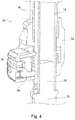
- the adjustable leg 10 shown in Figures 1 to 4 comprises an elongate inner leg part 12 a length 14 of which extends within an outer leg part 16, the inner leg part 12 being slidable relative to the outer leg part 16 so that the leg 10 as a whole is telescopically adjustable in length.
- the inner leg part 12 comprises a length 18 of cylindrical aluminium tubing 20 of substantially uniform cross-section. Along one side thereof there is a longitudinal recess 22. A plastics end-piece 24 forms a tight fit with an intended upper end 26 of the inner leg part 12, to close off that end.
- the intended lower end 28 of the tubing 20 receives as a tight fit and closure a spigot 30 of a foot 31 of the inner leg part 12, the foot 31 also comprising a short extension 32, terminated by the ball 34 of a ball and socket joint 36 between the foot 31 and a foot pad 38.
- the lower end 40 of the recess 22 is formed with an aperture 42.
- the outer leg part 16 comprises a length of cylindrical aluminium tubing 44 of sufficient internal diameter to accommodate the inner leg part 12 sufficiently to enable the latter to slide within in it but sufficiently tightly to ensure the inner and outer leg parts 12 and 16 remain co-linear.
- the upper end 46 of the tubing 44 is closed with a plastics end-piece 48, and an elongate compression spring 50 extends between and abuts against an underside of the end-piece 48 and the upper side of the end-piece 24, so as to urge the inner leg 12 downwardly relative to the outer lag part 16, so that it tends to increase the length of the telescopically adjustable leg 10.
- a plastics housing 52 accommodating a locking mechanism 54 is secured to the lower end 56 of the aluminium tubing 44 of the outer leg part 16.
- the inner leg part 12 extends through the housing 52.
- the housing 52 is formed with a cavity 58 within which extends a compression spring 60.
- This compression spring 60 surrounds a portion of the inner leg part 12, has its lower end 64 seated on the base 66 of the housing 52, and its upper end 68 in abutment with the lower side of a first locking member 70.
- the latter is in the form of a plate 70 having an aperture 72 through which extends the inner leg part 12.
- the plate 70 has one end 74 engaging a corner of the cavity 58 on one side of the leg 10, and slants upwardly therefrom to its other end 76 which is provided with a thumb-push 78.
- inner edges of its aperture 72 dig into the aluminium tubing 20 of the inner leg part 12.
- the upper wall 80 of the cavity 58 also slants to accommodate such a slant in the plate 40.
- a second locking member 82 is retained within the housing 52. It has an inner end 84 received in the aperture 42. It is slidable out of engagement with the aperture 42 against the force of a return spring 86 in the form of a compression spring 86 housed within the housing 52.
- the thumb-push 78 and the second locking member 82 are provided with respective slanting cam surfaces 88 and 90, such that when the thumb-push 78 is depressed by the user's thumb (not shown), not only is the first locking member 70 brought substantially at right angles to the inner leg part 12, but also the cam surfaces 88 and 90 engage one another so that the second locking member 82 is urged away from the inner leg part 12 and out of engagement with the aperture 42 against the force of the restoring spring 86.
- the inner leg part 12 is now free to slide within the outer leg part 16, downwardly under the forces of gravity and the compression spring 50 to an extended condition as shown in Figures 3 and 4 .
- the chair 100 parts of which are shown in Figure 5 has a seat part 102 and four legs each as shown in Figures 1 to 4 (but only one of which is fully shown in Figure 5 , parts of a second also being visible), so that the legs may be adjusted in length and the seat of the chair made horizontal regardless of how uneven the ground is.
- the fact that each foot pad 38 is swivellable by virtue of it being attached to the inner leg part 12 by a ball and socket joint facilitates uneven slope on the ground as well as uneven level, and also provides resistance to sinking in soft ground.
- the chair 100 When the chair 100 is prepared for use on uneven ground, the chair 100 may be held with its seat part 102 horizontal over the ground where the chair is to be situated, and the thumb-push 78 of each adjustable leg 10 depressed in turn with the user only needing one hand to do this, so that the foot pad 38 of the inner leg 12 of each leg 10 in turn drops to the ground. Subsequent release of the thumb-push 78 locks the leg at that length notwithstanding the weight of the user when he or she sits in the chair 100.
- each thumb-push 78 may be depressed in turn, with sufficient force acting on the leg 10 to urge the inner leg part 12 to be retracted into the outer leg part 16 until the inner end 84 of the second locking member 82 is in registration with the aperture 42, whereupon the thumb-push 78 is released and the inner leg part 12 is held in its fully retracted condition.
- the foot pad or pads 38 may be omitted if the leg or chair is not to be used on soft ground.
- the leg or legs each as shown in Figures 1 to 4 could be used on a bedchair, a wheelbarrow, a table, a container, a trolley or other article.
Landscapes
- Engineering & Computer Science (AREA)
- General Engineering & Computer Science (AREA)
- Mechanical Engineering (AREA)
- Life Sciences & Earth Sciences (AREA)
- Environmental Sciences (AREA)
- Animal Husbandry (AREA)
- Biodiversity & Conservation Biology (AREA)
- Rehabilitation Tools (AREA)
- Legs For Furniture In General (AREA)
- Chair Legs, Seat Parts, And Backrests (AREA)
Claims (8)
- Verstellbares Bein (10), das innere und äußere Beinteile (12 und 16) umfasst, von denen das innere Beinteil (12) innerhalb des äußeren Beinteils (16) verschiebbar ist, um zu ermöglichen, dass das Bein in der Länge teleskopisch verstellbar ist, wobei ein Verriegelungselement (70) vorhanden ist, das mit einer Öffnung (72) versehen ist, durch die das innere Beinteil (12) hindurchführt, wobei das Verriegelungselement (70) direkt oder indirekt am äußeren Beinteil (16) gehalten und elastisch gedrückt wird, um einen Winkel in Bezug auf das innere Beinteil (12) einzunehmen, so dass Kantenabschnitte, die die Öffnung (72) definieren, in Eingriff mit dem inneren Beinteil (12) kommen und es relativ zum äußeren Beinteil (16) in Position halten, wobei das verstellbare Bein (10) mit einem zweiten Verriegelungselement (82) versehen ist, das in den und aus dem Eingriff mit dem inneren Beinteil (12) bewegt werden kann, wobei das erstgenannte Verriegelungselement (70) und das zweite Verriegelungselement (82) mit miteinander in Eingriff bringbaren Abschnitten versehen sind, durch die eine Bewegung des erstgenannten Verriegelungselements (70) aus dem Eingriff mit dem inneren Beinteil (12) eine Bewegung des zweiten Verriegelungselements (82) aus dem Eingriff mit dem inneren Beinteil (12) bewirkt, dadurch gekennzeichnet, dass das innere Beinteil (12) mit einem Eingriffsabschnitt versehen ist, um den Eingriff zwischen dem zweiten Verriegelungselement (82) und dem inneren Beinteil (12) zu erleichtern, wobei der Eingriffsabschnitt eine Öffnung oder Aussparung (42) umfasst, die einen Endabschnitt (84) des zweiten Verriegelungselements (82) aufnimmt, wenn dieses mit dem inneren Beinteil (12) im Eingriff steht.
- Verstellbares Bein (10) nach Anspruch 1, dadurch gekennzeichnet, dass das zweite Verriegelungselement (82) elastisch in Eingriff mit dem inneren Beinteil (12) gedrückt wird.
- Verstellbares Bein (10) nach Anspruch 2, dadurch gekennzeichnet, dass das zweite Verriegelungselement (82) durch eine Druckfeder (86) elastisch in Eingriff mit dem inneren Beinteil (12) gedrückt wird.
- Verstellbares Bein (10) nach Anspruch 3, dadurch gekennzeichnet, dass die Druckfeder (86), die das zweite Verriegelungselement (82) in Eingriff mit dem inneren Beinteil (12) drückt, in einem Gehäuse (52) untergebracht ist, das auch wenigstens einen Teil des erstgenannten Verriegelungselements (70) aufnimmt.
- Verstellbares Bein (10) nach einem der vorstehenden Ansprüche, dadurch gekennzeichnet, dass einer oder beide der miteinander in Eingriff bringbaren Abschnitte mit einem Nocken (88 oder 90) versehen sind, um ein solches Außer-Eingriff-Bringen herbeizuführen.
- Verstellbares Bein (10) nach einem der vorstehenden Ansprüche, dadurch gekennzeichnet, dass sich der Eingriffsabschnitt an einem Ende des verfügbaren Verfahrweges des inneren Beinteils (12) relativ zum zweiten Verriegelungselement (82) befindet.
- Verstellbares Bein (10) nach einem der vorstehenden Ansprüche, dadurch gekennzeichnet, dass innerhalb des äußeren Beinteils (16) eine in Längsrichtung ausgerichtete Druckfeder (50) angeordnet ist und mit dem inneren Beinteil (12) in Eingriff kommt, um dieses in eine Richtung zu drücken mit der Tendenz, die Länge des teleskopisch verstellbaren Beins (10) zu vergrößern.
- Gegenstand, der einen Stuhl, eine Liege, eine Schubkarre, einen Tisch, einen Behälter, einen Trolley oder einen anderen Gegenstand mit wenigstens einem verstellbaren Bein (10) gemäß einem der vorstehenden Ansprüche umfasst.
Priority Applications (1)
| Application Number | Priority Date | Filing Date | Title |
|---|---|---|---|
| PL17020562T PL3369340T3 (pl) | 2017-03-01 | 2017-12-07 | Noga regulowana i wyrób z nogą regulowaną |
Applications Claiming Priority (1)
| Application Number | Priority Date | Filing Date | Title |
|---|---|---|---|
| GB1703333.3A GB2560178A (en) | 2017-03-01 | 2017-03-01 | An adjustable leg, and an article with an adjustable leg |
Publications (2)
| Publication Number | Publication Date |
|---|---|
| EP3369340A1 EP3369340A1 (de) | 2018-09-05 |
| EP3369340B1 true EP3369340B1 (de) | 2019-11-13 |
Family
ID=58544278
Family Applications (1)
| Application Number | Title | Priority Date | Filing Date |
|---|---|---|---|
| EP17020562.9A Active EP3369340B1 (de) | 2017-03-01 | 2017-12-07 | Verstellbares bein und artikel mit einem verstellbaren bein |
Country Status (3)
| Country | Link |
|---|---|
| EP (1) | EP3369340B1 (de) |
| GB (1) | GB2560178A (de) |
| PL (1) | PL3369340T3 (de) |
Families Citing this family (1)
| Publication number | Priority date | Publication date | Assignee | Title |
|---|---|---|---|---|
| CN115723876A (zh) * | 2021-08-27 | 2023-03-03 | Oppo广东移动通信有限公司 | 机器人及其腿部组件 |
Family Cites Families (13)
| Publication number | Priority date | Publication date | Assignee | Title |
|---|---|---|---|---|
| US836303A (en) * | 1906-04-26 | 1906-11-20 | Carl V J Christensen | Automatic-locking collar. |
| US3307820A (en) * | 1964-12-30 | 1967-03-07 | Martin Brothers Electric Compa | Chair lift mechanism |
| US3737136A (en) * | 1972-03-29 | 1973-06-05 | G Snurr | Adjustable height support |
| DK154523C (da) * | 1984-02-23 | 1989-05-16 | Wassmann Mogens | Laasering og anvendelse af laaseringen |
| DE3620520C2 (de) * | 1986-06-19 | 1995-02-02 | Peter Kraus | Auf einer unebenen Fläche abstellbare, formstabile Vorrichtung sowie Niveauausgleichselement für diese |
| GB9116354D0 (en) * | 1991-07-29 | 1991-09-11 | R J C U K Limited | Telescopic adjustable leg |
| FR2827921B1 (fr) * | 2001-07-24 | 2007-05-25 | Pascal Guidetti | Dispositif de blocage de deux elements allonges telescopiques |
| WO2008040034A2 (en) * | 2006-09-28 | 2008-04-03 | Aluminium Leisure Furniture (Pty) Ltd | A pedestal |
| GB2483876A (en) * | 2010-09-22 | 2012-03-28 | Nicholas David Le Sueur | Seat height adjustment mechanism |
| US8544392B2 (en) * | 2011-02-04 | 2013-10-01 | Jack Wynn Fields | Releasable engagement apparatus |
| CN204393140U (zh) * | 2015-01-16 | 2015-06-17 | 朱吉利 | 钓鱼箱伸缩脚 |
| GB2537662B (en) * | 2015-04-22 | 2020-01-01 | Preston Innovations Ltd | Leg adjuster |
| DE202018100013U1 (de) * | 2018-01-02 | 2018-01-15 | Zhejiang Hengfeng Top Leisure Co., Ltd. | Höhenverstellbares Bein für Campingartikel |
-
2017
- 2017-03-01 GB GB1703333.3A patent/GB2560178A/en not_active Withdrawn
- 2017-12-07 EP EP17020562.9A patent/EP3369340B1/de active Active
- 2017-12-07 PL PL17020562T patent/PL3369340T3/pl unknown
Non-Patent Citations (1)
| Title |
|---|
| None * |
Also Published As
| Publication number | Publication date |
|---|---|
| GB201703333D0 (en) | 2017-04-12 |
| EP3369340A1 (de) | 2018-09-05 |
| PL3369340T3 (pl) | 2020-04-30 |
| GB2560178A (en) | 2018-09-05 |
Similar Documents
| Publication | Publication Date | Title |
|---|---|---|
| US9651073B2 (en) | Locking mechanism for telescoping members | |
| US9149111B1 (en) | Collapsible tray table | |
| US8439057B2 (en) | Walking stick | |
| USD780861S1 (en) | Locking barbell collar | |
| US8967579B2 (en) | Angle inclining structure for a desk | |
| US9095216B2 (en) | Always level folding chair | |
| US7575207B2 (en) | Collapsible stand for bicycle | |
| US9993064B2 (en) | Rotatable handle attachable to an object having a longitudinal extent | |
| EP2865290A1 (de) | In einen Stuhl verwandelbarer Gehstock | |
| US9155394B1 (en) | Chair with slide-out leg rest | |
| US2893765A (en) | Extensible torque rod | |
| US9644407B1 (en) | Adjustable door wedge with a locking mechanism | |
| EP3107421A1 (de) | Sockelvorrichtung | |
| US20150107636A1 (en) | Chair-convertible walking stick | |
| US10864132B1 (en) | Upright extension for personal walkers | |
| US20180207788A1 (en) | Adjustable sawhorse | |
| EP3369340A1 (de) | Verstellbares bein und artikel mit einem verstellbaren bein | |
| CA2237340A1 (en) | Improved collapsible crutch | |
| EP2975274B1 (de) | Klemmenanordnung | |
| FR3044235A1 (fr) | Poignee et sa dragonne amovible de baton de ski ou de marche | |
| WO2008088268A8 (en) | Ladder with two side legs and an extension leg to bepressed against ground | |
| US20190023357A1 (en) | Foldable Watercraft Table | |
| GB2318505A (en) | Telescopic leg | |
| CA3040561C (en) | Attachment for facilitating securing of a load with a strap, rope or the like | |
| GB2474505A (en) | An adjustable leg for furniture |
Legal Events
| Date | Code | Title | Description |
|---|---|---|---|
| PUAI | Public reference made under article 153(3) epc to a published international application that has entered the european phase |
Free format text: ORIGINAL CODE: 0009012 |
|
| STAA | Information on the status of an ep patent application or granted ep patent |
Free format text: STATUS: THE APPLICATION HAS BEEN PUBLISHED |
|
| AK | Designated contracting states |
Kind code of ref document: A1 Designated state(s): AL AT BE BG CH CY CZ DE DK EE ES FI FR GB GR HR HU IE IS IT LI LT LU LV MC MK MT NL NO PL PT RO RS SE SI SK SM TR |
|
| AX | Request for extension of the european patent |
Extension state: BA ME |
|
| STAA | Information on the status of an ep patent application or granted ep patent |
Free format text: STATUS: REQUEST FOR EXAMINATION WAS MADE |
|
| 17P | Request for examination filed |
Effective date: 20181210 |
|
| RBV | Designated contracting states (corrected) |
Designated state(s): AL AT BE BG CH CY CZ DE DK EE ES FI FR GB GR HR HU IE IS IT LI LT LU LV MC MK MT NL NO PL PT RO RS SE SI SK SM TR |
|
| GRAP | Despatch of communication of intention to grant a patent |
Free format text: ORIGINAL CODE: EPIDOSNIGR1 |
|
| STAA | Information on the status of an ep patent application or granted ep patent |
Free format text: STATUS: GRANT OF PATENT IS INTENDED |
|
| RIC1 | Information provided on ipc code assigned before grant |
Ipc: A47B 9/08 20060101AFI20190718BHEP Ipc: A47B 9/14 20060101ALN20190718BHEP Ipc: A47B 9/02 20060101ALN20190718BHEP Ipc: A47B 9/20 20060101ALN20190718BHEP |
|
| INTG | Intention to grant announced |
Effective date: 20190802 |
|
| GRAS | Grant fee paid |
Free format text: ORIGINAL CODE: EPIDOSNIGR3 |
|
| GRAA | (expected) grant |
Free format text: ORIGINAL CODE: 0009210 |
|
| STAA | Information on the status of an ep patent application or granted ep patent |
Free format text: STATUS: THE PATENT HAS BEEN GRANTED |
|
| AK | Designated contracting states |
Kind code of ref document: B1 Designated state(s): AL AT BE BG CH CY CZ DE DK EE ES FI FR GB GR HR HU IE IS IT LI LT LU LV MC MK MT NL NO PL PT RO RS SE SI SK SM TR |
|
| REG | Reference to a national code |
Ref country code: CH Ref legal event code: EP Ref country code: AT Ref legal event code: REF Ref document number: 1200791 Country of ref document: AT Kind code of ref document: T Effective date: 20191115 |
|
| REG | Reference to a national code |
Ref country code: DE Ref legal event code: R096 Ref document number: 602017008538 Country of ref document: DE |
|
| REG | Reference to a national code |
Ref country code: IE Ref legal event code: FG4D |
|
| REG | Reference to a national code |
Ref country code: NL Ref legal event code: FP |
|
| REG | Reference to a national code |
Ref country code: LT Ref legal event code: MG4D |
|
| PG25 | Lapsed in a contracting state [announced via postgrant information from national office to epo] |
Ref country code: PT Free format text: LAPSE BECAUSE OF FAILURE TO SUBMIT A TRANSLATION OF THE DESCRIPTION OR TO PAY THE FEE WITHIN THE PRESCRIBED TIME-LIMIT Effective date: 20200313 Ref country code: LV Free format text: LAPSE BECAUSE OF FAILURE TO SUBMIT A TRANSLATION OF THE DESCRIPTION OR TO PAY THE FEE WITHIN THE PRESCRIBED TIME-LIMIT Effective date: 20191113 Ref country code: SE Free format text: LAPSE BECAUSE OF FAILURE TO SUBMIT A TRANSLATION OF THE DESCRIPTION OR TO PAY THE FEE WITHIN THE PRESCRIBED TIME-LIMIT Effective date: 20191113 Ref country code: GR Free format text: LAPSE BECAUSE OF FAILURE TO SUBMIT A TRANSLATION OF THE DESCRIPTION OR TO PAY THE FEE WITHIN THE PRESCRIBED TIME-LIMIT Effective date: 20200214 Ref country code: FI Free format text: LAPSE BECAUSE OF FAILURE TO SUBMIT A TRANSLATION OF THE DESCRIPTION OR TO PAY THE FEE WITHIN THE PRESCRIBED TIME-LIMIT Effective date: 20191113 Ref country code: NO Free format text: LAPSE BECAUSE OF FAILURE TO SUBMIT A TRANSLATION OF THE DESCRIPTION OR TO PAY THE FEE WITHIN THE PRESCRIBED TIME-LIMIT Effective date: 20200213 Ref country code: BG Free format text: LAPSE BECAUSE OF FAILURE TO SUBMIT A TRANSLATION OF THE DESCRIPTION OR TO PAY THE FEE WITHIN THE PRESCRIBED TIME-LIMIT Effective date: 20200213 Ref country code: LT Free format text: LAPSE BECAUSE OF FAILURE TO SUBMIT A TRANSLATION OF THE DESCRIPTION OR TO PAY THE FEE WITHIN THE PRESCRIBED TIME-LIMIT Effective date: 20191113 |
|
| PG25 | Lapsed in a contracting state [announced via postgrant information from national office to epo] |
Ref country code: RS Free format text: LAPSE BECAUSE OF FAILURE TO SUBMIT A TRANSLATION OF THE DESCRIPTION OR TO PAY THE FEE WITHIN THE PRESCRIBED TIME-LIMIT Effective date: 20191113 Ref country code: HR Free format text: LAPSE BECAUSE OF FAILURE TO SUBMIT A TRANSLATION OF THE DESCRIPTION OR TO PAY THE FEE WITHIN THE PRESCRIBED TIME-LIMIT Effective date: 20191113 Ref country code: IS Free format text: LAPSE BECAUSE OF FAILURE TO SUBMIT A TRANSLATION OF THE DESCRIPTION OR TO PAY THE FEE WITHIN THE PRESCRIBED TIME-LIMIT Effective date: 20200313 |
|
| PG25 | Lapsed in a contracting state [announced via postgrant information from national office to epo] |
Ref country code: AL Free format text: LAPSE BECAUSE OF FAILURE TO SUBMIT A TRANSLATION OF THE DESCRIPTION OR TO PAY THE FEE WITHIN THE PRESCRIBED TIME-LIMIT Effective date: 20191113 |
|
| PG25 | Lapsed in a contracting state [announced via postgrant information from national office to epo] |
Ref country code: EE Free format text: LAPSE BECAUSE OF FAILURE TO SUBMIT A TRANSLATION OF THE DESCRIPTION OR TO PAY THE FEE WITHIN THE PRESCRIBED TIME-LIMIT Effective date: 20191113 Ref country code: RO Free format text: LAPSE BECAUSE OF FAILURE TO SUBMIT A TRANSLATION OF THE DESCRIPTION OR TO PAY THE FEE WITHIN THE PRESCRIBED TIME-LIMIT Effective date: 20191113 Ref country code: ES Free format text: LAPSE BECAUSE OF FAILURE TO SUBMIT A TRANSLATION OF THE DESCRIPTION OR TO PAY THE FEE WITHIN THE PRESCRIBED TIME-LIMIT Effective date: 20191113 Ref country code: DK Free format text: LAPSE BECAUSE OF FAILURE TO SUBMIT A TRANSLATION OF THE DESCRIPTION OR TO PAY THE FEE WITHIN THE PRESCRIBED TIME-LIMIT Effective date: 20191113 |
|
| REG | Reference to a national code |
Ref country code: DE Ref legal event code: R097 Ref document number: 602017008538 Country of ref document: DE |
|
| PG25 | Lapsed in a contracting state [announced via postgrant information from national office to epo] |
Ref country code: SM Free format text: LAPSE BECAUSE OF FAILURE TO SUBMIT A TRANSLATION OF THE DESCRIPTION OR TO PAY THE FEE WITHIN THE PRESCRIBED TIME-LIMIT Effective date: 20191113 Ref country code: MC Free format text: LAPSE BECAUSE OF FAILURE TO SUBMIT A TRANSLATION OF THE DESCRIPTION OR TO PAY THE FEE WITHIN THE PRESCRIBED TIME-LIMIT Effective date: 20191113 Ref country code: SK Free format text: LAPSE BECAUSE OF FAILURE TO SUBMIT A TRANSLATION OF THE DESCRIPTION OR TO PAY THE FEE WITHIN THE PRESCRIBED TIME-LIMIT Effective date: 20191113 |
|
| PLBE | No opposition filed within time limit |
Free format text: ORIGINAL CODE: 0009261 |
|
| STAA | Information on the status of an ep patent application or granted ep patent |
Free format text: STATUS: NO OPPOSITION FILED WITHIN TIME LIMIT |
|
| 26N | No opposition filed |
Effective date: 20200814 |
|
| PG25 | Lapsed in a contracting state [announced via postgrant information from national office to epo] |
Ref country code: IE Free format text: LAPSE BECAUSE OF NON-PAYMENT OF DUE FEES Effective date: 20191207 Ref country code: LU Free format text: LAPSE BECAUSE OF NON-PAYMENT OF DUE FEES Effective date: 20191207 |
|
| PG25 | Lapsed in a contracting state [announced via postgrant information from national office to epo] |
Ref country code: SI Free format text: LAPSE BECAUSE OF FAILURE TO SUBMIT A TRANSLATION OF THE DESCRIPTION OR TO PAY THE FEE WITHIN THE PRESCRIBED TIME-LIMIT Effective date: 20191113 |
|
| PG25 | Lapsed in a contracting state [announced via postgrant information from national office to epo] |
Ref country code: CY Free format text: LAPSE BECAUSE OF FAILURE TO SUBMIT A TRANSLATION OF THE DESCRIPTION OR TO PAY THE FEE WITHIN THE PRESCRIBED TIME-LIMIT Effective date: 20191113 |
|
| PG25 | Lapsed in a contracting state [announced via postgrant information from national office to epo] |
Ref country code: HU Free format text: LAPSE BECAUSE OF FAILURE TO SUBMIT A TRANSLATION OF THE DESCRIPTION OR TO PAY THE FEE WITHIN THE PRESCRIBED TIME-LIMIT; INVALID AB INITIO Effective date: 20171207 Ref country code: MT Free format text: LAPSE BECAUSE OF FAILURE TO SUBMIT A TRANSLATION OF THE DESCRIPTION OR TO PAY THE FEE WITHIN THE PRESCRIBED TIME-LIMIT Effective date: 20191113 |
|
| REG | Reference to a national code |
Ref country code: CH Ref legal event code: PL |
|
| PG25 | Lapsed in a contracting state [announced via postgrant information from national office to epo] |
Ref country code: LI Free format text: LAPSE BECAUSE OF NON-PAYMENT OF DUE FEES Effective date: 20201231 Ref country code: CH Free format text: LAPSE BECAUSE OF NON-PAYMENT OF DUE FEES Effective date: 20201231 |
|
| REG | Reference to a national code |
Ref country code: AT Ref legal event code: UEP Ref document number: 1200791 Country of ref document: AT Kind code of ref document: T Effective date: 20191113 |
|
| PG25 | Lapsed in a contracting state [announced via postgrant information from national office to epo] |
Ref country code: TR Free format text: LAPSE BECAUSE OF FAILURE TO SUBMIT A TRANSLATION OF THE DESCRIPTION OR TO PAY THE FEE WITHIN THE PRESCRIBED TIME-LIMIT Effective date: 20191113 |
|
| PG25 | Lapsed in a contracting state [announced via postgrant information from national office to epo] |
Ref country code: MK Free format text: LAPSE BECAUSE OF FAILURE TO SUBMIT A TRANSLATION OF THE DESCRIPTION OR TO PAY THE FEE WITHIN THE PRESCRIBED TIME-LIMIT Effective date: 20191113 |
|
| PGFP | Annual fee paid to national office [announced via postgrant information from national office to epo] |
Ref country code: NL Payment date: 20231226 Year of fee payment: 7 Ref country code: IT Payment date: 20231219 Year of fee payment: 7 Ref country code: FR Payment date: 20231226 Year of fee payment: 7 Ref country code: CZ Payment date: 20231128 Year of fee payment: 7 Ref country code: AT Payment date: 20231229 Year of fee payment: 7 |
|
| PGFP | Annual fee paid to national office [announced via postgrant information from national office to epo] |
Ref country code: PL Payment date: 20231128 Year of fee payment: 7 Ref country code: BE Payment date: 20231226 Year of fee payment: 7 |
|
| PGFP | Annual fee paid to national office [announced via postgrant information from national office to epo] |
Ref country code: DE Payment date: 20231227 Year of fee payment: 7 |
|
| REG | Reference to a national code |
Ref country code: DE Ref legal event code: R119 Ref document number: 602017008538 Country of ref document: DE |
|
| PG25 | Lapsed in a contracting state [announced via postgrant information from national office to epo] |
Ref country code: CZ Free format text: LAPSE BECAUSE OF NON-PAYMENT OF DUE FEES Effective date: 20241207 |
|
| REG | Reference to a national code |
Ref country code: NL Ref legal event code: MM Effective date: 20250101 |
|
| REG | Reference to a national code |
Ref country code: AT Ref legal event code: MM01 Ref document number: 1200791 Country of ref document: AT Kind code of ref document: T Effective date: 20241207 |
|
| PG25 | Lapsed in a contracting state [announced via postgrant information from national office to epo] |
Ref country code: NL Free format text: LAPSE BECAUSE OF NON-PAYMENT OF DUE FEES Effective date: 20250101 |
|
| REG | Reference to a national code |
Ref country code: BE Ref legal event code: MM Effective date: 20241231 |
|
| PG25 | Lapsed in a contracting state [announced via postgrant information from national office to epo] |
Ref country code: DE Free format text: LAPSE BECAUSE OF NON-PAYMENT OF DUE FEES Effective date: 20250701 |
|
| PG25 | Lapsed in a contracting state [announced via postgrant information from national office to epo] |
Ref country code: IT Free format text: LAPSE BECAUSE OF NON-PAYMENT OF DUE FEES Effective date: 20241207 |
|
| PG25 | Lapsed in a contracting state [announced via postgrant information from national office to epo] |
Ref country code: BE Free format text: LAPSE BECAUSE OF NON-PAYMENT OF DUE FEES Effective date: 20241231 |
|
| PG25 | Lapsed in a contracting state [announced via postgrant information from national office to epo] |
Ref country code: AT Free format text: LAPSE BECAUSE OF NON-PAYMENT OF DUE FEES Effective date: 20241207 Ref country code: FR Free format text: LAPSE BECAUSE OF NON-PAYMENT OF DUE FEES Effective date: 20241231 |
|
| PGFP | Annual fee paid to national office [announced via postgrant information from national office to epo] |
Ref country code: GB Payment date: 20251223 Year of fee payment: 9 |