EP3368889B1 - A charging unit for a particle monitoring apparatus, and a particle monitoring apparatus - Google Patents
A charging unit for a particle monitoring apparatus, and a particle monitoring apparatus Download PDFInfo
- Publication number
- EP3368889B1 EP3368889B1 EP16859133.7A EP16859133A EP3368889B1 EP 3368889 B1 EP3368889 B1 EP 3368889B1 EP 16859133 A EP16859133 A EP 16859133A EP 3368889 B1 EP3368889 B1 EP 3368889B1
- Authority
- EP
- European Patent Office
- Prior art keywords
- electrode
- signal
- particles
- spc1
- electric current
- Prior art date
- Legal status (The legal status is an assumption and is not a legal conclusion. Google has not performed a legal analysis and makes no representation as to the accuracy of the status listed.)
- Active
Links
- 239000002245 particle Substances 0.000 title claims description 215
- 238000012544 monitoring process Methods 0.000 title claims description 111
- 239000007789 gas Substances 0.000 claims description 76
- 239000000443 aerosol Substances 0.000 claims description 69
- 238000005259 measurement Methods 0.000 claims description 60
- 238000000034 method Methods 0.000 claims description 50
- 238000005040 ion trap Methods 0.000 claims description 23
- 150000002500 ions Chemical class 0.000 claims description 22
- 238000010438 heat treatment Methods 0.000 claims description 21
- 238000005070 sampling Methods 0.000 claims description 13
- 238000002485 combustion reaction Methods 0.000 claims description 10
- UGFAIRIUMAVXCW-UHFFFAOYSA-N Carbon monoxide Chemical compound [O+]#[C-] UGFAIRIUMAVXCW-UHFFFAOYSA-N 0.000 claims description 5
- 239000003546 flue gas Substances 0.000 claims description 4
- 102000012677 DET1 Human genes 0.000 description 62
- 101150113651 DET1 gene Proteins 0.000 description 62
- 238000012806 monitoring device Methods 0.000 description 59
- 230000008859 change Effects 0.000 description 37
- 230000008569 process Effects 0.000 description 36
- 101001022148 Homo sapiens Furin Proteins 0.000 description 33
- 101000701936 Homo sapiens Signal peptidase complex subunit 1 Proteins 0.000 description 33
- 102100030313 Signal peptidase complex subunit 1 Human genes 0.000 description 33
- 101100060492 Ustilago maydis (strain 521 / FGSC 9021) CMU1 gene Proteins 0.000 description 31
- 238000002474 experimental method Methods 0.000 description 16
- 102000007315 Telomeric Repeat Binding Protein 1 Human genes 0.000 description 15
- 108010033711 Telomeric Repeat Binding Protein 1 Proteins 0.000 description 15
- 101100129750 Arabidopsis thaliana MDN1 gene Proteins 0.000 description 12
- 101100049029 Rattus norvegicus Atp6v0e1 gene Proteins 0.000 description 12
- 101100327317 Saccharomyces cerevisiae (strain ATCC 204508 / S288c) CDC1 gene Proteins 0.000 description 12
- 101100338893 Arabidopsis thaliana HHO5 gene Proteins 0.000 description 11
- 101100410399 Arabidopsis thaliana PUMP2 gene Proteins 0.000 description 11
- 108010037490 Peptidyl-Prolyl Cis-Trans Isomerase NIMA-Interacting 4 Proteins 0.000 description 11
- 102100031653 Peptidyl-prolyl cis-trans isomerase NIMA-interacting 4 Human genes 0.000 description 11
- 101150087393 PIN3 gene Proteins 0.000 description 10
- 238000004891 communication Methods 0.000 description 9
- 230000005684 electric field Effects 0.000 description 9
- 101000615747 Homo sapiens tRNA-splicing endonuclease subunit Sen2 Proteins 0.000 description 8
- 108010059419 NIMA-Interacting Peptidylprolyl Isomerase Proteins 0.000 description 8
- 102100026114 Peptidyl-prolyl cis-trans isomerase NIMA-interacting 1 Human genes 0.000 description 8
- 230000000694 effects Effects 0.000 description 8
- 102100021774 tRNA-splicing endonuclease subunit Sen2 Human genes 0.000 description 8
- 238000012360 testing method Methods 0.000 description 8
- 102100037700 DNA mismatch repair protein Msh3 Human genes 0.000 description 7
- 101100238606 Homo sapiens MSH3 gene Proteins 0.000 description 7
- 238000004590 computer program Methods 0.000 description 7
- 238000010790 dilution Methods 0.000 description 7
- 239000012895 dilution Substances 0.000 description 7
- 239000000446 fuel Substances 0.000 description 7
- 238000005303 weighing Methods 0.000 description 7
- 239000002184 metal Substances 0.000 description 6
- 230000002123 temporal effect Effects 0.000 description 6
- 239000003570 air Substances 0.000 description 5
- 230000002547 anomalous effect Effects 0.000 description 5
- 230000001276 controlling effect Effects 0.000 description 5
- 230000003628 erosive effect Effects 0.000 description 5
- 101100452003 Caenorhabditis elegans ape-1 gene Proteins 0.000 description 4
- 101000685663 Homo sapiens Sodium/nucleoside cotransporter 1 Proteins 0.000 description 4
- 102100023116 Sodium/nucleoside cotransporter 1 Human genes 0.000 description 4
- 239000000615 nonconductor Substances 0.000 description 4
- 239000000126 substance Substances 0.000 description 4
- 101100204393 Arabidopsis thaliana SUMO2 gene Proteins 0.000 description 3
- 101150112492 SUM-1 gene Proteins 0.000 description 3
- 101150096255 SUMO1 gene Proteins 0.000 description 3
- 101100417240 Saccharomyces cerevisiae (strain ATCC 204508 / S288c) RPN2 gene Proteins 0.000 description 3
- 101100311460 Schizosaccharomyces pombe (strain 972 / ATCC 24843) sum2 gene Proteins 0.000 description 3
- 238000011109 contamination Methods 0.000 description 3
- 238000000151 deposition Methods 0.000 description 3
- 239000000203 mixture Substances 0.000 description 3
- 239000012716 precipitator Substances 0.000 description 3
- 238000012545 processing Methods 0.000 description 3
- 238000010998 test method Methods 0.000 description 3
- 230000002159 abnormal effect Effects 0.000 description 2
- 239000000654 additive Substances 0.000 description 2
- 230000000996 additive effect Effects 0.000 description 2
- 239000012080 ambient air Substances 0.000 description 2
- 230000005540 biological transmission Effects 0.000 description 2
- 230000015572 biosynthetic process Effects 0.000 description 2
- 230000003197 catalytic effect Effects 0.000 description 2
- 239000004020 conductor Substances 0.000 description 2
- 238000009792 diffusion process Methods 0.000 description 2
- 238000007865 diluting Methods 0.000 description 2
- 238000009826 distribution Methods 0.000 description 2
- 238000003754 machining Methods 0.000 description 2
- 230000007246 mechanism Effects 0.000 description 2
- 230000007935 neutral effect Effects 0.000 description 2
- 230000004044 response Effects 0.000 description 2
- 238000009423 ventilation Methods 0.000 description 2
- 238000010146 3D printing Methods 0.000 description 1
- 206010000117 Abnormal behaviour Diseases 0.000 description 1
- 101100031730 Arabidopsis thaliana PUMP1 gene Proteins 0.000 description 1
- 238000012935 Averaging Methods 0.000 description 1
- 102100040862 Dual specificity protein kinase CLK1 Human genes 0.000 description 1
- 101000749294 Homo sapiens Dual specificity protein kinase CLK1 Proteins 0.000 description 1
- 101100130645 Homo sapiens MMP7 gene Proteins 0.000 description 1
- 101000908580 Homo sapiens Spliceosome RNA helicase DDX39B Proteins 0.000 description 1
- 102100030417 Matrilysin Human genes 0.000 description 1
- 101100375588 Oryza sativa subsp. japonica YAB2 gene Proteins 0.000 description 1
- 229910019250 POS3 Inorganic materials 0.000 description 1
- 102100024690 Spliceosome RNA helicase DDX39B Human genes 0.000 description 1
- 230000006399 behavior Effects 0.000 description 1
- 239000003245 coal Substances 0.000 description 1
- 238000009833 condensation Methods 0.000 description 1
- 230000005494 condensation Effects 0.000 description 1
- 230000002596 correlated effect Effects 0.000 description 1
- 238000010219 correlation analysis Methods 0.000 description 1
- 230000007423 decrease Effects 0.000 description 1
- 230000003247 decreasing effect Effects 0.000 description 1
- 230000008021 deposition Effects 0.000 description 1
- 239000012777 electrically insulating material Substances 0.000 description 1
- 230000007613 environmental effect Effects 0.000 description 1
- 238000011156 evaluation Methods 0.000 description 1
- 238000013213 extrapolation Methods 0.000 description 1
- 239000000835 fiber Substances 0.000 description 1
- 238000001914 filtration Methods 0.000 description 1
- 239000011888 foil Substances 0.000 description 1
- 230000006870 function Effects 0.000 description 1
- 230000001939 inductive effect Effects 0.000 description 1
- 230000004941 influx Effects 0.000 description 1
- 239000007788 liquid Substances 0.000 description 1
- 238000004519 manufacturing process Methods 0.000 description 1
- 238000012986 modification Methods 0.000 description 1
- 230000004048 modification Effects 0.000 description 1
- 238000000465 moulding Methods 0.000 description 1
- 230000003287 optical effect Effects 0.000 description 1
- 230000002572 peristaltic effect Effects 0.000 description 1
- 239000007787 solid Substances 0.000 description 1
- 230000003595 spectral effect Effects 0.000 description 1
- 230000001960 triggered effect Effects 0.000 description 1
- 238000011144 upstream manufacturing Methods 0.000 description 1
- 230000000007 visual effect Effects 0.000 description 1
Images


Classifications
-
- G—PHYSICS
- G01—MEASURING; TESTING
- G01N—INVESTIGATING OR ANALYSING MATERIALS BY DETERMINING THEIR CHEMICAL OR PHYSICAL PROPERTIES
- G01N27/00—Investigating or analysing materials by the use of electric, electrochemical, or magnetic means
- G01N27/62—Investigating or analysing materials by the use of electric, electrochemical, or magnetic means by investigating the ionisation of gases, e.g. aerosols; by investigating electric discharges, e.g. emission of cathode
- G01N27/68—Investigating or analysing materials by the use of electric, electrochemical, or magnetic means by investigating the ionisation of gases, e.g. aerosols; by investigating electric discharges, e.g. emission of cathode using electric discharge to ionise a gas
- G01N27/70—Investigating or analysing materials by the use of electric, electrochemical, or magnetic means by investigating the ionisation of gases, e.g. aerosols; by investigating electric discharges, e.g. emission of cathode using electric discharge to ionise a gas and measuring current or voltage
-
- H—ELECTRICITY
- H01—ELECTRIC ELEMENTS
- H01T—SPARK GAPS; OVERVOLTAGE ARRESTERS USING SPARK GAPS; SPARKING PLUGS; CORONA DEVICES; GENERATING IONS TO BE INTRODUCED INTO NON-ENCLOSED GASES
- H01T19/00—Devices providing for corona discharge
- H01T19/04—Devices providing for corona discharge having pointed electrodes
-
- G—PHYSICS
- G01—MEASURING; TESTING
- G01M—TESTING STATIC OR DYNAMIC BALANCE OF MACHINES OR STRUCTURES; TESTING OF STRUCTURES OR APPARATUS, NOT OTHERWISE PROVIDED FOR
- G01M15/00—Testing of engines
- G01M15/04—Testing internal-combustion engines
- G01M15/10—Testing internal-combustion engines by monitoring exhaust gases or combustion flame
-
- G—PHYSICS
- G01—MEASURING; TESTING
- G01N—INVESTIGATING OR ANALYSING MATERIALS BY DETERMINING THEIR CHEMICAL OR PHYSICAL PROPERTIES
- G01N15/00—Investigating characteristics of particles; Investigating permeability, pore-volume, or surface-area of porous materials
- G01N15/06—Investigating concentration of particle suspensions
- G01N15/0606—Investigating concentration of particle suspensions by collecting particles on a support
- G01N15/0618—Investigating concentration of particle suspensions by collecting particles on a support of the filter type
-
- G—PHYSICS
- G01—MEASURING; TESTING
- G01N—INVESTIGATING OR ANALYSING MATERIALS BY DETERMINING THEIR CHEMICAL OR PHYSICAL PROPERTIES
- G01N15/00—Investigating characteristics of particles; Investigating permeability, pore-volume, or surface-area of porous materials
- G01N15/06—Investigating concentration of particle suspensions
- G01N15/0656—Investigating concentration of particle suspensions using electric, e.g. electrostatic methods or magnetic methods
-
- G—PHYSICS
- G01—MEASURING; TESTING
- G01N—INVESTIGATING OR ANALYSING MATERIALS BY DETERMINING THEIR CHEMICAL OR PHYSICAL PROPERTIES
- G01N15/00—Investigating characteristics of particles; Investigating permeability, pore-volume, or surface-area of porous materials
- G01N2015/0038—Investigating nanoparticles
-
- G—PHYSICS
- G01—MEASURING; TESTING
- G01N—INVESTIGATING OR ANALYSING MATERIALS BY DETERMINING THEIR CHEMICAL OR PHYSICAL PROPERTIES
- G01N15/00—Investigating characteristics of particles; Investigating permeability, pore-volume, or surface-area of porous materials
- G01N2015/0042—Investigating dispersion of solids
- G01N2015/0046—Investigating dispersion of solids in gas, e.g. smoke
Definitions
- the apparatus may be used for detecting rapid changes of the aerosol concentration.
- the response time of the monitoring signal may be e.g. shorter than 1 s, or even shorter than 0.1 s.
- the additional measuring instrument may be a particle collecting unit, which comprises a particle filter.
- the additional measuring instrument may be arranged to capture aerosol particles to the particle filter during a particle collecting period.
- the total mass of particles collected by the filter may be determined by a gravimetric method, and the average mass concentration of the particles may be determined by dividing the total mass with the total volume of gas guided through the filter during the particle collecting period.
- the total mass of particles collected by the filter may be determined by weighing the filter after the collecting time period. Collecting a sufficient amount of particles may require a minimum time period, so as to attain a sufficient weighing accuracy.
- the minimum time period may depend on the concentration of the particles. A lower concentration may require a longer time period. At a higher concentration, the collecting time period may be shorter, respectively.
- the apparatus 500 may optionally comprise the valve 280 for controlling the flow rate Q 2 of the gas flow FG2.
- the valve 280 may be e.g. a controllable magnetic valve.
- the valve 280 may be positioned downstream of the detector DET1.
- the device 200 may be optionally kept e.g. in a heated oven e.g. in order to stabilize condensation.
- the charging unit CUNIT1 may be arranged to operate such that the corona discharge is switched on only when the flow rate Q 2 through the charging space SPC1 is greater than a predetermined limit.
- the charging unit CUNIT1 may be arranged to operate such that the corona discharge is switched off when the gas flow rate Q 2 of the gas flow FG2 decreases below the predetermined limit.
- the voltage supply 410 may be controlled based on the flow rate Q 2 of the flow FG2.
- the voltage supply 410 may have a first active operating state where the corona discharge DSR1 is operating, and a second inactive operating state where the corona discharge DSR1 is not operating.
- the apparatus 500 may comprise a heating element HUNIT1 arranged to heat the current monitoring unit CMU1.
- the apparatus 500 may be arranged to control the heating element HUNIT1 based on the operating state of the corona discharge.
- the apparatus 500 may be arranged to control the heating element HUNIT1 based on the operating state of the voltage supply 410.
- the apparatus 500 may be arranged to control the heating element HUNIT1 so as to keep the electric power consumption of the monitoring device 200 substantially constant when the operating state of the voltage supply 410 is changed.
- the validity of the electric current signal l p (t) measured during normal operation may be evaluated based on the change ⁇ S REF .
- the electric current signal l p (t) may be determined to be valid if the change ⁇ S REF is smaller than a predetermined limit.
- the electric current signal l p (t) may be determined to be invalid if the change ⁇ S REF exceeds the predetermined limit.
- the counter-electrode ELEC0 may be substantially hemispherical.
- the counter-electrode ELEC0 may have a surface portion, which is substantially hemispherical.
- the counter-electrode ELEC0 may have a substantially spherical surface to define a hollow half of a sphere.
- the corona electrode ELEC3 may be a conductive element which has an exposed sharp tip.
- the tip of the corona electrode ELEC3 may be located at an axis of symmetry of the hemispherical charging space SPC1.
- the distance between the tip and each point of the hemispherical portion of the electrode ELEC0 may be substantially equal to R 1 .
- the charging of the particles may take place in the charging space SPC1 between the corona electrode ELEC3 and the counter-electrode ELEC0.
- the corona electrode ELEC3 may have a substantially sharp tip.
- the radius of curvature of the tip may be e.g. smaller than 0.2 mm.
- the distance between the tip of the corona electrode ELEC3 and the counter-electrode ELEC0 may be substantially equal to R 1 .
- the monitoring unit 200 may comprise the ion trap JTRAP1 to remove ions J1 from the flow FG2.
- the gas flow FG2, the charged particles P2, and the ions J1 may be guided from the charging space SPC1 into the ion trap JTRAP1.
- the ion trap JTRAP1 may be located between the charging space SPC1 and the detector DET1.
- the gas flow FG2 and the charged particles P2 may be guided from the ion trap JTRAP1 to the detector DET1.
- the ion trap JTRAP1 may be positioned downstream of the charging unit CUNIT1 and upstream of the detector DET1.
- the ion trap JTRAP1 may remove at least a part of the ions J1 from the flow FG2, which is guided to the detector DET1.
- the particle monitoring device 200 may be electrically connected to a first voltage supply 410, to a second voltage supply 420, and to a current monitoring unit CMU1.
- the first voltage supply 410 may provide a voltage Uc, which may be applied to the corona electrode ELEC3 for generating the corona discharge.
- the first voltage supply 410 may provide a voltage Uc with respect to the electrical ground GND.
- the electrical ground GND may have a voltage U 0 .
- the counter electrode ELEC0 may be connected to the electrical ground GND.
- the body BLC0 may be connected to the electrical ground GND.
- the body BLC0 may be connected to the electrical ground GND e.g. by the connecting element PIN1.
- the device 200 may optionally comprise a heating element HUNIT1 for heating the device 200 when the corona discharge DSR1 is not operating.
- the first result m tot,1 and/or the second result m tot,2 may be determined to be invalid e.g. if the following condition is not fulfilled: 0.8 ⁇ m tot , 1 / m tot , 2 SUM1 / SUM2 ⁇ 1.2
- the monitor signal S1(t) may be compared with the process indicator signal P(t) in order to determine whether a change of an operating parameter of the aerosol particle source SRC1 corresponds to a change of the monitor signal S1(t).
- the monitor signal S1(t) may be compared with the process indicator signal P(t) in order to determine whether a change of an operating parameter of the source SRC1 temporally coincides with a change of the monitor signal S1(t).
- the monitor signal S1(t) may be compared with the process indicator signal P(t) in order to determine whether the monitor signal S1(t) correlates with the process indicator signal P(t).
- the method may comprise calculating a cross-correlation between the electric current signal l p (t) and the first process indicator signal P(t), and checking whether the cross-correlation is higher than a predetermined value.
- Said determining may comprise e.g. checking whether a change of the electric current signal l p (t) temporally coincides with a change of the process indicator signal P(t).
- the result m tot,1 may be determined to be valid e.g. if all significant changes ( ⁇ I p ) of the current signal l p (t) temporally coincide with changes of at least one process indicator signal obtained from the particle source SRC1.
- the result m tot,1 may be determined to be invalid e.g. if all process indicator signals obtained from the particle source SRC1 are substantially constant during the time period which comprises the time t d .
Description
- The present invention relates to measuring aerosol particles.
- Aerosol particles may be suspended e.g. in the exhaust gas of an internal combustion engine. Aerosol measurements may be used e.g. for checking whether the concentration of aerosol particles is lower than a predetermined limit.
- Aerosol particles may be charged by using a corona discharge. The particles may be measured by collecting the particles and by detecting the electric charges of the collected particles.
-
US 2010/001184 discloses an apparatus for measuring particle size distribution and represents the preamble of claim 1. - The apparatus comprises an aerosol charger to charge aerosol particles, a precipitator for receiving particles from the charger, and an electrometer to detect charged particles exiting the precipitator.
Fig. 3 ofUS 2010/001184 shows a unipolar aerosol charger which comprises a corona tip placed in the center point of a semi-spherical metal mesh. Ions are generated by a corona, which is triggered between the corona tip and the metal mesh. A small negative voltage is applied to the charger body so that the produced ions are driven out through the semi-spherical metal mesh by electrical field between the metal mesh and the charger body. The ions then mix with the particles passing through the charger. Unipolar charging takes place and the particles become charged. -
EP 1924836 discloses a particle sensor, which comprises a particle charging section, a concentration variation section, a particle sensing section and an evaluation unit. The charging section may comprise a corona-discharge source of airborne ions. The ion source may comprise a corona needle or wire to ionize air in the neighbourhood of the needle tip or wire. Part of ions that are drawn towards a counter-electrode will attach themselves to particles present in a received influx airflow, thereby inducing a diffusion charging of these particles. -
US 2006/150754 discloses a device for measuring number concentration of aerosol particles. The device comprises a diffusion charger and a diffusional precipitator. The charging of aerosol particles may be effected by ions which are produced by a corona discharge. A high voltage is applied to a corona wire, wherein the voltage is high enough so as to produce a corona electrical discharge from the wire. A grid arrangement electrically shields the region in which the high voltage field prevails from the space through which the aerosol flows. The number of ions which get through the grid into the space may be varied by way of a small voltage applied to this grid. - According to an aspect, there is provided a particle measuring apparatus according to claim 1.
- According to an aspect, there is provided a method for measuring aerosol particles according to claim 10.
- Further aspects are defined in the claims.
- The electric current Ip(t) obtained from the detector may be indicative of the instantaneous concentration of aerosol particles of the input flow. In particular, the electric current may be indicative of the instantaneous active surface area concentration of aerosol particles of the input flow. Thus, the electric current obtained from the detector may allow continuous monitoring of the concentration.
- The apparatus may be used for detecting rapid changes of the aerosol concentration. The response time of the monitoring signal may be e.g. shorter than 1 s, or even shorter than 0.1 s.
- The monitoring signal may be recorded in a memory such that the recorded monitoring signal is associated with time information. The recorded monitoring signal may be associated with one or more time stamps.
- The particle monitoring apparatus comprises the charging unit. The counter-electrode of the charging unit may define a substantially hemispherical charging space. The hemispherical charging space may provide effective charging of particles. The hemispherical charging space is not easily clogged by the particles carried by the air flow. The shape of the corona electrode may be changed during operation due to electrode erosion. The substantially hemispherical charging space may provide a symmetric electric field, which in turn may facilitate maintaining the symmetrical shape of the corona electrode during operation. The substantially hemispherical charging space may reduce or minimize electrical power needed for generating the corona discharge. The hemispherical charging space may reduce the effect of a change of gas flow rate on the degree of charging of the particles.
- A primary electric current generated by collecting the charged particles may be very weak. The apparatus may comprise e.g. an electrometer for measuring the magnitude of the primary electric current, and the apparatus may provide a secondary current signal, which is indicative of the magnitude of the primary electric current. The secondary current signal may be e.g. a digital signal. The secondary current signal may be called e.g. as the monitoring signal. The monitoring signal may be substantially proportional to the primary electric current signal.
- The particle monitoring apparatus may be operated alone or in combination with one or more additional measuring instruments, e.g. with a particle collecting unit and/or a with a gas analyzer. Information obtained from the monitoring device may be used e.g. for triggering and/or controlling operation of the additional measuring instrument. Information obtained from the monitoring apparatus may be used e.g. checking the validity of a measurement result obtained from the additional measuring instrument.
- For example, the additional measuring instrument may be a particle collecting unit, which comprises a particle filter. The additional measuring instrument may be arranged to capture aerosol particles to the particle filter during a particle collecting period. The total mass of particles collected by the filter may be determined by a gravimetric method, and the average mass concentration of the particles may be determined by dividing the total mass with the total volume of gas guided through the filter during the particle collecting period. The total mass of particles collected by the filter may be determined by weighing the filter after the collecting time period. Collecting a sufficient amount of particles may require a minimum time period, so as to attain a sufficient weighing accuracy. The minimum time period may depend on the concentration of the particles. A lower concentration may require a longer time period. At a higher concentration, the collecting time period may be shorter, respectively. Controlling the length of the collecting time period based on the monitoring signal may save time and costs. In an embodiment, the operation of the particle filter may be controlled based on the continuous monitoring. The monitoring signal may be used to trigger a particle collection period. For example, collecting particles by the filter may be started when the value of the monitoring signal or the rate of change of the monitoring signal exceeds a predetermined threshold value.
- Analysis of the monitoring signal may allow estimating the validity and/or diagnostic value of a gravimetric measurement result. For example, a gravimetric measurement result obtained by weighing the filter may deviate from the true value e.g. due to erroneous handling of the filter. The monitoring signal may be used e.g. for checking the reliability of the gravimetric measurement result. Gravimetric measurement results obtained after several measurement periods may be compared with the monitoring signal in order to determine whether variations of the gravimetric measurement results are correlated with variations of the monitoring signal. An experiment involving aerosol measurements may be interrupted if analysis of the monitoring signal indicates an abnormal behavior. For example, the experiment may be interrupted if the monitoring signal indicates a change of signal in a situation where a substantially constant value is expected. For example, the experiment may be interrupted if the monitoring signal indicates a constant signal in a situation where a change of the signal is expected. Time spent on failed experiments may be reduced. Evaluating the progress of an experiment based on the monitoring signal may save time and costs.
- In the following examples, several versions will be described in more detail with reference to the appended drawings, in which
- Fig. 1
- shows, by way of example, in a cross-sectional view, a particle measuring apparatus connected to operate as a part of an aerosol measurement system,
- Fig. 2
- shows, by way of example, a control system of the particle measuring apparatus,
- Fig. 3
- shows, by way of example, formation of the current signal and the monitoring signal,
- Fig. 4a
- shows, by way of example, in a cross-sectional view, a particle monitoring device of the particle measuring apparatus,
- Fig. 4b
- shows, by way of example, in a three-dimensional view, the charging space and an ion trap of the particle monitoring device,
- Fig. 4c
- shows, by way of example, in a cross-sectional view, the particle monitoring device,
- Fig. 4d
- shows, by way of example, a cross-section of the particle monitoring device shown in
Fig. 4c , - Fig. 4e
- shows, by way of example, in a cross-sectional view, a detector of the particle monitoring device,
- Fig. 4f
- shows, by way of example, a side view of the particle monitoring device shown in
Fig. 4c , - Fig. 4g
- shows, by way of example, a cover for the particle monitoring device shown in
Fig. 4c , - Fig. 5
- shows, by way of example, electrical connections of the particle monitoring unit,
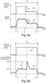
- Fig. 6a
- shows, by way of example, a current signal which correlates with a process indicator signal, and
- Fig. 6b
- shows, by way of example, a current signal, which exhibits anomalous behavior.
- Referring to
Fig. 1 , anaerosol measurement system 1000 may be arranged to measure aerosol particles P1 of a primary gas PG0. The primary gas PGO may carry aerosol particles P1, which may be generated by an aerosol particle source SRC1. The source SRC1 may be e.g. a combustion facility or a chemical plant. The source SRC1 may be e.g. a heating boiler, an oil burner, a gas burner, a pulverized coal burner, an incineration furnace, a fluidized bed boiler, an internal combustion engine, a gas turbine, or an oil refinery. The primary gas PGO may carry aerosol particles P1. The particles P1 may be e.g. solid or liquid particles. The size of the aerosol particles P1 may be e.g. in the range of 5 nm to 50 µm. The input gas flow FG0 containing the particles P1 may also be called as the input aerosol flow FG0. - The primary gas PG0 may be guided or contained in a gas duct DUC1. The gas duct DUC1 may be e.g. a flue gas duct of a combustion facility. The gas duct DUC1 may be e.g. an exhaust gas duct. The primary gas PG0 may also be ambient gas, in particular ambient air. The ambient gas may be guided by the gas duct DUC1. Alternatively, the duct may be omitted, i.e. ambient gas may be sampled directly without using the duct DUC1. The
system 1000 may comprise asampling nozzle 612 for separating an aerosol sample flow FG0 from the primary gas PG0. The orifice of thesampling nozzle 612 may be located at a sampling point POS0. Theaerosol measurement system 1000 may comprise asampling line 610 to guide an aerosol sample flow FG0 from the gas duct DUC1 to the measuringapparatus 500. The aerosol sample flow FG0 may also be called e.g. as an input flow FG0. - The
aerosol measurement system 1000 may comprise anaerosol measuring apparatus 500, which may be arranged to continuously monitor the particles P1 of the primary gas PG0. The sample gas flow FG0 may be separated from the primary gas PG0 e.g. by using asampling nozzle 612. The sample flow FG0 may be guided to theaerosol measuring apparatus 500 via asampling line 610. The flow FG2 denotes an input flow guided to themonitoring device 200. The concentration of aerosol particles P1 carried by the flow FG2 may be proportional to the concentration of aerosol particles P2 in the primary gas PG0. The flow FG2 may be e.g. separated from the sample flow FG0 and/or the input flow FG2 may be formed from the sample flow FG0 by diluting the sample flow FG0.The sample flow FG0 may also be directly guided to themonitoring device 200 as the input flow FG2. - The
particle monitoring device 200 may comprise a charging unit CUNIT1 to form charged particles P2 by charging the aerosol particles P1. Theapparatus 500 may comprise avoltage supply 410 to provide operating power for the charging unit CUNIT1. Themonitoring device 200 may comprise a detector DET1 to detect the charge carried by the charged particles P2. The detector DET1 may provide an electric current Ip(t), which may be substantially proportional to the charge of the charged particles captured by the detector DET1 per unit time. Theapparatus 500 may comprise a current monitoring unit CMU1 to measure the electric current Ip(t). The current monitoring unit CMU1 may comprise e.g. an electrometer for measuring the magnitude of the electric current lp(t) conducted from the detector DET1 to the current monitoring unit CMU1. The magnitude of the electric current lp(t) may be indicative of the instantaneous active surface area concentration of aerosol particles captured by the detector DET1. The electric current lp(t) may be interpreted to carry a signal, which comprises information about the concentration. The electric current lp(t) may also be called as the electric current signal lp(t). The electric current signal lp(t) may be sent from the detector DET1 to the current monitoring unit CMU1. - The current monitoring unit CMU1 may substantially continuously provide a monitoring signal S1(t) based on the electric current lp(t) obtained from the detector DET1. The current monitoring unit CMU1 may provide e.g. a digital monitoring signal S1(t) based on the measured electric current lp(t). The
monitoring device 200 may provide a monitoring signal S1(t) which is indicative of the instantaneous concentration of aerosol particles carried by the flow FG2. - The monitoring signal S1(t) may also be indicative of the instantaneous concentration of aerosol particles carried by the sample flow FG0. The monitoring signal S1(t) may also be indicative of the instantaneous concentration of aerosol particles in the primary gas PG0. The concentration of aerosol particles carried by the flow FG2 may be proportional to the concentration of aerosol particles carried by the flow FG0. The dimensions of the
sampling nozzle 612 and the gas flow rates of the flows FG0, FG2 may be selected such that the concentration of aerosol particles P1 carried by the flow FG2 is substantially equal to the concentration of aerosol particles in the primary gas PG0. The dimensions of thesampling nozzle 612 and the gas flow rates of the flows FG0, FG2 may be selected such that the size distribution of aerosol particles P1 carried by the flow FG2 is substantially equal to the concentration of aerosol particles in the primary gas PG0. - The
apparatus 500 may be considered to be a first measuring instrument. Theaerosol measurement system 1000 may optionally comprise one or more additional measuringinstruments 100, e.g. a gas analyzer unit and/or a filter unit. Thefilter unit 100 may comprise a filter FIL1. Thefilter unit 100 may be arranged to capture particles P1 of the primary gas PG0 e.g. for gravimetric measurement of the mass concentration of the particles P1. The chemical composition of the captured particles may be determined by chemical analysis. For example, the structure of the captured particles may be determined by using a scanning electron microscope (SEM) or by using a transmission electron microscope (TEM). Theanalyzer unit 100 may be arranged to analyze e.g. the chemical composition of the primary gas PG0. Theanalyzer unit 100 may be arranged to analyze e.g. the concentration of a gaseous component of the primary gas PG0. Theaerosol measurement system 1000 may optionally comprise a pump PUMP1 for drawing a gas flow FG1 through theadditional measuring instrument 100. - The
system 1000 may optionally comprise adistributor 300 to separate the gas flow FG1 and/or the gas flow FG2 from the sample flow FG0. The gas flow FG2 may be guided to themonitoring device 200. The flow FG1 may be guided to anadditional measuring instrument 100. The flow FG0 may have a flow rate Q0. The flow FG1 may have a flow rate Q1. The flow FG2 may have a flow rate Q2. The flow rate Q0 may be equal to the sum Q1+Q2. The detector DET1 of themonitoring device 200 may provide an electric current lp(t), which is indicative of the concentration of the aerosol particles P1 carried by the gas flow FG2. The detector DET1 of themonitoring device 200 may provide an electric current lp(t), which is indicative of the concentration of the aerosol particles P1 carried by the input gas flow FG0. - The
aerosol measuring apparatus 500 may optionally comprise a pump PUMP2 for drawing the gas flow FG2 through theparticle monitoring device 200. Theaerosol measuring apparatus 500 may optionally comprise avalve 280 for controlling the gas flow FG2. The pump PUMP2 may be positioned downstream of the detector DET1 so that the pump PUMP2 does not remove particles from the gas flow FG2 before the particles P2 are detected by the detector DET1. The pump PUMP2 may be e.g. a diaphragm pump, a piston pump, a rotary vane pump, or a peristaltic pump. The gas flow FG2 guided through themonitor device 200 may be vented e.g. into the atmosphere or into a ventilation duct. After the flow FG2 has been drawn through the pump PUMP2, the flow FG2 may be discharged from anoutlet 290 e.g. into the ambient air outside theapparatus 500, or into a ventilation duct. - The
apparatus 500 may optionally comprise thevalve 280 for controlling the flow rate Q2 of the gas flow FG2. Thevalve 280 may be e.g. a controllable magnetic valve. Thevalve 280 may be positioned downstream of the detector DET1. - The
device 200 may be optionally kept e.g. in a heated oven e.g. in order to stabilize condensation. - The
aerosol measuring apparatus 1000 may optionally comprise a dilution system for diluting the sample flow FG0. The dilution ratio may be determined and/or adjusted based on analysis of the signal S1(t) obtained from themonitoring unit 200. The dilution ratio may be controlled based on the current signal lp(t). The dilution ratio may be increased if analysis of the current signal lp(t) indicates that the concentration is too low. The dilution ratio may be decreased if analysis of the current signal lp(t) indicates that the concentration is too high. The dilution ratio may be adjusted during a particle collecting period based on the current signal lp(t). The dilution ratio may be set to a determined value before the start of a particle collecting period, based on the current signal lp(t). - The aerosol particle source SRC1 may optionally provide a process indicator signal P(t). The monitor signal S1(t) may be compared with the process indicator signal P(t) in order to determine whether a change of an operating parameter of the particle source SRC1 corresponds to a change of the monitor signal S1(t). The monitor signal S1(t) may be compared with the process indicator signal P(t) in order to determine whether the monitor signal S1(t) correlates with the process indicator signal P(t). The process indicator signal P(t) may be e.g. indicative of fuel flow rate, input air flow to a combustion facility, an operating temperature of the source SRC1, operating temperature of a catalytic converter, operating temperature of a filter, operating temperature of a process, fuel feeding pressure, or a flow rate of an additive. The aerosol particle source SRC1 may simultaneously provide a plurality of process indicator signals, which may be indicative of different operating parameters of the source SRC1.
-
Fig. 2 shows, by way of example, a control system of theparticle measuring apparatus 500. Theapparatus 500 may comprise a control unit CNT1 for processing measured data and/or for controlling operation of theapparatus 500. Theapparatus 500 may comprise the pump PUMP2 to draw the flow FG2 through themonitor device 200. Theapparatus 500 may optionally comprise avalve 280 to control the flow FG2. - The
apparatus 500 may comprise the detector DET1 for providing the electric current signal lp(t). Theapparatus 500 may comprise the current monitoring unit CMU1 to provide the monitor signal S1(t) from the current signal lp(t). Theapparatus 500 may comprise a memory MEM1 for storing measured data DATA1. The data DATA1 may comprise e.g. the measured signal lp(t) and/or S1(t). - The
apparatus 500 may comprise a memory MEM2 for storing computer program PROG1. The computer program PROG1 may comprise computer program code configured to, when executed on at least one data processor, cause the control unit CNT1 to control operation of theapparatus 500. The computer program PROG1 may comprise computer program code configured to, when executed on at least one data processor, cause processing of measured data lp(t), S1(t). - The
apparatus 500 may optionally comprise a communication unit RXTX1 for receiving and/or transmitting data. The communication unit RXTX1 may transmit e.g. the monitoring signal S1(t) e.g. to an external portable computer. The communication unit RXTX1 may transmit e.g. the monitoring signal S1(t) e.g. to a control unit of thesystem 1000. The communication unit RXTX1 may transmit e.g. the monitoring signal S1(t) e.g. to an Internet server. The communication unit RXTX1 may receive and/or transmit data e.g. by using wireless transmission, by using an optical cable and/or by using an electric cable. A command for starting and/or a command for stopping a measurement may be communicated via the communication unit RXTX1 to the control unit CNT1. The computer program PROG1 may be updated by receiving data via the communication unit RXTX1. The computer program PROG1 may be updated by receiving data e.g. from an Internet server. - The
apparatus 500 may optionally comprise a clock CLK1 to provide time information. The monitoring signal S1(t) may be recorded in the memory MEM1 as data DATA1 such that the recorded monitoring signal S1(t) is associated with the time information. The monitoring signal S1(t) may be recorded in the memory MEM1 as a function S1(t) of time t. The data DATA1 may be time-stamped. - The
apparatus 500 may optionally comprise a user interface UIF1 for providing information to a user and/or for receiving user input from a user. The user interface UIF1 may comprise e.g. a display and one or more keys. The user interface UIF1 may comprise e.g. a touch screen. The user interface UIF1 may be arranged to display e.g. the magnitude of the electric current lp(t). The interface UIF1 may be arranged to provide visual indication of the magnitude of the electric current (IP(t)). The interface UIF1 may be arranged to display e.g. a curve, which indicates the magnitude of the electric current (IP(t)). - The
monitoring device 200 may be positioned e.g. in a heated cabinet and/or close to a hot combustion facility. The interface UIF1 may also be remote from thedevice 200 e.g. so that the interface UIF1 may be located at an ergonomic and/or safe position. A portable computer or a mobile device (e.g. a smartphone) may be arranged to communicate with theapparatus 500 via the communication unit RXTX1, and said portable computer or mobile device may be arranged to operate as the interface UIF1. - Data measured by the
device 200 may also be processed in a distributed manner. For example, temperature compensation, compensation of a background and/or data correlation analysis may be performed in a separate data processor. The data may be processed e.g. by a portable computer and/or by using an internet server. - The
apparatus 500 may optionally comprise a rechargeable battery BAT1 e.g. for providing operating power e.g. for one or more of the following parts: the control unit CNT1, thehigh voltage supply 410, the charge monitoring unit CMU1, and/or the pump PUMP2. Thanks to using the battery, theapparatus 500 does not need to be connected to an electric power line during operation of theapparatus 500. After the particle collecting period, theapparatus 500 may be disconnected from thesample line 610, and moved to a location, which is remote from thesample line 610. The battery may be recharged at a location, which is remote from thesampling line 610. - The
apparatus 500 may comprise ahigh voltage supply 410 for providing operating voltage Uc to the corona electrode ELEC3. Theapparatus 500 may be arranged to control operation of thehigh voltage supply 410. - The
apparatus 500 may optionally comprise one or more heating elements HUNIT1. The heating element HUNIT1 may be arranged to stabilize the operating temperature of the current monitoring unit CMU1. The heating element HUNIT1 may be arranged to keep the operating temperature of the current monitoring unit CMU1 substantially constant. - The
apparatus 500 may comprise a flow sensor SEN2 to monitor the flow rate of the flow FG2 and/or to monitor the pressure difference of the detector DET1. The flow resistance of the detector DET1 may increase during operation due to particles captured to the filter DFIL. The flow rate Q2 of the flow FG2 may depend on the flow resistance of the detector DET1. Theapparatus 500 may comprise a sensor SEN2 for monitoring the pressure difference caused by the detector DET1. The sensor SEN2 may be e.g. a pressure sensor, which measures the pressure downstream the detector DET1. The sensor SEN2 may be e.g. a pressure difference sensor, which measures the pressure difference over the detector DET1. The sensor SEN2 may be e.g. a flow sensor, which may be arranged to monitor the flow rate Q2 of the flow FG2. The operation of the sensor SEN2 may be based on e.g. monitoring pressure difference or a change of temperature caused by the flow FG2. - The
apparatus 500 may be arranged to detect when the flow resistance of the detector DET1 exceeds a predetermined limit. The detector DET1 may be replaced or cleaned if the flow resistance of the detector DET1 exceeds the predetermined limit. Theapparatus 500 may be arranged to provide an indication to a user when the flow resistance of the detector DET1 exceeds a predetermined limit. The indication may be provided e.g. by using the user interface UIF1. - The
apparatus 500 may be arranged to control the pump PUMP2 based on a signal obtained from the sensor SEN2 so as to keep the flow rate Q2 in a predetermined range. For example, theapparatus 500 may be arranged to adjust a rotation speed of a motor of the pump PUMP2 based on a signal obtained from the sensor SEN2. - An abnormal situation of a process or combustion facility may be associated with a sudden increase of aerosol concentration. The operation of the
aerosol measurement system 1000 may be controlled based on the monitoring signal provided S1(t) by themonitor unit 200. For example, theaerosol measurement system 1000 may be arranged to start a gas flow FG1 though a particle collectingfilter unit 100 when the monitoring signal S1(t) exceeds a predetermined level, or when the rate of change of the monitoring signal S1(t) exceeds a predetermined level. Consequently, a particle sample may be collected by thefilter unit 100, and the monitoring signal S1(t) may be recorded for subsequent analysis of the abnormal situation. Theapparatus 500 may be configured to send a control signal for starting and/or stopping the gas flow FG1. The control signal may be sent e.g. via the communication unit RXTX1. - The charging unit CUNIT1 may be arranged to operate such that the corona discharge is switched on only when the flow rate Q2 through the charging space SPC1 is greater than a predetermined limit. The charging unit CUNIT1 may be arranged to operate such that the corona discharge is switched off when the gas flow rate Q2 of the gas flow FG2 decreases below the predetermined limit. The
voltage supply 410 may be controlled based on the flow rate Q2 of the flow FG2. - The monitoring signal S1(t) may drift e.g. due to a change of operating temperature of the current monitoring unit CMU1, due to erosion of a corona electrode ELEC3 and/or due to contamination of the flow channels. The
apparatus 500 may be arranged to at least partly compensate the effect of temperature, erosion and/or contamination on the monitoring signal S1(t). - The operating temperature of the
monitoring device 200 may have an effect on the monitoring signal. In particular, a change of the operating temperature of the current monitoring unit CMU1 may cause a change of the monitoring signal even when the particle flow to themonitoring device 200 remains unchanged. Theapparatus 500 may be arranged to stabilize the operating temperature of the current monitoring unit CMU1. Theapparatus 500 may be arranged to monitor the operating temperature of themonitoring device 200. Theapparatus 500 may optionally comprise a temperature sensor SEN3 for monitoring the operating temperature TEMP200 of the current monitoring unit CMU1. Theapparatus 500 may comprise a heating element HUNIT1 arranged to heat the current monitoring unit CMU1. Theapparatus 500 may be arranged to control the heating element HUNIT1 e.g. based on temperature information TEMP200 obtained from the temperature sensor SEN3. - The
voltage supply 410 may feed electric power to the corona electrode ELEC3. Thevoltage supply 410 and the corona discharge DSR1 may convert electric power into heat. The current monitoring unit CMU1 may be located close to thevoltage supply 410 and/or close to the corona electrode ELEC3. The operation of thevoltage supply 410 and the corona discharge DSR1 may have an effect on the operating temperature of the current monitoring unit CMU1. The corona discharge DSR1 may have a first operating state where the corona discharge DSR1 is operating, and a second operating state where the corona discharge DSR1 is not operating. Thevoltage supply 410 may have a first active operating state where the corona discharge DSR1 is operating, and a second inactive operating state where the corona discharge DSR1 is not operating. Theapparatus 500 may comprise a heating element HUNIT1 arranged to heat the current monitoring unit CMU1. Theapparatus 500 may be arranged to control the heating element HUNIT1 based on the operating state of the corona discharge. Theapparatus 500 may be arranged to control the heating element HUNIT1 based on the operating state of thevoltage supply 410. Theapparatus 500 may be arranged to control the heating element HUNIT1 so as to keep the electric power consumption of themonitoring device 200 substantially constant when the operating state of thevoltage supply 410 is changed. Thevoltage supply 410 may have a first heating power, the corona discharge DSR1 may have a second heating power, and the heating element HUNIT1 may have a third heating power. Theapparatus 500 may be arranged to control the heating element HUNIT1 so as to keep the sum of said heating powers substantially constant when the operating state of thevoltage supply 410 is changed. - The
apparatus 500 may be arranged to compensate an effect of the operating temperature on the monitoring signal based on temperature information obtained from the temperature sensor SEN3. Theapparatus 500 may be arranged to provide a temperature-compensated monitoring signal S1(t). Theapparatus 500 may comprise a memory, which comprises predetermined temperature compensation data. Theapparatus 500 may be arranged to provide a temperature-compensated monitoring signal S1(t) from the current lp(t) by using information about the measured operating temperature and by using the temperature compensation data. - In an embodiment, a plurality of
identical monitoring devices 200 may be manufactured. The temperature compensation data may be determined separately for eachindividual monitoring device 200. Eachindividual monitoring device 200 may be associated with temperature compensation data associated with saidmonitoring device 200. Temperature compensation data associated with afirst monitoring device 200 may be different from temperature compensation data associated with asecond monitoring device 200. When afirst monitoring device 200 is replaced with asecond monitoring device 200, the temperature compensation data associated with thesecond monitoring device 200 may be stored in the memory of theapparatus 500. The temperature compensation data may be e.g. retrieved from an Internet server based on an identification code of thesecond monitoring device 200. Thesecond monitoring device 200 may also comprise a memory for storing the pre-determined temperature compensation data associated with thesecond monitoring device 200. The temperature compensation data also may be inputted to a memory of theapparatus 500 manually by using a user interface UIF1. - The monitoring signal S1(t) provided by the
device 200 may be compensated e.g. by using a background signal value SREF. The background signal value SREF may be determined experimentally e.g. by measuring the electric current signal lp(t) of the detector DET1 in a situation where the flow FG2 through the detector DET1 is zero. The flow FG2 may be reduced to zero e.g. by closing thevalve 280. The flow rate Q2 of the flow FG2 is greater than zero during normal operation. A compensated monitoring signal S1(t) may be determined from the electric current signal lp(t) measured during the normal operation by using the background signal value SREF. Theapparatus 500 may be arranged to determine a compensated monitoring signal S1(t) from the electric current signal lp(t) measured during the normal operation by using the background signal value SREF. - The
apparatus 500 may be arranged to measure a first background signal value SREF1 by measuring the electric current Ip(tR1) at a first time tREF1 when that the flow FG2 is substantially equal to zero. Theapparatus 500 may be arranged to measure a second reference value SREF2 at a second time tREF2 when that the flow FG2 is substantially equal to zero. The time tREF1 may be e.g. before the start of a particle colleting period Ttot, and the time tREF2 may be after the end of a particle collecting period Ttot. The background signal value SREF2 may also be different from the background signal value SREF1. - A compensated monitoring signal S1(t) may be determined from the electric current signal lp(t) measured during the normal operation by using the background signal values SREF1 and SREF2.
- ΔSREF denotes the change between the signals SREF1, SREF2. (i.e. ΔSREF = SREF2 - SREF1). The validity of the electric current signal lp(t) measured during normal operation may be evaluated based on the change ΔSREF. The electric current signal lp(t) may be determined to be valid if the change ΔSREF is smaller than a predetermined limit. The electric current signal lp(t) may be determined to be invalid if the change ΔSREF exceeds the predetermined limit.
- The
apparatus 500 may be configured to determine the compensated monitoring signal S1(t) from the measured electric current signal lp(t) by using one or more background signal values SREF1, SREF2 and/or by using temperature information. - An external data processing device may be configured to determine the compensated monitoring signal S1(t). In particular, a portable computer may be configured to determine the compensated monitoring signal S1(t) from the measured electric current signal lp(t) by using one or more background signal values SREF1, SREF2 and/or by using temperature information.
- The compensated monitoring signal S1(t) may be determined substantially in real time or after the end of the particle collecting time period Ttot. The current monitoring unit CMU1 may provide auxiliary signal data SAUX(t), which may be indicative of the instantaneous magnitude of the electric current lp(t). The compensated monitoring signal S1(t) may be subsequently determined from the auxiliary signal data SAUX(t) by using information about the background signal values SREF1, SREF2. The auxiliary signal data SAUX(t) may be optionally recorded in a memory, and the compensated monitoring signal S1(t) may be determined from the auxiliary signal data SAUX(t) after the end of the particle collecting time period Ttot.
-
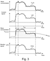
Fig. 3 illustrates, by way of example, formation of the measured signals. - The uppermost curve of
Fig. 3 shows, by way of example, the temporal evolution of the concentration Cp(t) of aerosol particles of the input flow FG0. Cp(t) denotes the actual mass concentration. The aim of the particle measurement may be to provide one or more measured values, which represent the actual mass concentration Cp(t). - The second curve from the top of
Fig. 3 shows the temporal evolution of the electric current lp(t). The electric current lp(t) may be substantially proportional to the active surface area concentration of the aerosol particles of the input flow FG0. To the first approximation, the temporal variations of the active surface area concentration may provide an estimate for the temporal variations of the mass concentration Cp(t). - The electric current lp(t) may also depend on the flow rate Q2 of the flow FG2. The electric current lp(t) may be substantially proportional to the flow rate Q2.
- Referring to the third curve from the top of
Fig. 3 , the aerosol particles may be collected by a filter FIL1. The flow FG1 through the filter FIL1 may be started at a time t1 and stopped at the time t2. The time period Ttot may denote the time period between the times t1 and t2. The total mass mtot of the particles collected by a filter FIL1 during the time period Ttot may be measured by weighing the filter FIL1 after the measurement period Ttot. The total mass mtot may be substantially equal to the integral of the product Q1(t)·Cp(t) over the time period Ttot. The average concentration Cave,tot representing the whole time period Ttot may be determined by dividing the total mass mtot by the total gas volume Vtot guided through the filter FIL1 during the time period Ttot. - The lowermost curve of
Fig. 3 shows the monitoring signal S1(t) determined from the electric current lp(t). The monitoring signal S1(t) may be indicative of the electric current lp(t). The monitoring signal S1(t) may be substantially proportional to the electric current lp(t). - An instantaneous concentration value C1(t) may be determined from the average concentration Cave,tot by using the measured current signal lp(t).
- An estimate C1(tk) for the instantaneous concentration Cp(tk) at a time tk may be determined from the average concentration Cave,tot by using the measured electric current Ip(t):

- The equation (1) may be used for interpolation, i.e. the time period Ttot may comprise the time tk. The equation (1) may provide a proportionality constant for calculating the estimate C1(tk) of the instantaneous concentration Cp(tk) from the instantaneous current value Ip(tk). In an embodiment, an estimate C1(tk) of the instantaneous concentration Cp(tk) may be calculated by using said proportionality constant also when the time period Ttot from the time t1 to the time t2 does not comprise the time tk. In other words, the estimate C1(tk) may also be calculated by extrapolation.
- The monitoring signal S1(t) may be substantially proportional to the electric current signal lp(t). The electric current signal lp(t) appearing in equation (1), be replaced with the monitoring signal S1(t).
- Referring to
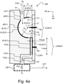
Fig. 4a , themonitoring device 200 may comprise a charging unit CUNIT1 and a charge detector DET1. The charging unit CUNIT1 may provide charged particles P2 by charging at least a part of the particles P1 carried by the flow FG2. The charging unit CUNIT1 may convert at least a part of the particles P1 of the flow FG2 into charged particles P2. The charging unit CUNIT1 may comprise a corona electrode ELEC3 and a counter electrode ELEC0 for generating ions J1 by a corona discharge DSR1. The ions J1 may form charged particles P2 by exchanging charge with neutral aerosol particles P1. The corona electrode ELEC3 may operate together with the counter-electrode ELEC0. The electrodes ELEC3, ELEC0 may be connected to thehigh voltage supply 410 such that the electrodes ELEC3, ELEC0 have a voltage difference Uc-U0. The corona electrode ELEC3 and the counter-electrode ELEC0 may together form an electric field EF0, which generates the corona discharge DSR1 (Fig. 4c ). The strength of the electric field EF0 may locally exceed the dielectric strength of the gas guided through the charging space between the electrodes ELEC0, ELEC3 so that the corona discharge DSR1 may be formed in the vicinity of the corona electrode ELEC3. - The corona electrode ELEC3 and the counter-electrode ELEC0 may together define a substantially hemispherical charging space SPC1. The charging space SPC1 may also be called e.g. as the charging volume or as the charging zone. The gas flow FG2 and neutral particles P1 may be guided into the charging space SPC1 via an inlet channel CH1. The gas flow FG2 and charged particles P2 may be guided from the charging space SPC1 via an outlet channel CH2.
- The counter-electrode ELEC0 may be substantially hemispherical. The counter-electrode ELEC0 may have a surface portion, which is substantially hemispherical. The counter-electrode ELEC0 may have a substantially spherical surface to define a hollow half of a sphere. The corona electrode ELEC3 may be a conductive element which has an exposed sharp tip. The tip of the corona electrode ELEC3 may be located at an axis of symmetry of the hemispherical charging space SPC1. The distance between the tip and each point of the hemispherical portion of the electrode ELEC0 may be substantially equal to R1. The charging of the particles may take place in the charging space SPC1 between the corona electrode ELEC3 and the counter-electrode ELEC0.
- The shape of the corona electrode ELEC3 may change during operation due to electrode erosion. The substantially hemispherical charging space SPC1 may provide a symmetric electric field, which in turn may facilitate maintaining the symmetrical shape of the corona electrode ELEC3 during operation. The substantially hemispherical charging space SPC1 may reduce or minimize electrical power needed for generating the corona discharge. The hemispherical charging space may e.g. reduce the effect of a change of temperature on the degree of charging of the particles. The hemispherical charging space may e.g. reduce the effect of a change of gas flow rate on the degree of charging of the particles. The hemispherical charging space may help to provide sufficient gas velocity in the vicinity of the surfaces of the charging space, so as to minimize deposition of particles to said surfaces. The particles may travel through the charging space SPC1 along different paths. A first path may be close to the corona electrode ELEC3. A second path may be close to the counter electrode ELEC0. The density of ions J1 close to the corona electrode ELEC3 may be higher than the density of ions J1 close to the counter electrode ELEC0. The hemispherical shape may reduce the residence times of the particles in the charging space SPC1. The hemispherical shape may facilitate providing a fast response time.
- Particles traveling along the first path may have a shorter residence time in the charging space SPC1 but they may be exposed to a higher ion density. Particles traveling along the second path may have a second longer residence time in the charging space SPC1 but they may be exposed to a lower ion density. Thus, the hemispherical shape may reduce the effect of the different paths on the final degree of charging of the charged particles P2.
- The counter-electrode ELEC0 may be substantially impermeable to the gas in order to define the gas flow passing through the charging space SPC1. The counter-electrode ELEC0 may be substantially impermeable to the gas of the gas flow FG2 in order to ensure that substantially all particles of the gas flow FG2 pass from the channel CH1 to the channel CH2 through the charging space SPC1. The outlet channel CH2 may be e.g. substantially parallel with the inlet channel CH1.
- The counter-electrode ELEC0 may have an inner radius R1. The substantially hemispherical portion of the counter-electrode ELEC0 may comprise an opening APE1 for guiding the flow FG2 from the inlet channel CH1 to the charging space SPC1. The substantially hemispherical counter-electrode ELEC0 may define the opening APE1 for guiding the flow FG2 from the inlet channel CH1 to the charging space SPC1. The flow FG2 may pass from the inlet channel CH1 to the charging space SPC1 via the opening APE1 of the counter-electrode ELEC0. The dimension h1 may denote the distance between the opening APE1 and the planar portion of the boundary of the hemispherical charging space SPC1. The distance h1 may be e.g. greater than 0.3 times the inner radius R1 in order to prevent a straight travel path of particles through the charging space SPC1.
- The corona electrode ELEC3 may have a substantially sharp tip. The radius of curvature of the tip may be e.g. smaller than 0.2 mm. The distance between the tip of the corona electrode ELEC3 and the counter-electrode ELEC0 may be substantially equal to R1.
- The
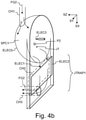
monitoring unit 200 may comprise the ion trap JTRAP1 to remove ions J1 from the flow FG2. The gas flow FG2, the charged particles P2, and the ions J1 may be guided from the charging space SPC1 into the ion trap JTRAP1. The ion trap JTRAP1 may be located between the charging space SPC1 and the detector DET1. The gas flow FG2 and the charged particles P2 may be guided from the ion trap JTRAP1 to the detector DET1. The ion trap JTRAP1 may be positioned downstream of the charging unit CUNIT1 and upstream of the detector DET1. The ion trap JTRAP1 may remove at least a part of the ions J1 from the flow FG2, which is guided to the detector DET1. Using the ion trap JTRAP1 may stabilize the electric current lp(t). The ion trap JTRAP1 may comprise a first deflecting electrode ELEC1 and a second deflecting electrode ELEC2. The deflecting electrodes ELEC1, ELEC2 may together form an electric field, which deflects at least part of the ions J1 away from the gas flow FG2. dTRAP may denote the distance between the electrodes ELEC1, ELEC2. LTRAP may denote the length of the ion trap JTRAP1. The electric field may be substantially transverse with respect to the direction of the gas flow FG2 passing through the electrodes ELEC1, ELEC2. The ion trap may comprise e.g. a pair of substantially parallel electrodes ELEC1, ELEC2. - The radial distance R1 between the electrodes ELEC3, ELEC0 may be e.g. in the range of 1 mm to 50 mm, advantageously in the range of 2 mm to 20 mm, and preferably in the range of 3 mm to 10 mm. Using a small distance R1 may provide more effective charging of the particles P2. The voltage difference Uc-U0 applied between the electrodes ELEC3, ELEC0 may be reduced when using a small distance R1. However, the charging space SPC1 may be clogged or short-circuited by a particle P2 if the distance R1 is very small.
- The distance dTRAP between the deflecting electrodes ELEC1, ELEC2 may be e.g. in the range of 0.1 mm to 2 mm, advantageously in the range of 0.2 mm to 1.0 mm, and preferably in the range of 0.3 mm to 0.8 mm. The distance dTRAP may be e.g. smaller than 20% of the radius R1. The voltage difference U2-U1 applied between the deflecting electrodes ELEC1, ELEC2 may be reduced when using a small distance dTRAP. However, the channel CH2 may be clogged or short-circuited by a particle P2 if the distance dTRAP is very small. The length LTRAP may be e.g. in the range of 2 mm to 50 mm.
- The deflecting electrodes ELEC1, ELEC2 may be e.g. substantially planar. The deflecting electrodes ELEC1, ELEC2 may together define a flow channel CH2. The flow channel CH2 may receive the gas flow FG2, charged particles P2, and ions J1 from the charging space SPC1.The input of the flow channel CH2 may be located close to the charging space SPC1. The input of the flow channel CH2 may be located close to a planar portion of the hemispherical charging space SPC1. The distance between the electrode ELEC2 and the corona electrode ELEC3 may be e.g. smaller than 1.2 times the radius R1.
- The gas flow FG2 and the charged particles P2 may be guided from the ion trap JTRAP to the particle detector DET1 via a channel CH3. The particle detector DET1 may provide the electric current signal lp(t), which may be substantially equal to the charge captured by the particle detector DET1 per unit time.
- The counter-electrode ELEC0 and/or the deflecting electrode ELEC1 may be at the same electric potential. The counter-electrode ELEC0 and/or the deflecting electrode ELEC1 may be at the ground potential U0. The deflecting electrode ELEC1 may be galvanically connected to the counter-electrode ELEC0. The counter-electrode ELEC0 and/or the deflecting electrode ELEC1 may be implemented on the surface of a body BLCO. The counter-electrode ELEC0 and/or the deflecting electrode ELEC1 may be implemented on the surface of a conductive body BLC0. The counter-electrode ELEC0 and/or the deflecting electrode ELEC1 may be formed e.g. from a single metal block by mechanical machining. The counter-electrode ELEC0, the deflecting electrode ELEC1, the inlet channel CH1, and the outlet channel CH2 may be formed from a single metal block by mechanical machining. This may provide an extremely rugged and stable structure. The counter-electrode ELEC0 and/or the deflecting electrode ELE3 may also be formed e.g. by molding or 3D printing. The counter-electrode ELEC0 and/or the deflecting electrode ELE3 may be formed e.g. by depositing conductive material on electrically insulating material.
- The corona electrode ELEC3 and/or the deflecting electrode ELEC2 may be supported by a supporting element CVR1. The supporting element CVR1 may be electrically insulating. The supporting element CVR1 may also be called e.g. as the cover of the charging space SPC1. The electrode ELEC0 and/or ELEC1 may be galvanically connected to a contact surface N1. The corona electrode ELEC3 may be galvanically connected to a contact element N3. The deflecting electrode ELEC2 may be galvanically connected to a contact element N2. The electrodes ELEC2, ELEC3 may be on a first side of the cover CVR1, and the elements N2, N3 may be on a second side of the cover CVR1. The elements N2, N3 may also extend through the cover CVR1 from the first side to the second side. The elements N3, N2 may be e.g. metallic stubs. The planar surface of the electrically insulating cover CVR1 may partly define the hemispherical form of the charging space SPC1. The cover CVR1 may have a substantially planar surface, which may partly define the charging space SPC1. The substantially planar surface of the cover CVR1 may partly define the hemispherical charging space SPC1.
- The cover CVR1 may also support the deflecting electrode ELEC2. A planar surface of the cover CVR1 may support the deflecting electrode ELEC2. The deflecting electrode ELEC2 may be substantially parallel with the planar portion of the charging space SPC1. The electrode ELEC2 may be implemented e.g. by depositing conductive material on the surface of the cover CVR1, or by attaching a conductive foil on the surface of the cover CVR1.
- The planar surface of the deflecting electrode ELEC2 may partly define the flow channel CH2. The cover CVR1 may form a pressure-tight seal together with the body BLCO. The cover CVR1 may electrically insulate the corona electrode ELEC3 from the conductive body BLCO. The cover CVR1 may electrically insulate the deflecting electrode ELEC2 from the conductive body BLCO.
- Using the planar electrodes ELEC1, ELEC2 may provide a simple and rugged structure. In an embodiment, the ion trap JTRAP may also be implemented by using non-planar electrodes ELEC1, ELEC2, e.g. by using a pair of concentric electrodes. The electrodes ELEC1, ELEC2 may be e.g. concentric cylindrical electrodes.
- SX, SY and SZ denote orthogonal directions.
-
Fig. 4b shows, in a three dimensional view, the hemispherical charging space SPC1 and the ion trap JTRAP1. - Referring to
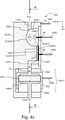
Figs. 4c and4e , the particle detector DET1 may comprise a particle filter DFIL surrounded by a Faraday cage FARA1. The Faraday cage FARA1 may be supported by one or moreelectrical insulators electrical insulators electrical insulators electrical insulators conductive shell 253. Theconductive shell 253 may form a part of the Faraday cage FARA1. The particle filter DFIL may be electrically insulating or electrically conductive. The particles P2 may be captured by the particle filter DFIL. - The
particle monitoring apparatus 500 may comprise one or more connecting elements PIN1, PIN2, PIN3, PIN4 for forming a galvanic connection with the electrodes ELEC0, ELEC1, ELEC2, ELEC3, and the detector DET1. The element PIN1 may form a galvanic contact with the electrodes ELEC0 and ELEC1. The element PIN2 may form a galvanic contact with the electrode ELEC2. The element PIN3 may form a galvanic contact with the corona electrode ELEC3. The element PIN4 may form a galvanic contact with the Faraday cage FARA1 of the detector DET1. The element PIN1 may be arranged to contact the contact element N1. Also portion of the surface of the body BLC0 may operate as the contact element N1. The element PIN2 may be arranged to contact the contact element N2. The element PIN3 may be arranged to contact the contact element N3. The connecting element PIN4 may be arranged to contact the detector DET1. The connecting elements PIN2, PIN3, PIN4 may be e.g. spring-loaded conductive pins. -
Fig. 4d shows a cross-section of theparticle monitoring device 200 along the line A-A shown inFig. 3 a. POS3 denotes the position of the corona electrode ELEC3. POS2 denotes the position of a contact element N2. POS4 denotes the position of a connecting element PIN4. B_CH2 denotes the position of the flow channel CH2. B_ELEC2 denotes the position of the deflecting electrode ELEC2. -
Fig. 5 e shows a detector DET1 when it has been separated from thedevice 200. The detector DET1 may comprise e.g. a particle filter DFIL for capturing the charged particles P2. The filter DFIL may be electrically conductive or electrically insulating. The filter DFIL may be surrounded by a Faraday cage FARA1, or an electrically conductive outer layer of the filter DFIL may operate as the Faraday cage FARA1. An electrically conductive filter DFIL may comprise e.g. sintered conductive particles or conductive fibers. The Faraday cage FARA1 and/or the conductive filter DFIL may be galvanically connected to the current monitoring unit CMU1. The charge carried by charged particles P2 may be detected by using the Faraday cage FARA1 and the current monitoring unit CMU1 also in a situation where the charged particles P2 captured by the filter DFIL inside the Faraday cage FARA1 do not touch the Faraday cage FARA1. - The filter DFIL may collect particles irreversibly such that the particles are not released from the detector DET1 back into the gas flow. The detector DET1 may collect particles during the measurement period such that e.g. less than 10% of the mass of the collected particles is released from the detector DET1 back into to gas flow during the measurement period. Particles collected by the detector DET1 may eventually contaminate and/or block the detector DET1. If needed, the detector DET1 may be cleaned or replaced with a clean detector.
-
Fig. 4f shows a side view of theparticle monitoring device 200. The deflecting electrode ELEC2 may be located on the inner side of the cover CVR1. The deflecting voltage U2 may be coupled to the electrode ELEC2 by using the contact element N2. - The
monitoring device 200 may have a limited lifetime. The operating life of themonitoring device 200 may be limited e.g. due to contamination, due to particles captured by the detector DET1 and/or due to erosion of the corona electrode ELEC3. Themonitoring device 200 may be a replaceable part of theapparatus 500. Themonitoring device 200 may be removably attached e.g. to a frame so as to allow easy replacement of themonitoring device 200. - The
apparatus 500 may optionally comprise aframe 401, which may also provide support for the connecting elements PIN1, PIN2, PIN3, PIN4 (seeFig. 5 ). Themonitoring device 200 may be installed to theframe 401 such that electrical connections are formed between the electrodes ELEC2, ELEC3 and the connecting elements PIN2, PIN3. However, sometimes the connection between the elements N2 and PIN2 may fail. Theparticle monitoring device 200 may optionally comprise an auxiliary contact element N2b for checking whether thedevice 200 is properly installed to theframe 401. The contact element N2b may be e.g. permanently connected to the element N2 or to the body BLCO. -
Fig. 4g shows the outer side of the cover CRV1. The deflecting electrode ELEC2 may have a curved edge so that the shape of the electrode ELEC2 may match with the shape of the hemispherical charging space SPC1. The radius of curvature of the edge of the electrode ELEC2 may be substantially equal to the radius R1. The radius of curvature of the edge of the electrode ELEC2 may be e.g. in the range of 0.9 to 1.1 times the radius R1. The curved edge may improve the efficiency of the ion trap JTRAP1, may stabilize operation of the ion trap JTRAP1, and/or may help to reduce the outer dimensions of theparticle monitoring device 200. Alternatively, the deflecting electrode ELEC2 may have a straight input edge (see e.g.Fig. 4b ). - Referring to
Fig. 6 , theparticle monitoring device 200 may be electrically connected to afirst voltage supply 410, to a second voltage supply 420, and to a current monitoring unit CMU1. Thefirst voltage supply 410 may provide a voltage Uc, which may be applied to the corona electrode ELEC3 for generating the corona discharge. Thefirst voltage supply 410 may provide a voltage Uc with respect to the electrical ground GND. The electrical ground GND may have a voltage U0. The counter electrode ELEC0 may be connected to the electrical ground GND. The body BLC0 may be connected to the electrical ground GND. The body BLC0 may be connected to the electrical ground GND e.g. by the connecting element PIN1. - The second voltage supply 420 may provide a voltage U1 which may be applied to the first deflecting electrode ELEC1. The second voltage supply 420 may also provide a voltage U2 which may be applied to the second deflecting electrode ELEC2. The voltage U1 may be equal to the ground voltage U0. The first deflecting electrode ELEC1 may be connected to the electrical ground GND e.g. via the conductive body BLCO.
- The charge detector DET1 may provide an electric current lp(t), which is proportional to the charge of the charged particles captured by the detector DET1 per unit time. The detector DET1 may collect the charged particles P2 of the flow FG2. The instantaneous magnitude of the electric current lp(t) may be measured by the current monitoring unit CMU1. The current monitoring unit CMU1 may provide a monitor signal S1(t), which is indicative of the electric current lp(t). The current monitoring unit CMU1 may provide a monitoring signal S1(t) from the electric current lp(t). The monitoring signal S1(t) may be substantially proportional to the electric current lp(t). The monitoring signal S1(t) may be e.g. a digital signal or an analog signal. The monitoring signal S1(t) may be indicative of the instantaneous concentration of particles P1 guided to the
monitoring device 200. The current monitoring unit CMU1 may comprise e.g. an electrometer for measuring the current lp(t). The current monitoring unit CMU1 may be arranged to measure the electric current lp(t) conducted from the detector DET1 to an electrical ground GND of themonitoring device 200. The detector DET1 may be electrically insulated from an electrical ground GND of themonitoring device 200 such that the current monitoring unit CMU1 may measure the electric current lp(t) conducted from the detector DET1 to the electrical ground GND via the current monitoring unit CMU1. - The Faraday cage FARA1 of the detector DET1 may have a voltage UDET1. The electrical ground GND may have a voltage U0. The current monitoring unit CMU1 may be arranged to keep the voltage UDET1 of the detector DET1 close to the voltage U0 of the electrical ground GND. The voltage UDET1 of the detector DET1 may be kept close to the voltage U0 of the electrical ground GND during monitoring the electric current lp(t). The absolute value of the difference (UDET1 - U0) between the voltage UDET1 of the detector DET1 and the voltage U0 of the electrical ground may be e.g. smaller than 10 V.
- The ion trap JTRAP1 may comprise two or more deflecting electrodes ELEC1, ELEC2. The first electrode ELEC1 may have a first voltage U1, and the second electrode ELEC2 may have a second different voltage U2. The electrodes ELEC1, ELEC2 may be coupled to a voltage difference U1 - U2 in order to generate the electric field EF1. The magnitude of the electric field EF1 and/or the velocity of the gas flow may passing through the space the electrodes ELEC1, ELEC2 be selected such that a (first) suitable fraction of the charged particles P2 may pass through the ion trap JTRAP1 and such that a (second) suitable fraction of the ions J1 may be deflected away from the flow FG2. Thus, a large part of the charged particles P2 may pass through the ion trap JTRAP1 to the detector DET1. The lower cut-off size of particles which may pass through the ion trap may be selected by selecting the voltage difference U1 - U2 The voltage U1 and/or the voltage U2 may be generated by a voltage supply 420.
- The voltage Uc may be connected to the contact element N3 e.g. via the connecting element PIN3. The voltage U2 may be connected to the deflecting electrode ELEC2 e.g. via the connecting element PIN2. The electric current signal lp(t) may be coupled to the current monitoring unit CMU1 e.g. via the connecting element PIN4. The connecting element PIN4 may be arranged to touch e.g. the side of the
conductive shell 253 of the detector DET1. The measuringapparatus 500 may comprise e.g. a latch mechanism to fasten themonitoring device 200 to theframe 401 of a measuring apparatus. Themonitoring device 200 may be fastened to theframe 401 so as to form a releasable connection between the elements PIN1 and N1, to form a releasable connection between the elements PIN2 and N2, to form a releasable connection between the elements PIN3 and N3, and/or to form a releasable connection between the element PIN4 and the detector DET1. Thedevice 200 may be disconnected from the elements PIN1, PIN2, PIN3, PIN4 by opening the latch mechanism and by moving themonitoring device 200 away from theframe 401. Theframe 401 may provide support for the elements PIN1, PIN2, PIN3, and/or PIN4. - The measuring apparatus may optionally comprise a
proximity sensing unit 430 for checking whether themonitoring device 200 is properly attached to theframe 401. The measuring apparatus may optionally comprise aproximity sensing unit 430 for checking whether the electrical resistance of the electrical connection between the elements PIN2 and N2 is lower than a predetermined limit. For example, theapparatus 500 may be arranged to prevent operation of thehigh voltage supply 410 when thedevice 200 is not properly attached to theframe 401. - The
monitoring device 200 may comprise one or more auxiliary contact elements N2b for measuring the electrical resistance of a connection formed between a contact element N2 of themonitoring device 200 and a connecting element PIN2. Theproximity sensing unit 430 may be arranged to detect the proximity of themonitoring device 200 e.g. based on a voltage of a connecting element PIN2b. Theproximity sensing unit 430 may measure e.g. the voltage UTEST of the contact element PIN2b. The contact element PIN2b may be arranged to contact a contact element N2b. The contact element N2b may be in galvanic connection with the element N2. If the voltage UTEST is equal to the voltage U2, this may indicate that the element PIN2 is properly connected to the contact element N2. If the voltage UTEST is different from the voltage U2, this may indicate that the element PIN2 is not properly connected to the contact element N2. - The
device 200 may comprise a contact element (N2) for forming an electrical contact between a voltage supply (420) and an electrode (ELEC2), wherein thedevice 200 may further comprise an auxiliary contact element (N2b) for checking whether a proper electrical connection is formed between said voltage supply and said electrode. - The method may comprise:
- moving the
monitoring device 200 away from theframe 401, - attaching the
monitoring device 200 back to theframe 401, and - monitoring the voltage of an auxiliary connection element PIN2b in order to check whether a proper electrical connection is formed between a voltage supply and an electrode of the
device 200. - The
device 200 may optionally comprise a heating element HUNIT1 for heating thedevice 200 when the corona discharge DSR1 is not operating. - The
device 200 may comprise a channel CH4 for guiding the particle-free gas flow FG2 from the detector DET1 to the pump PUMP2. The pump PUMP2 may be connected to the channel CH4 e.g. by a connector CON4. - The
apparatus 500 may be used for checking the validity of a measurement result obtained by using anadditional measuring instrument 100. For example,apparatus 500 may be used for checking the validity of a gravimetric measurement result obtained by using a filter FIL1. The gravimetric measurement result may mean the total mass mtot and/or the average concentration Cave,tot obtained by a gravimetric measurement. The total mass mtot may be determined by weighing the filter FIL1 after a particle collecting period Ttot. The average concentration Cave,tot may be subsequently calculated from the total mass mtot. Themonitoring device 200 may be used for checking the validity of the measured total mass mtot of particles. A measurement performed in certain operating conditions may be performed again if the validity check indicates that the measured total mass of particles is invalid. - Manual or automatic handling of the filter FIL1 may cause various types of measurement errors. The measured change of the weight of the filter FIL1 may be e.g. smaller or greater than the mass of particles actually collected by the filter FIL1. Checking the validity of gravimetric measurement results may improve the reliability and/or accuracy of an output result determined from one or more gravimetric measurement result. An output result may be obtained e.g. by averaging two or more valid gravimetric measurement results. An output result may be determined from one or more gravimetric measurement results by rejecting invalid gravimetric measurement results so that the invalid measurement results do not contribute to the output result. In particular, an output result may be determined from two or more gravimetric measurement results by rejecting one or more invalid measurement results so that the invalid measurement results do not contribute to the output result.
- A particle emission experiment may involve running the aerosol particle source SRC1 according to a test sequence during several hours. The particle source SRC1 may be e.g. a combustion facility or an engine. Performing particle emission experiments may be expensive. A particle emission experiment may be interrupted if analysis of the monitor signal S1(t) indicates during the experiment that the experiment is likely to provide an invalid gravimetric measurement result. One or more additional experiments may be performed until at least one additional experiment provides a valid gravimetric measurement result.
- The method may comprise:
- collecting particles (P1) from the sampling point (POS0) to a filter (FIL1) during a first measurement time period (Ttot,1),
- obtaining a first gravimetric measurement result (mtot,1) by weighing the filter (FIL1) after the first measurement time period (Ttot,1),
- measuring the electric current signal lp(t) during the first measurement time period (Ttot,1), and
- classifying the first gravimetric measurement result (mtot,1) as valid or invalid by analyzing the electric current signal lp(t) measured during the first measurement time period (Ttot.1).
- Analysis of the electric current signal lp(t) may comprise e.g. determining whether the average or integral of the electric current signal lp(t) measured during the first time period (Ttot,1) corresponds to the first gravimetric measurement result (mtot,1).
- A first experiment may involve collecting the particles to a first filter FIL1 during the first measurement time period Ttot,1. A second experiment may involve collecting the particles to a second filter FIL2 during a second measurement time period Ttot,2, in order to obtain a second gravimetric measurement result mtot,2. A first integral SUM1 may be obtained by integrating the electric current lp(t) over the first measurement time period Ttot,1. A second integral SUM2 may be obtained by integrating the electric current lp(t) over the second measurement time period Ttot,2. The method may comprise checking whether the ratio SUM1/SUM2 corresponds to the ratio mtot,1/ mtot,2. The first result mtot,1 and/or the second result mtot,2 may be determined to be invalid e.g. if the following condition is not fulfilled:

- The
device 500 may be used for measuring particle emissions from a particle source SRC1. The particle source SRC1 may be operated according to first test procedure. The first test procedure may comprise e.g. adjusting a control signal of the facility (e.g. the fuel feed rate or operating temperature according to a predetermined sequence. The method may comprise obtaining a process indicator signal P(t) indicative of an operating parameter of the source SRC1. The operating parameter of the source SRC1 may be e.g. fuel feed rate, air flow rate, or output power. Analysis of the electric current signal lp(t) may comprise comparing the monitor signal S1(t) with a process indicator signal P(t). The process indicator signal P(t) may indicate an operating parameter of the particle source SRC. For example, the process indicator signal P(t) may be indicative of fuel flow rate, input air flow rate, operating temperature, operating temperature of a catalytic converter, operating temperature of a flue gas filter, operating temperature of a process, gas pedal setting, fuel feeding pressure, or flow rate of an additive. - The monitor signal S1(t) may be compared with the process indicator signal P(t) in order to determine whether a change of an operating parameter of the aerosol particle source SRC1 corresponds to a change of the monitor signal S1(t). The monitor signal S1(t) may be compared with the process indicator signal P(t) in order to determine whether a change of an operating parameter of the source SRC1 temporally coincides with a change of the monitor signal S1(t). The monitor signal S1(t) may be compared with the process indicator signal P(t) in order to determine whether the monitor signal S1(t) correlates with the process indicator signal P(t). The method may comprise calculating a cross-correlation between the electric current signal lp(t) and the first process indicator signal P(t), and checking whether the cross-correlation is higher than a predetermined value.
- The method may comprise:
- operating a particle source SRC1 according to a first test procedure during a first test period Ttot,1,
- collecting particles P1 from the aerosol-laden gas PG0 provided by the source SRC1 to a first filter FIL1 during a first test period Ttot,1,
- obtaining a process indicator signal P(t) indicative of an operating parameter of the source SRC1, and
- determining whether the electric current signal lp(t) measured during the first test period Ttot,1 substantially corresponds to the process indicator signal P(t) obtained during the first test period Ttot,1.
- Said determining may comprise e.g. checking whether a change of the electric current signal lp(t) temporally coincides with a change of the process indicator signal P(t).
- Said determining may comprise e.g. checking whether at least one change of the electric current signal lp(t) temporally coincides with at least one change of the process indicator signal P(t).
- Said determining may comprise e.g. calculating a cross correlation between the electric current signal lp(t) and the process indicator signal P(t).
- A gravimetric measurement result (mtot,1) may be determined to be invalid if the degree of correlation between the monitor signal S1(t) and the process indicator signal P(t) is below a predetermined limit.
-
Fig. 6a shows, by way of example, temporal evolution of a process indicator signal P(t) during an experiment, and the temporal evolution of the current signal lp(t) measured during said experiment. A particle collecting period Ttot may start at the time t1, and stop at the time t2. The process indicator signal P(t) may exhibit a change ΔP1 at the time td. The process indicator signal P(t) may indicate e.g. the fuel feed rate, power or operating temperature of an combustion facility SRC1. The operation of the particle source SRC1 may be started e.g. at a time tc, and stopped at the time td. The current signal may exhibit a change ΔI, which may temporally coincide with the change ΔP1 of the process indicator signal P(t). The current signal lp(t) may be determined to correlate with the process indicator signal P(t) in the example shown inFig. 3 a. - In an embodiment, one or more process indicator signals P(t) may indicate that the particle concentration should be substantially constant during the first measurement time period (Ttot,1). In that case, the gravimetric measurement result (mtot,1) may be determined to be invalid if the current signal lp(t) exhibits significant deviations from the average value Iave,1 of the current signal lp(t).
- Referring to
Fig. 6b , the symbol I'p(t) may denote a smoothed signal obtained by low-pass filtering the current signal lp(t). The smoothed signal I'p(t) may be formed from the current signal lp(t) e.g. by using a cut-off frequency 0.10 Hz. The smoothed signal I'p(t) may be formed from the current signal lp(t) such that the smoothed signal I'p(t) does not comprise spectral components whose frequency is lower than 0.1 Hz. Iave,1 denotes the average value of the electric current signal lp(t) during a measurement time period (Ttot). -
Fig. 6b shows, by way of example, a situation where low pass filtered current signal I'p(t) exhibits an anomalous change ΔIp, which does not correspond to the process indicator signal P(t). The anomalous change ΔIp may take place at the time td. In this example, the process indicator signal P(t) may be substantially constant during the time period from a first time tc to a second time te. Said time period may comprise the time td. A gravimetric measurement result mtot,1 may be obtained by collecting particles to a filter FIL1 during the time period from t1 to t2, and by weighing the filter FIL1. The result mtot,1 may be determined to be valid e.g. if all significant changes (ΔIp) of the current signal lp(t) temporally coincide with changes of at least one process indicator signal obtained from the particle source SRC1. The result mtot,1 may be determined to be invalid e.g. if all process indicator signals obtained from the particle source SRC1 are substantially constant during the time period which comprises the time td. - If the change ΔIp does not correlate with any process indicator signal P(t), this may be an indication that the change ΔIp is caused by a random event. The change ΔIp may be caused e.g. when particles deposited on the surface of the gas duct DUC1 are suddenly released back to the flue gas flow PG0. Although the change ΔIp may be caused by a true increase of the particle concentration, said change ΔIp may be caused by a random event, which may lead to erroneous conclusions if the result mtot,1 would be used e.g. as a data point for curve fitting. Analysis of the electric current lp(t) may indicate that an anomalous event has occurred. The
apparatus 500 may be arranged to provide an indication to the user that an anomalous event has been detected. - The
apparatus 500 may provide measurement data, which may be used for analysis of particle emission e.g. from an industrial process. The particle emission may be associated with serious economic and/or environmental consequences. One or more signals recorded in a memory of theapparatus 500 may be optionally protected against tampering and/or erasing. For example, the monitoring signal S1(t) recorded in the memory MEM1 may be protected against tampering and/or erasing. The signals recorded in the memory may be protected e.g. by one or more credentials provided by a user. The credentials may comprise e.g. a password, an RFID key, and/or a biometric indicator. RFID means radio frequency identification. Theapparatus 500 may be arranged to operate such that altering or erasing the recorded data causes writing an additional record in a register of the apparatus. The additional record may comprise e.g. the time of altering the data and the identity of the user who altered the data. The identity of the user may be determined e.g. based on the password or RFID identification. - For the person skilled in the art, it will be clear that modifications and variations of the devices and the methods according to the present invention are perceivable within the scope of the appended claims.
- The figures are schematic. The particular embodiments described above with reference to the accompanying drawings are illustrative only and not meant to limit the scope of the invention, which is defined by the appended claims.
Claims (13)
- A particle measuring apparatus (200, 500), comprising:- a charging unit (CUNIT1) to form charged particles (P2) from aerosol particles (P1) carried by an input flow (FG2), and- a particle detector (DET1) to provide an electric current (Ip(t)) by collecting the charged particles (P2),wherein the charging unit (CUNIT1) in turn comprises:- a counter-electrode (ELECO),- an inlet channel (CH1) for guiding aerosol particles (P1) into a charging space (SPC1),- a corona electrode (ELEC3) to form charged particles (P2) from the aerosol particles (P1) by generating a corona discharge (DSR1), and- an outlet channel (CH2) for guiding charged particles (P2) from the charging space (SPC1) to the detector (DET1),characterized in that the counter-electrode (ELEC0) has a substantially hemispherical inner portion that defines the charging space (SPC1), and that the corona electrode (ELEC3) is arranged to generate a corona discharge (DSR1) in the charging space (SPC1).
- The apparatus (200,500) of claim 1, comprising an electrically insulating cover (CVR1), wherein the charging space (SPC1) is partly defined by a planar inner surface of the cover (CVR1).
- The apparatus (200,500) of claim 2, wherein the corona electrode (ELEC3) is supported by the electrically insulating cover (CVR1).
- The apparatus (200,500) according to any of the claims 1 to 3, wherein the corona electrode (ELEC3) has a tip to form the corona discharge (DSR1).
- The apparatus (200,500) according to any of the claims 1 to 4, comprising an ion trap (JTRAP) to remove ions (J1) from the outlet channel (CH2), wherein the ion trap (JTRAP) comprises a first deflecting electrode (ELEC1) and a second deflecting electrode (ELEC2).
- The apparatus (200,500) of claim 5, comprising an electrically insulating cover (CVR1) of the charging unit (CUNIT1), wherein the charging space (SPC1) is partly defined by a planar inner surface of the cover (CVR1), and wherein the second deflecting electrode (ELEC2) is attached to the electrically insulating cover (CVR1).
- The apparatus (200,500) of claim 5 or 6, wherein the counter-electrode (ELE0) is galvanically connected to the first deflecting electrode (ELEC1).
- The apparatus (200,500) according to any of the claims 1 to 7, comprising a current monitoring unit (CMU1) to measure the electric current (Ip(t)) provided by the particle detector (DET1), and a heating element (HUNIT1) to heat the current monitoring unit (CMU1), and wherein the apparatus (200,500) is arranged to control the heating power of the heating element (HUNIT1) so as to stabilize the operating temperature of the current monitoring unit (CMU1).
- The apparatus (500) of claim 5 or 6, wherein the apparatus (500) comprises:- a voltage supply (420), and- a proximity sensing unit (430) to monitor whether a proper electrical connection is formed between the second deflecting electrode (ELEC2) of the apparatus (500) and the voltage supply (420).
- A method for measuring aerosol particles (P1), the method comprising:- guiding aerosol particles (P1) into a charging space (SPC1) via an inlet channel (CH1),- forming charged particles (P2) from the aerosol particles (P1) by generating a corona discharge (DSR1),- guiding the charged particles (P2) from the charging space (SPC1) to a detector (DET1), and- providing an electric current (Ip(t)) by collecting the charged particles (P2) by using the detector (DET1),wherein the corona discharge (DSR1) is generated by a corona electrode (ELEC3) and a counter-electrode (ELEC0),characterized in that the counter-electrode (ELEC0) has a substantially hemispherical inner portion that defines the charging space (SPC1), and that the corona electrode (ELEC3) is arranged to generate the corona discharge (DSR1) in the charging space (SPC1).
- The method of claim 10 comprising controlling operation of a measuring instrument (100) based on the electric current (Ip(t)) provided by using the detector (DET1).
- The method of claim 10 or 11 comprising:- obtaining a measurement result by using a measuring instrument (100), and- determining the validity of the measurement result by analyzing the electric current (Ip(t)) provided by using the detector (DET1).
- The method according to any of the claims 10 to 12, comprising providing the input flow (FG0) by sampling flue gas (PG0) of a combustion facility (SRC1), by sampling exhaust gas (PG0) of an engine, or by sampling from an ambient gas (PG0).
Applications Claiming Priority (2)
| Application Number | Priority Date | Filing Date | Title |
|---|---|---|---|
| FI20155760A FI20155760A (en) | 2015-10-26 | 2015-10-26 | Charging unit for particle monitoring device and particle monitoring device |
| PCT/FI2016/050684 WO2017072395A1 (en) | 2015-10-26 | 2016-10-03 | A charging unit for a particle monitoring apparatus, and a particle monitoring apparatus |
Publications (3)
| Publication Number | Publication Date |
|---|---|
| EP3368889A1 EP3368889A1 (en) | 2018-09-05 |
| EP3368889A4 EP3368889A4 (en) | 2019-07-10 |
| EP3368889B1 true EP3368889B1 (en) | 2022-02-02 |
Family
ID=58629815
Family Applications (1)
| Application Number | Title | Priority Date | Filing Date |
|---|---|---|---|
| EP16859133.7A Active EP3368889B1 (en) | 2015-10-26 | 2016-10-03 | A charging unit for a particle monitoring apparatus, and a particle monitoring apparatus |
Country Status (6)
| Country | Link |
|---|---|
| US (1) | US11101622B2 (en) |
| EP (1) | EP3368889B1 (en) |
| JP (1) | JP6755049B2 (en) |
| CN (1) | CN108369210B (en) |
| FI (1) | FI20155760A (en) |
| WO (1) | WO2017072395A1 (en) |
Families Citing this family (2)
| Publication number | Priority date | Publication date | Assignee | Title |
|---|---|---|---|---|
| SE542019C2 (en) | 2018-06-08 | 2020-02-11 | Fumex Ab | Support arm arrangement for a local gas extractor, and a local gas extractor with such a support arm arrangement |
| RU2743089C1 (en) * | 2020-09-09 | 2021-02-15 | Акционерное общество "Лётно-исследовательский институт имени М.М. Громова" | Method for determining the amount of jet engine velocity current of electrically charged particles in the exhaust stream of an aircraft gas turbine engine blast in flight |
Citations (1)
| Publication number | Priority date | Publication date | Assignee | Title |
|---|---|---|---|---|
| EP1924836B1 (en) * | 2005-06-28 | 2017-11-29 | Koninklijke Philips N.V. | Ultra fine particle sensor |
Family Cites Families (33)
| Publication number | Priority date | Publication date | Assignee | Title |
|---|---|---|---|---|
| US3114877A (en) | 1956-10-30 | 1963-12-17 | Gen Electric | Particle detector having improved unipolar charging structure |
| US3742475A (en) | 1971-03-16 | 1973-06-26 | Tif Instr Inc | Gaseous impurity detector employing corona discharge phenomenon |
| US3949390A (en) | 1974-06-05 | 1976-04-06 | Rca Corporation | High voltage aerosol detector |
| CN85106165B (en) * | 1985-08-15 | 1988-06-15 | 株式会社日立制作所 | Device and method of detecitng fuel-air radio |
| DE4008348A1 (en) | 1990-03-15 | 1991-09-19 | Norbert B Dipl Ing Bernigau | Measuring concn. for size parameters for aerosol particles - involves charging with positive ions and encasing by moving gas shield |
| US6228149B1 (en) * | 1999-01-20 | 2001-05-08 | Patterson Technique, Inc. | Method and apparatus for moving, filtering and ionizing air |
| US6502450B1 (en) | 1999-05-10 | 2003-01-07 | Rupprecht & Patashnik Company, Inc. | Single detector differential particulate mass monitor with intrinsic correction for volatilization losses |
| CN2608984Y (en) * | 2003-05-15 | 2004-03-31 | 中国科学院金属研究所 | Nano carbon material field emission property tester |
| FI118278B (en) * | 2003-06-24 | 2007-09-14 | Dekati Oy | Method and sensor device for measuring particulate emissions from combustion engine exhaust |
| JP4486799B2 (en) | 2003-09-12 | 2010-06-23 | 株式会社堀場製作所 | Particulate matter measuring method and apparatus |
| US7174767B2 (en) * | 2003-12-01 | 2007-02-13 | Sensors, Inc. | Particulate matter analyzer and method of analysis |
| JP4652786B2 (en) | 2004-11-30 | 2011-03-16 | 株式会社堀場製作所 | Exhaust gas analyzer and mixing system |
| EP1681550A1 (en) | 2005-01-13 | 2006-07-19 | Matter Engineering AG | Method and apparatus for measuring number concentration and average diameter of aerosol particles |
| US7812306B2 (en) | 2005-05-23 | 2010-10-12 | Tsi, Incorporated | Instruments for measuring nanoparticle exposure |
| JP4561835B2 (en) | 2005-12-22 | 2010-10-13 | 株式会社島津製作所 | Classification device and fine particle measuring device |
| US8044350B2 (en) | 2007-11-29 | 2011-10-25 | Washington University | Miniaturized ultrafine particle sizer and monitor |
| FI20080182A0 (en) | 2008-03-04 | 2008-03-04 | Navaro 245 Oy | Measurement method and apparatus |
| WO2010007965A1 (en) | 2008-07-16 | 2010-01-21 | 株式会社堀場製作所 | Particulate matter measurement device |
| KR101347405B1 (en) * | 2009-05-12 | 2014-01-02 | 다이킨 고교 가부시키가이샤 | Electrical discharge unit for liquid treatment, humidity conditioning apparatus, and water heater |
| JP2011069268A (en) * | 2009-09-25 | 2011-04-07 | Ngk Insulators Ltd | Exhaust gas treatment device |
| FI122485B (en) | 2009-10-01 | 2012-02-15 | Jorma Keskinen | Gas purification method and apparatus |
| JP5652851B2 (en) | 2010-02-02 | 2015-01-14 | 独立行政法人理化学研究所 | Differential electric mobility classifier, particle measurement system, and particle sorting system |
| WO2011106656A1 (en) * | 2010-02-26 | 2011-09-01 | Purdue Research Foundation (Prf) | Systems and methods for sample analysis |
| US9764333B2 (en) * | 2010-03-10 | 2017-09-19 | Msp Corporation | Electrical ionizer for aerosol charge conditioning and measurement |
| FIU20100360U0 (en) | 2010-08-20 | 2010-08-20 | Kauko Janka | Electrical particle measuring instrument |
| CN102147350B (en) | 2011-03-17 | 2012-07-11 | 何宗彦 | Method and device for fast detection of aerosol particle concentration and size distribution |
| US8779717B2 (en) * | 2011-12-02 | 2014-07-15 | Lear Corporation | Offline power supply and charging apparatus |
| WO2013121094A1 (en) | 2012-02-18 | 2013-08-22 | Pegasor Oy | Apparatus and process for producing acknowledged air flow and the use of such apparatus in measuring particle concentration in acknowledged air flow |
| CN104487817B (en) * | 2012-03-06 | 2017-11-03 | 皮卡索尔公司 | For the equipment and process of particle mass concentration measurement and to the use of the equipment measured for particle mass concentration |
| JP6138652B2 (en) * | 2013-10-01 | 2017-05-31 | 日本特殊陶業株式会社 | Fine particle measurement system |
| CN103926178A (en) | 2014-04-30 | 2014-07-16 | 天津圣纳科技有限公司 | Mechanism for classifying inhalable particles and measuring concentration as well as detection method thereof |
| US9791360B2 (en) | 2015-10-26 | 2017-10-17 | Dekati Oy | Method and apparatus for measuring aerosol particles suspended in gas |
| US9791361B2 (en) | 2015-10-26 | 2017-10-17 | Dekati Oy | Method and apparatus for measuring aerosol particles of exhaust gas |
-
2015
- 2015-10-26 FI FI20155760A patent/FI20155760A/en not_active Application Discontinuation
-
2016
- 2016-10-03 US US15/771,142 patent/US11101622B2/en active Active
- 2016-10-03 JP JP2018540221A patent/JP6755049B2/en active Active
- 2016-10-03 EP EP16859133.7A patent/EP3368889B1/en active Active
- 2016-10-03 WO PCT/FI2016/050684 patent/WO2017072395A1/en active Application Filing
- 2016-10-03 CN CN201680076320.2A patent/CN108369210B/en active Active
Patent Citations (1)
| Publication number | Priority date | Publication date | Assignee | Title |
|---|---|---|---|---|
| EP1924836B1 (en) * | 2005-06-28 | 2017-11-29 | Koninklijke Philips N.V. | Ultra fine particle sensor |
Also Published As
| Publication number | Publication date |
|---|---|
| EP3368889A4 (en) | 2019-07-10 |
| EP3368889A1 (en) | 2018-09-05 |
| CN108369210B (en) | 2019-12-06 |
| FI20155760A (en) | 2017-04-27 |
| CN108369210A (en) | 2018-08-03 |
| US20180331510A1 (en) | 2018-11-15 |
| WO2017072395A1 (en) | 2017-05-04 |
| JP6755049B2 (en) | 2020-09-16 |
| US11101622B2 (en) | 2021-08-24 |
| JP2018533020A (en) | 2018-11-08 |
Similar Documents
| Publication | Publication Date | Title |
|---|---|---|
| EP3368881B1 (en) | Method and apparatus for measuring aerosol particles suspended in a gas | |
| EP3368882B1 (en) | Method and apparatus for measuring aerosol particles of exhaust gas | |
| EP2853882B1 (en) | Particle count measurement device | |
| Marra et al. | Monitor for detecting and assessing exposure to airborne nanoparticles | |
| EP2223080B1 (en) | Device for characterizing a size distribution of electrically-charged airborne particles in an air flow | |
| KR101540913B1 (en) | Device for characterizing a size distribution of electrically-charged airborne particles in an air flow | |
| EP3368889B1 (en) | A charging unit for a particle monitoring apparatus, and a particle monitoring apparatus | |
| Schriefl et al. | Design principles for sensing particle number concentration and mean particle size with unipolar diffusion charging | |
| US20230060801A1 (en) | Method and apparatus for monitoring number density of aerosol particles | |
| EP3308138B1 (en) | Method of designing a particle sensor and particle sensing method | |
| Rostedt et al. | Non-collecting electrical sensor for particle concentration measurement | |
| US11860107B2 (en) | Device and method for detecting concentration of specimen | |
| Keck et al. | From nanoparticles to large aerosols: Ultrafast measurement methods for size and concentration |
Legal Events
| Date | Code | Title | Description |
|---|---|---|---|
| STAA | Information on the status of an ep patent application or granted ep patent |
Free format text: STATUS: THE INTERNATIONAL PUBLICATION HAS BEEN MADE |
|
| PUAI | Public reference made under article 153(3) epc to a published international application that has entered the european phase |
Free format text: ORIGINAL CODE: 0009012 |
|
| STAA | Information on the status of an ep patent application or granted ep patent |
Free format text: STATUS: REQUEST FOR EXAMINATION WAS MADE |
|
| 17P | Request for examination filed |
Effective date: 20180517 |
|
| AK | Designated contracting states |
Kind code of ref document: A1 Designated state(s): AL AT BE BG CH CY CZ DE DK EE ES FI FR GB GR HR HU IE IS IT LI LT LU LV MC MK MT NL NO PL PT RO RS SE SI SK SM TR |
|
| AX | Request for extension of the european patent |
Extension state: BA ME |
|
| DAV | Request for validation of the european patent (deleted) | ||
| DAX | Request for extension of the european patent (deleted) | ||
| A4 | Supplementary search report drawn up and despatched |
Effective date: 20190607 |
|
| RIC1 | Information provided on ipc code assigned before grant |
Ipc: G01N 27/70 20060101AFI20190603BHEP Ipc: G01M 15/10 20060101ALI20190603BHEP Ipc: G01N 15/06 20060101ALI20190603BHEP Ipc: H01T 19/04 20060101ALI20190603BHEP Ipc: G01N 15/00 20060101ALN20190603BHEP |
|
| RIC1 | Information provided on ipc code assigned before grant |
Ipc: G01N 15/00 20060101ALN20210716BHEP Ipc: H01T 19/04 20060101ALI20210716BHEP Ipc: G01M 15/10 20060101ALI20210716BHEP Ipc: G01N 15/06 20060101ALI20210716BHEP Ipc: G01N 27/70 20060101AFI20210716BHEP |
|
| RIC1 | Information provided on ipc code assigned before grant |
Ipc: G01N 15/00 20060101ALN20210813BHEP Ipc: H01T 19/04 20060101ALI20210813BHEP Ipc: G01M 15/10 20060101ALI20210813BHEP Ipc: G01N 15/06 20060101ALI20210813BHEP Ipc: G01N 27/70 20060101AFI20210813BHEP |
|
| GRAP | Despatch of communication of intention to grant a patent |
Free format text: ORIGINAL CODE: EPIDOSNIGR1 |
|
| STAA | Information on the status of an ep patent application or granted ep patent |
Free format text: STATUS: GRANT OF PATENT IS INTENDED |
|
| INTG | Intention to grant announced |
Effective date: 20210924 |
|
| GRAS | Grant fee paid |
Free format text: ORIGINAL CODE: EPIDOSNIGR3 |
|
| GRAA | (expected) grant |
Free format text: ORIGINAL CODE: 0009210 |
|
| STAA | Information on the status of an ep patent application or granted ep patent |
Free format text: STATUS: THE PATENT HAS BEEN GRANTED |
|
| AK | Designated contracting states |
Kind code of ref document: B1 Designated state(s): AL AT BE BG CH CY CZ DE DK EE ES FI FR GB GR HR HU IE IS IT LI LT LU LV MC MK MT NL NO PL PT RO RS SE SI SK SM TR |
|
| REG | Reference to a national code |
Ref country code: GB Ref legal event code: FG4D |
|
| REG | Reference to a national code |
Ref country code: CH Ref legal event code: EP Ref country code: AT Ref legal event code: REF Ref document number: 1466712 Country of ref document: AT Kind code of ref document: T Effective date: 20220215 |
|
| REG | Reference to a national code |
Ref country code: DE Ref legal event code: R096 Ref document number: 602016068853 Country of ref document: DE |
|
| REG | Reference to a national code |
Ref country code: IE Ref legal event code: FG4D |
|
| REG | Reference to a national code |
Ref country code: LT Ref legal event code: MG9D |
|
| REG | Reference to a national code |
Ref country code: NL Ref legal event code: MP Effective date: 20220202 |
|
| PG25 | Lapsed in a contracting state [announced via postgrant information from national office to epo] |
Ref country code: SE Free format text: LAPSE BECAUSE OF FAILURE TO SUBMIT A TRANSLATION OF THE DESCRIPTION OR TO PAY THE FEE WITHIN THE PRESCRIBED TIME-LIMIT Effective date: 20220202 Ref country code: RS Free format text: LAPSE BECAUSE OF FAILURE TO SUBMIT A TRANSLATION OF THE DESCRIPTION OR TO PAY THE FEE WITHIN THE PRESCRIBED TIME-LIMIT Effective date: 20220202 Ref country code: PT Free format text: LAPSE BECAUSE OF FAILURE TO SUBMIT A TRANSLATION OF THE DESCRIPTION OR TO PAY THE FEE WITHIN THE PRESCRIBED TIME-LIMIT Effective date: 20220602 Ref country code: NO Free format text: LAPSE BECAUSE OF FAILURE TO SUBMIT A TRANSLATION OF THE DESCRIPTION OR TO PAY THE FEE WITHIN THE PRESCRIBED TIME-LIMIT Effective date: 20220502 Ref country code: NL Free format text: LAPSE BECAUSE OF FAILURE TO SUBMIT A TRANSLATION OF THE DESCRIPTION OR TO PAY THE FEE WITHIN THE PRESCRIBED TIME-LIMIT Effective date: 20220202 Ref country code: LT Free format text: LAPSE BECAUSE OF FAILURE TO SUBMIT A TRANSLATION OF THE DESCRIPTION OR TO PAY THE FEE WITHIN THE PRESCRIBED TIME-LIMIT Effective date: 20220202 Ref country code: HR Free format text: LAPSE BECAUSE OF FAILURE TO SUBMIT A TRANSLATION OF THE DESCRIPTION OR TO PAY THE FEE WITHIN THE PRESCRIBED TIME-LIMIT Effective date: 20220202 Ref country code: ES Free format text: LAPSE BECAUSE OF FAILURE TO SUBMIT A TRANSLATION OF THE DESCRIPTION OR TO PAY THE FEE WITHIN THE PRESCRIBED TIME-LIMIT Effective date: 20220202 Ref country code: BG Free format text: LAPSE BECAUSE OF FAILURE TO SUBMIT A TRANSLATION OF THE DESCRIPTION OR TO PAY THE FEE WITHIN THE PRESCRIBED TIME-LIMIT Effective date: 20220502 |
|
| PG25 | Lapsed in a contracting state [announced via postgrant information from national office to epo] |
Ref country code: PL Free format text: LAPSE BECAUSE OF FAILURE TO SUBMIT A TRANSLATION OF THE DESCRIPTION OR TO PAY THE FEE WITHIN THE PRESCRIBED TIME-LIMIT Effective date: 20220202 Ref country code: LV Free format text: LAPSE BECAUSE OF FAILURE TO SUBMIT A TRANSLATION OF THE DESCRIPTION OR TO PAY THE FEE WITHIN THE PRESCRIBED TIME-LIMIT Effective date: 20220202 Ref country code: GR Free format text: LAPSE BECAUSE OF FAILURE TO SUBMIT A TRANSLATION OF THE DESCRIPTION OR TO PAY THE FEE WITHIN THE PRESCRIBED TIME-LIMIT Effective date: 20220503 Ref country code: FI Free format text: LAPSE BECAUSE OF FAILURE TO SUBMIT A TRANSLATION OF THE DESCRIPTION OR TO PAY THE FEE WITHIN THE PRESCRIBED TIME-LIMIT Effective date: 20220202 |
|
| PG25 | Lapsed in a contracting state [announced via postgrant information from national office to epo] |
Ref country code: IS Free format text: LAPSE BECAUSE OF FAILURE TO SUBMIT A TRANSLATION OF THE DESCRIPTION OR TO PAY THE FEE WITHIN THE PRESCRIBED TIME-LIMIT Effective date: 20220602 |
|
| PG25 | Lapsed in a contracting state [announced via postgrant information from national office to epo] |
Ref country code: SM Free format text: LAPSE BECAUSE OF FAILURE TO SUBMIT A TRANSLATION OF THE DESCRIPTION OR TO PAY THE FEE WITHIN THE PRESCRIBED TIME-LIMIT Effective date: 20220202 Ref country code: SK Free format text: LAPSE BECAUSE OF FAILURE TO SUBMIT A TRANSLATION OF THE DESCRIPTION OR TO PAY THE FEE WITHIN THE PRESCRIBED TIME-LIMIT Effective date: 20220202 Ref country code: RO Free format text: LAPSE BECAUSE OF FAILURE TO SUBMIT A TRANSLATION OF THE DESCRIPTION OR TO PAY THE FEE WITHIN THE PRESCRIBED TIME-LIMIT Effective date: 20220202 Ref country code: EE Free format text: LAPSE BECAUSE OF FAILURE TO SUBMIT A TRANSLATION OF THE DESCRIPTION OR TO PAY THE FEE WITHIN THE PRESCRIBED TIME-LIMIT Effective date: 20220202 Ref country code: DK Free format text: LAPSE BECAUSE OF FAILURE TO SUBMIT A TRANSLATION OF THE DESCRIPTION OR TO PAY THE FEE WITHIN THE PRESCRIBED TIME-LIMIT Effective date: 20220202 Ref country code: CZ Free format text: LAPSE BECAUSE OF FAILURE TO SUBMIT A TRANSLATION OF THE DESCRIPTION OR TO PAY THE FEE WITHIN THE PRESCRIBED TIME-LIMIT Effective date: 20220202 |
|
| REG | Reference to a national code |
Ref country code: DE Ref legal event code: R097 Ref document number: 602016068853 Country of ref document: DE |
|
| PG25 | Lapsed in a contracting state [announced via postgrant information from national office to epo] |
Ref country code: AL Free format text: LAPSE BECAUSE OF FAILURE TO SUBMIT A TRANSLATION OF THE DESCRIPTION OR TO PAY THE FEE WITHIN THE PRESCRIBED TIME-LIMIT Effective date: 20220202 |
|
| PLBE | No opposition filed within time limit |
Free format text: ORIGINAL CODE: 0009261 |
|
| STAA | Information on the status of an ep patent application or granted ep patent |
Free format text: STATUS: NO OPPOSITION FILED WITHIN TIME LIMIT |
|
| 26N | No opposition filed |
Effective date: 20221103 |
|
| PG25 | Lapsed in a contracting state [announced via postgrant information from national office to epo] |
Ref country code: SI Free format text: LAPSE BECAUSE OF FAILURE TO SUBMIT A TRANSLATION OF THE DESCRIPTION OR TO PAY THE FEE WITHIN THE PRESCRIBED TIME-LIMIT Effective date: 20220202 |
|
| REG | Reference to a national code |
Ref country code: AT Ref legal event code: UEP Ref document number: 1466712 Country of ref document: AT Kind code of ref document: T Effective date: 20220202 |
|
| PG25 | Lapsed in a contracting state [announced via postgrant information from national office to epo] |
Ref country code: MC Free format text: LAPSE BECAUSE OF FAILURE TO SUBMIT A TRANSLATION OF THE DESCRIPTION OR TO PAY THE FEE WITHIN THE PRESCRIBED TIME-LIMIT Effective date: 20220202 |
|
| REG | Reference to a national code |
Ref country code: BE Ref legal event code: MM Effective date: 20221031 |
|
| GBPC | Gb: european patent ceased through non-payment of renewal fee |
Effective date: 20221003 |
|
| PG25 | Lapsed in a contracting state [announced via postgrant information from national office to epo] |
Ref country code: LU Free format text: LAPSE BECAUSE OF NON-PAYMENT OF DUE FEES Effective date: 20221003 |
|
| PG25 | Lapsed in a contracting state [announced via postgrant information from national office to epo] |
Ref country code: IT Free format text: LAPSE BECAUSE OF FAILURE TO SUBMIT A TRANSLATION OF THE DESCRIPTION OR TO PAY THE FEE WITHIN THE PRESCRIBED TIME-LIMIT Effective date: 20220202 Ref country code: FR Free format text: LAPSE BECAUSE OF NON-PAYMENT OF DUE FEES Effective date: 20221031 |
|
| PG25 | Lapsed in a contracting state [announced via postgrant information from national office to epo] |
Ref country code: BE Free format text: LAPSE BECAUSE OF NON-PAYMENT OF DUE FEES Effective date: 20221031 |
|
| PG25 | Lapsed in a contracting state [announced via postgrant information from national office to epo] |
Ref country code: IE Free format text: LAPSE BECAUSE OF NON-PAYMENT OF DUE FEES Effective date: 20221003 Ref country code: GB Free format text: LAPSE BECAUSE OF NON-PAYMENT OF DUE FEES Effective date: 20221003 |
|
| PGFP | Annual fee paid to national office [announced via postgrant information from national office to epo] |
Ref country code: DE Payment date: 20231020 Year of fee payment: 8 Ref country code: CH Payment date: 20231102 Year of fee payment: 8 Ref country code: AT Payment date: 20231019 Year of fee payment: 8 |
|
| PG25 | Lapsed in a contracting state [announced via postgrant information from national office to epo] |
Ref country code: HU Free format text: LAPSE BECAUSE OF FAILURE TO SUBMIT A TRANSLATION OF THE DESCRIPTION OR TO PAY THE FEE WITHIN THE PRESCRIBED TIME-LIMIT; INVALID AB INITIO Effective date: 20161003 |