EP3368889B1 - Ladeeinheit für teilchenüberwachungsvorrichtung und teilchenüberwachungsvorrichtung - Google Patents
Ladeeinheit für teilchenüberwachungsvorrichtung und teilchenüberwachungsvorrichtung Download PDFInfo
- Publication number
- EP3368889B1 EP3368889B1 EP16859133.7A EP16859133A EP3368889B1 EP 3368889 B1 EP3368889 B1 EP 3368889B1 EP 16859133 A EP16859133 A EP 16859133A EP 3368889 B1 EP3368889 B1 EP 3368889B1
- Authority
- EP
- European Patent Office
- Prior art keywords
- electrode
- signal
- particles
- spc1
- electric current
- Prior art date
- Legal status (The legal status is an assumption and is not a legal conclusion. Google has not performed a legal analysis and makes no representation as to the accuracy of the status listed.)
- Active
Links
Images


Classifications
-
- G—PHYSICS
- G01—MEASURING; TESTING
- G01N—INVESTIGATING OR ANALYSING MATERIALS BY DETERMINING THEIR CHEMICAL OR PHYSICAL PROPERTIES
- G01N27/00—Investigating or analysing materials by the use of electric, electrochemical, or magnetic means
- G01N27/62—Investigating or analysing materials by the use of electric, electrochemical, or magnetic means by investigating the ionisation of gases, e.g. aerosols; by investigating electric discharges, e.g. emission of cathode
- G01N27/68—Investigating or analysing materials by the use of electric, electrochemical, or magnetic means by investigating the ionisation of gases, e.g. aerosols; by investigating electric discharges, e.g. emission of cathode using electric discharge to ionise a gas
- G01N27/70—Investigating or analysing materials by the use of electric, electrochemical, or magnetic means by investigating the ionisation of gases, e.g. aerosols; by investigating electric discharges, e.g. emission of cathode using electric discharge to ionise a gas and measuring current or voltage
-
- H—ELECTRICITY
- H01—ELECTRIC ELEMENTS
- H01T—SPARK GAPS; OVERVOLTAGE ARRESTERS USING SPARK GAPS; SPARKING PLUGS; CORONA DEVICES; GENERATING IONS TO BE INTRODUCED INTO NON-ENCLOSED GASES
- H01T19/00—Devices providing for corona discharge
- H01T19/04—Devices providing for corona discharge having pointed electrodes
-
- G—PHYSICS
- G01—MEASURING; TESTING
- G01M—TESTING STATIC OR DYNAMIC BALANCE OF MACHINES OR STRUCTURES; TESTING OF STRUCTURES OR APPARATUS, NOT OTHERWISE PROVIDED FOR
- G01M15/00—Testing of engines
- G01M15/04—Testing internal-combustion engines
- G01M15/10—Testing internal-combustion engines by monitoring exhaust gases or combustion flame
-
- G—PHYSICS
- G01—MEASURING; TESTING
- G01N—INVESTIGATING OR ANALYSING MATERIALS BY DETERMINING THEIR CHEMICAL OR PHYSICAL PROPERTIES
- G01N15/00—Investigating characteristics of particles; Investigating permeability, pore-volume or surface-area of porous materials
- G01N15/06—Investigating concentration of particle suspensions
- G01N15/0606—Investigating concentration of particle suspensions by collecting particles on a support
- G01N15/0618—Investigating concentration of particle suspensions by collecting particles on a support of the filter type
-
- G—PHYSICS
- G01—MEASURING; TESTING
- G01N—INVESTIGATING OR ANALYSING MATERIALS BY DETERMINING THEIR CHEMICAL OR PHYSICAL PROPERTIES
- G01N15/00—Investigating characteristics of particles; Investigating permeability, pore-volume or surface-area of porous materials
- G01N15/06—Investigating concentration of particle suspensions
- G01N15/0656—Investigating concentration of particle suspensions using electric, e.g. electrostatic methods or magnetic methods
-
- G—PHYSICS
- G01—MEASURING; TESTING
- G01N—INVESTIGATING OR ANALYSING MATERIALS BY DETERMINING THEIR CHEMICAL OR PHYSICAL PROPERTIES
- G01N15/00—Investigating characteristics of particles; Investigating permeability, pore-volume or surface-area of porous materials
- G01N2015/0038—Investigating nanoparticles
-
- G—PHYSICS
- G01—MEASURING; TESTING
- G01N—INVESTIGATING OR ANALYSING MATERIALS BY DETERMINING THEIR CHEMICAL OR PHYSICAL PROPERTIES
- G01N15/00—Investigating characteristics of particles; Investigating permeability, pore-volume or surface-area of porous materials
- G01N2015/0042—Investigating dispersion of solids
- G01N2015/0046—Investigating dispersion of solids in gas, e.g. smoke
Definitions
- the apparatus may be used for detecting rapid changes of the aerosol concentration.
- the response time of the monitoring signal may be e.g. shorter than 1 s, or even shorter than 0.1 s.
- the additional measuring instrument may be a particle collecting unit, which comprises a particle filter.
- the additional measuring instrument may be arranged to capture aerosol particles to the particle filter during a particle collecting period.
- the total mass of particles collected by the filter may be determined by a gravimetric method, and the average mass concentration of the particles may be determined by dividing the total mass with the total volume of gas guided through the filter during the particle collecting period.
- the total mass of particles collected by the filter may be determined by weighing the filter after the collecting time period. Collecting a sufficient amount of particles may require a minimum time period, so as to attain a sufficient weighing accuracy.
- the minimum time period may depend on the concentration of the particles. A lower concentration may require a longer time period. At a higher concentration, the collecting time period may be shorter, respectively.
- the apparatus 500 may optionally comprise the valve 280 for controlling the flow rate Q 2 of the gas flow FG2.
- the valve 280 may be e.g. a controllable magnetic valve.
- the valve 280 may be positioned downstream of the detector DET1.
- the device 200 may be optionally kept e.g. in a heated oven e.g. in order to stabilize condensation.
- the charging unit CUNIT1 may be arranged to operate such that the corona discharge is switched on only when the flow rate Q 2 through the charging space SPC1 is greater than a predetermined limit.
- the charging unit CUNIT1 may be arranged to operate such that the corona discharge is switched off when the gas flow rate Q 2 of the gas flow FG2 decreases below the predetermined limit.
- the voltage supply 410 may be controlled based on the flow rate Q 2 of the flow FG2.
- the voltage supply 410 may have a first active operating state where the corona discharge DSR1 is operating, and a second inactive operating state where the corona discharge DSR1 is not operating.
- the apparatus 500 may comprise a heating element HUNIT1 arranged to heat the current monitoring unit CMU1.
- the apparatus 500 may be arranged to control the heating element HUNIT1 based on the operating state of the corona discharge.
- the apparatus 500 may be arranged to control the heating element HUNIT1 based on the operating state of the voltage supply 410.
- the apparatus 500 may be arranged to control the heating element HUNIT1 so as to keep the electric power consumption of the monitoring device 200 substantially constant when the operating state of the voltage supply 410 is changed.
- the validity of the electric current signal l p (t) measured during normal operation may be evaluated based on the change ⁇ S REF .
- the electric current signal l p (t) may be determined to be valid if the change ⁇ S REF is smaller than a predetermined limit.
- the electric current signal l p (t) may be determined to be invalid if the change ⁇ S REF exceeds the predetermined limit.
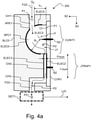
- the counter-electrode ELEC0 may be substantially hemispherical.
- the counter-electrode ELEC0 may have a surface portion, which is substantially hemispherical.
- the counter-electrode ELEC0 may have a substantially spherical surface to define a hollow half of a sphere.
- the corona electrode ELEC3 may be a conductive element which has an exposed sharp tip.
- the tip of the corona electrode ELEC3 may be located at an axis of symmetry of the hemispherical charging space SPC1.
- the distance between the tip and each point of the hemispherical portion of the electrode ELEC0 may be substantially equal to R 1 .
- the charging of the particles may take place in the charging space SPC1 between the corona electrode ELEC3 and the counter-electrode ELEC0.
- the corona electrode ELEC3 may have a substantially sharp tip.
- the radius of curvature of the tip may be e.g. smaller than 0.2 mm.
- the distance between the tip of the corona electrode ELEC3 and the counter-electrode ELEC0 may be substantially equal to R 1 .
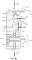
- the monitoring unit 200 may comprise the ion trap JTRAP1 to remove ions J1 from the flow FG2.
- the gas flow FG2, the charged particles P2, and the ions J1 may be guided from the charging space SPC1 into the ion trap JTRAP1.
- the ion trap JTRAP1 may be located between the charging space SPC1 and the detector DET1.
- the gas flow FG2 and the charged particles P2 may be guided from the ion trap JTRAP1 to the detector DET1.
- the ion trap JTRAP1 may be positioned downstream of the charging unit CUNIT1 and upstream of the detector DET1.
- the ion trap JTRAP1 may remove at least a part of the ions J1 from the flow FG2, which is guided to the detector DET1.
- the particle monitoring device 200 may be electrically connected to a first voltage supply 410, to a second voltage supply 420, and to a current monitoring unit CMU1.
- the first voltage supply 410 may provide a voltage Uc, which may be applied to the corona electrode ELEC3 for generating the corona discharge.
- the first voltage supply 410 may provide a voltage Uc with respect to the electrical ground GND.
- the electrical ground GND may have a voltage U 0 .
- the counter electrode ELEC0 may be connected to the electrical ground GND.
- the body BLC0 may be connected to the electrical ground GND.
- the body BLC0 may be connected to the electrical ground GND e.g. by the connecting element PIN1.
- the device 200 may optionally comprise a heating element HUNIT1 for heating the device 200 when the corona discharge DSR1 is not operating.
- the first result m tot,1 and/or the second result m tot,2 may be determined to be invalid e.g. if the following condition is not fulfilled: 0.8 ⁇ m tot , 1 / m tot , 2 SUM1 / SUM2 ⁇ 1.2
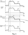
- the monitor signal S1(t) may be compared with the process indicator signal P(t) in order to determine whether a change of an operating parameter of the aerosol particle source SRC1 corresponds to a change of the monitor signal S1(t).
- the monitor signal S1(t) may be compared with the process indicator signal P(t) in order to determine whether a change of an operating parameter of the source SRC1 temporally coincides with a change of the monitor signal S1(t).
- the monitor signal S1(t) may be compared with the process indicator signal P(t) in order to determine whether the monitor signal S1(t) correlates with the process indicator signal P(t).
- the method may comprise calculating a cross-correlation between the electric current signal l p (t) and the first process indicator signal P(t), and checking whether the cross-correlation is higher than a predetermined value.
- Said determining may comprise e.g. checking whether a change of the electric current signal l p (t) temporally coincides with a change of the process indicator signal P(t).
- the result m tot,1 may be determined to be valid e.g. if all significant changes ( ⁇ I p ) of the current signal l p (t) temporally coincide with changes of at least one process indicator signal obtained from the particle source SRC1.
- the result m tot,1 may be determined to be invalid e.g. if all process indicator signals obtained from the particle source SRC1 are substantially constant during the time period which comprises the time t d .
Landscapes
- Chemical & Material Sciences (AREA)
- Physics & Mathematics (AREA)
- General Physics & Mathematics (AREA)
- Engineering & Computer Science (AREA)
- Pathology (AREA)
- Health & Medical Sciences (AREA)
- Life Sciences & Earth Sciences (AREA)
- Analytical Chemistry (AREA)
- Biochemistry (AREA)
- General Health & Medical Sciences (AREA)
- Immunology (AREA)
- Combustion & Propulsion (AREA)
- Dispersion Chemistry (AREA)
- Plasma & Fusion (AREA)
- Chemical Kinetics & Catalysis (AREA)
- Electrochemistry (AREA)
- Other Investigation Or Analysis Of Materials By Electrical Means (AREA)
Claims (13)
- Partikelmesseinrichtung (200, 500), umfassend:- eine Ladeeinheit (CUNIT1) zum Bilden von geladenen Partikeln (P2) aus Aerosolpartikeln (P1), die von einem Eingangsstrom (FG2) transportiert werden; und- einen Partikeldetektor (DET1) zum Bereitstellen eines elektrischen Stroms (Ip(t)) durch Sammeln der geladenen Partikel (P2),wobei die Ladeinheit (CUNIT1) ihrerseits Folgendes umfasst:- eine Gegenelektrode (ELECO),- einen Eintrittskanal (CH1) zum Leiten von Aerosolpartikeln (P1) in einen Laderaum (SPC1),- eine Koronaelektrode (ELEC3) zum Bilden von geladenen Partikeln (P2) aus Aerosolpartikeln (P1), indem eine Koronaentladung (DSR1) erzeugt wird, und- einen Austrittskanal (CH2) zum Leiten der geladenen Partikel (P2) von dem Laderaum (SPC1) zu dem Detektor (DET1),dadurch gekennzeichnet, dass die Gegenelektrode (ELEC0) einen im Wesentlichen halbkugelförmigen Teil aufweist, der den Laderaum (SPC1) definiert, und dass die Koronaelektrode (ELEC3) so angeordnet ist, dass eine Koronaentladung (DSR1) im Laderaum (SPC1) erzeugt wird.
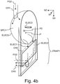
- Einrichtung (200, 500) nach Anspruch 1, die eine elektrisch isolierende Abdeckung (CVR1) umfasst, wobei der Laderaum (SPC1) teilweise durch eine planare Innenfläche der Abdeckung (CVR1) definiert ist.
- Einrichtung (200, 500) nach Anspruch 2, wobei die Koronaelektrode (ELEC3) von der elektrisch isolierenden Abdeckung (CVR1) gelagert wird.
- Einrichtung (200, 500) nach einem der Ansprüche 1 bis 3, wobei die Koronaelektrode (ELEC3) zum Ausbilden der Koronaentladung (DSR1) eine Spitze aufweist.
- Einrichtung (200, 500) nach einem der Ansprüche 1 bis 4, die eine Ionenfalle (JTRAP) umfasst, um Ionen (J1) aus dem Austrittskanal (CH2) zu entfernen, wobei die Ionenfalle (JTRAP) eine erste Ablenkelektrode (ELEC1) und eine zweite Ablenkelektrode (ELEC2) umfasst.
- Einrichtung (200, 500) nach Anspruch 5, die eine elektrisch isolierende Abdeckung (CVR1) der Ladeeinheit (CUNIT1) umfasst, wobei der Laderaum (SPC1) teilweise durch eine planare Innenfläche der Abdeckung (CVR1) definiert ist; und wobei die zweite Ablenkelektrode (ELEC2) an der elektrisch isolierenden Abdeckung (CVR1) angebracht ist.
- Einrichtung (200, 500) nach Anspruch 5 oder 6, wobei die Gegenelektrode (ELEC0) mit der ersten Ablenkelektrode (ELEC1) galvanisch verbunden ist.
- Einrichtung (200, 500) nach einem der Ansprüche 1 bis 7, die eine Stromüberwachungseinheit (CMU1) zum Messen des elektrischen Stroms (Ip(t)), der von dem Partikeldetektor (DET1) bereitgestellt wird, umfasst sowie ein Heizelement (HUNIT1) zum Heizen der Stromüberwachungseinheit (CMU1); und wobei die Einrichtung (200, 500) so aufgebaut ist, dass die Heizleistung des Heizelements (HUNIT1) gesteuert wird, um die Betriebstemperatur der Stromüberwachungseinheit (CMU1) zu stabilisieren.
- Einrichtung (500) nach Anspruch 5 oder 6, wobei die Einrichtung (500) Folgendes umfasst:- eine Spannungsversorgung (420) und- eine Näherungsmesseinheit (430), um zu überwachen, ob eine einwandfreie elektrische Verbindung zwischen der zweiten Ablenkelektrode (ELEC2) der Einrichtung (500) und der Spannungsversorgung (420) gebildet wird.
- Verfahren zur Messung von Aerosolpartikeln (P1), wobei das Verfahren Folgendes umfasst:- Leiten der Aerosolpartikel (P1) über einen Eintrittskanal (CH1) in einen Laderaum (SPC1),- Bilden von geladenen Partikeln (P2) aus den Aerosolpartikeln (P1) durch Erzeugen einer Koronaentladung (DSR1),- Leiten der geladenen Partikel (P2) von dem Laderaum (SPC1) zu einem Detektor (DET1) und- Bereitstellen eines elektrischen Stroms (Ip(t)) durch Verwendung des Detektors (DET1) mittels Sammeln der geladenen Partikel (P2),wobei die Koronaentladung (DSR1) durch eine Koronaelektrode (ELEC3) und eine Gegenelektrode (ELECO) erzeugt wird,dadurch gekennzeichnet, dass die Gegenelektrode (ELEC0) einen im Wesentlichen halbkugelförmigen Teil aufweist, der den Laderaum (SPC1) definiert, und dass die Koronaelektrode (ELEC3) so angeordnet ist, dass die Koronaentladung (DSR1) im Laderaum (SPC1) erzeugt wird.
- Verfahren nach Anspruch 10, das den Steuerbetrieb eines Messgeräts (100) auf Basis des elektrischen Stroms (Ip(t)) umfasst, der durch Verwendung des Detektors (DET1) bereitgestellt wird.
- Verfahren nach Anspruch 10 oder 11, umfassend:- Erhalten eines Messergebnisses durch Verwendung eines Messgeräts (100) und- Bestimmen der Gültigkeit des Messergebnisses durch Analyse des elektrischen Stroms (IP(t)), der durch die Verwendung des Detektors (DET1) bereitgestellt wird.
- Verfahren nach einem der Ansprüche 10 bis 12, wobei das Bereitstellen des Eingangsstroms (FG0) durch Probenahme von Rauchgas (PG0) einer Verbrennungsanlage (SRC1), durch Probenahme von Abgas (PG0) eines Motors oder durch Probenahme aus einem Umgebungsgas (PG0) umfasst.
Applications Claiming Priority (2)
| Application Number | Priority Date | Filing Date | Title |
|---|---|---|---|
| FI20155760A FI20155760A (fi) | 2015-10-26 | 2015-10-26 | Varaajayksikkö hiukkasmonitorointilaitteistoa varten sekä hiukkasmonitorointilaitteisto |
| PCT/FI2016/050684 WO2017072395A1 (en) | 2015-10-26 | 2016-10-03 | A charging unit for a particle monitoring apparatus, and a particle monitoring apparatus |
Publications (3)
| Publication Number | Publication Date |
|---|---|
| EP3368889A1 EP3368889A1 (de) | 2018-09-05 |
| EP3368889A4 EP3368889A4 (de) | 2019-07-10 |
| EP3368889B1 true EP3368889B1 (de) | 2022-02-02 |
Family
ID=58629815
Family Applications (1)
| Application Number | Title | Priority Date | Filing Date |
|---|---|---|---|
| EP16859133.7A Active EP3368889B1 (de) | 2015-10-26 | 2016-10-03 | Ladeeinheit für teilchenüberwachungsvorrichtung und teilchenüberwachungsvorrichtung |
Country Status (6)
| Country | Link |
|---|---|
| US (1) | US11101622B2 (de) |
| EP (1) | EP3368889B1 (de) |
| JP (1) | JP6755049B2 (de) |
| CN (1) | CN108369210B (de) |
| FI (1) | FI20155760A (de) |
| WO (1) | WO2017072395A1 (de) |
Families Citing this family (6)
| Publication number | Priority date | Publication date | Assignee | Title |
|---|---|---|---|---|
| SE542019C2 (en) | 2018-06-08 | 2020-02-11 | Fumex Ab | Support arm arrangement for a local gas extractor, and a local gas extractor with such a support arm arrangement |
| EP4010986A4 (de) * | 2019-08-09 | 2023-09-20 | Particle Measuring Systems, Inc. | Benutzerzugangseinschränkende systeme und verfahren zum betreiben von teilchenabtastungsvorrichtungen |
| FI129009B (en) * | 2020-02-05 | 2021-05-14 | Dekati Oy | Method and device for monitoring the density of aerosol particles |
| RU2743089C1 (ru) * | 2020-09-09 | 2021-02-15 | Акционерное общество "Лётно-исследовательский институт имени М.М. Громова" | Способ определения величины тока выноса электрически заряженных частиц в выхлопной струе авиационного газотурбинного двигателя в полёте |
| EP4424412A1 (de) * | 2023-03-01 | 2024-09-04 | Catalytic Instruments GmbH & Co. KG | Vorrichtung, anordnung und verfahren zur herstellung eines aerosols aus geladenen nanopartikeln |
| TWI902274B (zh) * | 2024-05-30 | 2025-10-21 | 桓達科技股份有限公司 | 針對懸浮粒子濃度的資料處理裝置以及方法 |
Citations (1)
| Publication number | Priority date | Publication date | Assignee | Title |
|---|---|---|---|---|
| EP1924836B1 (de) * | 2005-06-28 | 2017-11-29 | Koninklijke Philips N.V. | Sensor für ultrafeine teilchen |
Family Cites Families (33)
| Publication number | Priority date | Publication date | Assignee | Title |
|---|---|---|---|---|
| US3114877A (en) | 1956-10-30 | 1963-12-17 | Gen Electric | Particle detector having improved unipolar charging structure |
| US3742475A (en) | 1971-03-16 | 1973-06-26 | Tif Instr Inc | Gaseous impurity detector employing corona discharge phenomenon |
| US3949390A (en) | 1974-06-05 | 1976-04-06 | Rca Corporation | High voltage aerosol detector |
| CN85106165B (zh) * | 1985-08-15 | 1988-06-15 | 株式会社日立制作所 | 探测空-燃比的装置和方法 |
| DE4008348A1 (de) | 1990-03-15 | 1991-09-19 | Norbert B Dipl Ing Bernigau | Einrichtung zur messung von aerosolparametern |
| US6228149B1 (en) * | 1999-01-20 | 2001-05-08 | Patterson Technique, Inc. | Method and apparatus for moving, filtering and ionizing air |
| US6502450B1 (en) | 1999-05-10 | 2003-01-07 | Rupprecht & Patashnik Company, Inc. | Single detector differential particulate mass monitor with intrinsic correction for volatilization losses |
| CN2608984Y (zh) * | 2003-05-15 | 2004-03-31 | 中国科学院金属研究所 | 一种纳米炭材料场致发射性能测试装置 |
| FI118278B (fi) * | 2003-06-24 | 2007-09-14 | Dekati Oy | Menetelmä ja anturilaite hiukkaspäästöjen mittaamiseksi polttomoottorin pakokaasuista |
| JP4486799B2 (ja) * | 2003-09-12 | 2010-06-23 | 株式会社堀場製作所 | 粒子状物質測定方法および装置 |
| US7174767B2 (en) * | 2003-12-01 | 2007-02-13 | Sensors, Inc. | Particulate matter analyzer and method of analysis |
| JP4652786B2 (ja) | 2004-11-30 | 2011-03-16 | 株式会社堀場製作所 | 排気ガス分析装置及び混合システム |
| EP1681550A1 (de) * | 2005-01-13 | 2006-07-19 | Matter Engineering AG | Verfahren und Vorrichtung zur Messung von Anzahlkonzentration und mittlerem Durchmesser von Aerosolpartikeln |
| WO2006127803A2 (en) | 2005-05-23 | 2006-11-30 | Tsi Incorporated | Instruments for measuring nanoparticle exposure |
| WO2007072942A1 (ja) | 2005-12-22 | 2007-06-28 | Shimadzu Corporation | 分級装置及び微粒子測定装置 |
| US8044350B2 (en) | 2007-11-29 | 2011-10-25 | Washington University | Miniaturized ultrafine particle sizer and monitor |
| FI20080182A0 (fi) * | 2008-03-04 | 2008-03-04 | Navaro 245 Oy | Mittausmenetelmä ja -laite |
| JP5269794B2 (ja) | 2008-07-16 | 2013-08-21 | 株式会社堀場製作所 | 粒子状物質測定装置 |
| AU2010248679B2 (en) * | 2009-05-12 | 2013-08-15 | Daikin Industries, Ltd. | Liquid treatment discharge unit, humidity control device, and water heater |
| JP2011069268A (ja) * | 2009-09-25 | 2011-04-07 | Ngk Insulators Ltd | 排気ガス処理装置 |
| FI122485B (fi) * | 2009-10-01 | 2012-02-15 | Jorma Keskinen | Menetelmä ja laitteisto kaasun puhdistamiseksi |
| JP5652851B2 (ja) | 2010-02-02 | 2015-01-14 | 独立行政法人理化学研究所 | 微分型電気移動度分級装置、粒子計測システム、及び粒子選別システム |
| US8859957B2 (en) * | 2010-02-26 | 2014-10-14 | Purdue Research Foundation | Systems and methods for sample analysis |
| US9764333B2 (en) | 2010-03-10 | 2017-09-19 | Msp Corporation | Electrical ionizer for aerosol charge conditioning and measurement |
| FIU20100360U0 (fi) | 2010-08-20 | 2010-08-20 | Kauko Janka | Sähköinen hiukkasmittauslaite |
| CN102147350B (zh) | 2011-03-17 | 2012-07-11 | 何宗彦 | 气溶胶粒子浓度和尺寸分布的快速检测方法及其装置 |
| US8779717B2 (en) * | 2011-12-02 | 2014-07-15 | Lear Corporation | Offline power supply and charging apparatus |
| EP2815473A1 (de) | 2012-02-18 | 2014-12-24 | Pegasor OY | Vorrichtung und verfahren zur herstellung eines bestätigten luftstroms und verwendung einer solchen vorrichtung zur messung einer partikelkonzentration in einem bestätigten luftstrom |
| WO2013132154A1 (en) | 2012-03-05 | 2013-09-12 | Pegasor Oy | Apparatus and process for particle mass concentration measurement and use of an apparatus for particle mass concentration measurement |
| JP6138652B2 (ja) | 2013-10-01 | 2017-05-31 | 日本特殊陶業株式会社 | 微粒子測定システム |
| CN103926178A (zh) | 2014-04-30 | 2014-07-16 | 天津圣纳科技有限公司 | 对可吸入颗粒物分类并测量浓度的机构及其检测方法 |
| US9791361B2 (en) | 2015-10-26 | 2017-10-17 | Dekati Oy | Method and apparatus for measuring aerosol particles of exhaust gas |
| US9791360B2 (en) | 2015-10-26 | 2017-10-17 | Dekati Oy | Method and apparatus for measuring aerosol particles suspended in gas |
-
2015
- 2015-10-26 FI FI20155760A patent/FI20155760A/fi not_active Application Discontinuation
-
2016
- 2016-10-03 JP JP2018540221A patent/JP6755049B2/ja active Active
- 2016-10-03 CN CN201680076320.2A patent/CN108369210B/zh active Active
- 2016-10-03 WO PCT/FI2016/050684 patent/WO2017072395A1/en not_active Ceased
- 2016-10-03 US US15/771,142 patent/US11101622B2/en active Active
- 2016-10-03 EP EP16859133.7A patent/EP3368889B1/de active Active
Patent Citations (1)
| Publication number | Priority date | Publication date | Assignee | Title |
|---|---|---|---|---|
| EP1924836B1 (de) * | 2005-06-28 | 2017-11-29 | Koninklijke Philips N.V. | Sensor für ultrafeine teilchen |
Also Published As
| Publication number | Publication date |
|---|---|
| US20180331510A1 (en) | 2018-11-15 |
| EP3368889A1 (de) | 2018-09-05 |
| JP2018533020A (ja) | 2018-11-08 |
| FI20155760A7 (fi) | 2017-04-27 |
| CN108369210B (zh) | 2019-12-06 |
| CN108369210A (zh) | 2018-08-03 |
| US11101622B2 (en) | 2021-08-24 |
| EP3368889A4 (de) | 2019-07-10 |
| FI20155760A (fi) | 2017-04-27 |
| JP6755049B2 (ja) | 2020-09-16 |
| WO2017072395A1 (en) | 2017-05-04 |
Similar Documents
| Publication | Publication Date | Title |
|---|---|---|
| EP3368881B1 (de) | Verfahren und vorrichtung zur messung von in einem gas suspendierten aerosolpartikeln | |
| EP3368882B1 (de) | Verfahren und vorrichtung zur messung von aerosolpartikeln aus abgas | |
| EP3368889B1 (de) | Ladeeinheit für teilchenüberwachungsvorrichtung und teilchenüberwachungsvorrichtung | |
| EP2853882B1 (de) | Messvorrichtung für partikelzählung | |
| EP2370802B1 (de) | Sensor zur wahrnehmung in der luft befindlicher partikel | |
| KR102844148B1 (ko) | 에어로졸 입자들의 개수 밀도를 모니터링하기 위한 방법 및 장치 | |
| EP2223080B1 (de) | Vorrichtung zur kennzeichnung der grössenverteilung elektrisch geladener luftpartikel in einem luftstrom | |
| KR101540913B1 (ko) | 공기 흐름 내의 전기적으로 충전된 공기 중 입자들의 크기 분포를 특징화하기 위한 장치 | |
| Rostedt et al. | Non-collecting electrical sensor for particle concentration measurement | |
| Gong | Novel electrostatic particle sizer (NEPS) using a unipolar charger and 5-stage non-bouncing impactors with Faraday cage-electrometers (20 nm to 560 nm) |
Legal Events
| Date | Code | Title | Description |
|---|---|---|---|
| STAA | Information on the status of an ep patent application or granted ep patent |
Free format text: STATUS: THE INTERNATIONAL PUBLICATION HAS BEEN MADE |
|
| PUAI | Public reference made under article 153(3) epc to a published international application that has entered the european phase |
Free format text: ORIGINAL CODE: 0009012 |
|
| STAA | Information on the status of an ep patent application or granted ep patent |
Free format text: STATUS: REQUEST FOR EXAMINATION WAS MADE |
|
| 17P | Request for examination filed |
Effective date: 20180517 |
|
| AK | Designated contracting states |
Kind code of ref document: A1 Designated state(s): AL AT BE BG CH CY CZ DE DK EE ES FI FR GB GR HR HU IE IS IT LI LT LU LV MC MK MT NL NO PL PT RO RS SE SI SK SM TR |
|
| AX | Request for extension of the european patent |
Extension state: BA ME |
|
| DAV | Request for validation of the european patent (deleted) | ||
| DAX | Request for extension of the european patent (deleted) | ||
| A4 | Supplementary search report drawn up and despatched |
Effective date: 20190607 |
|
| RIC1 | Information provided on ipc code assigned before grant |
Ipc: G01N 27/70 20060101AFI20190603BHEP Ipc: G01M 15/10 20060101ALI20190603BHEP Ipc: G01N 15/06 20060101ALI20190603BHEP Ipc: H01T 19/04 20060101ALI20190603BHEP Ipc: G01N 15/00 20060101ALN20190603BHEP |
|
| RIC1 | Information provided on ipc code assigned before grant |
Ipc: G01N 15/00 20060101ALN20210716BHEP Ipc: H01T 19/04 20060101ALI20210716BHEP Ipc: G01M 15/10 20060101ALI20210716BHEP Ipc: G01N 15/06 20060101ALI20210716BHEP Ipc: G01N 27/70 20060101AFI20210716BHEP |
|
| RIC1 | Information provided on ipc code assigned before grant |
Ipc: G01N 15/00 20060101ALN20210813BHEP Ipc: H01T 19/04 20060101ALI20210813BHEP Ipc: G01M 15/10 20060101ALI20210813BHEP Ipc: G01N 15/06 20060101ALI20210813BHEP Ipc: G01N 27/70 20060101AFI20210813BHEP |
|
| GRAP | Despatch of communication of intention to grant a patent |
Free format text: ORIGINAL CODE: EPIDOSNIGR1 |
|
| STAA | Information on the status of an ep patent application or granted ep patent |
Free format text: STATUS: GRANT OF PATENT IS INTENDED |
|
| INTG | Intention to grant announced |
Effective date: 20210924 |
|
| GRAS | Grant fee paid |
Free format text: ORIGINAL CODE: EPIDOSNIGR3 |
|
| GRAA | (expected) grant |
Free format text: ORIGINAL CODE: 0009210 |
|
| STAA | Information on the status of an ep patent application or granted ep patent |
Free format text: STATUS: THE PATENT HAS BEEN GRANTED |
|
| AK | Designated contracting states |
Kind code of ref document: B1 Designated state(s): AL AT BE BG CH CY CZ DE DK EE ES FI FR GB GR HR HU IE IS IT LI LT LU LV MC MK MT NL NO PL PT RO RS SE SI SK SM TR |
|
| REG | Reference to a national code |
Ref country code: GB Ref legal event code: FG4D |
|
| REG | Reference to a national code |
Ref country code: CH Ref legal event code: EP Ref country code: AT Ref legal event code: REF Ref document number: 1466712 Country of ref document: AT Kind code of ref document: T Effective date: 20220215 |
|
| REG | Reference to a national code |
Ref country code: DE Ref legal event code: R096 Ref document number: 602016068853 Country of ref document: DE |
|
| REG | Reference to a national code |
Ref country code: IE Ref legal event code: FG4D |
|
| REG | Reference to a national code |
Ref country code: LT Ref legal event code: MG9D |
|
| REG | Reference to a national code |
Ref country code: NL Ref legal event code: MP Effective date: 20220202 |
|
| PG25 | Lapsed in a contracting state [announced via postgrant information from national office to epo] |
Ref country code: SE Free format text: LAPSE BECAUSE OF FAILURE TO SUBMIT A TRANSLATION OF THE DESCRIPTION OR TO PAY THE FEE WITHIN THE PRESCRIBED TIME-LIMIT Effective date: 20220202 Ref country code: RS Free format text: LAPSE BECAUSE OF FAILURE TO SUBMIT A TRANSLATION OF THE DESCRIPTION OR TO PAY THE FEE WITHIN THE PRESCRIBED TIME-LIMIT Effective date: 20220202 Ref country code: PT Free format text: LAPSE BECAUSE OF FAILURE TO SUBMIT A TRANSLATION OF THE DESCRIPTION OR TO PAY THE FEE WITHIN THE PRESCRIBED TIME-LIMIT Effective date: 20220602 Ref country code: NO Free format text: LAPSE BECAUSE OF FAILURE TO SUBMIT A TRANSLATION OF THE DESCRIPTION OR TO PAY THE FEE WITHIN THE PRESCRIBED TIME-LIMIT Effective date: 20220502 Ref country code: NL Free format text: LAPSE BECAUSE OF FAILURE TO SUBMIT A TRANSLATION OF THE DESCRIPTION OR TO PAY THE FEE WITHIN THE PRESCRIBED TIME-LIMIT Effective date: 20220202 Ref country code: LT Free format text: LAPSE BECAUSE OF FAILURE TO SUBMIT A TRANSLATION OF THE DESCRIPTION OR TO PAY THE FEE WITHIN THE PRESCRIBED TIME-LIMIT Effective date: 20220202 Ref country code: HR Free format text: LAPSE BECAUSE OF FAILURE TO SUBMIT A TRANSLATION OF THE DESCRIPTION OR TO PAY THE FEE WITHIN THE PRESCRIBED TIME-LIMIT Effective date: 20220202 Ref country code: ES Free format text: LAPSE BECAUSE OF FAILURE TO SUBMIT A TRANSLATION OF THE DESCRIPTION OR TO PAY THE FEE WITHIN THE PRESCRIBED TIME-LIMIT Effective date: 20220202 Ref country code: BG Free format text: LAPSE BECAUSE OF FAILURE TO SUBMIT A TRANSLATION OF THE DESCRIPTION OR TO PAY THE FEE WITHIN THE PRESCRIBED TIME-LIMIT Effective date: 20220502 |
|
| PG25 | Lapsed in a contracting state [announced via postgrant information from national office to epo] |
Ref country code: PL Free format text: LAPSE BECAUSE OF FAILURE TO SUBMIT A TRANSLATION OF THE DESCRIPTION OR TO PAY THE FEE WITHIN THE PRESCRIBED TIME-LIMIT Effective date: 20220202 Ref country code: LV Free format text: LAPSE BECAUSE OF FAILURE TO SUBMIT A TRANSLATION OF THE DESCRIPTION OR TO PAY THE FEE WITHIN THE PRESCRIBED TIME-LIMIT Effective date: 20220202 Ref country code: GR Free format text: LAPSE BECAUSE OF FAILURE TO SUBMIT A TRANSLATION OF THE DESCRIPTION OR TO PAY THE FEE WITHIN THE PRESCRIBED TIME-LIMIT Effective date: 20220503 Ref country code: FI Free format text: LAPSE BECAUSE OF FAILURE TO SUBMIT A TRANSLATION OF THE DESCRIPTION OR TO PAY THE FEE WITHIN THE PRESCRIBED TIME-LIMIT Effective date: 20220202 |
|
| PG25 | Lapsed in a contracting state [announced via postgrant information from national office to epo] |
Ref country code: IS Free format text: LAPSE BECAUSE OF FAILURE TO SUBMIT A TRANSLATION OF THE DESCRIPTION OR TO PAY THE FEE WITHIN THE PRESCRIBED TIME-LIMIT Effective date: 20220602 |
|
| PG25 | Lapsed in a contracting state [announced via postgrant information from national office to epo] |
Ref country code: SM Free format text: LAPSE BECAUSE OF FAILURE TO SUBMIT A TRANSLATION OF THE DESCRIPTION OR TO PAY THE FEE WITHIN THE PRESCRIBED TIME-LIMIT Effective date: 20220202 Ref country code: SK Free format text: LAPSE BECAUSE OF FAILURE TO SUBMIT A TRANSLATION OF THE DESCRIPTION OR TO PAY THE FEE WITHIN THE PRESCRIBED TIME-LIMIT Effective date: 20220202 Ref country code: RO Free format text: LAPSE BECAUSE OF FAILURE TO SUBMIT A TRANSLATION OF THE DESCRIPTION OR TO PAY THE FEE WITHIN THE PRESCRIBED TIME-LIMIT Effective date: 20220202 Ref country code: EE Free format text: LAPSE BECAUSE OF FAILURE TO SUBMIT A TRANSLATION OF THE DESCRIPTION OR TO PAY THE FEE WITHIN THE PRESCRIBED TIME-LIMIT Effective date: 20220202 Ref country code: DK Free format text: LAPSE BECAUSE OF FAILURE TO SUBMIT A TRANSLATION OF THE DESCRIPTION OR TO PAY THE FEE WITHIN THE PRESCRIBED TIME-LIMIT Effective date: 20220202 Ref country code: CZ Free format text: LAPSE BECAUSE OF FAILURE TO SUBMIT A TRANSLATION OF THE DESCRIPTION OR TO PAY THE FEE WITHIN THE PRESCRIBED TIME-LIMIT Effective date: 20220202 |
|
| REG | Reference to a national code |
Ref country code: DE Ref legal event code: R097 Ref document number: 602016068853 Country of ref document: DE |
|
| PG25 | Lapsed in a contracting state [announced via postgrant information from national office to epo] |
Ref country code: AL Free format text: LAPSE BECAUSE OF FAILURE TO SUBMIT A TRANSLATION OF THE DESCRIPTION OR TO PAY THE FEE WITHIN THE PRESCRIBED TIME-LIMIT Effective date: 20220202 |
|
| PLBE | No opposition filed within time limit |
Free format text: ORIGINAL CODE: 0009261 |
|
| STAA | Information on the status of an ep patent application or granted ep patent |
Free format text: STATUS: NO OPPOSITION FILED WITHIN TIME LIMIT |
|
| 26N | No opposition filed |
Effective date: 20221103 |
|
| PG25 | Lapsed in a contracting state [announced via postgrant information from national office to epo] |
Ref country code: SI Free format text: LAPSE BECAUSE OF FAILURE TO SUBMIT A TRANSLATION OF THE DESCRIPTION OR TO PAY THE FEE WITHIN THE PRESCRIBED TIME-LIMIT Effective date: 20220202 |
|
| REG | Reference to a national code |
Ref country code: AT Ref legal event code: UEP Ref document number: 1466712 Country of ref document: AT Kind code of ref document: T Effective date: 20220202 |
|
| PG25 | Lapsed in a contracting state [announced via postgrant information from national office to epo] |
Ref country code: MC Free format text: LAPSE BECAUSE OF FAILURE TO SUBMIT A TRANSLATION OF THE DESCRIPTION OR TO PAY THE FEE WITHIN THE PRESCRIBED TIME-LIMIT Effective date: 20220202 |
|
| REG | Reference to a national code |
Ref country code: BE Ref legal event code: MM Effective date: 20221031 |
|
| GBPC | Gb: european patent ceased through non-payment of renewal fee |
Effective date: 20221003 |
|
| PG25 | Lapsed in a contracting state [announced via postgrant information from national office to epo] |
Ref country code: LU Free format text: LAPSE BECAUSE OF NON-PAYMENT OF DUE FEES Effective date: 20221003 |
|
| PG25 | Lapsed in a contracting state [announced via postgrant information from national office to epo] |
Ref country code: IT Free format text: LAPSE BECAUSE OF FAILURE TO SUBMIT A TRANSLATION OF THE DESCRIPTION OR TO PAY THE FEE WITHIN THE PRESCRIBED TIME-LIMIT Effective date: 20220202 Ref country code: FR Free format text: LAPSE BECAUSE OF NON-PAYMENT OF DUE FEES Effective date: 20221031 |
|
| PG25 | Lapsed in a contracting state [announced via postgrant information from national office to epo] |
Ref country code: BE Free format text: LAPSE BECAUSE OF NON-PAYMENT OF DUE FEES Effective date: 20221031 |
|
| PG25 | Lapsed in a contracting state [announced via postgrant information from national office to epo] |
Ref country code: IE Free format text: LAPSE BECAUSE OF NON-PAYMENT OF DUE FEES Effective date: 20221003 Ref country code: GB Free format text: LAPSE BECAUSE OF NON-PAYMENT OF DUE FEES Effective date: 20221003 |
|
| PG25 | Lapsed in a contracting state [announced via postgrant information from national office to epo] |
Ref country code: HU Free format text: LAPSE BECAUSE OF FAILURE TO SUBMIT A TRANSLATION OF THE DESCRIPTION OR TO PAY THE FEE WITHIN THE PRESCRIBED TIME-LIMIT; INVALID AB INITIO Effective date: 20161003 |
|
| PG25 | Lapsed in a contracting state [announced via postgrant information from national office to epo] |
Ref country code: CY Free format text: LAPSE BECAUSE OF FAILURE TO SUBMIT A TRANSLATION OF THE DESCRIPTION OR TO PAY THE FEE WITHIN THE PRESCRIBED TIME-LIMIT Effective date: 20220202 |
|
| PG25 | Lapsed in a contracting state [announced via postgrant information from national office to epo] |
Ref country code: MK Free format text: LAPSE BECAUSE OF FAILURE TO SUBMIT A TRANSLATION OF THE DESCRIPTION OR TO PAY THE FEE WITHIN THE PRESCRIBED TIME-LIMIT Effective date: 20220202 |
|
| PG25 | Lapsed in a contracting state [announced via postgrant information from national office to epo] |
Ref country code: MT Free format text: LAPSE BECAUSE OF FAILURE TO SUBMIT A TRANSLATION OF THE DESCRIPTION OR TO PAY THE FEE WITHIN THE PRESCRIBED TIME-LIMIT Effective date: 20220202 |
|
| PGFP | Annual fee paid to national office [announced via postgrant information from national office to epo] |
Ref country code: DE Payment date: 20241018 Year of fee payment: 9 |
|
| PGFP | Annual fee paid to national office [announced via postgrant information from national office to epo] |
Ref country code: CH Payment date: 20241101 Year of fee payment: 9 |
|
| PG25 | Lapsed in a contracting state [announced via postgrant information from national office to epo] |
Ref country code: TR Free format text: LAPSE BECAUSE OF FAILURE TO SUBMIT A TRANSLATION OF THE DESCRIPTION OR TO PAY THE FEE WITHIN THE PRESCRIBED TIME-LIMIT Effective date: 20220202 |
|
| PGFP | Annual fee paid to national office [announced via postgrant information from national office to epo] |
Ref country code: AT Payment date: 20251020 Year of fee payment: 10 |