EP3368837B1 - A device for chilling liquid - Google Patents
A device for chilling liquid Download PDFInfo
- Publication number
- EP3368837B1 EP3368837B1 EP16861038.4A EP16861038A EP3368837B1 EP 3368837 B1 EP3368837 B1 EP 3368837B1 EP 16861038 A EP16861038 A EP 16861038A EP 3368837 B1 EP3368837 B1 EP 3368837B1
- Authority
- EP
- European Patent Office
- Prior art keywords
- tank
- area
- water
- chips
- thermoelectric
- Prior art date
- Legal status (The legal status is an assumption and is not a legal conclusion. Google has not performed a legal analysis and makes no representation as to the accuracy of the status listed.)
- Active
Links
- 239000007788 liquid Substances 0.000 title claims description 21
- XLYOFNOQVPJJNP-UHFFFAOYSA-N water Substances O XLYOFNOQVPJJNP-UHFFFAOYSA-N 0.000 claims description 112
- 238000001816 cooling Methods 0.000 claims description 97
- 238000009413 insulation Methods 0.000 claims description 18
- 125000006850 spacer group Chemical group 0.000 claims description 15
- 239000012530 fluid Substances 0.000 claims description 13
- 239000000463 material Substances 0.000 claims description 8
- 230000009977 dual effect Effects 0.000 description 13
- 238000000034 method Methods 0.000 description 6
- -1 polyethylene Polymers 0.000 description 4
- XAGFODPZIPBFFR-UHFFFAOYSA-N aluminium Chemical compound [Al] XAGFODPZIPBFFR-UHFFFAOYSA-N 0.000 description 3
- 229910052782 aluminium Inorganic materials 0.000 description 3
- 230000008901 benefit Effects 0.000 description 3
- 239000004698 Polyethylene Substances 0.000 description 2
- 239000004743 Polypropylene Substances 0.000 description 2
- 238000009529 body temperature measurement Methods 0.000 description 2
- 230000000694 effects Effects 0.000 description 2
- 238000012986 modification Methods 0.000 description 2
- 230000004048 modification Effects 0.000 description 2
- 238000013021 overheating Methods 0.000 description 2
- 229920000573 polyethylene Polymers 0.000 description 2
- 229920001155 polypropylene Polymers 0.000 description 2
- 238000012546 transfer Methods 0.000 description 2
- 239000004593 Epoxy Substances 0.000 description 1
- 230000005679 Peltier effect Effects 0.000 description 1
- 150000001875 compounds Chemical class 0.000 description 1
- 230000006835 compression Effects 0.000 description 1
- 238000007906 compression Methods 0.000 description 1
- 239000000498 cooling water Substances 0.000 description 1
- 230000035622 drinking Effects 0.000 description 1
- 230000007613 environmental effect Effects 0.000 description 1
- 230000004907 flux Effects 0.000 description 1
- 239000007769 metal material Substances 0.000 description 1
- 230000007935 neutral effect Effects 0.000 description 1
- 230000000737 periodic effect Effects 0.000 description 1
- 229920003002 synthetic resin Polymers 0.000 description 1
- 239000000057 synthetic resin Substances 0.000 description 1
- 238000010792 warming Methods 0.000 description 1
Images


Classifications
-
- F—MECHANICAL ENGINEERING; LIGHTING; HEATING; WEAPONS; BLASTING
- F25—REFRIGERATION OR COOLING; COMBINED HEATING AND REFRIGERATION SYSTEMS; HEAT PUMP SYSTEMS; MANUFACTURE OR STORAGE OF ICE; LIQUEFACTION SOLIDIFICATION OF GASES
- F25B—REFRIGERATION MACHINES, PLANTS OR SYSTEMS; COMBINED HEATING AND REFRIGERATION SYSTEMS; HEAT PUMP SYSTEMS
- F25B21/00—Machines, plants or systems, using electric or magnetic effects
- F25B21/02—Machines, plants or systems, using electric or magnetic effects using Peltier effect; using Nernst-Ettinghausen effect
-
- B—PERFORMING OPERATIONS; TRANSPORTING
- B67—OPENING, CLOSING OR CLEANING BOTTLES, JARS OR SIMILAR CONTAINERS; LIQUID HANDLING
- B67D—DISPENSING, DELIVERING OR TRANSFERRING LIQUIDS, NOT OTHERWISE PROVIDED FOR
- B67D1/00—Apparatus or devices for dispensing beverages on draught
- B67D1/08—Details
- B67D1/0857—Cooling arrangements
- B67D1/0869—Cooling arrangements using solid state elements, e.g. Peltier cells
-
- B—PERFORMING OPERATIONS; TRANSPORTING
- B67—OPENING, CLOSING OR CLEANING BOTTLES, JARS OR SIMILAR CONTAINERS; LIQUID HANDLING
- B67D—DISPENSING, DELIVERING OR TRANSFERRING LIQUIDS, NOT OTHERWISE PROVIDED FOR
- B67D3/00—Apparatus or devices for controlling flow of liquids under gravity from storage containers for dispensing purposes
- B67D3/0009—Apparatus or devices for controlling flow of liquids under gravity from storage containers for dispensing purposes provided with cooling arrangements
-
- F—MECHANICAL ENGINEERING; LIGHTING; HEATING; WEAPONS; BLASTING
- F25—REFRIGERATION OR COOLING; COMBINED HEATING AND REFRIGERATION SYSTEMS; HEAT PUMP SYSTEMS; MANUFACTURE OR STORAGE OF ICE; LIQUEFACTION SOLIDIFICATION OF GASES
- F25B—REFRIGERATION MACHINES, PLANTS OR SYSTEMS; COMBINED HEATING AND REFRIGERATION SYSTEMS; HEAT PUMP SYSTEMS
- F25B49/00—Arrangement or mounting of control or safety devices
-
- F—MECHANICAL ENGINEERING; LIGHTING; HEATING; WEAPONS; BLASTING
- F25—REFRIGERATION OR COOLING; COMBINED HEATING AND REFRIGERATION SYSTEMS; HEAT PUMP SYSTEMS; MANUFACTURE OR STORAGE OF ICE; LIQUEFACTION SOLIDIFICATION OF GASES
- F25D—REFRIGERATORS; COLD ROOMS; ICE-BOXES; COOLING OR FREEZING APPARATUS NOT OTHERWISE PROVIDED FOR
- F25D31/00—Other cooling or freezing apparatus
- F25D31/002—Liquid coolers, e.g. beverage cooler
-
- H—ELECTRICITY
- H10—SEMICONDUCTOR DEVICES; ELECTRIC SOLID-STATE DEVICES NOT OTHERWISE PROVIDED FOR
- H10N—ELECTRIC SOLID-STATE DEVICES NOT OTHERWISE PROVIDED FOR
- H10N10/00—Thermoelectric devices comprising a junction of dissimilar materials, i.e. devices exhibiting Seebeck or Peltier effects
- H10N10/10—Thermoelectric devices comprising a junction of dissimilar materials, i.e. devices exhibiting Seebeck or Peltier effects operating with only the Peltier or Seebeck effects
- H10N10/13—Thermoelectric devices comprising a junction of dissimilar materials, i.e. devices exhibiting Seebeck or Peltier effects operating with only the Peltier or Seebeck effects characterised by the heat-exchanging means at the junction
-
- H—ELECTRICITY
- H10—SEMICONDUCTOR DEVICES; ELECTRIC SOLID-STATE DEVICES NOT OTHERWISE PROVIDED FOR
- H10N—ELECTRIC SOLID-STATE DEVICES NOT OTHERWISE PROVIDED FOR
- H10N10/00—Thermoelectric devices comprising a junction of dissimilar materials, i.e. devices exhibiting Seebeck or Peltier effects
- H10N10/10—Thermoelectric devices comprising a junction of dissimilar materials, i.e. devices exhibiting Seebeck or Peltier effects operating with only the Peltier or Seebeck effects
- H10N10/17—Thermoelectric devices comprising a junction of dissimilar materials, i.e. devices exhibiting Seebeck or Peltier effects operating with only the Peltier or Seebeck effects characterised by the structure or configuration of the cell or thermocouple forming the device
-
- F—MECHANICAL ENGINEERING; LIGHTING; HEATING; WEAPONS; BLASTING
- F25—REFRIGERATION OR COOLING; COMBINED HEATING AND REFRIGERATION SYSTEMS; HEAT PUMP SYSTEMS; MANUFACTURE OR STORAGE OF ICE; LIQUEFACTION SOLIDIFICATION OF GASES
- F25B—REFRIGERATION MACHINES, PLANTS OR SYSTEMS; COMBINED HEATING AND REFRIGERATION SYSTEMS; HEAT PUMP SYSTEMS
- F25B2321/00—Details of machines, plants or systems, using electric or magnetic effects
- F25B2321/02—Details of machines, plants or systems, using electric or magnetic effects using Peltier effects; using Nernst-Ettinghausen effects
- F25B2321/023—Mounting details thereof
Definitions
- Exemplary embodiments relate to devices and methods for cooling liquids, such as water for example, using a tank comprising a unique combination of cooling fins and a baffle that work in conjunction with a first and a second thermoelectric chip.
- a preferred exemplary embodiment comprises a cooling tank that receives and selectively maintains a volume of water from a water inlet and that provides chilled water to a water outlet, a baffle having a first side and a second side and that is disposed within the tank such that water within the tank is received from the inlet into a first area of the tank that is largely defined by the first side of the baffle and water is removed from the tank by the water outlet from a second area of the tank that is largely defined by the second side of the baffle, a plurality of cooling fins that extend from the first side of the baffle to the second side of the baffle, and dual thermoelectric chips in connectivity with the cooling fins such that heat may be drawn from the fins by the thermoelectric chips causing the volume of water within the tank - on both sides of
- thermoelectric cooling uses the Peltier effect to create a heat flux between the junction of two different types of materials.
- a thermoelectric cooler is a solid-state active heat pump which transfers heat from one side of the device to the other with consumption of electrical energy, depending on the direction of the current.
- Thermoelectric water coolers are well known and have been on the market for more than 20 years. The advantages to thermoelectric water coolers are durability, their lightweight, and compact size as compared to more traditional compressor-driven cooling systems. For example, there are provided cold water tanks having a tank main body divided into a first body and a second body, and a water treatment apparatus cooling a power supply device provided to cool the cold water tank without using an air blower.
- the cold water tank includes: a tank main body including a first body and a second body combined to form an internal space therein; and a cooling unit including a thermoelectric module cooling water accommodated within the tank main body, wherein the first body is made of a synthetic resin material, and the second main body is made of a metallic material.
- thermoelectric water coolers are that they are not as energy efficient as compression-driven cooling systems and they are relatively slow in chilling water.
- EPA Environmental Protection Agency
- WO 2012/091499 A2 discloses a device for chilling liquid, the device comprising: a tank for receiving and selectively maintaining a volume of liquid within its interior; an inlet for receiving the volume of liquid into the tank; an outlet which permits for the liquid to be removed from the tank; a baffle disposed within the tank such that a first side of the baffle assists in defining a first area within the tank interior for receiving water from the inlet and a second side of the baffle assists in defining a second area within the tank interior for holding at least some of the liquid before it is removed from the tank through the outlet; at least one opening defined by at least part of the baffle and part of the interior of the tank body wherein said opening extends between the first area and the second area and permits for liquid to travel from the first area to the second area; a plurality of cooling members; at least one thermoelectric chip in thermal connectivity with the cooling members.
- a device according to claim 1 for chilling liquid is provided.
- the devices according to claims 1-11 provide an energy efficient thermoelectric cooler that solves the problems inherent in the known thermoelectric cooling systems.
- a cooling tank is connected to a water inlet and a water outlet.
- a baffle is disposed within the tank such that it creates a first area for receiving water from the inlet and a second area for providing chilled water to the outlet.
- the baffle does not completely divide the tank but instead permits for water to flow from the first area to the second area within the tank preferably at an opening (or more than one opening in some embodiments) which exists at and is defined by the top of the interior of the tank and the top of the baffle.
- a plurality of cooling fins are also disposed within the tank such that they extend through the baffle and are at least partially exposed to water in both the first area and the second area.
- the plurality of cooling fins are in connectivity with a plurality of thermoelectric chips, but preferably dual thermoelectric chips, that effectuate the cooling of the fins and positioned such that a heat load associated with the chips is spread over a width that is perpendicular to the flow of the liquid within the tank.
- the thermoelectric chips are ideally positioned outside of the tank.
- the cooling fins are positioned at an upper part of the baffle near the opening(s) where water may flow from the first area to the second area.
- the water flows into the first area and cooling of the water may commence due to exposure of at least some of the water in the first area to the cooling fins.
- water may flow from the first area to the second area through the opening(s).
- the cooling fins are disposed at an upper portion of the baffle/tank near the opening(s)
- the cooling fins are actually received by the openings which permit for water to travel from the first area to the second area.
- Such an embodiment permits for flowing water to be chilled as it travels between the first and second areas of the tank.
- thermoelectric chips that provide the cooling to the cooling fins preferably each have a first and second side.
- the first side is cool and is the side which is in connectivity (either direct or indirect) with the cooling fins.
- the second side of the thermoelectric chips is hot and is ideally in connectivity with a heat sink.
- a fan is preferably positioned next to the heat sink such that it can draw air through and cool the heat sink, preventing the heat sink from overheating.
- a benefit of exemplary embodiments of the present invention is that most of the chilled water within the tank can be removed from the tank (via the outlet) with less warming effect of incoming water (from the inlet) resulting in more chilled water volume within the tank that is available for drinking.
- This exemplary thermoelectric cooling system may additionally comprise a first and a second power supply.
- the first power supply preferably provides a high energy output to the fan and thermoelectric chip(s) when more cooling is needed such as for example when there is a need to cool incoming water that has been received from the inlet such that the water within the tank is chilled to a desired set point.
- the second power supply preferably provides a low power output to the fan and thermoelectric chips and can be utilized when less cooling is needed such as, for example, when water that has been in the tank for some time needs periodic cooling to maintain the water at the desired chilled set point. Utilization of dual power supplies increases the efficiency of the exemplary thermoelectric cooling device and assists the device in meeting energy star guidelines.
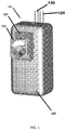
- FIGURE 1 A preferred exemplary embodiment of a cooling device 100 is shown in FIGURE 1 .
- the exemplary system 100 preferably comprises a tank 110 that is connected to a water inlet 120 and a water outlet 130.
- the tank 110 may be fabricated from polyethylene or polypropylene in some exemplary embodiments. As can be seen in FIGURE 2 , the tank 110 may be formed using more than one piece.
- the inlet 120 and outlet 130 are tube-like structures which permit for the travel of liquid to and from the tank 110.
- the inlet 120 and outlet 130 consist of and/or comprise openings defined at least in part by the tank 110 and which permit for liquid to flow into and out of the tank.
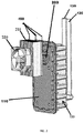
- FIGURE 2 illustrates the exemplary cooling device of FIGURE 1 shown without the insulation layer 300 so that the tank 110 can more clearly be seen.
- a baffle 140 is disposed within the tank 110 such that the baffle 140 defines (preferably in conjunction with the interior of the tank 110 or some other surface) a first area 150 for receiving water from the inlet 120 and a second area 160 for providing chilled water to the outlet 130.
- the baffle 140 does not completely divide the tank 110 such that the first area 150 and the second area 160 are completely separated but instead, the baffle 140 permits for water to flow from the first area 150 to the second area 160 within the tank 110 preferably via at least one opening 170 which exists at and may be defined by the top of the interior of the tank 110 and the top of the baffle 140.
- the baffle 140 may be fabricated from polyethylene or polypropylene in some exemplary embodiments.
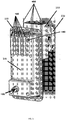
- cooling fins 180 are also disposed within the tank 110 such that the fins 180 extend through the baffle 140 and are at least partially exposed to water in both the first area 150 and the second area 160.
- the cooling fins 180 may be made from anodized aluminum in some exemplary embodiments. Note that in FIGURE 5 , part of the exterior of tank 110 has not been shown in order to more clearly show the configuration of the baffle 140 in relationship with the cooling fins 180.
- Each one of the cooling fins 180 has a surface area which can be exposed to water in the tank 110.
- At least one opening 170 exists about and is defined by at least one of the cold fins 180 and the baffle 140 such that in traveling from area 150 to area 160 the water is exposed to a substantial surface area of the cooling fins 180.
- the plurality of cooling fins 180 is held within their desired location within the tank 110 by attachment to the interior wall of the tank 110.
- the cooling fins 180 may be part of and/or connected to the wall of the tank 110 via a relatively flat plate 181 that extends through the wall of the tank 110.
- the plate 181 and fins 180 are extruded/formed as a single piece.
- the fins 180 are individual pieces of material (such as aluminum) that are received by form-fitting grooves defined by the plate 181 and then the sides of the grooves of the plate 181 are crimped in tightly onto the fins 180 holding them in place.
- the cooling fins 180 may be in thermal connectivity (directly or indirectly) with dual thermoelectric chips 190 that effectuate the cooling of the fins 180 and thus the cooling of water in the tank 110.
- thermoelectric chips 190 are placed in thermal contact/connectivity with the cooling fins 180 by applying a thin layer of heat sink material 401 (for example, a heat sink paste) between the chips 190 and the spacer block 200 and then applying a force to hold the components together.
- heat sink material 401 preferably a compound or thermal paste
- the heat sink material 401 is applied between the heat sink 210 and the thermoelectric chips 190 as well as between the chips 190 and the spacer block 200 as well as between the spacer block 200 and the cooling fins 180 and/or the cooling fin plate 181.
- the force that holds the assembly together may be generated by one or more screws connected to the tank 110.
- thermoelectric chips 190 are placed in thermal contact/connectivity with the cooling fins 180 by bonding the chips 190 to the cooling fins 180 and/or the cooling fin plate 181 using a thermal epoxy. This alone is capable of holding these parts together and providing heat conduction between the chips 190 and the cooling fins 180.
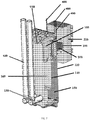
- FIGURE 4 more clearly shows how twin thermoelectric chips 190 may be incorporated into the exemplary device 100.
- the twin thermoelectric chips 190 spread their cooling effect over a wider area within the tank 110 than would be possible via a single chip or two chips disposed in a different configuration. So, rather than having a very cold spot in the center of a single, larger thermoelectric chip, the heat load can be absorbed more evenly and efficiently by the two chips 190. Similarly, heat can be more evenly and efficiently dissipated from the opposite side of the dual, twin chips.
- the twin thermoelectric chips 190 are positioned such that the heat load is spread over a larger width that is perpendicular to the flow of water within the tank 110. Such a configuration is shown in FIGURE 3 .
- thermoelectric chips 190 may be positioned such that the heat load is spread over a larger area that is vertical to the flow of water within the tank 110.
- the heat exchange would decrease. More heat exchange happens when the water and cooling fins 180 are at a greater temperature difference. Also, the water is cold enough when it reached the midpoint. Cooling it further is not necessary.
- such alternate configurations while possible, do not maximize efficiency.
- thermoelectric chips 190 are preferably "twin" (i.e. substantially identical to each other) as has been discussed above. But, some exemplary embodiments may use dual thermoelectric chips 190 where the first and second chips are not substantially identical to each other. For example, a first chip may be larger than the second chip. In some exemplary embodiments, there may be three or more thermoelectric chips (they may be arranged similarly to the description regarding dual chip layouts provided herein) which may further increase the cooling performance. Some exemplary embodiments may comprise a single thermoelectric chip, but these embodiments are not preferred for the aforementioned reasons.
- a spacer block 200 may be positioned between the thermoelectric chips 190 and the tank 110.
- the spacer block 200 conducts heat from the cooling fins 180 to the thermoelectric chips 190.
- the spacer block 200 is made from aluminum. Other materials may be used in other exemplary embodiments. It is preferred that the material utilized for the spacer block 200 is rigid and thermally conductive.
- the spacer block 200 allows for thicker insulation 300 between the heat sink 210 and cooling fins 180 to reduce heat transfer back to the fins 180 from the heat sink 210. The thicker the spacer 200 the thicker the insulation 300. It should be appreciated that there is a balance to be struck between the thickness of the spacer block 200 and the insulation 300 thickness.
- thermoelectric chips 190 are ideally positioned outside of the tank body 110.
- the cooling fins 180 are positioned at an upper part of the baffle 140 near the at least one opening(s) 170 where water may flow from the first area 150 to the second area 160.
- the water flows into the first area 150 and cooling of the water may commence due to exposure of the water in the first area 150 to at least part of the surface area of the cooling fins 180.
- FIGURE 6 uses arrows to illustrate the preferred flow of water from the inlet 120 into space 150 then through the cooling fins 180 and opening(s) 170 to space 160 where the water is selectively maintained until it is removed from the tank 110 via the outlet 130.
- the cooling fins 180 are disposed at an upper portion of the baffle 140 /tank 110 near the opening, the flowing water may be exposed to some of the surface area of the cooling fins 180 in the first area 150 and then also in the second area 160 after the water passes through the opening(s) 170 causing relatively quick chilling of the water.
- the thermoelectric chips 190 that provide the cooling to the cooling fins 180 preferably have a first and second side.
- the first side is cool and is the side which is in connectivity (either direct or indirect) with the cooling fins 180.
- the second side of the thermoelectric chips 190 is hot and is ideally in connectivity with a heat sink 210.
- a fan 220 is preferably positioned next to the heat sink 210 such that it can draw air through and cool the heat sink 210, preventing the heat sink 210 from overheating.
- insulation 300 may surround or substantially surround the tank 110 and may separate the tank 110 from the warm side of the thermoelectric chips 190, the heat sink 210, and the fan 220.
- the insulation 300 may define at least one opening which receives the spacer block 200 so that the thermoelectric chips 190, the heat sink 210, and the fan 220 may be separated from the tank 110 via the insulation 300 which will help keep water held in the tank cool.
- a first power supply is connected to the thermoelectric chips 190 and the fan 220 and is configured to provide a high energy output when more substantial cooling is needed (such as for example, when chilled water has been drawn from the tank 110 and the water volume in the tank 110 is replenished with warmer water received from the inlet 120 ).
- a second power supply is connected to the thermoelectric chips 190 and the fan 220 and is configured to provide a lower energy output when a lesser degree of cooling is needed.
- a single printed circuit board (“PCB”) 500 may comprise a single power supply that is capable of shifting between high power, low power, and no power outputs.
- the PCB 500 will preferably include a power connection comprising a line 501, neutral 502, and ground 503.
- the high power output may be utilized when more significant cooling of the water/fluid in the tank 110 is needed while the lower power output may be utilized when a relatively small amount of cooling of water/fluid in the tank 110 is needed.
- the power supply may be turned off when the ambient temperature of the water/fluid in the tank 110 gets too low and/or when the water in the tank is at a desired temperature and does not need additional cooling.
- a high power output may be approximately 50 Watts (12 Volts Direct Current to the Thermoelectric Chips 190 and Fan 220 ), while a low power output may be an output of approximately 4 Watts (3.1 Volts Direct Current to the Thermoelectric Chip 190 and 6 Volts of Direct Current to the fan 220 ).
- the input power to the PCB 500 is likely greater than the power output by the PCB 500 due to inefficiency.
- the high power input to the PCB 500 when a high power output is being generated would be approximately 75 Watts while the low power input would be 6.2 Watts.
- the input power to the PCB 500 when a low power output is being generated is always less than 6.6 Watts. More details regarding exemplary power supplies that may be used in conjunction with a cooling device 100 are discussed in more detail below.
- the system 100 additionally comprises an electronic control that is in connectivity with at least one temperature sensor 600 that measures (i.e. takes readings of) the water temperature within the tank 110.
- the PCB 500 shown in FIGURE 8 comprises a power supply as well as an electronic control.
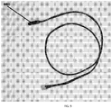
- FIGURE 9 illustrates an exemplary temperature sensor 600 that may be utilized to obtain temperature measurements of the water in the tank. This may be enabled by positioning at least part of the temperature sensor inside of the tank 110.
- FIGURE 10 illustrates the exemplary temperature sensor connected to the exemplary PCB 500.
- some exemplary systems may comprise more than one sensor 600 each of which would be in electronic connectivity directly or indirectly with the electronic control and at least one power supply.
- a sensor 600 may be received by the first area 150 and another sensor 600 may be received by the second area 160.
- the electronic control compares the temperature measurement(s) received from the at least one sensor 600 with a predetermined temperature set point (i.e. the desired temperature of the chilled water in the tank) and sends a corresponding signal to at least one power supply.
- a predetermined temperature set point i.e. the desired temperature of the chilled water in the tank
- the control will shift between the first and second power supplies to provide enough power to the fan 220 and the thermoelectric chips 190 to pull the water temperature down to the cold water set point, maintain the water at the set point, turn off the power to prevent freeze-ups (which tend to occur when the ambient temperature drops to 65 degrees Fahrenheit or lower), etc.
- the second power source may be utilized to send power to the thermoelectric chips 190 and fan 220 when the temperature of the water in the tank 110 is not highly deviated from the set point (for example, when the water in the tank is only 3 or 4 degrees or less off of the set point temperature). But, if the temperature sensor 600 obtains a reading of the water and it is detected that the temperature of the water in the tank 110 is more highly deviated from the temperature set point (for example, if the temperature of the water is 7 or more degrees off of the set point temperature), the control can switch to the first power source such that it is then supplying energy to the chips 190 and fan 220.
- the electronic control is preferably capable of obtaining temperature readings from the temperature sensor 600 and sending signals to the power supply that tell the power supply whether it should provide high power, low power, or no power to the chips 190 and/or fan 220.
- the power source only supplies power to the chips 190 and fan 220 when the water is at least a certain temperature above the set point.
- the set point may be provided to the electronic control and modified by a system user.
- the control may be capable of receiving a set point from a system user and cause the water in the tank 110 to be maintained at the provided set point by instructing the first and/or second power source to send power to the chips 190 and fan 220.
- the control maintains a set point temperature of water in the tank 110 that is not modified by system users.
- Power supplies run most efficiently when they operate at outputs close to the maximum output available. Efficiencies of 75% to 90% are easily achievable. When power supplies operate at low output relative to the maximum output of the power supply, the efficiency can drop to lower than 50%. In the preferred exemplary embodiment of the currently disclosed system 100, the energy required to maintain chilled water within the tank 110 and the set point is less than 4.5 Watts to the fan and the thermoelectric chips. However, when a new volume of warm water is received into the first area 150 of the tank 110 from the inlet 120 and more substantial cooling is needed to pull down the temperature of the water to the set point, the maximum energy needed is closer to 60 Watts.
- the first power source preferably has a relatively low maximum energy output while the second power source has a relatively high maximum energy.
- the EPA energy threshold can be achieved.
- this can also be achieved by using a single PCB power supply 500 that has the capability of shifting between a high energy output, a low energy output, and a no energy output feature.
- Exemplary power supplies that may be utilized are switching power supplies and/or pulse width modulated supplies.
- the power supplies are in connectivity with an electronic control and are even built on a single printed circuit board (this is preferably the case even in exemplary embodiments comprising dual power supplies).
- the circuit board comprising the dual power supplies and/or single power supply and the electronic control would ideally be positioned within the cabinet of the water cooler. There is no specific location within the cabinet where the circuit board must be placed there just needs to be wires that connect the board to the tank 110 (and more specifically to the thermoelectric chips 190 and fan 220 ).
- Figures 1 through 7 do not show the power supplies that may be included with or connect to the system 100
- the Figures do illustrate the wire leads 400 that may be utilized to connect the thermoelectric chips 190 and the fan 220 (see FIGURE 2 ) to the dual power supplies.
- An exemplary embodiment comprises a method of chilling water using an exemplary cooling device as is shown in FIGURES 1 through 7 and 11 through 12 and/or as has been described elsewhere herein.
- Such a method may comprise one or more or all of the steps of: receiving a volume of fluid within a first area of a tank via an inlet, measuring the temperature of the received fluid, detecting that the temperature of said fluid is above a desired set point, causing power to be sent to two thermoelectric chips the cool sides of which are in thermal connectivity with a plurality of cooling fins that are attached to the tank and which extend into the first area such that the fins come into physical contact with the water in the first area thereby causing chilling of the water.
- the method may further comprise one or more or all of the steps of: causing the fluid to flow into a second area of the tank via at least one opening that extends between the first and second areas, exposing the fluid to the plurality of cooling fins as it flows through the at least one opening as well as within the second area causing further cooling of the fluid, and removing the chilled fluid from the second area of the tank via an outlet.
- any embodiment of the disclosed system may include any of the optional or preferred features of the other embodiments of the present invention.
- the exemplary embodiments herein disclosed are not intended to be exhaustive or to unnecessarily limit the scope of the invention.
- the exemplary embodiments were chosen and described in order to explain the principles of the present invention so that others skilled in the art may practice the invention. Having shown and described exemplary embodiments of the present invention, those skilled in the art will realize that many variations and modifications may be made to affect the described invention. Many of those variations and modifications will provide the same result and fall within the scope of the claimed invention. It is the intention, therefore, to limit the invention only as indicated by the scope of the claims.
Description
- Exemplary embodiments relate to devices and methods for cooling liquids, such as water for example, using a tank comprising a unique combination of cooling fins and a baffle that work in conjunction with a first and a second thermoelectric chip. A preferred exemplary embodiment comprises a cooling tank that receives and selectively maintains a volume of water from a water inlet and that provides chilled water to a water outlet, a baffle having a first side and a second side and that is disposed within the tank such that water within the tank is received from the inlet into a first area of the tank that is largely defined by the first side of the baffle and water is removed from the tank by the water outlet from a second area of the tank that is largely defined by the second side of the baffle, a plurality of cooling fins that extend from the first side of the baffle to the second side of the baffle, and dual thermoelectric chips in connectivity with the cooling fins such that heat may be drawn from the fins by the thermoelectric chips causing the volume of water within the tank - on both sides of the baffle - to be chilled.
- Thermoelectric cooling uses the Peltier effect to create a heat flux between the junction of two different types of materials. A thermoelectric cooler is a solid-state active heat pump which transfers heat from one side of the device to the other with consumption of electrical energy, depending on the direction of the current. Thermoelectric water coolers are well known and have been on the market for more than 20 years. The advantages to thermoelectric water coolers are durability, their lightweight, and compact size as compared to more traditional compressor-driven cooling systems. For example, there are provided cold water tanks having a tank main body divided into a first body and a second body, and a water treatment apparatus cooling a power supply device provided to cool the cold water tank without using an air blower. The cold water tank includes: a tank main body including a first body and a second body combined to form an internal space therein; and a cooling unit including a thermoelectric module cooling water accommodated within the tank main body, wherein the first body is made of a synthetic resin material, and the second main body is made of a metallic material. The disadvantages to previously known thermoelectric water coolers are that they are not as energy efficient as compression-driven cooling systems and they are relatively slow in chilling water. There is a need in the art for improved thermoelectric cooling systems and methods that cool water (and other liquids) in an energy efficient manner and which meet the energy star guidelines of the Environmental Protection Agency ("EPA").
- Moreover, document
WO 2012/091499 A2 discloses a device for chilling liquid, the device comprising: a tank for receiving and selectively maintaining a volume of liquid within its interior;
an inlet for receiving the volume of liquid into the tank;
an outlet which permits for the liquid to be removed from the tank;
a baffle disposed within the tank such that a first side of the baffle assists in defining a first area within the tank interior for receiving water from the inlet and a second side of the baffle assists in defining a second area within the tank interior for holding at least some of the liquid before it is removed from the tank through the outlet;
at least one opening defined by at least part of the baffle and part of the interior of the tank body wherein said opening extends between the first area and the second area and permits for liquid to travel from the first area to the second area;
a plurality of cooling members;
at least one thermoelectric chip in thermal connectivity with the cooling members. - A device according to claim 1 for chilling liquid is provided. The devices according to claims 1-11 provide an energy efficient thermoelectric cooler that solves the problems inherent in the known thermoelectric cooling systems. In a preferred exemplary embodiment, a cooling tank is connected to a water inlet and a water outlet. A baffle is disposed within the tank such that it creates a first area for receiving water from the inlet and a second area for providing chilled water to the outlet. The baffle does not completely divide the tank but instead permits for water to flow from the first area to the second area within the tank preferably at an opening (or more than one opening in some embodiments) which exists at and is defined by the top of the interior of the tank and the top of the baffle.
- A plurality of cooling fins are also disposed within the tank such that they extend through the baffle and are at least partially exposed to water in both the first area and the second area. The plurality of cooling fins are in connectivity with a plurality of thermoelectric chips, but preferably dual thermoelectric chips, that effectuate the cooling of the fins and positioned such that a heat load associated with the chips is spread over a width that is perpendicular to the flow of the liquid within the tank. The thermoelectric chips are ideally positioned outside of the tank. In a preferred embodiment, the cooling fins are positioned at an upper part of the baffle near the opening(s) where water may flow from the first area to the second area. Preferably, as water is received by the tank at the inlet, the water flows into the first area and cooling of the water may commence due to exposure of at least some of the water in the first area to the cooling fins. As water is drawn from the tank via the outlet, water may flow from the first area to the second area through the opening(s). When the cooling fins are disposed at an upper portion of the baffle/tank near the opening(s), the flowing water may be exposed to the cooling fins in the first area and then also in the second area after the water passes through the opening causing relatively quick chilling of the water. In a preferred embodiment, the cooling fins are actually received by the openings which permit for water to travel from the first area to the second area. Such an embodiment permits for flowing water to be chilled as it travels between the first and second areas of the tank.
- The thermoelectric chips that provide the cooling to the cooling fins preferably each have a first and second side. The first side is cool and is the side which is in connectivity (either direct or indirect) with the cooling fins. The second side of the thermoelectric chips is hot and is ideally in connectivity with a heat sink. A fan is preferably positioned next to the heat sink such that it can draw air through and cool the heat sink, preventing the heat sink from overheating. There may be Insulation surrounding the tank that separates the tank from the warm side of the thermoelectric chips, the heat sink, and the fan. A benefit of exemplary embodiments of the present invention is that most of the chilled water within the tank can be removed from the tank (via the outlet) with less warming effect of incoming water (from the inlet) resulting in more chilled water volume within the tank that is available for drinking.
- This exemplary thermoelectric cooling system may additionally comprise a first and a second power supply. In exemplary embodiments comprising a first and second power supply, the first power supply preferably provides a high energy output to the fan and thermoelectric chip(s) when more cooling is needed such as for example when there is a need to cool incoming water that has been received from the inlet such that the water within the tank is chilled to a desired set point. The second power supply preferably provides a low power output to the fan and thermoelectric chips and can be utilized when less cooling is needed such as, for example, when water that has been in the tank for some time needs periodic cooling to maintain the water at the desired chilled set point. Utilization of dual power supplies increases the efficiency of the exemplary thermoelectric cooling device and assists the device in meeting energy star guidelines.
- Novel advantages of the present invention, in addition to those mentioned above, will become apparent to those skilled in the art from a reading of the following detailed description in conjunction with the accompanying drawings wherein identical characters refer to identical parts and in which:
-
FIGURE 1 is a rear perspective view of an exemplary cooling device wherein at least part of the device is shown covered in insulation; -
FIGURE 2 is a right side perspective view of the exemplary cooling device ofFig. 1 shown without the insulation; -
FIGURE 3 is a cross-sectioned view of the exemplary device shown inFig. 1 ; -
FIGURE 4 is a cross-sectioned view of the exemplary tank shown inFig. 1 shown without insulation wherein the heat sink and fan are not shown in order to more clearly show a preferred configuration of the thermoelectric chips; -
FIGURE 5 shows a front perspective view of the exemplary device ofFig. 1 wherein the tank and insulation have not been shown in order to illustrate a preferred baffle and cooling fin configuration; -
FIGURE 6 shows a left side cross-sectioned view of the exemplary device shown inFig. 1 wherein the insulation has not been shown about the tank and wherein the arrows shown in the figure illustrate how water may flow into and through the device; -
FIGURE 7 shows a front perspective cross-sectioned view of the exemplary tank ofFig. 1 where again the insulation has not been shown; -
FIGURE 8 shows a top plan view of an exemplary printed circuit board (PCB) comprising at least one power source capable of providing a high energy output and low energy output to the thermoelectric chips that provide cooling in preferred exemplary embodiments and which further comprises an exemplary electronic control; -
FIGURE 9 shows a top plan view of an exemplary temperature sensor that may be utilized to obtain readings of the temperature in the tank; -
FIGURE 10 shows a top plan view of the exemplary temperature sensor shown inFig. 9 connected to the exemplary printed circuit board such that the sensor may send temperature reading information to the electronic control which in turn causes the at least one power source to send low or high energy output to the thermoelectric chips; -
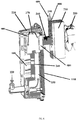
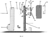
FIGURE 11 is an exploded view of the exemplary cooling device shown inFIGURES 1 ,2 ,3 ,4 ,5 ,6 , and7 wherein part of the tank is not shown in order to more clearly show the other components of the device; and -
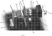
FIGURE 12 is a top perspective exploded view of the exemplary cooling device shown inFIGURE 11 wherein again part of the tank is not shown in order to more clearly show the other components of the device. - A preferred exemplary embodiment of a cooling device 100 is shown in
FIGURE 1 . The exemplary system 100 preferably comprises atank 110 that is connected to awater inlet 120 and awater outlet 130. Thetank 110 may be fabricated from polyethylene or polypropylene in some exemplary embodiments. As can be seen inFIGURE 2 , thetank 110 may be formed using more than one piece. In some embodiments, and as shown inFIGURE 2 , theinlet 120 andoutlet 130 are tube-like structures which permit for the travel of liquid to and from thetank 110. However, it should be understood that in some embodiments, theinlet 120 andoutlet 130 consist of and/or comprise openings defined at least in part by thetank 110 and which permit for liquid to flow into and out of the tank. Those inlet/outlet openings tank 110 to and integrate thetank 110 into a water source such as a water cooler or water fountain.FIGURE 2 illustrates the exemplary cooling device ofFIGURE 1 shown without theinsulation layer 300 so that thetank 110 can more clearly be seen. - As can be seen in
FIGURE 3 , Abaffle 140 is disposed within thetank 110 such that thebaffle 140 defines (preferably in conjunction with the interior of thetank 110 or some other surface) afirst area 150 for receiving water from theinlet 120 and asecond area 160 for providing chilled water to theoutlet 130. Thebaffle 140 does not completely divide thetank 110 such that thefirst area 150 and thesecond area 160 are completely separated but instead, thebaffle 140 permits for water to flow from thefirst area 150 to thesecond area 160 within thetank 110 preferably via at least one opening 170 which exists at and may be defined by the top of the interior of thetank 110 and the top of thebaffle 140. Thebaffle 140 may be fabricated from polyethylene or polypropylene in some exemplary embodiments. - As can be seen in
Figure 5 , at least one, and ideally a plurality of coolingfins 180 is also disposed within thetank 110 such that thefins 180 extend through thebaffle 140 and are at least partially exposed to water in both thefirst area 150 and thesecond area 160. In some embodiments, the coolingfins 180 may be made from anodized aluminum in some exemplary embodiments. Note that inFIGURE 5 , part of the exterior oftank 110 has not been shown in order to more clearly show the configuration of thebaffle 140 in relationship with the coolingfins 180. Each one of the coolingfins 180 has a surface area which can be exposed to water in thetank 110. In preferred embodiments, such as that shown inFIGURE 5 , at least one opening 170, exists about and is defined by at least one of thecold fins 180 and thebaffle 140 such that in traveling fromarea 150 toarea 160 the water is exposed to a substantial surface area of the coolingfins 180. The plurality of coolingfins 180 is held within their desired location within thetank 110 by attachment to the interior wall of thetank 110. As more easily seen inFIGURES 11 and12 , the coolingfins 180 may be part of and/or connected to the wall of thetank 110 via a relativelyflat plate 181 that extends through the wall of thetank 110. In some exemplary embodiments, theplate 181 andfins 180 are extruded/formed as a single piece. In other exemplary embodiments, thefins 180 are individual pieces of material (such as aluminum) that are received by form-fitting grooves defined by theplate 181 and then the sides of the grooves of theplate 181 are crimped in tightly onto thefins 180 holding them in place. As shown inFIGURE 3 , the coolingfins 180 may be in thermal connectivity (directly or indirectly) with dualthermoelectric chips 190 that effectuate the cooling of thefins 180 and thus the cooling of water in thetank 110. - In one exemplary embodiment, the
thermoelectric chips 190 are placed in thermal contact/connectivity with the coolingfins 180 by applying a thin layer of heat sink material 401 (for example, a heat sink paste) between thechips 190 and thespacer block 200 and then applying a force to hold the components together. Preferably, the heat sink material 401 (preferably a compound or thermal paste) is applied between theheat sink 210 and thethermoelectric chips 190 as well as between thechips 190 and thespacer block 200 as well as between thespacer block 200 and the coolingfins 180 and/or the coolingfin plate 181. This preferred exemplary embodiment is shown inFIGURE 11 . The force that holds the assembly together may be generated by one or more screws connected to thetank 110. In another exemplary embodiment, thethermoelectric chips 190 are placed in thermal contact/connectivity with the coolingfins 180 by bonding thechips 190 to the coolingfins 180 and/or the coolingfin plate 181 using a thermal epoxy. This alone is capable of holding these parts together and providing heat conduction between thechips 190 and the coolingfins 180. -
FIGURE 4 more clearly shows how twinthermoelectric chips 190 may be incorporated into the exemplary device 100. In such a configuration, the twinthermoelectric chips 190 spread their cooling effect over a wider area within thetank 110 than would be possible via a single chip or two chips disposed in a different configuration. So, rather than having a very cold spot in the center of a single, larger thermoelectric chip, the heat load can be absorbed more evenly and efficiently by the twochips 190. Similarly, heat can be more evenly and efficiently dissipated from the opposite side of the dual, twin chips. Ideally, the twinthermoelectric chips 190 are positioned such that the heat load is spread over a larger width that is perpendicular to the flow of water within thetank 110. Such a configuration is shown inFIGURE 3 . In alternate embodiments, thethermoelectric chips 190 may be positioned such that the heat load is spread over a larger area that is vertical to the flow of water within thetank 110. However, when such a configuration is utilized, there would be more warm water passing by the width of thethermoelectric chips 190 and the water that contacted thethermoelectric chips 190 would cool as it entered the coolingfins 180 and be cooled sufficiently at the midpoint of thethermoelectric chips 190. As the water continues vertically, the heat exchange would decrease. More heat exchange happens when the water and coolingfins 180 are at a greater temperature difference. Also, the water is cold enough when it reached the midpoint. Cooling it further is not necessary. Thus, such alternate configurations, while possible, do not maximize efficiency. In exemplary embodiments comprising dualthermoelectric chips 190, the twothermoelectric chips 190 are preferably "twin" (i.e. substantially identical to each other) as has been discussed above. But, some exemplary embodiments may use dualthermoelectric chips 190 where the first and second chips are not substantially identical to each other. For example, a first chip may be larger than the second chip. In some exemplary embodiments, there may be three or more thermoelectric chips (they may be arranged similarly to the description regarding dual chip layouts provided herein) which may further increase the cooling performance. Some exemplary embodiments may comprise a single thermoelectric chip, but these embodiments are not preferred for the aforementioned reasons. - As shown in
FIGURE 3 , aspacer block 200 may be positioned between thethermoelectric chips 190 and thetank 110. Thespacer block 200 conducts heat from the coolingfins 180 to thethermoelectric chips 190. In some exemplary embodiments, thespacer block 200 is made from aluminum. Other materials may be used in other exemplary embodiments. It is preferred that the material utilized for thespacer block 200 is rigid and thermally conductive. Thespacer block 200 allows forthicker insulation 300 between theheat sink 210 and coolingfins 180 to reduce heat transfer back to thefins 180 from theheat sink 210. The thicker thespacer 200 the thicker theinsulation 300. It should be appreciated that there is a balance to be struck between the thickness of thespacer block 200 and theinsulation 300 thickness. If thespacer block 200 is made too thick, it will not move heat quickly enough. Thethermoelectric chips 190 are ideally positioned outside of thetank body 110. In a preferred embodiment, and as is shown inFIGURES 3 ,4 ,5 ,6 , and7 , the coolingfins 180 are positioned at an upper part of thebaffle 140 near the at least one opening(s) 170 where water may flow from thefirst area 150 to thesecond area 160. Preferably, as water is received by thetank 110 at theinlet 120, the water flows into thefirst area 150 and cooling of the water may commence due to exposure of the water in thefirst area 150 to at least part of the surface area of the coolingfins 180. As water is drawn from thetank 110 via theoutlet 130, water may flow from thefirst area 150 to thesecond area 160 through the opening(s) 170.FIGURE 6 uses arrows to illustrate the preferred flow of water from theinlet 120 intospace 150 then through the coolingfins 180 and opening(s) 170 tospace 160 where the water is selectively maintained until it is removed from thetank 110 via theoutlet 130. When the coolingfins 180 are disposed at an upper portion of thebaffle 140/tank 110 near the opening, the flowing water may be exposed to some of the surface area of the coolingfins 180 in thefirst area 150 and then also in thesecond area 160 after the water passes through the opening(s) 170 causing relatively quick chilling of the water. - The
thermoelectric chips 190 that provide the cooling to the coolingfins 180 preferably have a first and second side. The first side is cool and is the side which is in connectivity (either direct or indirect) with the coolingfins 180. The second side of thethermoelectric chips 190 is hot and is ideally in connectivity with aheat sink 210. Afan 220 is preferably positioned next to theheat sink 210 such that it can draw air through and cool theheat sink 210, preventing theheat sink 210 from overheating. As shown inFIGURE 1 and also inFIGURE 2 ,insulation 300 may surround or substantially surround thetank 110 and may separate thetank 110 from the warm side of thethermoelectric chips 190, theheat sink 210, and thefan 220. Theinsulation 300 may define at least one opening which receives thespacer block 200 so that thethermoelectric chips 190, theheat sink 210, and thefan 220 may be separated from thetank 110 via theinsulation 300 which will help keep water held in the tank cool. - The exemplary system and methods discussed above, may work in conjunction with a first and second power supply in order to increase efficiency of the cooling of water within the
tank body 110. In such embodiments, a first power supply, is connected to thethermoelectric chips 190 and thefan 220 and is configured to provide a high energy output when more substantial cooling is needed (such as for example, when chilled water has been drawn from thetank 110 and the water volume in thetank 110 is replenished with warmer water received from the inlet 120). A second power supply, is connected to thethermoelectric chips 190 and thefan 220 and is configured to provide a lower energy output when a lesser degree of cooling is needed. In another, preferred, exemplary embodiment, a single printed circuit board ("PCB") 500 may comprise a single power supply that is capable of shifting between high power, low power, and no power outputs. Such an exemplary embodiment is shown inFIGURE 8 . As can be seen, thePCB 500 will preferably include a power connection comprising aline 501, neutral 502, andground 503. In such an exemplary embodiment, the high power output may be utilized when more significant cooling of the water/fluid in thetank 110 is needed while the lower power output may be utilized when a relatively small amount of cooling of water/fluid in thetank 110 is needed. The power supply may be turned off when the ambient temperature of the water/fluid in thetank 110 gets too low and/or when the water in the tank is at a desired temperature and does not need additional cooling. - In an exemplary embodiment comprising a single power supply, a high power output may be approximately 50 Watts (12 Volts Direct Current to the
Thermoelectric Chips 190 and Fan 220), while a low power output may be an output of approximately 4 Watts (3.1 Volts Direct Current to theThermoelectric Chip 190 and 6 Volts of Direct Current to the fan 220). Note that the input power to thePCB 500 is likely greater than the power output by thePCB 500 due to inefficiency. In the exemplary embodiment just discussed, the high power input to thePCB 500 when a high power output is being generated would be approximately 75 Watts while the low power input would be 6.2 Watts. In some exemplary embodiments, the input power to thePCB 500 when a low power output is being generated is always less than 6.6 Watts. More details regarding exemplary power supplies that may be used in conjunction with a cooling device 100 are discussed in more detail below. - In the preferred exemplary embodiment, the system 100 additionally comprises an electronic control that is in connectivity with at least one
temperature sensor 600 that measures (i.e. takes readings of) the water temperature within thetank 110. ThePCB 500 shown inFIGURE 8 comprises a power supply as well as an electronic control.FIGURE 9 illustrates anexemplary temperature sensor 600 that may be utilized to obtain temperature measurements of the water in the tank. This may be enabled by positioning at least part of the temperature sensor inside of thetank 110.FIGURE 10 illustrates the exemplary temperature sensor connected to theexemplary PCB 500. As shown inFIGURES 11 and12 , some exemplary systems may comprise more than onesensor 600 each of which would be in electronic connectivity directly or indirectly with the electronic control and at least one power supply. In such exemplary embodiments, asensor 600 may be received by thefirst area 150 and anothersensor 600 may be received by thesecond area 160. - In preferred embodiments, the electronic control compares the temperature measurement(s) received from the at least one
sensor 600 with a predetermined temperature set point (i.e. the desired temperature of the chilled water in the tank) and sends a corresponding signal to at least one power supply. In exemplary embodiments comprising a first and second power supply, depending on the temperature difference between the water in thetank 110 and the set point, the control will shift between the first and second power supplies to provide enough power to thefan 220 and thethermoelectric chips 190 to pull the water temperature down to the cold water set point, maintain the water at the set point, turn off the power to prevent freeze-ups (which tend to occur when the ambient temperature drops to 65 degrees Fahrenheit or lower), etc. In such an embodiment, the second power source may be utilized to send power to thethermoelectric chips 190 andfan 220 when the temperature of the water in thetank 110 is not highly deviated from the set point (for example, when the water in the tank is only 3 or 4 degrees or less off of the set point temperature). But, if thetemperature sensor 600 obtains a reading of the water and it is detected that the temperature of the water in thetank 110 is more highly deviated from the temperature set point (for example, if the temperature of the water is 7 or more degrees off of the set point temperature), the control can switch to the first power source such that it is then supplying energy to thechips 190 andfan 220. - In exemplary embodiments comprising a single power supply that has the capability of shifting between high power, low power, and off (no power being supplied), the electronic control is preferably capable of obtaining temperature readings from the
temperature sensor 600 and sending signals to the power supply that tell the power supply whether it should provide high power, low power, or no power to thechips 190 and/orfan 220. In some embodiments, the power source only supplies power to thechips 190 andfan 220 when the water is at least a certain temperature above the set point. - In some embodiments the set point may be provided to the electronic control and modified by a system user. In other words, the control may be capable of receiving a set point from a system user and cause the water in the
tank 110 to be maintained at the provided set point by instructing the first and/or second power source to send power to thechips 190 andfan 220. In some embodiments however, the control maintains a set point temperature of water in thetank 110 that is not modified by system users. - Power supplies run most efficiently when they operate at outputs close to the maximum output available. Efficiencies of 75% to 90% are easily achievable. When power supplies operate at low output relative to the maximum output of the power supply, the efficiency can drop to lower than 50%. In the preferred exemplary embodiment of the currently disclosed system 100, the energy required to maintain chilled water within the
tank 110 and the set point is less than 4.5 Watts to the fan and the thermoelectric chips. However, when a new volume of warm water is received into thefirst area 150 of thetank 110 from theinlet 120 and more substantial cooling is needed to pull down the temperature of the water to the set point, the maximum energy needed is closer to 60 Watts. Using a single power source to supply energy for both of these functions would be inefficient and would mean that the power supplied to the electronic control andthermoelectric chips 190 would exceed the EPA Energy threshold. In dual power supply systems, the first power source preferably has a relatively low maximum energy output while the second power source has a relatively high maximum energy. By having dual power supplies, one which is activated to provide a lower energy output for maintaining the set point temperature and one which is activated to provide a higher energy output for pulling down the temperature of the water in thetank 110 for example when new water has been provided to thefirst area 150 via theinlet 120, the EPA energy threshold can be achieved. However, in some exemplary embodiments this can also be achieved by using a singlePCB power supply 500 that has the capability of shifting between a high energy output, a low energy output, and a no energy output feature. - Exemplary power supplies that may be utilized are switching power supplies and/or pulse width modulated supplies. Preferably, the power supplies are in connectivity with an electronic control and are even built on a single printed circuit board (this is preferably the case even in exemplary embodiments comprising dual power supplies). In water cooler systems comprising the present cooling device 100, the circuit board comprising the dual power supplies and/or single power supply and the electronic control would ideally be positioned within the cabinet of the water cooler. There is no specific location within the cabinet where the circuit board must be placed there just needs to be wires that connect the board to the tank 110 (and more specifically to the
thermoelectric chips 190 and fan 220). WhileFigures 1 through 7 do not show the power supplies that may be included with or connect to the system 100, the Figures (see for exampleFIGURES 4 and6 ) do illustrate the wire leads 400 that may be utilized to connect thethermoelectric chips 190 and the fan 220 (seeFIGURE 2 ) to the dual power supplies. - An exemplary embodiment comprises a method of chilling water using an exemplary cooling device as is shown in
FIGURES 1 through 7 and11 through 12 and/or as has been described elsewhere herein. Such a method may comprise one or more or all of the steps of: receiving a volume of fluid within a first area of a tank via an inlet, measuring the temperature of the received fluid, detecting that the temperature of said fluid is above a desired set point, causing power to be sent to two thermoelectric chips the cool sides of which are in thermal connectivity with a plurality of cooling fins that are attached to the tank and which extend into the first area such that the fins come into physical contact with the water in the first area thereby causing chilling of the water. The method may further comprise one or more or all of the steps of: causing the fluid to flow into a second area of the tank via at least one opening that extends between the first and second areas, exposing the fluid to the plurality of cooling fins as it flows through the at least one opening as well as within the second area causing further cooling of the fluid, and removing the chilled fluid from the second area of the tank via an outlet. - Any embodiment of the disclosed system may include any of the optional or preferred features of the other embodiments of the present invention. The exemplary embodiments herein disclosed are not intended to be exhaustive or to unnecessarily limit the scope of the invention. The exemplary embodiments were chosen and described in order to explain the principles of the present invention so that others skilled in the art may practice the invention. Having shown and described exemplary embodiments of the present invention, those skilled in the art will realize that many variations and modifications may be made to affect the described invention. Many of those variations and modifications will provide the same result and fall within the scope of the claimed invention. It is the intention, therefore, to limit the invention only as indicated by the scope of the claims.
Claims (11)
- A device for chilling liquid, the device comprising:a tank (110) for receiving and selectively maintaining a volume of liquid within its interior;an inlet (120) for receiving the volume of liquid into the tank;an outlet (130) which permits for the liquid to be removed from the tank;a baffle (140) disposed within the tank (110) such that a first side of the baffle assists in defining a first area (150) within the tank interior for receiving water from the inlet and a second side of the baffle assists in defining a second area (160) within the tank interior for holding at least some of the liquid before it is removed from the tank through the outlet;at least one opening defined by at least part of the baffle and part of the interior of the tank body wherein said opening extends between the first area and the second area and permits for liquid to travel from the first area to the second area;a plurality of cooling fins (180) connected to the tank wherein each cooling fin extends into the interior of the tank and protrudes through the first side of the baffle to the second side of the baffle such that some of the fins extend into the first area of the tank interior and some of the fins extend into the second area of the tank interior; anda plurality of thermoelectric chips (190) in thermal connectivity with the plurality of cooling fins, and positioned such that a heat load associated with the chips is spread over a width that is perpendicular to the flow of the liquid within the tank.
- The device of claim 1 wherein the plurality of thermoelectric chips (190) comprises:a first thermoelectric chip in connectivity with at least some of the plurality of cooling fins (180); anda second thermoelectric chip in connectivity with at least some of the plurality of cooling fins (180).
- The device of claim 2 wherein the first thermoelectric chip and the second thermoelectric chip each have a width and a height and the first and second chips are positioned next to each other horizontally such that they collectively have a width that is greater than the height of the chips and the width of the thermoelectric chips is placed horizontal to the direction fluid would flow from the first area (150) to the second area (160).
- The device of claim 3 further comprising a thermally conductive spacer block (200) that thermally connects the thermoelectric chips (190) to the plurality of cooling fins (180).
- The device of claim 2 further comprising a thermally conductive spacer block that is positioned between the plurality of thermoelectric chips (190) and the tank and thermally connects the thermoelectric chips to the plurality of cooling fins (180) by applying a thin layer of a heat sink material between the chips and the spacer block and then applying a force to hold the components together.
- The device of claim 1, further comprising:a temperature sensor (600) disposed within the tank such that it may take a temperature reading of fluid selectively stored in said tank;an electronic control in connectivity with said temperature sensor wherein said control obtains temperature readings from the temperature sensor and generates signals based on said readings; andat least one power supply in connectivity with the electronic control wherein said at least one power supply receives the signals generated by the control and is adapted to switch between a high power output and a low power output based on the signals.
- The device of claim 1, wherein the at least one opening is a plurality of openings such that there is an opening defined by the baffle for each one of the plurality of cooling fins (180) and each cooling fin is received by one of the openings such that fluid may travel from the first area (150) to the second area (160) via the plurality of openings gaining exposure to surface area of the cooling fins as it flows through said openings.
- The device of claim 1, wherein the plurality of cooling fins (180) is connected to the tank (110) via a plate (181) which is integral with the fins wherein said plate extends from the interior of the tank (110) to the exterior of the tank.
- The device of claim 1, further comprising a layer of insulation (300) having an inner surface and an outer surface wherein said insulation surrounds the exterior of the tank and defines an opening such that the plurality of thermoelectric chips (190) is positioned at the outer surface of the insulation and the tank is positioned at the inner surface of the insulation.
- The device of claim 1 wherein the plurality of thermoelectric chips (190) is positioned next to each other such that they collectively have a width that is vertical to the direction liquid would flow within the tank as it would flow from the first area (150) to the second area (160).
- The device of claim 1, further comprising an electronic control that is in connectivity with at least one temperature sensor (600) disposed within the tank (110) such that it may obtain temperature readings of water selectively maintained in the tank.
Applications Claiming Priority (2)
| Application Number | Priority Date | Filing Date | Title |
|---|---|---|---|
| US201562248626P | 2015-10-30 | 2015-10-30 | |
| PCT/US2016/059707 WO2017075584A1 (en) | 2015-10-30 | 2016-10-31 | Thermoelectric cooling tank system and methods |
Publications (3)
| Publication Number | Publication Date |
|---|---|
| EP3368837A1 EP3368837A1 (en) | 2018-09-05 |
| EP3368837A4 EP3368837A4 (en) | 2019-05-22 |
| EP3368837B1 true EP3368837B1 (en) | 2020-07-08 |
Family
ID=58630893
Family Applications (1)
| Application Number | Title | Priority Date | Filing Date |
|---|---|---|---|
| EP16861038.4A Active EP3368837B1 (en) | 2015-10-30 | 2016-10-31 | A device for chilling liquid |
Country Status (3)
| Country | Link |
|---|---|
| US (1) | US10794618B2 (en) |
| EP (1) | EP3368837B1 (en) |
| WO (1) | WO2017075584A1 (en) |
Families Citing this family (1)
| Publication number | Priority date | Publication date | Assignee | Title |
|---|---|---|---|---|
| EP3330219A1 (en) * | 2016-11-30 | 2018-06-06 | Anheuser-Busch InBev S.A. | Dispensing apparatus provided with a cooling unit |
Family Cites Families (30)
| Publication number | Priority date | Publication date | Assignee | Title |
|---|---|---|---|---|
| US3008299A (en) * | 1959-04-09 | 1961-11-14 | Carrier Corp | Thermoelectric water cooler |
| US3073127A (en) * | 1961-08-02 | 1963-01-15 | Gen Instrument Corp | Thermoelectric device for controlling the psychrometric condition of a flowing fluid |
| US4055053A (en) * | 1975-12-08 | 1977-10-25 | Elfving Thore M | Thermoelectric water cooler or ice freezer |
| US4711294A (en) * | 1985-08-14 | 1987-12-08 | Jacobs Alphonse F | Temperature and humidity control system |
| US5315830B1 (en) * | 1993-04-14 | 1998-04-07 | Marlow Ind Inc | Modular thermoelectric assembly |
| US5501077A (en) | 1994-05-27 | 1996-03-26 | Springwell Dispensers, Inc. | Thermoelectric water chiller |
| US5609033A (en) * | 1996-01-16 | 1997-03-11 | Chung Ho Nais Incorporation | Water cooling device for water purifiers |
| US5862669A (en) * | 1996-02-15 | 1999-01-26 | Springwell Dispensers, Inc. | Thermoelectric water chiller |
| US5987892A (en) * | 1996-12-27 | 1999-11-23 | Thermovonics Co., Ltd. | Storage box apparatus |
| US6003318A (en) * | 1998-04-28 | 1999-12-21 | Oasis Corporation | Thermoelectric water cooler |
| US6532749B2 (en) * | 1999-09-22 | 2003-03-18 | The Coca-Cola Company | Stirling-based heating and cooling device |
| US6508070B1 (en) * | 2001-01-22 | 2003-01-21 | Palmer Technologies, Inc. | Water chiller |
| US20020162339A1 (en) * | 2001-05-04 | 2002-11-07 | Harrison Howard R. | High performance thermoelectric systems |
| US7278270B2 (en) * | 2004-07-01 | 2007-10-09 | The Coleman Company, Inc. | Insulated container with thermoelectric unit |
| US6895762B1 (en) * | 2004-07-26 | 2005-05-24 | Ching-Yu Lin | Refrigerator with a freezer area and a refrigeration area |
| US7237390B1 (en) * | 2005-04-21 | 2007-07-03 | Lance Nelson | Compact portable beverage cooling system |
| CN1964610A (en) * | 2005-11-11 | 2007-05-16 | 鸿富锦精密工业(深圳)有限公司 | A liquid cooling heat radiator |
| US20080184710A1 (en) | 2007-02-06 | 2008-08-07 | Devilbiss Roger S | Multistage Thermoelectric Water Cooler |
| WO2009111008A1 (en) * | 2008-03-05 | 2009-09-11 | Sheetak, Inc. | Method and apparatus for switched thermoelectric cooling of fluids |
| WO2011008280A1 (en) * | 2009-07-17 | 2011-01-20 | Sheetak Inc. | Heat pipes and thermoelectric cooling devices |
| KR20120076416A (en) | 2010-12-29 | 2012-07-09 | 웅진코웨이주식회사 | Cold water tank and water treatment apparatus having the same |
| EP2807432A1 (en) * | 2011-11-17 | 2014-12-03 | Sheetak, Inc. | Method and apparatus for thermoelectric cooling of fluids |
| WO2013169874A1 (en) * | 2012-05-08 | 2013-11-14 | Sheetak, Inc. | Thermoelectric heat pump |
| KR101501071B1 (en) | 2013-06-28 | 2015-03-11 | 코웨이 주식회사 | Cooling Device for Water Purifier |
| GB201318405D0 (en) * | 2013-10-17 | 2013-12-04 | Gray David | A portable temperature controlled container |
| US9377223B1 (en) * | 2013-11-12 | 2016-06-28 | George L Williamson | Thermos with peltier |
| US9717114B1 (en) * | 2013-11-12 | 2017-07-25 | George L Williamson | Thermos with peltier |
| WO2016077843A1 (en) * | 2014-11-14 | 2016-05-19 | Cauchy Charles J | Heating and cooling technologies |
| US20180252446A1 (en) * | 2017-02-13 | 2018-09-06 | Kenneth Steve Place | Cooler Apparatus, System and Method |
| KR102420992B1 (en) * | 2018-03-13 | 2022-07-15 | 엘지전자 주식회사 | Refrigerator |
-
2016
- 2016-10-31 EP EP16861038.4A patent/EP3368837B1/en active Active
- 2016-10-31 US US15/771,928 patent/US10794618B2/en active Active
- 2016-10-31 WO PCT/US2016/059707 patent/WO2017075584A1/en active Application Filing
Non-Patent Citations (1)
| Title |
|---|
| None * |
Also Published As
| Publication number | Publication date |
|---|---|
| EP3368837A1 (en) | 2018-09-05 |
| US10794618B2 (en) | 2020-10-06 |
| EP3368837A4 (en) | 2019-05-22 |
| US20180306471A1 (en) | 2018-10-25 |
| WO2017075584A1 (en) | 2017-05-04 |
Similar Documents
| Publication | Publication Date | Title |
|---|---|---|
| EP2807432A1 (en) | Method and apparatus for thermoelectric cooling of fluids | |
| US20050178529A1 (en) | Cooling system or electronic apparatus, and electronic apparatus using the same | |
| WO2005036257A1 (en) | Projector | |
| TW201608937A (en) | Thermal clamp apparatus for electronics system | |
| JP2008501926A (en) | Heat exchanger and cooling method | |
| US20110056650A1 (en) | Heat sink | |
| US20070097637A1 (en) | Heat dissipation device | |
| KR20200033154A (en) | Water supply device for pets | |
| US20190327864A1 (en) | Heat sink for a display unit | |
| US7120022B2 (en) | Loop thermosyphon with wicking structure and semiconductor die as evaporator | |
| EP2858464A1 (en) | Electric apparatus | |
| EP3368837B1 (en) | A device for chilling liquid | |
| KR101848151B1 (en) | Small heatsink | |
| TWM243830U (en) | Liquid cooling apparatus | |
| TW201641912A (en) | Heat dissipating apparatus | |
| JP2007012955A (en) | Heat receiving vessel, electronic equipment, and projective display device | |
| CN107979948B (en) | Heat dissipation system and network communication equipment | |
| WO2005084313A2 (en) | Non-uniformly heated power device with fluidic cooling | |
| US20060096300A1 (en) | Water dispenser having thermoelectric cooling chips | |
| US20130199208A1 (en) | Liquid cooling system and method for cooling at least one heat generating component | |
| KR102629742B1 (en) | Cold water supplying system, Drinking water supplying device including the same and Controlling method for the same | |
| KR101524924B1 (en) | Cooling Tank using Thermoelectric Module | |
| JP2004311911A (en) | Water cooling heat sink and water cooling unit | |
| KR102041159B1 (en) | Cold and Hot Water Supplying Apparatus for Mattress | |
| KR20150052935A (en) | a water jacket for cooling heating unit and a cooling tank comprising the same |
Legal Events
| Date | Code | Title | Description |
|---|---|---|---|
| STAA | Information on the status of an ep patent application or granted ep patent |
Free format text: STATUS: THE INTERNATIONAL PUBLICATION HAS BEEN MADE |
|
| PUAI | Public reference made under article 153(3) epc to a published international application that has entered the european phase |
Free format text: ORIGINAL CODE: 0009012 |
|
| STAA | Information on the status of an ep patent application or granted ep patent |
Free format text: STATUS: REQUEST FOR EXAMINATION WAS MADE |
|
| 17P | Request for examination filed |
Effective date: 20180529 |
|
| AK | Designated contracting states |
Kind code of ref document: A1 Designated state(s): AL AT BE BG CH CY CZ DE DK EE ES FI FR GB GR HR HU IE IS IT LI LT LU LV MC MK MT NL NO PL PT RO RS SE SI SK SM TR |
|
| AX | Request for extension of the european patent |
Extension state: BA ME |
|
| DAV | Request for validation of the european patent (deleted) | ||
| DAX | Request for extension of the european patent (deleted) | ||
| A4 | Supplementary search report drawn up and despatched |
Effective date: 20190424 |
|
| RIC1 | Information provided on ipc code assigned before grant |
Ipc: H01L 35/32 20060101ALI20190416BHEP Ipc: B67D 3/00 20060101ALI20190416BHEP Ipc: F25B 21/00 20060101ALI20190416BHEP Ipc: F25B 31/00 20060101ALI20190416BHEP Ipc: H01L 35/00 20060101ALI20190416BHEP Ipc: H01L 35/30 20060101ALI20190416BHEP Ipc: F25B 21/02 20060101AFI20190416BHEP Ipc: F25B 49/00 20060101ALI20190416BHEP Ipc: F25D 31/00 20060101ALI20190416BHEP Ipc: F25B 11/00 20060101ALI20190416BHEP Ipc: B67D 1/08 20060101ALI20190416BHEP |
|
| GRAP | Despatch of communication of intention to grant a patent |
Free format text: ORIGINAL CODE: EPIDOSNIGR1 |
|
| STAA | Information on the status of an ep patent application or granted ep patent |
Free format text: STATUS: GRANT OF PATENT IS INTENDED |
|
| INTG | Intention to grant announced |
Effective date: 20200122 |
|
| GRAS | Grant fee paid |
Free format text: ORIGINAL CODE: EPIDOSNIGR3 |
|
| GRAA | (expected) grant |
Free format text: ORIGINAL CODE: 0009210 |
|
| STAA | Information on the status of an ep patent application or granted ep patent |
Free format text: STATUS: THE PATENT HAS BEEN GRANTED |
|
| AK | Designated contracting states |
Kind code of ref document: B1 Designated state(s): AL AT BE BG CH CY CZ DE DK EE ES FI FR GB GR HR HU IE IS IT LI LT LU LV MC MK MT NL NO PL PT RO RS SE SI SK SM TR |
|
| REG | Reference to a national code |
Ref country code: CH Ref legal event code: EP Ref country code: AT Ref legal event code: REF Ref document number: 1288887 Country of ref document: AT Kind code of ref document: T Effective date: 20200715 |
|
| REG | Reference to a national code |
Ref country code: DE Ref legal event code: R096 Ref document number: 602016039761 Country of ref document: DE |
|
| REG | Reference to a national code |
Ref country code: IE Ref legal event code: FG4D |
|
| REG | Reference to a national code |
Ref country code: LT Ref legal event code: MG4D |
|
| REG | Reference to a national code |
Ref country code: AT Ref legal event code: MK05 Ref document number: 1288887 Country of ref document: AT Kind code of ref document: T Effective date: 20200708 |
|
| REG | Reference to a national code |
Ref country code: NL Ref legal event code: MP Effective date: 20200708 |
|
| PG25 | Lapsed in a contracting state [announced via postgrant information from national office to epo] |
Ref country code: HR Free format text: LAPSE BECAUSE OF FAILURE TO SUBMIT A TRANSLATION OF THE DESCRIPTION OR TO PAY THE FEE WITHIN THE PRESCRIBED TIME-LIMIT Effective date: 20200708 Ref country code: AT Free format text: LAPSE BECAUSE OF FAILURE TO SUBMIT A TRANSLATION OF THE DESCRIPTION OR TO PAY THE FEE WITHIN THE PRESCRIBED TIME-LIMIT Effective date: 20200708 Ref country code: NO Free format text: LAPSE BECAUSE OF FAILURE TO SUBMIT A TRANSLATION OF THE DESCRIPTION OR TO PAY THE FEE WITHIN THE PRESCRIBED TIME-LIMIT Effective date: 20201008 Ref country code: SE Free format text: LAPSE BECAUSE OF FAILURE TO SUBMIT A TRANSLATION OF THE DESCRIPTION OR TO PAY THE FEE WITHIN THE PRESCRIBED TIME-LIMIT Effective date: 20200708 Ref country code: GR Free format text: LAPSE BECAUSE OF FAILURE TO SUBMIT A TRANSLATION OF THE DESCRIPTION OR TO PAY THE FEE WITHIN THE PRESCRIBED TIME-LIMIT Effective date: 20201009 Ref country code: FI Free format text: LAPSE BECAUSE OF FAILURE TO SUBMIT A TRANSLATION OF THE DESCRIPTION OR TO PAY THE FEE WITHIN THE PRESCRIBED TIME-LIMIT Effective date: 20200708 Ref country code: BG Free format text: LAPSE BECAUSE OF FAILURE TO SUBMIT A TRANSLATION OF THE DESCRIPTION OR TO PAY THE FEE WITHIN THE PRESCRIBED TIME-LIMIT Effective date: 20201008 Ref country code: ES Free format text: LAPSE BECAUSE OF FAILURE TO SUBMIT A TRANSLATION OF THE DESCRIPTION OR TO PAY THE FEE WITHIN THE PRESCRIBED TIME-LIMIT Effective date: 20200708 Ref country code: PT Free format text: LAPSE BECAUSE OF FAILURE TO SUBMIT A TRANSLATION OF THE DESCRIPTION OR TO PAY THE FEE WITHIN THE PRESCRIBED TIME-LIMIT Effective date: 20201109 Ref country code: LT Free format text: LAPSE BECAUSE OF FAILURE TO SUBMIT A TRANSLATION OF THE DESCRIPTION OR TO PAY THE FEE WITHIN THE PRESCRIBED TIME-LIMIT Effective date: 20200708 |
|
| PG25 | Lapsed in a contracting state [announced via postgrant information from national office to epo] |
Ref country code: PL Free format text: LAPSE BECAUSE OF FAILURE TO SUBMIT A TRANSLATION OF THE DESCRIPTION OR TO PAY THE FEE WITHIN THE PRESCRIBED TIME-LIMIT Effective date: 20200708 Ref country code: LV Free format text: LAPSE BECAUSE OF FAILURE TO SUBMIT A TRANSLATION OF THE DESCRIPTION OR TO PAY THE FEE WITHIN THE PRESCRIBED TIME-LIMIT Effective date: 20200708 Ref country code: RS Free format text: LAPSE BECAUSE OF FAILURE TO SUBMIT A TRANSLATION OF THE DESCRIPTION OR TO PAY THE FEE WITHIN THE PRESCRIBED TIME-LIMIT Effective date: 20200708 Ref country code: IS Free format text: LAPSE BECAUSE OF FAILURE TO SUBMIT A TRANSLATION OF THE DESCRIPTION OR TO PAY THE FEE WITHIN THE PRESCRIBED TIME-LIMIT Effective date: 20201108 |
|
| PG25 | Lapsed in a contracting state [announced via postgrant information from national office to epo] |
Ref country code: NL Free format text: LAPSE BECAUSE OF FAILURE TO SUBMIT A TRANSLATION OF THE DESCRIPTION OR TO PAY THE FEE WITHIN THE PRESCRIBED TIME-LIMIT Effective date: 20200708 |
|
| REG | Reference to a national code |
Ref country code: DE Ref legal event code: R097 Ref document number: 602016039761 Country of ref document: DE |
|
| PG25 | Lapsed in a contracting state [announced via postgrant information from national office to epo] |
Ref country code: RO Free format text: LAPSE BECAUSE OF FAILURE TO SUBMIT A TRANSLATION OF THE DESCRIPTION OR TO PAY THE FEE WITHIN THE PRESCRIBED TIME-LIMIT Effective date: 20200708 Ref country code: CZ Free format text: LAPSE BECAUSE OF FAILURE TO SUBMIT A TRANSLATION OF THE DESCRIPTION OR TO PAY THE FEE WITHIN THE PRESCRIBED TIME-LIMIT Effective date: 20200708 Ref country code: DK Free format text: LAPSE BECAUSE OF FAILURE TO SUBMIT A TRANSLATION OF THE DESCRIPTION OR TO PAY THE FEE WITHIN THE PRESCRIBED TIME-LIMIT Effective date: 20200708 Ref country code: IT Free format text: LAPSE BECAUSE OF FAILURE TO SUBMIT A TRANSLATION OF THE DESCRIPTION OR TO PAY THE FEE WITHIN THE PRESCRIBED TIME-LIMIT Effective date: 20200708 Ref country code: EE Free format text: LAPSE BECAUSE OF FAILURE TO SUBMIT A TRANSLATION OF THE DESCRIPTION OR TO PAY THE FEE WITHIN THE PRESCRIBED TIME-LIMIT Effective date: 20200708 Ref country code: SM Free format text: LAPSE BECAUSE OF FAILURE TO SUBMIT A TRANSLATION OF THE DESCRIPTION OR TO PAY THE FEE WITHIN THE PRESCRIBED TIME-LIMIT Effective date: 20200708 |
|
| REG | Reference to a national code |
Ref country code: DE Ref legal event code: R119 Ref document number: 602016039761 Country of ref document: DE |
|
| PLBE | No opposition filed within time limit |
Free format text: ORIGINAL CODE: 0009261 |
|
| STAA | Information on the status of an ep patent application or granted ep patent |
Free format text: STATUS: NO OPPOSITION FILED WITHIN TIME LIMIT |
|
| PG25 | Lapsed in a contracting state [announced via postgrant information from national office to epo] |
Ref country code: AL Free format text: LAPSE BECAUSE OF FAILURE TO SUBMIT A TRANSLATION OF THE DESCRIPTION OR TO PAY THE FEE WITHIN THE PRESCRIBED TIME-LIMIT Effective date: 20200708 |
|
| REG | Reference to a national code |
Ref country code: CH Ref legal event code: PL |
|
| 26N | No opposition filed |
Effective date: 20210409 |
|
| PG25 | Lapsed in a contracting state [announced via postgrant information from national office to epo] |
Ref country code: LU Free format text: LAPSE BECAUSE OF NON-PAYMENT OF DUE FEES Effective date: 20201031 Ref country code: MC Free format text: LAPSE BECAUSE OF FAILURE TO SUBMIT A TRANSLATION OF THE DESCRIPTION OR TO PAY THE FEE WITHIN THE PRESCRIBED TIME-LIMIT Effective date: 20200708 Ref country code: SK Free format text: LAPSE BECAUSE OF FAILURE TO SUBMIT A TRANSLATION OF THE DESCRIPTION OR TO PAY THE FEE WITHIN THE PRESCRIBED TIME-LIMIT Effective date: 20200708 |
|
| REG | Reference to a national code |
Ref country code: BE Ref legal event code: MM Effective date: 20201031 |
|
| PG25 | Lapsed in a contracting state [announced via postgrant information from national office to epo] |
Ref country code: DE Free format text: LAPSE BECAUSE OF NON-PAYMENT OF DUE FEES Effective date: 20210501 |
|
| PG25 | Lapsed in a contracting state [announced via postgrant information from national office to epo] |
Ref country code: BE Free format text: LAPSE BECAUSE OF NON-PAYMENT OF DUE FEES Effective date: 20201031 Ref country code: CH Free format text: LAPSE BECAUSE OF NON-PAYMENT OF DUE FEES Effective date: 20201031 Ref country code: LI Free format text: LAPSE BECAUSE OF NON-PAYMENT OF DUE FEES Effective date: 20201031 Ref country code: SI Free format text: LAPSE BECAUSE OF FAILURE TO SUBMIT A TRANSLATION OF THE DESCRIPTION OR TO PAY THE FEE WITHIN THE PRESCRIBED TIME-LIMIT Effective date: 20200708 |
|
| PG25 | Lapsed in a contracting state [announced via postgrant information from national office to epo] |
Ref country code: IE Free format text: LAPSE BECAUSE OF NON-PAYMENT OF DUE FEES Effective date: 20201031 |
|
| PG25 | Lapsed in a contracting state [announced via postgrant information from national office to epo] |
Ref country code: TR Free format text: LAPSE BECAUSE OF FAILURE TO SUBMIT A TRANSLATION OF THE DESCRIPTION OR TO PAY THE FEE WITHIN THE PRESCRIBED TIME-LIMIT Effective date: 20200708 Ref country code: MT Free format text: LAPSE BECAUSE OF FAILURE TO SUBMIT A TRANSLATION OF THE DESCRIPTION OR TO PAY THE FEE WITHIN THE PRESCRIBED TIME-LIMIT Effective date: 20200708 Ref country code: CY Free format text: LAPSE BECAUSE OF FAILURE TO SUBMIT A TRANSLATION OF THE DESCRIPTION OR TO PAY THE FEE WITHIN THE PRESCRIBED TIME-LIMIT Effective date: 20200708 |
|
| PG25 | Lapsed in a contracting state [announced via postgrant information from national office to epo] |
Ref country code: MK Free format text: LAPSE BECAUSE OF FAILURE TO SUBMIT A TRANSLATION OF THE DESCRIPTION OR TO PAY THE FEE WITHIN THE PRESCRIBED TIME-LIMIT Effective date: 20200708 |
|
| P02 | Opt-out of the competence of the unified patent court (upc) changed |
Effective date: 20230529 |
|
| PGFP | Annual fee paid to national office [announced via postgrant information from national office to epo] |
Ref country code: GB Payment date: 20231002 Year of fee payment: 8 |
|
| PGFP | Annual fee paid to national office [announced via postgrant information from national office to epo] |
Ref country code: FR Payment date: 20231023 Year of fee payment: 8 |