EP3368837B1 - Eine vorrichtung zum kühlen von flüssigkeit - Google Patents
Eine vorrichtung zum kühlen von flüssigkeit Download PDFInfo
- Publication number
- EP3368837B1 EP3368837B1 EP16861038.4A EP16861038A EP3368837B1 EP 3368837 B1 EP3368837 B1 EP 3368837B1 EP 16861038 A EP16861038 A EP 16861038A EP 3368837 B1 EP3368837 B1 EP 3368837B1
- Authority
- EP
- European Patent Office
- Prior art keywords
- tank
- area
- water
- chips
- thermoelectric
- Prior art date
- Legal status (The legal status is an assumption and is not a legal conclusion. Google has not performed a legal analysis and makes no representation as to the accuracy of the status listed.)
- Active
Links
Images


Classifications
-
- F—MECHANICAL ENGINEERING; LIGHTING; HEATING; WEAPONS; BLASTING
- F25—REFRIGERATION OR COOLING; COMBINED HEATING AND REFRIGERATION SYSTEMS; HEAT PUMP SYSTEMS; MANUFACTURE OR STORAGE OF ICE; LIQUEFACTION SOLIDIFICATION OF GASES
- F25B—REFRIGERATION MACHINES, PLANTS OR SYSTEMS; COMBINED HEATING AND REFRIGERATION SYSTEMS; HEAT PUMP SYSTEMS
- F25B21/00—Machines, plants or systems, using electric or magnetic effects
- F25B21/02—Machines, plants or systems, using electric or magnetic effects using Peltier effect; using Nernst-Ettinghausen effect
-
- B—PERFORMING OPERATIONS; TRANSPORTING
- B67—OPENING, CLOSING OR CLEANING BOTTLES, JARS OR SIMILAR CONTAINERS; LIQUID HANDLING
- B67D—DISPENSING, DELIVERING OR TRANSFERRING LIQUIDS, NOT OTHERWISE PROVIDED FOR
- B67D1/00—Apparatus or devices for dispensing beverages on draught
- B67D1/08—Details
- B67D1/0857—Cooling arrangements
- B67D1/0869—Cooling arrangements using solid state elements, e.g. Peltier cells
-
- B—PERFORMING OPERATIONS; TRANSPORTING
- B67—OPENING, CLOSING OR CLEANING BOTTLES, JARS OR SIMILAR CONTAINERS; LIQUID HANDLING
- B67D—DISPENSING, DELIVERING OR TRANSFERRING LIQUIDS, NOT OTHERWISE PROVIDED FOR
- B67D3/00—Apparatus or devices for controlling flow of liquids under gravity from storage containers for dispensing purposes
- B67D3/0009—Apparatus or devices for controlling flow of liquids under gravity from storage containers for dispensing purposes provided with cooling arrangements
-
- F—MECHANICAL ENGINEERING; LIGHTING; HEATING; WEAPONS; BLASTING
- F25—REFRIGERATION OR COOLING; COMBINED HEATING AND REFRIGERATION SYSTEMS; HEAT PUMP SYSTEMS; MANUFACTURE OR STORAGE OF ICE; LIQUEFACTION SOLIDIFICATION OF GASES
- F25B—REFRIGERATION MACHINES, PLANTS OR SYSTEMS; COMBINED HEATING AND REFRIGERATION SYSTEMS; HEAT PUMP SYSTEMS
- F25B49/00—Arrangement or mounting of control or safety devices
-
- F—MECHANICAL ENGINEERING; LIGHTING; HEATING; WEAPONS; BLASTING
- F25—REFRIGERATION OR COOLING; COMBINED HEATING AND REFRIGERATION SYSTEMS; HEAT PUMP SYSTEMS; MANUFACTURE OR STORAGE OF ICE; LIQUEFACTION SOLIDIFICATION OF GASES
- F25D—REFRIGERATORS; COLD ROOMS; ICE-BOXES; COOLING OR FREEZING APPARATUS NOT OTHERWISE PROVIDED FOR
- F25D31/00—Other cooling or freezing apparatus
- F25D31/002—Liquid coolers, e.g. beverage cooler
-
- H—ELECTRICITY
- H10—SEMICONDUCTOR DEVICES; ELECTRIC SOLID-STATE DEVICES NOT OTHERWISE PROVIDED FOR
- H10N—ELECTRIC SOLID-STATE DEVICES NOT OTHERWISE PROVIDED FOR
- H10N10/00—Thermoelectric devices comprising a junction of dissimilar materials, i.e. devices exhibiting Seebeck or Peltier effects
- H10N10/10—Thermoelectric devices comprising a junction of dissimilar materials, i.e. devices exhibiting Seebeck or Peltier effects operating with only the Peltier or Seebeck effects
- H10N10/13—Thermoelectric devices comprising a junction of dissimilar materials, i.e. devices exhibiting Seebeck or Peltier effects operating with only the Peltier or Seebeck effects characterised by the heat-exchanging means at the junction
-
- H—ELECTRICITY
- H10—SEMICONDUCTOR DEVICES; ELECTRIC SOLID-STATE DEVICES NOT OTHERWISE PROVIDED FOR
- H10N—ELECTRIC SOLID-STATE DEVICES NOT OTHERWISE PROVIDED FOR
- H10N10/00—Thermoelectric devices comprising a junction of dissimilar materials, i.e. devices exhibiting Seebeck or Peltier effects
- H10N10/10—Thermoelectric devices comprising a junction of dissimilar materials, i.e. devices exhibiting Seebeck or Peltier effects operating with only the Peltier or Seebeck effects
- H10N10/17—Thermoelectric devices comprising a junction of dissimilar materials, i.e. devices exhibiting Seebeck or Peltier effects operating with only the Peltier or Seebeck effects characterised by the structure or configuration of the cell or thermocouple forming the device
-
- F—MECHANICAL ENGINEERING; LIGHTING; HEATING; WEAPONS; BLASTING
- F25—REFRIGERATION OR COOLING; COMBINED HEATING AND REFRIGERATION SYSTEMS; HEAT PUMP SYSTEMS; MANUFACTURE OR STORAGE OF ICE; LIQUEFACTION SOLIDIFICATION OF GASES
- F25B—REFRIGERATION MACHINES, PLANTS OR SYSTEMS; COMBINED HEATING AND REFRIGERATION SYSTEMS; HEAT PUMP SYSTEMS
- F25B2321/00—Details of machines, plants or systems, using electric or magnetic effects
- F25B2321/02—Details of machines, plants or systems, using electric or magnetic effects using Peltier effects; using Nernst-Ettinghausen effects
- F25B2321/023—Mounting details thereof
Definitions
- Exemplary embodiments relate to devices and methods for cooling liquids, such as water for example, using a tank comprising a unique combination of cooling fins and a baffle that work in conjunction with a first and a second thermoelectric chip.
- a preferred exemplary embodiment comprises a cooling tank that receives and selectively maintains a volume of water from a water inlet and that provides chilled water to a water outlet, a baffle having a first side and a second side and that is disposed within the tank such that water within the tank is received from the inlet into a first area of the tank that is largely defined by the first side of the baffle and water is removed from the tank by the water outlet from a second area of the tank that is largely defined by the second side of the baffle, a plurality of cooling fins that extend from the first side of the baffle to the second side of the baffle, and dual thermoelectric chips in connectivity with the cooling fins such that heat may be drawn from the fins by the thermoelectric chips causing the volume of water within the tank - on both sides of
- thermoelectric cooling uses the Peltier effect to create a heat flux between the junction of two different types of materials.
- a thermoelectric cooler is a solid-state active heat pump which transfers heat from one side of the device to the other with consumption of electrical energy, depending on the direction of the current.
- Thermoelectric water coolers are well known and have been on the market for more than 20 years. The advantages to thermoelectric water coolers are durability, their lightweight, and compact size as compared to more traditional compressor-driven cooling systems. For example, there are provided cold water tanks having a tank main body divided into a first body and a second body, and a water treatment apparatus cooling a power supply device provided to cool the cold water tank without using an air blower.
- the cold water tank includes: a tank main body including a first body and a second body combined to form an internal space therein; and a cooling unit including a thermoelectric module cooling water accommodated within the tank main body, wherein the first body is made of a synthetic resin material, and the second main body is made of a metallic material.
- thermoelectric water coolers are that they are not as energy efficient as compression-driven cooling systems and they are relatively slow in chilling water.
- EPA Environmental Protection Agency
- WO 2012/091499 A2 discloses a device for chilling liquid, the device comprising: a tank for receiving and selectively maintaining a volume of liquid within its interior; an inlet for receiving the volume of liquid into the tank; an outlet which permits for the liquid to be removed from the tank; a baffle disposed within the tank such that a first side of the baffle assists in defining a first area within the tank interior for receiving water from the inlet and a second side of the baffle assists in defining a second area within the tank interior for holding at least some of the liquid before it is removed from the tank through the outlet; at least one opening defined by at least part of the baffle and part of the interior of the tank body wherein said opening extends between the first area and the second area and permits for liquid to travel from the first area to the second area; a plurality of cooling members; at least one thermoelectric chip in thermal connectivity with the cooling members.
- a device according to claim 1 for chilling liquid is provided.
- the devices according to claims 1-11 provide an energy efficient thermoelectric cooler that solves the problems inherent in the known thermoelectric cooling systems.
- a cooling tank is connected to a water inlet and a water outlet.
- a baffle is disposed within the tank such that it creates a first area for receiving water from the inlet and a second area for providing chilled water to the outlet.
- the baffle does not completely divide the tank but instead permits for water to flow from the first area to the second area within the tank preferably at an opening (or more than one opening in some embodiments) which exists at and is defined by the top of the interior of the tank and the top of the baffle.
- a plurality of cooling fins are also disposed within the tank such that they extend through the baffle and are at least partially exposed to water in both the first area and the second area.
- the plurality of cooling fins are in connectivity with a plurality of thermoelectric chips, but preferably dual thermoelectric chips, that effectuate the cooling of the fins and positioned such that a heat load associated with the chips is spread over a width that is perpendicular to the flow of the liquid within the tank.
- the thermoelectric chips are ideally positioned outside of the tank.
- the cooling fins are positioned at an upper part of the baffle near the opening(s) where water may flow from the first area to the second area.
- the water flows into the first area and cooling of the water may commence due to exposure of at least some of the water in the first area to the cooling fins.
- water may flow from the first area to the second area through the opening(s).
- the cooling fins are disposed at an upper portion of the baffle/tank near the opening(s)
- the cooling fins are actually received by the openings which permit for water to travel from the first area to the second area.
- Such an embodiment permits for flowing water to be chilled as it travels between the first and second areas of the tank.
- thermoelectric chips that provide the cooling to the cooling fins preferably each have a first and second side.
- the first side is cool and is the side which is in connectivity (either direct or indirect) with the cooling fins.
- the second side of the thermoelectric chips is hot and is ideally in connectivity with a heat sink.
- a fan is preferably positioned next to the heat sink such that it can draw air through and cool the heat sink, preventing the heat sink from overheating.
- a benefit of exemplary embodiments of the present invention is that most of the chilled water within the tank can be removed from the tank (via the outlet) with less warming effect of incoming water (from the inlet) resulting in more chilled water volume within the tank that is available for drinking.
- This exemplary thermoelectric cooling system may additionally comprise a first and a second power supply.
- the first power supply preferably provides a high energy output to the fan and thermoelectric chip(s) when more cooling is needed such as for example when there is a need to cool incoming water that has been received from the inlet such that the water within the tank is chilled to a desired set point.
- the second power supply preferably provides a low power output to the fan and thermoelectric chips and can be utilized when less cooling is needed such as, for example, when water that has been in the tank for some time needs periodic cooling to maintain the water at the desired chilled set point. Utilization of dual power supplies increases the efficiency of the exemplary thermoelectric cooling device and assists the device in meeting energy star guidelines.
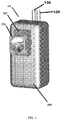
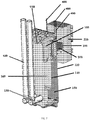
- FIGURE 1 A preferred exemplary embodiment of a cooling device 100 is shown in FIGURE 1 .
- the exemplary system 100 preferably comprises a tank 110 that is connected to a water inlet 120 and a water outlet 130.
- the tank 110 may be fabricated from polyethylene or polypropylene in some exemplary embodiments. As can be seen in FIGURE 2 , the tank 110 may be formed using more than one piece.
- the inlet 120 and outlet 130 are tube-like structures which permit for the travel of liquid to and from the tank 110.
- the inlet 120 and outlet 130 consist of and/or comprise openings defined at least in part by the tank 110 and which permit for liquid to flow into and out of the tank.
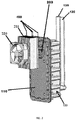
- FIGURE 2 illustrates the exemplary cooling device of FIGURE 1 shown without the insulation layer 300 so that the tank 110 can more clearly be seen.
- a baffle 140 is disposed within the tank 110 such that the baffle 140 defines (preferably in conjunction with the interior of the tank 110 or some other surface) a first area 150 for receiving water from the inlet 120 and a second area 160 for providing chilled water to the outlet 130.
- the baffle 140 does not completely divide the tank 110 such that the first area 150 and the second area 160 are completely separated but instead, the baffle 140 permits for water to flow from the first area 150 to the second area 160 within the tank 110 preferably via at least one opening 170 which exists at and may be defined by the top of the interior of the tank 110 and the top of the baffle 140.
- the baffle 140 may be fabricated from polyethylene or polypropylene in some exemplary embodiments.
- cooling fins 180 are also disposed within the tank 110 such that the fins 180 extend through the baffle 140 and are at least partially exposed to water in both the first area 150 and the second area 160.
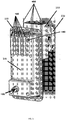
- the cooling fins 180 may be made from anodized aluminum in some exemplary embodiments. Note that in FIGURE 5 , part of the exterior of tank 110 has not been shown in order to more clearly show the configuration of the baffle 140 in relationship with the cooling fins 180.
- Each one of the cooling fins 180 has a surface area which can be exposed to water in the tank 110.
- At least one opening 170 exists about and is defined by at least one of the cold fins 180 and the baffle 140 such that in traveling from area 150 to area 160 the water is exposed to a substantial surface area of the cooling fins 180.
- the plurality of cooling fins 180 is held within their desired location within the tank 110 by attachment to the interior wall of the tank 110.
- the cooling fins 180 may be part of and/or connected to the wall of the tank 110 via a relatively flat plate 181 that extends through the wall of the tank 110.
- the plate 181 and fins 180 are extruded/formed as a single piece.
- the fins 180 are individual pieces of material (such as aluminum) that are received by form-fitting grooves defined by the plate 181 and then the sides of the grooves of the plate 181 are crimped in tightly onto the fins 180 holding them in place.
- the cooling fins 180 may be in thermal connectivity (directly or indirectly) with dual thermoelectric chips 190 that effectuate the cooling of the fins 180 and thus the cooling of water in the tank 110.
- thermoelectric chips 190 are placed in thermal contact/connectivity with the cooling fins 180 by applying a thin layer of heat sink material 401 (for example, a heat sink paste) between the chips 190 and the spacer block 200 and then applying a force to hold the components together.
- heat sink material 401 preferably a compound or thermal paste
- the heat sink material 401 is applied between the heat sink 210 and the thermoelectric chips 190 as well as between the chips 190 and the spacer block 200 as well as between the spacer block 200 and the cooling fins 180 and/or the cooling fin plate 181.
- the force that holds the assembly together may be generated by one or more screws connected to the tank 110.
- thermoelectric chips 190 are placed in thermal contact/connectivity with the cooling fins 180 by bonding the chips 190 to the cooling fins 180 and/or the cooling fin plate 181 using a thermal epoxy. This alone is capable of holding these parts together and providing heat conduction between the chips 190 and the cooling fins 180.
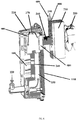
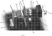
- FIGURE 4 more clearly shows how twin thermoelectric chips 190 may be incorporated into the exemplary device 100.
- the twin thermoelectric chips 190 spread their cooling effect over a wider area within the tank 110 than would be possible via a single chip or two chips disposed in a different configuration. So, rather than having a very cold spot in the center of a single, larger thermoelectric chip, the heat load can be absorbed more evenly and efficiently by the two chips 190. Similarly, heat can be more evenly and efficiently dissipated from the opposite side of the dual, twin chips.
- the twin thermoelectric chips 190 are positioned such that the heat load is spread over a larger width that is perpendicular to the flow of water within the tank 110. Such a configuration is shown in FIGURE 3 .
- thermoelectric chips 190 may be positioned such that the heat load is spread over a larger area that is vertical to the flow of water within the tank 110.
- the heat exchange would decrease. More heat exchange happens when the water and cooling fins 180 are at a greater temperature difference. Also, the water is cold enough when it reached the midpoint. Cooling it further is not necessary.
- such alternate configurations while possible, do not maximize efficiency.
- thermoelectric chips 190 are preferably "twin" (i.e. substantially identical to each other) as has been discussed above. But, some exemplary embodiments may use dual thermoelectric chips 190 where the first and second chips are not substantially identical to each other. For example, a first chip may be larger than the second chip. In some exemplary embodiments, there may be three or more thermoelectric chips (they may be arranged similarly to the description regarding dual chip layouts provided herein) which may further increase the cooling performance. Some exemplary embodiments may comprise a single thermoelectric chip, but these embodiments are not preferred for the aforementioned reasons.
- a spacer block 200 may be positioned between the thermoelectric chips 190 and the tank 110.
- the spacer block 200 conducts heat from the cooling fins 180 to the thermoelectric chips 190.
- the spacer block 200 is made from aluminum. Other materials may be used in other exemplary embodiments. It is preferred that the material utilized for the spacer block 200 is rigid and thermally conductive.
- the spacer block 200 allows for thicker insulation 300 between the heat sink 210 and cooling fins 180 to reduce heat transfer back to the fins 180 from the heat sink 210. The thicker the spacer 200 the thicker the insulation 300. It should be appreciated that there is a balance to be struck between the thickness of the spacer block 200 and the insulation 300 thickness.
- thermoelectric chips 190 are ideally positioned outside of the tank body 110.
- the cooling fins 180 are positioned at an upper part of the baffle 140 near the at least one opening(s) 170 where water may flow from the first area 150 to the second area 160.
- the water flows into the first area 150 and cooling of the water may commence due to exposure of the water in the first area 150 to at least part of the surface area of the cooling fins 180.
- FIGURE 6 uses arrows to illustrate the preferred flow of water from the inlet 120 into space 150 then through the cooling fins 180 and opening(s) 170 to space 160 where the water is selectively maintained until it is removed from the tank 110 via the outlet 130.
- the cooling fins 180 are disposed at an upper portion of the baffle 140 /tank 110 near the opening, the flowing water may be exposed to some of the surface area of the cooling fins 180 in the first area 150 and then also in the second area 160 after the water passes through the opening(s) 170 causing relatively quick chilling of the water.
- the thermoelectric chips 190 that provide the cooling to the cooling fins 180 preferably have a first and second side.
- the first side is cool and is the side which is in connectivity (either direct or indirect) with the cooling fins 180.
- the second side of the thermoelectric chips 190 is hot and is ideally in connectivity with a heat sink 210.
- a fan 220 is preferably positioned next to the heat sink 210 such that it can draw air through and cool the heat sink 210, preventing the heat sink 210 from overheating.
- insulation 300 may surround or substantially surround the tank 110 and may separate the tank 110 from the warm side of the thermoelectric chips 190, the heat sink 210, and the fan 220.
- the insulation 300 may define at least one opening which receives the spacer block 200 so that the thermoelectric chips 190, the heat sink 210, and the fan 220 may be separated from the tank 110 via the insulation 300 which will help keep water held in the tank cool.
- a first power supply is connected to the thermoelectric chips 190 and the fan 220 and is configured to provide a high energy output when more substantial cooling is needed (such as for example, when chilled water has been drawn from the tank 110 and the water volume in the tank 110 is replenished with warmer water received from the inlet 120 ).
- a second power supply is connected to the thermoelectric chips 190 and the fan 220 and is configured to provide a lower energy output when a lesser degree of cooling is needed.
- a single printed circuit board (“PCB”) 500 may comprise a single power supply that is capable of shifting between high power, low power, and no power outputs.
- the PCB 500 will preferably include a power connection comprising a line 501, neutral 502, and ground 503.
- the high power output may be utilized when more significant cooling of the water/fluid in the tank 110 is needed while the lower power output may be utilized when a relatively small amount of cooling of water/fluid in the tank 110 is needed.
- the power supply may be turned off when the ambient temperature of the water/fluid in the tank 110 gets too low and/or when the water in the tank is at a desired temperature and does not need additional cooling.
- a high power output may be approximately 50 Watts (12 Volts Direct Current to the Thermoelectric Chips 190 and Fan 220 ), while a low power output may be an output of approximately 4 Watts (3.1 Volts Direct Current to the Thermoelectric Chip 190 and 6 Volts of Direct Current to the fan 220 ).
- the input power to the PCB 500 is likely greater than the power output by the PCB 500 due to inefficiency.
- the high power input to the PCB 500 when a high power output is being generated would be approximately 75 Watts while the low power input would be 6.2 Watts.
- the input power to the PCB 500 when a low power output is being generated is always less than 6.6 Watts. More details regarding exemplary power supplies that may be used in conjunction with a cooling device 100 are discussed in more detail below.
- the system 100 additionally comprises an electronic control that is in connectivity with at least one temperature sensor 600 that measures (i.e. takes readings of) the water temperature within the tank 110.
- the PCB 500 shown in FIGURE 8 comprises a power supply as well as an electronic control.
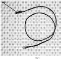
- FIGURE 9 illustrates an exemplary temperature sensor 600 that may be utilized to obtain temperature measurements of the water in the tank. This may be enabled by positioning at least part of the temperature sensor inside of the tank 110.
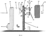
- FIGURE 10 illustrates the exemplary temperature sensor connected to the exemplary PCB 500.
- some exemplary systems may comprise more than one sensor 600 each of which would be in electronic connectivity directly or indirectly with the electronic control and at least one power supply.
- a sensor 600 may be received by the first area 150 and another sensor 600 may be received by the second area 160.
- the electronic control compares the temperature measurement(s) received from the at least one sensor 600 with a predetermined temperature set point (i.e. the desired temperature of the chilled water in the tank) and sends a corresponding signal to at least one power supply.
- a predetermined temperature set point i.e. the desired temperature of the chilled water in the tank
- the control will shift between the first and second power supplies to provide enough power to the fan 220 and the thermoelectric chips 190 to pull the water temperature down to the cold water set point, maintain the water at the set point, turn off the power to prevent freeze-ups (which tend to occur when the ambient temperature drops to 65 degrees Fahrenheit or lower), etc.
- the second power source may be utilized to send power to the thermoelectric chips 190 and fan 220 when the temperature of the water in the tank 110 is not highly deviated from the set point (for example, when the water in the tank is only 3 or 4 degrees or less off of the set point temperature). But, if the temperature sensor 600 obtains a reading of the water and it is detected that the temperature of the water in the tank 110 is more highly deviated from the temperature set point (for example, if the temperature of the water is 7 or more degrees off of the set point temperature), the control can switch to the first power source such that it is then supplying energy to the chips 190 and fan 220.
- the electronic control is preferably capable of obtaining temperature readings from the temperature sensor 600 and sending signals to the power supply that tell the power supply whether it should provide high power, low power, or no power to the chips 190 and/or fan 220.
- the power source only supplies power to the chips 190 and fan 220 when the water is at least a certain temperature above the set point.
- the set point may be provided to the electronic control and modified by a system user.
- the control may be capable of receiving a set point from a system user and cause the water in the tank 110 to be maintained at the provided set point by instructing the first and/or second power source to send power to the chips 190 and fan 220.
- the control maintains a set point temperature of water in the tank 110 that is not modified by system users.
- Power supplies run most efficiently when they operate at outputs close to the maximum output available. Efficiencies of 75% to 90% are easily achievable. When power supplies operate at low output relative to the maximum output of the power supply, the efficiency can drop to lower than 50%. In the preferred exemplary embodiment of the currently disclosed system 100, the energy required to maintain chilled water within the tank 110 and the set point is less than 4.5 Watts to the fan and the thermoelectric chips. However, when a new volume of warm water is received into the first area 150 of the tank 110 from the inlet 120 and more substantial cooling is needed to pull down the temperature of the water to the set point, the maximum energy needed is closer to 60 Watts.
- the first power source preferably has a relatively low maximum energy output while the second power source has a relatively high maximum energy.
- the EPA energy threshold can be achieved.
- this can also be achieved by using a single PCB power supply 500 that has the capability of shifting between a high energy output, a low energy output, and a no energy output feature.
- Exemplary power supplies that may be utilized are switching power supplies and/or pulse width modulated supplies.
- the power supplies are in connectivity with an electronic control and are even built on a single printed circuit board (this is preferably the case even in exemplary embodiments comprising dual power supplies).
- the circuit board comprising the dual power supplies and/or single power supply and the electronic control would ideally be positioned within the cabinet of the water cooler. There is no specific location within the cabinet where the circuit board must be placed there just needs to be wires that connect the board to the tank 110 (and more specifically to the thermoelectric chips 190 and fan 220 ).
- Figures 1 through 7 do not show the power supplies that may be included with or connect to the system 100
- the Figures do illustrate the wire leads 400 that may be utilized to connect the thermoelectric chips 190 and the fan 220 (see FIGURE 2 ) to the dual power supplies.
- An exemplary embodiment comprises a method of chilling water using an exemplary cooling device as is shown in FIGURES 1 through 7 and 11 through 12 and/or as has been described elsewhere herein.
- Such a method may comprise one or more or all of the steps of: receiving a volume of fluid within a first area of a tank via an inlet, measuring the temperature of the received fluid, detecting that the temperature of said fluid is above a desired set point, causing power to be sent to two thermoelectric chips the cool sides of which are in thermal connectivity with a plurality of cooling fins that are attached to the tank and which extend into the first area such that the fins come into physical contact with the water in the first area thereby causing chilling of the water.
- the method may further comprise one or more or all of the steps of: causing the fluid to flow into a second area of the tank via at least one opening that extends between the first and second areas, exposing the fluid to the plurality of cooling fins as it flows through the at least one opening as well as within the second area causing further cooling of the fluid, and removing the chilled fluid from the second area of the tank via an outlet.
- any embodiment of the disclosed system may include any of the optional or preferred features of the other embodiments of the present invention.
- the exemplary embodiments herein disclosed are not intended to be exhaustive or to unnecessarily limit the scope of the invention.
- the exemplary embodiments were chosen and described in order to explain the principles of the present invention so that others skilled in the art may practice the invention. Having shown and described exemplary embodiments of the present invention, those skilled in the art will realize that many variations and modifications may be made to affect the described invention. Many of those variations and modifications will provide the same result and fall within the scope of the claimed invention. It is the intention, therefore, to limit the invention only as indicated by the scope of the claims.
Landscapes
- Engineering & Computer Science (AREA)
- Mechanical Engineering (AREA)
- Physics & Mathematics (AREA)
- Thermal Sciences (AREA)
- General Engineering & Computer Science (AREA)
- Chemical & Material Sciences (AREA)
- Combustion & Propulsion (AREA)
- Devices That Are Associated With Refrigeration Equipment (AREA)
Claims (11)
- Vorrichtung zum Kühlen von Flüssigkeit, die Vorrichtung umfassend:einen Tank (110) zum Aufnehmen und selektiven Aufrechterhalten eines Flüssigkeitsvolumens in seinem Inneren;einen Einlass (120) zum Aufnehmen des Flüssigkeitsvolumens in den Tank;einen Auslass (130), der es ermöglicht, die Flüssigkeit aus dem Tank zu entfernen;eine Trennwand (140), die in dem Tank (110) derart angeordnet ist, dass eine erste Seite der Trennwand beim Definieren eines ersten Bereichs (150) innerhalb des Tankinneren zum Aufnehmen von Wasser vom Einlass hilft und eine zweite Seite der Trennwand beim Definieren eines zweiten Bereichs (160) innerhalb des Tankinneren zum Halten von mindestens einem Teil der Flüssigkeit hilft, bevor sie durch den Auslass aus dem Tank entfernt wird;mindestens eine Öffnung, die durch mindestens einen Teil der Trennwand und einen Teil des Inneren des Tankkörpers definiert ist, wobei sich die Öffnung zwischen dem ersten und dem zweiten Bereich erstreckt und ermöglicht, dass Flüssigkeit vom ersten zum zweiten Bereich gelangt;eine Vielzahl von Kühlrippen (180), die mit dem Tank verbunden sind, wobei sich jede Kühlrippe in das Innere des Tanks erstreckt und durch die erste Seite der Trennwand zur zweiten Seite der Trennwand vorsteht, sodass sich einige der Rippen in den ersten Bereich des Tankinneren und einige der Rippen sich in den zweiten Bereich des Tankinneren erstrecken; undeine Vielzahl von thermoelektrischen Chips (190), die wärmeleitend mit einer Vielzahl von Kühlrippen verbunden und so positioniert sind, dass eine mit den Chips verbundene Wärmebelastung über eine Breite verteilt ist, die senkrecht zum Flüssigkeitsstrom innerhalb des Tanks ausgerichtet ist.
- Vorrichtung nach Anspruch 1, wobei die Vielzahl von thermoelektrischen Chips (190) umfassen:einen ersten thermoelektrischen Chip in Verbindung mit mindestens einem Teil der Vielzahl von Kühlrippen (180); undeinen zweiten thermoelektrischen Chip in Verbindung mit mindestens einem Teil der Vielzahl von Kühlrippen (180).
- Vorrichtung nach Anspruch 2, wobei der erste und der zweite thermoelektrische Chip jeweils eine Breite und eine Höhe aufweisen, und der erste und der zweite Chip nebeneinander horizontal positioniert sind, sodass sie zusammen eine Breite aufweisen, die größer ist als die Höhe der Chips und die Breite der thermoelektrischen Chips horizontal zu der Richtung angeordnet ist, in der das Fluid vom ersten Bereich (150) zum zweiten Bereich (160) fließen würde.
- Vorrichtung nach Anspruch 3 ferner umfassend einen wärmeleitenden Abstandsblock (200), der die thermoelektrischen Chips (190) an die Vielzahl von Kühlrippen (180) wärmeleitend verbindet.
- Vorrichtung nach Anspruch 2, ferner umfassend einen wärmeleitenden Abstandsblock, der zwischen der Vielzahl von thermoelektrischen Chips (190) und dem Tank positioniert ist, und die thermoelektrischen Chips mit der Vielzahl von Kühlrippen (180) durch Aufbringen einer dünnen Schicht eines Kühlkörpermaterials zwischen den Chips und dem Abstandsblock und anschließendes Aufbringen einer Kraft, um die Komponenten zusammenzuhalten, wärmeleitend verbindet.
- Vorrichtung nach Anspruch 1, ferner umfassend:einen Temperatursensor (600), der im Tank so angeordnet ist, dass er eine Temperaturmessung des in dem Tank selektiv gespeicherten Fluids durchführen kann;eine elektronische Steuerung in Verbindung mit dem Temperatursensor, wobei die Steuerung Temperaturmesswerte vom Temperatursensor erhält und Signale basierend auf den Messwerten erzeugt; undmindestens eine Stromversorgung in Verbindung mit der elektronischen Steuerung, wobei die mindestens eine Stromversorgung die von der Steuerung erzeugten Signale empfängt und angepasst ist, um basierend auf den Signalen zwischen einer hohen Leistungsabgabe und einer niedrigen Leistungsabgabe umzuschalten.
- Vorrichtung nach Anspruch 1, wobei die mindestens eine Öffnung eine Vielzahl von Öffnungen ist, sodass eine Öffnung durch die Trennwand für jede von der Vielzahl von Kühlrippen (180) definiert wird und jede Kühlrippe durch eine der Öffnungen aufgenommen wird, sodass Fluid vom ersten Bereich (150) zu dem zweiten Bereich (160) über die Vielzahl von Öffnungen gelangen kann und der Oberfläche der Kühlrippen ausgesetzt wird, wenn es durch diese Öffnungen fließt.
- Vorrichtung nach Anspruch 1, wobei die Vielzahl von Kühlrippen (180) mit dem Tank (110) über eine Platte (181) verbunden sind, die einstückig mit den Rippen ausgebildet ist, wobei sich die Platte aus dem Inneren des Tanks (110) zu der Außenseite des Tanks erstreckt.
- Vorrichtung nach Anspruch 1, ferner umfassend eine Isolationsschicht (300) mit einer Innenfläche und einer Außenfläche, wobei die Isolierung die Außenseite des Tanks umgibt und eine Öffnung derart definiert, dass die Vielzahl von thermoelektrischen Chips (190) an der Außenfläche der Isolierung positioniert sind und der Tank an der Innenfläche der Isolierung positioniert ist.
- Vorrichtung nach Anspruch 1, wobei die Vielzahl von thermoelektrischen Chips (190) nebeneinander positioniert sind, sodass sie zusammen eine Breite aufweisen, die vertikal zur Richtung ist, in der die Flüssigkeit innerhalb des Tanks fließen würde, wie sie von dem ersten Bereich (150) zu dem zweiten Bereich (160) fließen würde.
- Vorrichtung nach Anspruch 1, ferner umfassend eine elektronische Steuerung, die mit mindestens einem im Tank (110) angeordneten Temperatursensor (600) in Verbindung steht, sodass er Temperaturmesswerte von Wasser erhalten kann, das selektiv im Tank gehalten wird.
Applications Claiming Priority (2)
| Application Number | Priority Date | Filing Date | Title |
|---|---|---|---|
| US201562248626P | 2015-10-30 | 2015-10-30 | |
| PCT/US2016/059707 WO2017075584A1 (en) | 2015-10-30 | 2016-10-31 | Thermoelectric cooling tank system and methods |
Publications (3)
| Publication Number | Publication Date |
|---|---|
| EP3368837A1 EP3368837A1 (de) | 2018-09-05 |
| EP3368837A4 EP3368837A4 (de) | 2019-05-22 |
| EP3368837B1 true EP3368837B1 (de) | 2020-07-08 |
Family
ID=58630893
Family Applications (1)
| Application Number | Title | Priority Date | Filing Date |
|---|---|---|---|
| EP16861038.4A Active EP3368837B1 (de) | 2015-10-30 | 2016-10-31 | Eine vorrichtung zum kühlen von flüssigkeit |
Country Status (3)
| Country | Link |
|---|---|
| US (1) | US10794618B2 (de) |
| EP (1) | EP3368837B1 (de) |
| WO (1) | WO2017075584A1 (de) |
Families Citing this family (1)
| Publication number | Priority date | Publication date | Assignee | Title |
|---|---|---|---|---|
| EP3330219A1 (de) * | 2016-11-30 | 2018-06-06 | Anheuser-Busch InBev S.A. | Mit einer kühleinheit ausgestattete ausgabevorrichtung |
Family Cites Families (30)
| Publication number | Priority date | Publication date | Assignee | Title |
|---|---|---|---|---|
| US3008299A (en) * | 1959-04-09 | 1961-11-14 | Carrier Corp | Thermoelectric water cooler |
| US3073127A (en) * | 1961-08-02 | 1963-01-15 | Gen Instrument Corp | Thermoelectric device for controlling the psychrometric condition of a flowing fluid |
| US4055053A (en) * | 1975-12-08 | 1977-10-25 | Elfving Thore M | Thermoelectric water cooler or ice freezer |
| US4711294A (en) * | 1985-08-14 | 1987-12-08 | Jacobs Alphonse F | Temperature and humidity control system |
| US5315830B1 (en) * | 1993-04-14 | 1998-04-07 | Marlow Ind Inc | Modular thermoelectric assembly |
| US5501077A (en) * | 1994-05-27 | 1996-03-26 | Springwell Dispensers, Inc. | Thermoelectric water chiller |
| US5609033A (en) * | 1996-01-16 | 1997-03-11 | Chung Ho Nais Incorporation | Water cooling device for water purifiers |
| US5862669A (en) * | 1996-02-15 | 1999-01-26 | Springwell Dispensers, Inc. | Thermoelectric water chiller |
| EP0851187A3 (de) * | 1996-12-27 | 1998-08-19 | Thermovonics Co., Ltd | Aufbewarungskastengerät |
| US6003318A (en) * | 1998-04-28 | 1999-12-21 | Oasis Corporation | Thermoelectric water cooler |
| US6532749B2 (en) * | 1999-09-22 | 2003-03-18 | The Coca-Cola Company | Stirling-based heating and cooling device |
| US6508070B1 (en) * | 2001-01-22 | 2003-01-21 | Palmer Technologies, Inc. | Water chiller |
| US20020162339A1 (en) * | 2001-05-04 | 2002-11-07 | Harrison Howard R. | High performance thermoelectric systems |
| US7278270B2 (en) * | 2004-07-01 | 2007-10-09 | The Coleman Company, Inc. | Insulated container with thermoelectric unit |
| US6895762B1 (en) * | 2004-07-26 | 2005-05-24 | Ching-Yu Lin | Refrigerator with a freezer area and a refrigeration area |
| US7237390B1 (en) * | 2005-04-21 | 2007-07-03 | Lance Nelson | Compact portable beverage cooling system |
| CN1964610A (zh) * | 2005-11-11 | 2007-05-16 | 鸿富锦精密工业(深圳)有限公司 | 液冷式散热装置 |
| US20080184710A1 (en) * | 2007-02-06 | 2008-08-07 | Devilbiss Roger S | Multistage Thermoelectric Water Cooler |
| CN103398494B (zh) * | 2008-03-05 | 2017-03-01 | 史泰克公司 | 冷却系统和操作热电冷却系统的方法 |
| IN2012DN01366A (de) * | 2009-07-17 | 2015-06-05 | Sheetak Inc | |
| KR20120076416A (ko) * | 2010-12-29 | 2012-07-09 | 웅진코웨이주식회사 | 냉수탱크 및 이를 구비하는 수처리 기기 |
| WO2013074057A1 (en) * | 2011-11-17 | 2013-05-23 | Sheetak, Inc. | Method and apparatus for thermoelectric cooling of fluids |
| US20150128614A1 (en) * | 2012-05-08 | 2015-05-14 | Sheetak, Inc. | Thermoelectric heat pump |
| KR101501071B1 (ko) * | 2013-06-28 | 2015-03-11 | 코웨이 주식회사 | 정수기용 냉각장치 |
| GB201318405D0 (en) * | 2013-10-17 | 2013-12-04 | Gray David | A portable temperature controlled container |
| US9377223B1 (en) * | 2013-11-12 | 2016-06-28 | George L Williamson | Thermos with peltier |
| US9717114B1 (en) * | 2013-11-12 | 2017-07-25 | George L Williamson | Thermos with peltier |
| US11033058B2 (en) * | 2014-11-14 | 2021-06-15 | Gentherm Incorporated | Heating and cooling technologies |
| US20180252446A1 (en) * | 2017-02-13 | 2018-09-06 | Kenneth Steve Place | Cooler Apparatus, System and Method |
| KR102420992B1 (ko) * | 2018-03-13 | 2022-07-15 | 엘지전자 주식회사 | 냉장고 |
-
2016
- 2016-10-31 EP EP16861038.4A patent/EP3368837B1/de active Active
- 2016-10-31 WO PCT/US2016/059707 patent/WO2017075584A1/en not_active Ceased
- 2016-10-31 US US15/771,928 patent/US10794618B2/en not_active Expired - Fee Related
Non-Patent Citations (1)
| Title |
|---|
| None * |
Also Published As
| Publication number | Publication date |
|---|---|
| US10794618B2 (en) | 2020-10-06 |
| EP3368837A1 (de) | 2018-09-05 |
| EP3368837A4 (de) | 2019-05-22 |
| US20180306471A1 (en) | 2018-10-25 |
| WO2017075584A1 (en) | 2017-05-04 |
Similar Documents
| Publication | Publication Date | Title |
|---|---|---|
| US20140318152A1 (en) | Method and apparatus for thermoelectric cooling of fluids | |
| US5457342A (en) | Integrated circuit cooling apparatus | |
| JP2008523599A5 (de) | ||
| WO2005036257A1 (ja) | プロジェクタ | |
| CN109168302B (zh) | 一种可穿戴设备 | |
| US20110056650A1 (en) | Heat sink | |
| CN105682434A (zh) | 一种结合热电制冷和微通道液冷的复合散热装置 | |
| JP2010192152A (ja) | 照明装置 | |
| TW200601954A (en) | Cooling unit having a heat radiating portion, and electronic apparatus incorporating a cooling unit | |
| EP2858464A1 (de) | Elektrische Vorrichtung | |
| KR20140119459A (ko) | 냉난방용 더블 열전소자와 통합 수조를 갖는 냉온수 매트용 냉온수 생성모듈, 상기 냉온수 생성모듈이 내장된 냉온수 보일러 및 냉온수 매트 | |
| US20190327864A1 (en) | Heat sink for a display unit | |
| EP3368837B1 (de) | Eine vorrichtung zum kühlen von flüssigkeit | |
| TWM243830U (en) | Liquid cooling apparatus | |
| CN105700652B (zh) | 散热器 | |
| US20130199208A1 (en) | Liquid cooling system and method for cooling at least one heat generating component | |
| CN113594344A (zh) | 一种制冷芯片散热装置及使用方法 | |
| KR101848151B1 (ko) | 소형냉각장치 | |
| JP2008258340A (ja) | 冷却装置、およびそれを備えた電子機器 | |
| KR20090019615A (ko) | 정수기 및 정수기의 열역류 방지 방법 | |
| TW201641912A (zh) | 散熱裝置 | |
| RU2008129494A (ru) | Термоэлектрическое устройство для локальной гипотермии спинного мозга | |
| KR20190093936A (ko) | 냉수 공급 시스템, 이를 포함하는 음용수 공급장치 및 제어 방법 | |
| CN119277725A (zh) | 一种微流冷液控温降温系统、方法及装置 | |
| CN107979948B (zh) | 散热系统及网络通讯设备 |
Legal Events
| Date | Code | Title | Description |
|---|---|---|---|
| STAA | Information on the status of an ep patent application or granted ep patent |
Free format text: STATUS: THE INTERNATIONAL PUBLICATION HAS BEEN MADE |
|
| PUAI | Public reference made under article 153(3) epc to a published international application that has entered the european phase |
Free format text: ORIGINAL CODE: 0009012 |
|
| STAA | Information on the status of an ep patent application or granted ep patent |
Free format text: STATUS: REQUEST FOR EXAMINATION WAS MADE |
|
| 17P | Request for examination filed |
Effective date: 20180529 |
|
| AK | Designated contracting states |
Kind code of ref document: A1 Designated state(s): AL AT BE BG CH CY CZ DE DK EE ES FI FR GB GR HR HU IE IS IT LI LT LU LV MC MK MT NL NO PL PT RO RS SE SI SK SM TR |
|
| AX | Request for extension of the european patent |
Extension state: BA ME |
|
| DAV | Request for validation of the european patent (deleted) | ||
| DAX | Request for extension of the european patent (deleted) | ||
| A4 | Supplementary search report drawn up and despatched |
Effective date: 20190424 |
|
| RIC1 | Information provided on ipc code assigned before grant |
Ipc: H01L 35/32 20060101ALI20190416BHEP Ipc: B67D 3/00 20060101ALI20190416BHEP Ipc: F25B 21/00 20060101ALI20190416BHEP Ipc: F25B 31/00 20060101ALI20190416BHEP Ipc: H01L 35/00 20060101ALI20190416BHEP Ipc: H01L 35/30 20060101ALI20190416BHEP Ipc: F25B 21/02 20060101AFI20190416BHEP Ipc: F25B 49/00 20060101ALI20190416BHEP Ipc: F25D 31/00 20060101ALI20190416BHEP Ipc: F25B 11/00 20060101ALI20190416BHEP Ipc: B67D 1/08 20060101ALI20190416BHEP |
|
| GRAP | Despatch of communication of intention to grant a patent |
Free format text: ORIGINAL CODE: EPIDOSNIGR1 |
|
| STAA | Information on the status of an ep patent application or granted ep patent |
Free format text: STATUS: GRANT OF PATENT IS INTENDED |
|
| INTG | Intention to grant announced |
Effective date: 20200122 |
|
| GRAS | Grant fee paid |
Free format text: ORIGINAL CODE: EPIDOSNIGR3 |
|
| GRAA | (expected) grant |
Free format text: ORIGINAL CODE: 0009210 |
|
| STAA | Information on the status of an ep patent application or granted ep patent |
Free format text: STATUS: THE PATENT HAS BEEN GRANTED |
|
| AK | Designated contracting states |
Kind code of ref document: B1 Designated state(s): AL AT BE BG CH CY CZ DE DK EE ES FI FR GB GR HR HU IE IS IT LI LT LU LV MC MK MT NL NO PL PT RO RS SE SI SK SM TR |
|
| REG | Reference to a national code |
Ref country code: CH Ref legal event code: EP Ref country code: AT Ref legal event code: REF Ref document number: 1288887 Country of ref document: AT Kind code of ref document: T Effective date: 20200715 |
|
| REG | Reference to a national code |
Ref country code: DE Ref legal event code: R096 Ref document number: 602016039761 Country of ref document: DE |
|
| REG | Reference to a national code |
Ref country code: IE Ref legal event code: FG4D |
|
| REG | Reference to a national code |
Ref country code: LT Ref legal event code: MG4D |
|
| REG | Reference to a national code |
Ref country code: AT Ref legal event code: MK05 Ref document number: 1288887 Country of ref document: AT Kind code of ref document: T Effective date: 20200708 |
|
| REG | Reference to a national code |
Ref country code: NL Ref legal event code: MP Effective date: 20200708 |
|
| PG25 | Lapsed in a contracting state [announced via postgrant information from national office to epo] |
Ref country code: HR Free format text: LAPSE BECAUSE OF FAILURE TO SUBMIT A TRANSLATION OF THE DESCRIPTION OR TO PAY THE FEE WITHIN THE PRESCRIBED TIME-LIMIT Effective date: 20200708 Ref country code: AT Free format text: LAPSE BECAUSE OF FAILURE TO SUBMIT A TRANSLATION OF THE DESCRIPTION OR TO PAY THE FEE WITHIN THE PRESCRIBED TIME-LIMIT Effective date: 20200708 Ref country code: NO Free format text: LAPSE BECAUSE OF FAILURE TO SUBMIT A TRANSLATION OF THE DESCRIPTION OR TO PAY THE FEE WITHIN THE PRESCRIBED TIME-LIMIT Effective date: 20201008 Ref country code: SE Free format text: LAPSE BECAUSE OF FAILURE TO SUBMIT A TRANSLATION OF THE DESCRIPTION OR TO PAY THE FEE WITHIN THE PRESCRIBED TIME-LIMIT Effective date: 20200708 Ref country code: GR Free format text: LAPSE BECAUSE OF FAILURE TO SUBMIT A TRANSLATION OF THE DESCRIPTION OR TO PAY THE FEE WITHIN THE PRESCRIBED TIME-LIMIT Effective date: 20201009 Ref country code: FI Free format text: LAPSE BECAUSE OF FAILURE TO SUBMIT A TRANSLATION OF THE DESCRIPTION OR TO PAY THE FEE WITHIN THE PRESCRIBED TIME-LIMIT Effective date: 20200708 Ref country code: BG Free format text: LAPSE BECAUSE OF FAILURE TO SUBMIT A TRANSLATION OF THE DESCRIPTION OR TO PAY THE FEE WITHIN THE PRESCRIBED TIME-LIMIT Effective date: 20201008 Ref country code: ES Free format text: LAPSE BECAUSE OF FAILURE TO SUBMIT A TRANSLATION OF THE DESCRIPTION OR TO PAY THE FEE WITHIN THE PRESCRIBED TIME-LIMIT Effective date: 20200708 Ref country code: PT Free format text: LAPSE BECAUSE OF FAILURE TO SUBMIT A TRANSLATION OF THE DESCRIPTION OR TO PAY THE FEE WITHIN THE PRESCRIBED TIME-LIMIT Effective date: 20201109 Ref country code: LT Free format text: LAPSE BECAUSE OF FAILURE TO SUBMIT A TRANSLATION OF THE DESCRIPTION OR TO PAY THE FEE WITHIN THE PRESCRIBED TIME-LIMIT Effective date: 20200708 |
|
| PG25 | Lapsed in a contracting state [announced via postgrant information from national office to epo] |
Ref country code: PL Free format text: LAPSE BECAUSE OF FAILURE TO SUBMIT A TRANSLATION OF THE DESCRIPTION OR TO PAY THE FEE WITHIN THE PRESCRIBED TIME-LIMIT Effective date: 20200708 Ref country code: LV Free format text: LAPSE BECAUSE OF FAILURE TO SUBMIT A TRANSLATION OF THE DESCRIPTION OR TO PAY THE FEE WITHIN THE PRESCRIBED TIME-LIMIT Effective date: 20200708 Ref country code: RS Free format text: LAPSE BECAUSE OF FAILURE TO SUBMIT A TRANSLATION OF THE DESCRIPTION OR TO PAY THE FEE WITHIN THE PRESCRIBED TIME-LIMIT Effective date: 20200708 Ref country code: IS Free format text: LAPSE BECAUSE OF FAILURE TO SUBMIT A TRANSLATION OF THE DESCRIPTION OR TO PAY THE FEE WITHIN THE PRESCRIBED TIME-LIMIT Effective date: 20201108 |
|
| PG25 | Lapsed in a contracting state [announced via postgrant information from national office to epo] |
Ref country code: NL Free format text: LAPSE BECAUSE OF FAILURE TO SUBMIT A TRANSLATION OF THE DESCRIPTION OR TO PAY THE FEE WITHIN THE PRESCRIBED TIME-LIMIT Effective date: 20200708 |
|
| REG | Reference to a national code |
Ref country code: DE Ref legal event code: R097 Ref document number: 602016039761 Country of ref document: DE |
|
| PG25 | Lapsed in a contracting state [announced via postgrant information from national office to epo] |
Ref country code: RO Free format text: LAPSE BECAUSE OF FAILURE TO SUBMIT A TRANSLATION OF THE DESCRIPTION OR TO PAY THE FEE WITHIN THE PRESCRIBED TIME-LIMIT Effective date: 20200708 Ref country code: CZ Free format text: LAPSE BECAUSE OF FAILURE TO SUBMIT A TRANSLATION OF THE DESCRIPTION OR TO PAY THE FEE WITHIN THE PRESCRIBED TIME-LIMIT Effective date: 20200708 Ref country code: DK Free format text: LAPSE BECAUSE OF FAILURE TO SUBMIT A TRANSLATION OF THE DESCRIPTION OR TO PAY THE FEE WITHIN THE PRESCRIBED TIME-LIMIT Effective date: 20200708 Ref country code: IT Free format text: LAPSE BECAUSE OF FAILURE TO SUBMIT A TRANSLATION OF THE DESCRIPTION OR TO PAY THE FEE WITHIN THE PRESCRIBED TIME-LIMIT Effective date: 20200708 Ref country code: EE Free format text: LAPSE BECAUSE OF FAILURE TO SUBMIT A TRANSLATION OF THE DESCRIPTION OR TO PAY THE FEE WITHIN THE PRESCRIBED TIME-LIMIT Effective date: 20200708 Ref country code: SM Free format text: LAPSE BECAUSE OF FAILURE TO SUBMIT A TRANSLATION OF THE DESCRIPTION OR TO PAY THE FEE WITHIN THE PRESCRIBED TIME-LIMIT Effective date: 20200708 |
|
| REG | Reference to a national code |
Ref country code: DE Ref legal event code: R119 Ref document number: 602016039761 Country of ref document: DE |
|
| PLBE | No opposition filed within time limit |
Free format text: ORIGINAL CODE: 0009261 |
|
| STAA | Information on the status of an ep patent application or granted ep patent |
Free format text: STATUS: NO OPPOSITION FILED WITHIN TIME LIMIT |
|
| PG25 | Lapsed in a contracting state [announced via postgrant information from national office to epo] |
Ref country code: AL Free format text: LAPSE BECAUSE OF FAILURE TO SUBMIT A TRANSLATION OF THE DESCRIPTION OR TO PAY THE FEE WITHIN THE PRESCRIBED TIME-LIMIT Effective date: 20200708 |
|
| REG | Reference to a national code |
Ref country code: CH Ref legal event code: PL |
|
| 26N | No opposition filed |
Effective date: 20210409 |
|
| PG25 | Lapsed in a contracting state [announced via postgrant information from national office to epo] |
Ref country code: LU Free format text: LAPSE BECAUSE OF NON-PAYMENT OF DUE FEES Effective date: 20201031 Ref country code: MC Free format text: LAPSE BECAUSE OF FAILURE TO SUBMIT A TRANSLATION OF THE DESCRIPTION OR TO PAY THE FEE WITHIN THE PRESCRIBED TIME-LIMIT Effective date: 20200708 Ref country code: SK Free format text: LAPSE BECAUSE OF FAILURE TO SUBMIT A TRANSLATION OF THE DESCRIPTION OR TO PAY THE FEE WITHIN THE PRESCRIBED TIME-LIMIT Effective date: 20200708 |
|
| REG | Reference to a national code |
Ref country code: BE Ref legal event code: MM Effective date: 20201031 |
|
| PG25 | Lapsed in a contracting state [announced via postgrant information from national office to epo] |
Ref country code: DE Free format text: LAPSE BECAUSE OF NON-PAYMENT OF DUE FEES Effective date: 20210501 |
|
| PG25 | Lapsed in a contracting state [announced via postgrant information from national office to epo] |
Ref country code: BE Free format text: LAPSE BECAUSE OF NON-PAYMENT OF DUE FEES Effective date: 20201031 Ref country code: CH Free format text: LAPSE BECAUSE OF NON-PAYMENT OF DUE FEES Effective date: 20201031 Ref country code: LI Free format text: LAPSE BECAUSE OF NON-PAYMENT OF DUE FEES Effective date: 20201031 Ref country code: SI Free format text: LAPSE BECAUSE OF FAILURE TO SUBMIT A TRANSLATION OF THE DESCRIPTION OR TO PAY THE FEE WITHIN THE PRESCRIBED TIME-LIMIT Effective date: 20200708 |
|
| PG25 | Lapsed in a contracting state [announced via postgrant information from national office to epo] |
Ref country code: IE Free format text: LAPSE BECAUSE OF NON-PAYMENT OF DUE FEES Effective date: 20201031 |
|
| PG25 | Lapsed in a contracting state [announced via postgrant information from national office to epo] |
Ref country code: TR Free format text: LAPSE BECAUSE OF FAILURE TO SUBMIT A TRANSLATION OF THE DESCRIPTION OR TO PAY THE FEE WITHIN THE PRESCRIBED TIME-LIMIT Effective date: 20200708 Ref country code: MT Free format text: LAPSE BECAUSE OF FAILURE TO SUBMIT A TRANSLATION OF THE DESCRIPTION OR TO PAY THE FEE WITHIN THE PRESCRIBED TIME-LIMIT Effective date: 20200708 Ref country code: CY Free format text: LAPSE BECAUSE OF FAILURE TO SUBMIT A TRANSLATION OF THE DESCRIPTION OR TO PAY THE FEE WITHIN THE PRESCRIBED TIME-LIMIT Effective date: 20200708 |
|
| PG25 | Lapsed in a contracting state [announced via postgrant information from national office to epo] |
Ref country code: MK Free format text: LAPSE BECAUSE OF FAILURE TO SUBMIT A TRANSLATION OF THE DESCRIPTION OR TO PAY THE FEE WITHIN THE PRESCRIBED TIME-LIMIT Effective date: 20200708 |
|
| P02 | Opt-out of the competence of the unified patent court (upc) changed |
Effective date: 20230529 |
|
| PGFP | Annual fee paid to national office [announced via postgrant information from national office to epo] |
Ref country code: GB Payment date: 20251127 Year of fee payment: 10 |
|
| PGFP | Annual fee paid to national office [announced via postgrant information from national office to epo] |
Ref country code: FR Payment date: 20251125 Year of fee payment: 10 |