EP3368801B1 - Anordnung zur wellendichtung - Google Patents
Anordnung zur wellendichtung Download PDFInfo
- Publication number
- EP3368801B1 EP3368801B1 EP16785169.0A EP16785169A EP3368801B1 EP 3368801 B1 EP3368801 B1 EP 3368801B1 EP 16785169 A EP16785169 A EP 16785169A EP 3368801 B1 EP3368801 B1 EP 3368801B1
- Authority
- EP
- European Patent Office
- Prior art keywords
- arrangement
- stationary
- rotating
- shaft sleeve
- shaft
- Prior art date
- Legal status (The legal status is an assumption and is not a legal conclusion. Google has not performed a legal analysis and makes no representation as to the accuracy of the status listed.)
- Active
Links
Images
Classifications
-
- F—MECHANICAL ENGINEERING; LIGHTING; HEATING; WEAPONS; BLASTING
- F16—ENGINEERING ELEMENTS AND UNITS; GENERAL MEASURES FOR PRODUCING AND MAINTAINING EFFECTIVE FUNCTIONING OF MACHINES OR INSTALLATIONS; THERMAL INSULATION IN GENERAL
- F16J—PISTONS; CYLINDERS; SEALINGS
- F16J15/00—Sealings
- F16J15/16—Sealings between relatively-moving surfaces
- F16J15/34—Sealings between relatively-moving surfaces with slip-ring pressed against a more or less radial face on one member
- F16J15/3464—Mounting of the seal
- F16J15/348—Pre-assembled seals, e.g. cartridge seals
-
- F—MECHANICAL ENGINEERING; LIGHTING; HEATING; WEAPONS; BLASTING
- F04—POSITIVE - DISPLACEMENT MACHINES FOR LIQUIDS; PUMPS FOR LIQUIDS OR ELASTIC FLUIDS
- F04D—NON-POSITIVE-DISPLACEMENT PUMPS
- F04D29/00—Details, component parts, or accessories
- F04D29/08—Sealings
- F04D29/10—Shaft sealings
- F04D29/12—Shaft sealings using sealing-rings
- F04D29/126—Shaft sealings using sealing-rings especially adapted for liquid pumps
-
- F—MECHANICAL ENGINEERING; LIGHTING; HEATING; WEAPONS; BLASTING
- F04—POSITIVE - DISPLACEMENT MACHINES FOR LIQUIDS; PUMPS FOR LIQUIDS OR ELASTIC FLUIDS
- F04D—NON-POSITIVE-DISPLACEMENT PUMPS
- F04D29/00—Details, component parts, or accessories
- F04D29/18—Rotors
- F04D29/22—Rotors specially for centrifugal pumps
- F04D29/2238—Special flow patterns
- F04D29/2244—Free vortex
-
- F—MECHANICAL ENGINEERING; LIGHTING; HEATING; WEAPONS; BLASTING
- F16—ENGINEERING ELEMENTS AND UNITS; GENERAL MEASURES FOR PRODUCING AND MAINTAINING EFFECTIVE FUNCTIONING OF MACHINES OR INSTALLATIONS; THERMAL INSULATION IN GENERAL
- F16J—PISTONS; CYLINDERS; SEALINGS
- F16J15/00—Sealings
- F16J15/16—Sealings between relatively-moving surfaces
- F16J15/34—Sealings between relatively-moving surfaces with slip-ring pressed against a more or less radial face on one member
- F16J15/3436—Pressing means
- F16J15/3452—Pressing means the pressing force resulting from the action of a spring
-
- F—MECHANICAL ENGINEERING; LIGHTING; HEATING; WEAPONS; BLASTING
- F16—ENGINEERING ELEMENTS AND UNITS; GENERAL MEASURES FOR PRODUCING AND MAINTAINING EFFECTIVE FUNCTIONING OF MACHINES OR INSTALLATIONS; THERMAL INSULATION IN GENERAL
- F16J—PISTONS; CYLINDERS; SEALINGS
- F16J15/00—Sealings
- F16J15/16—Sealings between relatively-moving surfaces
- F16J15/34—Sealings between relatively-moving surfaces with slip-ring pressed against a more or less radial face on one member
- F16J15/3464—Mounting of the seal
- F16J15/348—Pre-assembled seals, e.g. cartridge seals
- F16J15/3484—Tandem seals
-
- F—MECHANICAL ENGINEERING; LIGHTING; HEATING; WEAPONS; BLASTING
- F16—ENGINEERING ELEMENTS AND UNITS; GENERAL MEASURES FOR PRODUCING AND MAINTAINING EFFECTIVE FUNCTIONING OF MACHINES OR INSTALLATIONS; THERMAL INSULATION IN GENERAL
- F16J—PISTONS; CYLINDERS; SEALINGS
- F16J15/00—Sealings
- F16J15/16—Sealings between relatively-moving surfaces
- F16J15/34—Sealings between relatively-moving surfaces with slip-ring pressed against a more or less radial face on one member
- F16J15/38—Sealings between relatively-moving surfaces with slip-ring pressed against a more or less radial face on one member sealed by a packing
-
- F—MECHANICAL ENGINEERING; LIGHTING; HEATING; WEAPONS; BLASTING
- F05—INDEXING SCHEMES RELATING TO ENGINES OR PUMPS IN VARIOUS SUBCLASSES OF CLASSES F01-F04
- F05D—INDEXING SCHEME FOR ASPECTS RELATING TO NON-POSITIVE-DISPLACEMENT MACHINES OR ENGINES, GAS-TURBINES OR JET-PROPULSION PLANTS
- F05D2260/00—Function
- F05D2260/30—Retaining components in desired mutual position
- F05D2260/38—Retaining components in desired mutual position by a spring, i.e. spring loaded or biased towards a certain position
Definitions
- the invention relates to a shaft sealing arrangement with a pairing comprising a rotating element and a stationary element which form a sealing gap for a lubricating film, as well as to a centrifugal pump unit with such an arrangement.
- Such shaft seals are used, for example, in centrifugal pumps, where the rotating shaft emerges from the pump housing.
- sealing surfaces slide against each other and are pressed together by hydraulic and/or mechanical forces. Between these two finely machined sliding surfaces there is a sealing gap with a mostly liquid lubricating film.
- the small amount of leakage from mechanical seals (GLRD) usually escapes into the atmosphere.
- the generic arrangement for shaft sealing has a shaft sleeve.
- Shaft sleeves can protect the shaft from wear. If signs of wear occur only the much cheaper shaft sleeve needs to be replaced and not the entire shaft.
- the shaft sleeve can also be made from a higher quality material that is more resistant to wear and corrosion. This saves costs compared to making the entire shaft from this material.
- the DE 202 05 419 U1 describes a mechanical seal arrangement having a pair of cooperating elements, one of which is mounted for rotation on a stationary component and the other for common rotation on a rotating component.
- a pair comprises a shaft sleeve for common rotation with the shaft on which a first element is arranged. The first element cooperates with a second element which is held for rotation on the housing.
- a double mechanical seal is described.
- a dynamic mechanical seal is attached to a shaft sleeve arranged on a shaft.
- the WO 95/14 185 A1 discloses a mechanical seal for sealing a shaft passing through a housing.
- a counter ring is attached to a shaft sleeve.
- a mechanical seal can be tightly connected to the housing via a holder.
- the arrangement has a spring element for pressing the mechanical seal onto the counter ring.
- the US 2008/181546 A1 describes an axial plain bearing arrangement with a thrust ring intended for joint rotation with a rotating component
- the thrust ring has a radial sealing surface on one of its end faces for cooperation with a radial sealing surface of a non-rotating sealing ring.
- the EP 1 921 356 A1 shows a mechanical seal which encloses a shaft to be sealed, comprising a counter ring, wherein the shaft forms a component of the mechanical seal and is formed integrally with the counter ring and made of the same material.
- the US2013/259679 A1 discloses a sealing arrangement that forms a barrier between the interior and exterior of a compressor.
- the sealing assembly includes a primary sealing stage and a secondary sealing stage.
- the sealing arrangement is designed as an easily replaceable unit consisting of two mechanical seals with a space for a barrier liquid in which a pump is arranged to circulate the liquid.
- the DE 199 28 141 A1 describes a sealing arrangement in which a rotating part is passed through a component and the component has at least one sealing chamber for accommodating one or more mechanical seals.
- the DE 202 05 419 U1 discloses a mechanical seal assembly having at least one pair of cooperating mechanical seals, one of which is mounted for rotation on a stationary component and the other for common rotation with a rotating component.
- the WO 2014/081901 A1 shows a device according to the preamble of claim 1, comprising a non-contact bearing, wherein a porous constriction and webs are configured to deform only by a defined amount caused by the differential pressure between each side of the porous constriction.
- the object of the invention is to provide a shaft sealing arrangement which has the lowest possible leakage and a compact design even for shafts with smaller diameters.
- the arrangement should be characterized by high reliability and a long service life, particularly when used in centrifugal pumps. It should also ensure simple assembly and be easily accessible for maintenance work. Furthermore, the arrangement should be characterized by the lowest possible manufacturing costs.
- the rotating element is formed in one piece with the shaft sleeve of the arrangement.
- the shaft sleeve forms the rotating counter ring of a mechanical seal by means of an angle. This creates a sealing gap that is essentially perpendicular to the shaft axis.
- the arrangement has a spring element for generating a contact force between the rotating element and the stationary element of the pair.
- a spring-loaded sliding ring that is designed to be axially displaceable, this creates a compact sliding ring-counter ring pairing that ensures reliable sealing and a compact design at the same time, even with shafts with smaller diameters.
- the design according to the invention requires less space than conventional stationary mechanical seals and has a comparatively low leakage.
- a further advantage of the invention is that the installation space of standard seals, in particular according to DIN EN 12756, can generally be retained.
- the housing cover has an opening into which the shaft seal arrangement is placed.
- the housing cover only needs to be adapted for the inventive integration of the arrangement.
- the shaft sleeve forms a sliding surface on the atmosphere side.
- the functional integration of the shaft sleeve and sliding surface creates a space-saving design even for very tight spaces.
- the spring element is stationary.
- the spring element is arranged on a stationary component. This component does not perform any rotational movements. The spring element therefore stands still and does not cause any vibrations.
- the stationary arrangement minimizes the influence of shaft deflection on the service life and sealing effect of the mechanical seal.
- the spring element is arranged between the stationary element and a housing part.
- the spring element is supported on the housing parts and exerts an axial force on the stationary part designed as a sliding ring, so that it is pressed against the rotating part designed as a sliding ring.
- the spring element is preferably arranged on a housing for the seal.
- the shaft sleeve is secured against axial displacement by a ring-like element.
- a flat wire locking ring is particularly suitable for this, which is mounted in a groove in the shaft, whereby the arrangement of the groove can be maintained in accordance with standard seals.
- the shaft sleeve has an annular recess into which the ring-like element engages. The axial wall of the recess forms a stop, so that axial displacement is prevented.
- the shaft sleeve is connected to a rotating support element. This forms a stop for the shaft sleeve so that axial displacements are prevented.
- the shaft sleeve is fixed between the carrier element and the ring-like element.
- the stationary element is at least partially enclosed by a housing part.
- This sealing housing protects the spring-loaded sliding ring and forms a space for the fluid which lubricates the sealing gap between the sliding ring and the counter ring formed by the shaft sleeve.
- the arrangement has a stationary support which is connected to a stationary housing part.
- a non-detachable connection is preferably used, with an adhesive connection being particularly suitable.
- the connection is therefore not made using screws or similar fastening means, but rather using adhesive seams.
- the stationary carrier serves as a carrier for a further sliding ring, which forms a further stationary part.
- a further rotating part which is preferably designed as a further counter ring.
- the arrangement thus comprises two sliding ring-counter ring pairings, whereby according to the invention a rotating counter ring is formed by a shaft sleeve in at least one pairing.
- This design as a double seal module is particularly suitable for use in sewage pumps.
- the centrifugal pump is sealed with two mechanical seals that are lubricated by a liquid.
- the two seals are positioned in a tandem arrangement. This results in the following structure: first rotating counter ring, first stationary sliding ring, second rotating counter ring, second stationary sliding ring.
- the sealing function of the motor-side mechanical seal of the double seal module is maintained even if the pump-side mechanical seal fails.
- the spring elements can be designed in different ways. For example, group springs can be used as concentrically arranged spring packages. The use of metal bellows or wave springs as spring elements is also conceivable. A bellows made of an elastomer can also be used as a spring element.
- the additional stationary element is connected to a stationary carrier.
- the additional rotating element can be connected to a rotating carrier.
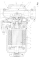
- FIG. 1 shows a centrifugal pump unit with a shaft sealing arrangement 1.
- the centrifugal pump unit shown in the embodiment is used to pump Wastewater is used in waste management and industry, in particular untreated wastewater with long-fiber or solid admixtures, liquids containing air and gas, as well as raw, activated and digested sludge.
- the medium enters the centrifugal pump, which is designed as a free-flow pump, through a suction port 2. Between a suction-side housing wall 3 and an impeller 4 there is a space 5 that also allows solids to pass through.
- the ball passage is a measure of the maximum diameter that solid particles can have in order to pass through the pump without clogging.
- the impeller 4 is designed as a free-flow impeller.
- the medium leaves the pump through a pressure port 6.
- the chamber 5 filled with medium is delimited by a pump housing 7 and a housing cover 8.
- the impeller 4 is connected in a rotationally fixed manner to a shaft 9, which drives the impeller 4 by means of a motor arrangement 10.
- the motor arrangement 10 comprises a rotor 11, a stator 12 and a motor housing 13.
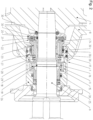
- Figure 2 shows an arrangement 1 for the shaft seal, which is positioned in an opening of the housing cover 8.
- the arrangement 1 comprises a first pairing 14 with a first stationary element 15, which is designed as an axially movable sliding ring.
- the arrangement 1 has a first rotating element 16 corresponding to the stationary element 15, which is formed integrally with a shaft sleeve 17.
- the shaft sleeve 17 is angled in an L-shape and forms a flange-like projection, so that a sealing surface is created which forms a sealing gap 18 running perpendicular to the shaft axis.
- the shaft sleeve 17 is connected to the shaft 9 in a rotationally fixed manner and forms the first rotating element 16 of the first mechanical seal, designed as a counter ring.
- the shaft sleeve 17 has an annular recess at its motor-side end, into which a ring-like element 19 designed as a flat wire locking ring engages and thereby secures the shaft sleeve 17 against axial displacement.
- the ring-like element 19 is arranged in a groove of the shaft 9.
- the shaft sleeve 17 is secured against axial displacement by a rotating support element 20.
- the rotating support element 20 forms a support for a further rotating element 21, which forms the counter ring of a further pairing 22.
- the further pairing 22 also comprises a further stationary element 23, which is designed as an axially displaceable sliding ring.
- the further mechanical seal has a sealing gap 24 for the formation of a lubricating film.
- a first spring element 25 acts on the stationary element 15 of the first pairing 14. This exerts a force in the axial direction.
- the spring element 25 is supported on a housing part 26 on the motor side.
- the housing part 26 is connected to a stationary carrier 27 via an adhesive connection 28.
- a further pairing 22 comprises a further spring element 29, which exerts an axial force on the stationary element 23 of the pump-side mechanical seal.
- the pump-side pairing 22 and the motor-side pairing 14 form a compact double seal module.
- the arrangement 1 forms a compact unit which can be positioned as a sealing cartridge in the opening of the housing cover 8 and is sealed with O-rings 30.
- the double seal module is designed in a tandem arrangement.
Landscapes
- Engineering & Computer Science (AREA)
- General Engineering & Computer Science (AREA)
- Mechanical Engineering (AREA)
- Mechanical Sealing (AREA)
- Structures Of Non-Positive Displacement Pumps (AREA)
Description
- Die Erfindung betrifft eine Anordnung zur Wellendichtung mit einer Paarung, die ein rotierendes Element und ein stationäres Element aufweist, die einen Dichtspalt für einen Schmierfilm ausbilden sowie eine Kreiselpumpeneinheit mit einer solchen Anordnung.
- Solche Wellendichtungen kommen beispielsweise bei Kreiselpumpen zum Einsatz, an der Durchführung der rotierenden Welle aus dem Pumpengehäuse.
- Gleitringdichtungen weisen einen Dichtspalt auf, der in der Regel rechtwinklig zur Wellenachse steht. Wellendichtungen dieser Bauart werden auch als axiale oder hydrodynamische Gleitringdichtungen (GLRD) bezeichnet. Solche Gleitringdichtungen (GLRD) benötigen gegenüber anderen Dichtungssystemen einen kleineren Raum und weisen einen geringeren Wartungsaufwand auf. Sie bewähren sich sowohl bei niedrigen als auch bei hohen abzudichtenden Drücken bzw. Umfanggeschwindigkeiten.
- Im Betrieb gleiten Dichtflächen aufeinander, die durch hydraulische und/oder mechanische Kräfte aufeinander gedrückt werden. Zwischen diesen beiden feinst bearbeiteten Gleitflächen befindet sich ein Dichtspalt mit einem meist flüssigen Schmierfilm. Die geringe Leckage gelangt bei Gleitringdichtungen (GLRD) meist beim Austritt in die Atmosphäre.
- Die gattungsgemäße Anordnung zur Wellendichtung weist eine Wellenhülse auf. Wellenhülsen können die Welle vor Verschleiß schützen. Treten Verschleißerscheinungen auf, so muss nur die deutlich preiswertere Wellenhülse ausgetauscht werden und nicht die gesamte Welle.
- Auch kann die Wellenhülse aus einem höherwertigeren Werkstoff gefertigt sein, der beständiger gegen Verschleiß und Korrosion ist. Dies spart Kosten gegenüber einer Ausführung der gesamten Welle aus diesem Werkstoff.
- In der
DE 199 28 141 A1 wird eine Dichtungsanordnung beschrieben, bei der eine Welle durch ein Gehäuse einer Kreiselpumpe geführt wird. Die Anordnung umfasst eine Wellenhülse, auf der Gleitringdichtungen mit einem rotierenden Element und einem stationären Element positioniert sind, zwischen denen ein Dichtspalt für einen Schmierfilm angeordnet ist. - Die
DE 202 05 419 U1 beschreibt eine Gleitringdichtungsanordnung mit einer Paarung zusammenwirkender Elemente, von denen eines drehfest an einem stationären Bauteil und das andere zur gemeinsamen Drehung an einem rotierenden Bauteil montiert ist. Eine Paarung umfasst eine Wellenhülse zur gemeinsamen Drehung mit der Welle, auf der ein erstes Element angeordnet ist. Das erste Element wirkt zusammen mit einem zweiten Element, das drehfest am Gehäuse gehalten ist. - In der
DE 298 00 616 U1 wird eine Doppel-Gleitringdichtung beschrieben. Ein dynamischer Gleitring ist an einer auf einer Welle angeordneten Wellenhülse befestigt. - Die
WO 95/14 185 A1 - Die
US 2008/181546 A1 beschreibt eine axiale Gleitlageranordnung mit einem Druckring, der für eine gemeinsame Drehung mit einer rotierenden Komponente vorgesehen ist. Der Druckring hat eine radiale Dichtungsfläche an einer seiner Endflächen zum Zusammenwirken mit einer radialen Dichtungsfläche eines nicht rotierenden Dichtungsrings. - Die
EP 1 921 356 A1 zeigt eine Gleitringdichtung, die eine abzudichtende Welle umschließt, umfassend einen Gegenring, wobei die Welle einen Bestandteil der Gleitringdichtung bildet und einstückig ineinander übergehend und materialeinheitlich mit dem Gegenring ausgebildet ist. - Die
US2013/259679 A1 offenbart eine Dichtungsanordnung, die eine Barriere zwischen dem Innen- und Außenbereich eines Kompressors bildet. Die Dichtungsbaugruppe umfasst eine primäre Dichtungsstufe und eine sekundäre Dichtungsstufe. - In der
EP 0 959 277 A2 wird eine Dichtungsanordnung für eine Tauchmaschine gezeigt. Die Dichtungsanordnung ist als eine leicht austauschbare Einheit aus zwei Gleitringdichtungen mit einem Zwischenraum für eine Sperrflüssigkeit ausgebildet, in dem eine Pumpe zur Umwälzung der Flüssigkeit angeordnet ist. - Die
DE 199 28 141 A1 beschreibt eine Dichtungsanordnung, bei der ein Rotationsteil durch ein Bauteil hindurchgeführt ist und das Bauteil mindestens einen Dichtungsraum zur Aufnahme von einer oder mehreren Gleitringdichtungen aufweist. - Die
DE 202 05 419 U1 offenbart eine Gleitring-Dichtungsanordnung mit wenigstens einem Paar zusammenwirkender Gleitringe, von denen einer drehfest an einem stationären Bauteil und der andere zur gemeinsamen Drehung mit einem rotierenden Bauteil montiert ist. - Die
WO 2014/081901 A1 zeigt eine Vorrichtung gemäß dem Oberbegriff des Anspruchs 1, aufweisend ein berührungsloses Lager, wobei eine poröse Verengung und Stege so konfiguriert sind, dass sie sich nur um einen definierten Betrag verformen, der durch den Differenzdruck zwischen jeder Seite der porösen Verengung entsteht. - Herkömmliche Anordnungen zur Wellendichtung weisen nur eine unzureichende Abdichtung oder zu große Abmessungen auf. Dies ist insbesondere bei Wellen mit kleinen Durchmessern problematisch.
- Aufgabe der Erfindung ist es, eine Anordnung zur Wellendichtung anzugeben, die eine möglichst geringe Leckage und eine kompakte Bauweise auch bei Wellen mit kleineren Durchmessern aufweist. Die Anordnung soll sich, insbesondere beim Einsatz in Kreiselpumpen, durch eine hohe Zuverlässigkeit und eine lange Lebensdauer auszeichnen. Sie soll zudem eine einfache Montage gewährleisten sowie für Wartungsarbeiten gut zugänglich sein. Weiterhin soll sich die Anordnung durch möglichst geringe Herstellungskosten auszeichnen.
- Diese Aufgabe wird erfindungsgemäß durch eine Anordnung mit den Merkmalen des Anspruchs 1 und eine Kreiselpumpeneinheit mit den Merkmalen des Anspruchs 11 gelöst. Bevorzugte Varianten sind den Unteransprüchen, der Beschreibung und den Zeichnungen zu entnehmen.
- Erfindungsgemäß ist das rotierende Element einstückig mit der Wellenhülse der Anordnung ausgebildet. Die Wellenhülse bildet durch eine Abwinkelung den rotierenden Gegenring einer Gleitringdichtung. Dadurch wird ein Dichtspalt gebildet, der im Wesentlichen rechtwinklig zur Wellenachse steht.
- Die Anordnung weist ein Federelement zur Erzeugung einer Anpresskraft zwischen dem rotierenden Element und dem stationären Element der Paarung auf. In Kombination mit einem gefederten Gleitring, der axial verschieblich ausgeführt ist, wird dadurch eine kompakte Gleitring-Gegenring-Paarung geschaffen, die auch bei Wellen mit kleineren Durchmessern eine zuverlässige Abdichtung und gleichzeitig eine kompakte Bauweise gewährleistet.
- Die erfindungsgemäße Konstruktion nimmt gegenüber herkömmlichen stationären Gleitringdichtungen einen geringeren Platzbedarf in Anspruch bei einer vergleichsweise geringen Leckage. Ein weiterer Vorteil der Erfindung besteht darin, dass in der Regel der Einbauraum von Standardnormdichtungen, insbesondere nach DIN EN 12756, beibehalten werden kann.
- Bei Kreiselpumpeneinheiten weist der Gehäusedeckel eine Öffnung auf, in welche die Anordnung zur Wellendichtung platziert wird. Es muss lediglich der Gehäusedeckel für die erfindungsgemäße Integration der Anordnung angepasst werden.
- Bei Kreiselpumpeneinheiten bildet die Wellenhülse erfindungsgemäß eine Gleitfläche auf der Atmosphärenseite. Durch die Funktionsintegration von Wellenhülse und Gleitfläche wird eine platzsparende Bauweise auch für sehr enge Raumverhältnisse geschaffen.
- Bei einer günstigen Variante der Erfindung ist das Federelement stationär. Dazu ist das Federelement an einem stationären Bauteil angeordnet. Dieses Bauteil führt keine Rotationsbewegungen aus. Somit steht das Federelement still und verursacht keine Vibrationen. Durch die stationäre Anordnung werden Einflüsse der Wellendurchbiegung auf die Standzeit und Dichtwirkung der Gleitringdichtung minimiert.
- Bei einer bevorzugten Variante ist das Federelement zwischen dem stationären Element und einem Gehäuseteil angeordnet. Das Federelement stützt sich dabei an den Gehäuseteilen ab und wirkt eine axiale Kraft auf das als Gleitring ausgebildete stationäre Teil aus, so dass dieses gegen das als Gleitring ausgebildete rotierende Teil gepresst wird. Das Federelement ist dabei vorzugsweise an einem Gehäuse für die Dichtung angeordnet.
- Erfindungsgemäß ist die Wellenhülse von einem ringartigen Element gegen axiale Verschiebungen gesichert. Dazu eignet sich insbesondere ein Flachdraht-Sicherungsring, der in einer Nut der Welle montiert ist, wobei die Anordnung der Nut entsprechend Standardnormdichtungen beibehalten werden kann. Die Wellenhülse weist eine ringförmige Aussparung auf, in welche das ringartige Element eingreift. Die axiale Wand der Aussparung bildet einen Anschlag, so dass eine axiale Verschiebung verhindert wird.
- Erfindungsgemäß steht die Wellenhülse mit einem rotierenden Trägerelement in Verbindung. Dieses bildet einen Anschlag für die Wellenhülse, so dass axiale Verschiebungen verhindert werden.
- Erfindungsgemäß ist die Wellenhülse zwischen dem Trägerelement und dem ringartigen Element fixiert.
- Das stationäre Element wird erfindungsgemäß von einem Gehäuseteil zumindest teilweise umschlossen. Dieses Dichtungsgehäuse schützt den gefederten Gleitring und bildet einen Raum für das Fluid, welches den Dichtspalt zwischen dem Gleitring und dem von der Wellenhülse gebildeten Gegenring schmiert.
- Erfindungsgemäß weist die Anordnung einen stationären Träger auf, der mit einem stationären Gehäuseteil verbunden ist. Dabei kommt bevorzugt eine nicht lösbare Verbindung zur Anwendung, wobei sich insbesondere eine Klebeverbindung eignet. Im Unterschied zu herkömmlichen Konstruktionen erfolgt die Verbindung somit nicht über Schrauben oder ähnlichen Festigungsmitteln, sondern über Klebenähte.
- Der stationäre Träger dient erfindungsgemäß als Träger für einen weiteren Gleitring, der ein weiteres stationäres Teil bildet. Dieses steht mit einem weiteren rotierenden Teil in Verbindung, das vorzugsweise als weiterer Gegenring ausgebildet ist. Bei dieser Variante umfasst die Anordnung somit zwei Gleitring-Gegenring-Paarungen, wobei erfindungsgemäß bei mindestens einer Paarung ein rotierender Gegenring von einer Wellenhülse gebildet wird.
- Diese Ausbildung als Doppeldichtungsmodul eignet sich insbesondere für den Einsatz bei Abwasserpumpen. Die Kreiselpumpe wird mit zwei Gleitringdichtungen abgedichtet, die von einer Flüssigkeit geschmiert werden.
- Vorzugsweise sind die beiden Dichtungen in Tandem-Anordnung positioniert. Dabei ergibt sich geeigneter Weise folgender Aufbau: Erster rotierender Gegenring, erster stationärer Gleitring, zweiter rotierender Gegenring, zweiter stationärer Gleitring.
- Als günstig erweist es sich, wenn beide Federelemente, die auf die axial verschieblichen stationären Gleitringe wirken, in stationären Bauteilen angeordnet sind.
- Bei der erfindungsgemäßen Dichtungspatrone in Tandem-Anordnung ist die Dichtfunktion der motorseitigen Gleitringdichtung des Doppeldichtungsmoduls auch bei Versagen der pumpenseitigen Gleitringdichtung gegeben.
- Die Federelemente können in unterschiedlichen Bauweisen ausgeführt sein. So können beispielsweise Gruppenfedern als konzentrisch angeordnete Federpakete zum Einsatz kommen. Weiterhin ist der Einsatz von Metallfaltenbälgen oder Wellfedern als Federelemente denkbar. Auch kann ein aus einem Elastomer gefertigter Balg als Federelement zum Einsatz kommen.
- Bei dem Doppeldichtungsmodul steht das weitere stationäre Element mit einem stationären Träger in Verbindung. Alternativ oder ergänzend kann das weitere rotierende Element mit einem rotierenden Träger in Verbindung stehen.
- Weitere Merkmale und Vorteile der Erfindung ergeben sich aus der Beschreibung eines Ausführungsbeispiels anhand von Zeichnungen und aus den Zeichnungen selbst.
- Dabei zeigt
- Figur 1
- einen Schnitt durch eine Kreiselpumpeneinheit,
- Figur 2
- einen Schnitt durch eine Anordnung zur Wellendichtung.
-
Figur 1 zeigt eine Kreiselpumpeneinheit mit einer Anordnung 1 zur Wellendichtung. Die im Ausführungsbeispiel dargestellte Kreiselpumpeneinheit wird zum Fördern von Schmutzwässern in der Abfallwirtschaft und der Industrie eingesetzt, insbesondere von ungeklärten Abwässern mit langfaserigen oder festen Beimengungen, luft- und gashaltigen Flüssigkeiten sowie Roh-, Belebt- und Faulschlamm. - Durch einen Saugmund 2 tritt das Medium in die als Freistrompumpe ausgeführte Kreiselpumpe ein. Zwischen einer saugseitigen Gehäusewand 3 und einem Laufrad 4 ist ein Raum 5 angeordnet, der einen Durchgang auch für Feststoffe ermöglicht. Dabei bildet der Kugeldurchgang ein Maß für den maximalen Durchmesser den Feststoffteilchen haben dürfen, um verstopfungsfrei die Pumpe zu passieren.
- Das Laufrad 4 ist als Freistromrad ausgeführt. Durch einen Druckstutzen 6 verlässt das Medium die Pumpe. Der mit Medium gefüllte Raum 5 wird von einem Pumpengehäuse 7 und einem Gehäusedeckel 8 begrenzt.
- Das Laufrad 4 ist drehfest mit einer Welle 9 verbunden, welche das Laufrad 4 mittels einer Motoranordnung 10 antreibt. Die Motoranordnung 10 umfasst einen Rotor 11, einen Stator 12 und ein Motorgehäuse 13.
-
Figur 2 zeigt eine Anordnung 1 zur Wellendichtung, die in einer Öffnung des Gehäusedeckels 8 positioniert ist. - Die Anordnung 1 umfasst eine erste Paarung 14 mit einem ersten stationären Element 15, das als axial beweglicher Gleitring ausgeführt ist.
- Erfindungsgemäß weist die Anordnung 1 ein zu dem stationären Element 15 korrespondierendes erstes rotierendes Element 16 auf, das einstückig mit einer Wellenhülse 17 ausgebildet ist.
- Die Wellenhülse 17 ist L-förmig abgewinkelt und bildet einen flanschartigen Vorsprung, so dass eine Dichtfläche geschaffen wird, die einen senkrecht zur Wellenachse verlaufenden Dichtspalt 18 bildet.
- Die Wellenhülse 17 ist drehfest mit der Welle 9 verbunden und bildet das als Gegenring ausgeführte erste rotierende Element 16 der ersten Gleitringdichtung.
- Die Wellenhülse 17 weist eine ringförmige Aussparung an ihrem motorseitigen Ende auf, in welche ein als Flachdraht-Sicherungsring ausgeführtes ringartiges Element 19 eingreift und dadurch die Wellenhülse 17 gegen axiale Verschiebungen sichert.
- Das ringartige Element 19 ist in einer Nut der Welle 9 angeordnet.
- Pumpenseitig wird die Wellenhülse 17 von einem rotierenden Trägerelement 20 gegen axiale Verschiebungen gesichert. Das rotierende Trägerelement 20 bildet einen Träger für ein weiteres rotierendes Element 21, welches den Gegenring einer weiteren Paarung 22 bildet.
- Die weitere Paarung 22 umfasst zudem ein weiteres stationäres Element 23, das als axial verschieblicher Gleitring ausgeführt ist.
- Die weitere Gleitringdichtung weist einen Dichtspalt 24 zur Bildung eines Schmierfilms auf.
- Auf das stationäre Element 15 der ersten Paarung 14 wirkt ein erstes Federelement 25. Dies übt eine Kraft in axialer Richtung aus. Das Federelement 25 stützt sich motorseitig an einem Gehäuseteil 26 ab.
- Das Gehäuseteil 26 ist mit einem stationären Träger 27 über eine Klebeverbindung 28 verbunden.
- Eine weitere Paarung 22 umfasst ein weiteres Federelement 29, das eine axiale Kraft auf das stationäre Element 23 der pumpenseitigen Gleitringdichtung ausübt.
- Die pumpenseitige Paarung 22 und die motorseitige Paarung 14 bilden ein kompaktes Doppeldichtungsmodul.
- Die Anordnung 1 bildet eine kompakte Baueinheit, die als Dichtungspatrone in die Öffnung des Gehäusedeckels 8 positioniert werden kann und mit O-Ringen 30 abgedichtet wird.
- Das Doppeldichtungsmodul ist in Tandem-Anordnung ausgeführt.
Claims (10)
- Anordnung (1) die eine Dichtung um eine Welle bereitstellt und aufweisend eine erste Paarung (14), die ein erstes rotierendes Element (16) und ein erstes stationäres Element (15) aufweist, die einen Dichtspalt (18) für einen Schmierfilm ausbilden, wobei die Anordnung (1) eine Wellenhülse (17) aufweist, wobei die Anordnung (1) eine weitere Paarung (22) mit einem weiteren rotierenden Element (21) und einem weiteren stationären Element (23) aufweist, zwischen denen ein Dichtspalt (24) für einen Schmierfilm angeordnet ist, wobei das erste rotierende Element (16) einstückig mit der Wellenhülse (17) ausgebildet ist, wobei die Anordnung (1) einen stationären Träger (27) und ein stationäres Gehäuseteil (26) umfasst, die miteinander verbunden sind, wobei das weitere stationäre Element (23) mit dem stationären Träger (27) in Verbindung steht, wobei das stationäre Element (15) von dem Gehäuseteil (26) zumindest teilweise umschlossen wird und die Wellenhülse (17) von einem ringartigen Element (19) gegen axiale Verschiebung gesichert ist,wobei die Wellenhülse (17) mit einem rotierenden Trägerelement (20) in Verbindung steht, welches eine Begrenzung gegen axiale Verschiebungen bildet,dadurch gekennzeichnet, dass die Wellenhülse (17) zwischen dem rotierenden Trägerelement (20) und dem ringartigen Element (19) fixiert ist.
- Anordnung nach Anspruch 1, wobei die Anordnung (1) ein Federelement (25) zur Erzeugung einer Anpresskraft zwischen dem rotierenden Element (16) und dem stationären Element (15) der ersten Paarung (14) aufweist.
- Anordnung nach Anspruch 2, wobei das Federelement (25) stationär ist.
- Anordnung nach Anspruch 1, wobei die Anordnung (1) ein weiteres Federelement (29) zur Erzeugung einer Anpresskraft zwischen dem weiteren rotierenden Element (21) und dem stationären Element (23) der weiteren Paarung (22) aufweist.
- Anordnung nach Anspruch 1 oder 4, wobei die Paarungen (14, 22) in Tandem-Anordnung zueinander positioniert sind.
- Anordnung nach Anspruch 4 oder 5, wobei das weitere Federelement (29) stationär ist.
- Anordnung nach einem der Ansprüche 1 bis 6, wobei es sich bei dem ringartigen Element (19) um einen Flachdraht-Sicherungsring handelt.
- Anordnung nach einem der Ansprüche 2 bis 7, wobei das erste Federelement (25) zwischen dem stationären Element (15) und dem Gehäuseteil (26) angeordnet ist.
- Anordnung nach Anspruch 1-8, wobei das weitere rotierende Element (21) mit dem rotierenden Trägerelement (20) in Verbindung steht.
- Kreiselpumpeneinheit mit einem Gehäusedeckel (8), der eine Öffnung aufweist, in der eine Anordnung (1) nach einem der Ansprüche 1 bis 9 platziert ist.
Applications Claiming Priority (2)
| Application Number | Priority Date | Filing Date | Title |
|---|---|---|---|
| DE102015221255.6A DE102015221255A1 (de) | 2015-10-30 | 2015-10-30 | Anordnung zur Wellendichtung |
| PCT/EP2016/075504 WO2017072065A1 (de) | 2015-10-30 | 2016-10-24 | Anordnung zur wellendichtung |
Publications (3)
| Publication Number | Publication Date |
|---|---|
| EP3368801A1 EP3368801A1 (de) | 2018-09-05 |
| EP3368801C0 EP3368801C0 (de) | 2024-08-21 |
| EP3368801B1 true EP3368801B1 (de) | 2024-08-21 |
Family
ID=57190023
Family Applications (1)
| Application Number | Title | Priority Date | Filing Date |
|---|---|---|---|
| EP16785169.0A Active EP3368801B1 (de) | 2015-10-30 | 2016-10-24 | Anordnung zur wellendichtung |
Country Status (5)
| Country | Link |
|---|---|
| EP (1) | EP3368801B1 (de) |
| CN (2) | CN117989169A (de) |
| DE (1) | DE102015221255A1 (de) |
| HU (1) | HUE069163T2 (de) |
| WO (1) | WO2017072065A1 (de) |
Families Citing this family (2)
| Publication number | Priority date | Publication date | Assignee | Title |
|---|---|---|---|---|
| DE102020134056B4 (de) | 2020-12-17 | 2025-07-31 | Netzsch Pumpen & Systeme Gmbh | Drehkolbenpumpe |
| DE102024116807A1 (de) | 2024-06-14 | 2025-12-18 | KSB SE & Co. KGaA | Kreiselpumpenanordnung |
Citations (4)
| Publication number | Priority date | Publication date | Assignee | Title |
|---|---|---|---|---|
| EP0959277A2 (de) * | 1998-05-18 | 1999-11-24 | Itt Manufacturing Enterprises, Inc. | Dichtungsvorrichtung |
| DE19928141A1 (de) * | 1999-06-19 | 2000-12-21 | Ksb Ag | Dichtungsanordnung |
| DE20205419U1 (de) * | 2002-04-08 | 2002-06-27 | Burgmann Dichtungswerke GmbH & Co. KG, 82515 Wolfratshausen | Gleitring-Dichtungsanordnung |
| WO2014081901A1 (en) * | 2012-11-20 | 2014-05-30 | New Way Machine Components, Inc. | Air bearing for use as seal |
Family Cites Families (17)
| Publication number | Priority date | Publication date | Assignee | Title |
|---|---|---|---|---|
| CH122417A (de) * | 1926-07-10 | 1927-09-16 | Sulzer Ag | Stopfbüchse für umlaufende Wellen. |
| SE9202849L (sv) * | 1992-10-01 | 1993-11-22 | Atlas Copco Tools Ab | Oljetätning för en snabbroterande axel |
| ATA235093A (de) | 1993-11-19 | 1995-05-15 | Fruehwirth Erich | Gleitringdichtung |
| DE29800616U1 (de) | 1998-01-15 | 1998-03-05 | Depac Dichtungstechnik Gmbh, Bludenz | Sperrdruckdichtung |
| US7997802B2 (en) * | 2003-05-13 | 2011-08-16 | Carl Freudenberg Kg | Axial plain bearing assembly |
| CN2644724Y (zh) * | 2003-09-27 | 2004-09-29 | 上海连成(集团)有限公司 | 离心泵整体集装式机械密封 |
| CN200940574Y (zh) * | 2006-08-16 | 2007-08-29 | 季裕成 | 一种新型化工离心泵 |
| DE102006053165A1 (de) * | 2006-11-09 | 2008-05-15 | Carl Freudenberg Kg | Gleitringdichtung, Gleitringdichtungsanordnung und deren Verwendung |
| CN201232656Y (zh) * | 2008-06-10 | 2009-05-06 | 宁波精科机械密封件制造有限公司 | 一种离心泵机械密封装置 |
| CN201475033U (zh) * | 2009-08-05 | 2010-05-19 | 宁波精科机械密封件制造有限公司 | 不锈钢离心泵密封装置 |
| CN102384102A (zh) * | 2010-08-31 | 2012-03-21 | 杨燕 | 一种耐腐蚀离心泵的机械密封 |
| CN201925221U (zh) * | 2010-12-30 | 2011-08-10 | 上海阿波罗机械股份有限公司 | 一种用于离心泵上的机械密封装置 |
| CN102116308B (zh) * | 2011-04-13 | 2012-08-29 | 襄樊五二五泵业有限公司 | 一种泵用可调式机械密封结构 |
| US9140269B2 (en) * | 2012-03-29 | 2015-09-22 | Solar Turbines Incorporated | Dry gas seal assembly |
| CN204041521U (zh) * | 2014-07-24 | 2014-12-24 | 上海瑞邦机械集团有限公司 | 一种改进型整体集装式离心泵密封装置 |
| DE102014214929A1 (de) * | 2014-07-30 | 2016-02-04 | Ksb Aktiengesellschaft | Anordnung zur Wellendichtung |
| CN204253430U (zh) * | 2014-11-03 | 2015-04-08 | 苏州景美生物科技有限公司 | 一种机械密封结构 |
-
2015
- 2015-10-30 DE DE102015221255.6A patent/DE102015221255A1/de not_active Withdrawn
-
2016
- 2016-10-24 HU HUE16785169A patent/HUE069163T2/hu unknown
- 2016-10-24 EP EP16785169.0A patent/EP3368801B1/de active Active
- 2016-10-24 WO PCT/EP2016/075504 patent/WO2017072065A1/de not_active Ceased
- 2016-10-24 CN CN202410054180.5A patent/CN117989169A/zh active Pending
- 2016-10-24 CN CN201680063361.8A patent/CN108138969A/zh active Pending
Patent Citations (4)
| Publication number | Priority date | Publication date | Assignee | Title |
|---|---|---|---|---|
| EP0959277A2 (de) * | 1998-05-18 | 1999-11-24 | Itt Manufacturing Enterprises, Inc. | Dichtungsvorrichtung |
| DE19928141A1 (de) * | 1999-06-19 | 2000-12-21 | Ksb Ag | Dichtungsanordnung |
| DE20205419U1 (de) * | 2002-04-08 | 2002-06-27 | Burgmann Dichtungswerke GmbH & Co. KG, 82515 Wolfratshausen | Gleitring-Dichtungsanordnung |
| WO2014081901A1 (en) * | 2012-11-20 | 2014-05-30 | New Way Machine Components, Inc. | Air bearing for use as seal |
Also Published As
| Publication number | Publication date |
|---|---|
| EP3368801A1 (de) | 2018-09-05 |
| EP3368801C0 (de) | 2024-08-21 |
| CN108138969A (zh) | 2018-06-08 |
| WO2017072065A1 (de) | 2017-05-04 |
| CN117989169A (zh) | 2024-05-07 |
| HUE069163T2 (hu) | 2025-02-28 |
| DE102015221255A1 (de) | 2017-05-04 |
Similar Documents
| Publication | Publication Date | Title |
|---|---|---|
| EP2013519B1 (de) | Dichtanordnung | |
| EP3014149B1 (de) | Radialwellendichtung | |
| WO2012136496A1 (de) | Wellendichtungseinsatz | |
| DE60306883T2 (de) | Spielfreier Stützring für Elastomerdichtung und Flansch | |
| EP3175155B1 (de) | Anordnung zur wellendichtung | |
| EP3430271B1 (de) | Kreiselpumpe mit einer anordnung zur reduzierung einer rückströmung | |
| EP3368801B1 (de) | Anordnung zur wellendichtung | |
| EP3029332B1 (de) | Axial geteilte pumpe | |
| EP2201250B1 (de) | Pumpeneinsatz | |
| EP2148096A1 (de) | Kreiselpumpe | |
| EP2180974A1 (de) | Spindelmotor | |
| DE102012012443A1 (de) | Motorkreiselpumpe mit einer Gleitringdichtung | |
| DE102020133327B4 (de) | Pumpenanordnung | |
| DE10232443B4 (de) | Hochdruck-Dichtung für hohe Drehzahlen | |
| DE2849256C3 (de) | Gleitringdichtung | |
| DE102014118702B4 (de) | Kurbelwelle und Kurbelwellenanordnung | |
| DE4401567C1 (de) | Wellendichtung | |
| EP4045823B1 (de) | Wellenanordnung, getriebe mit einer wellenanordnung und extruder mit getriebe mit einer wellenanordnung, mit einer relativ zu einem flanschteil drehbar gelagerten welle | |
| DE102008019449A1 (de) | Lagerung für eine Schraubenspindelpumpe | |
| DE102016210173A1 (de) | Gleitringdichtungsanordnung sowie Bohrloch-Fördervorrichtung | |
| WO2015149776A1 (de) | Lageranordnung | |
| EP3966473A1 (de) | Getriebe mit einem gehäuseteil, einer welle, einem ersten deckelteil und einem zweiten deckelteil | |
| DE102018009849B4 (de) | Nassläuferpumpe | |
| DE102011009386B4 (de) | Verdrängermaschine mit einem Verdrängergehäuse und einem spiralförmigen Verdrängerelement | |
| DE102020215571A1 (de) | Pumpenvorrichtung für ein hydraulisches System eines Kraftfahrzeugs, hydraulisches System |
Legal Events
| Date | Code | Title | Description |
|---|---|---|---|
| STAA | Information on the status of an ep patent application or granted ep patent |
Free format text: STATUS: UNKNOWN |
|
| STAA | Information on the status of an ep patent application or granted ep patent |
Free format text: STATUS: THE INTERNATIONAL PUBLICATION HAS BEEN MADE |
|
| PUAI | Public reference made under article 153(3) epc to a published international application that has entered the european phase |
Free format text: ORIGINAL CODE: 0009012 |
|
| STAA | Information on the status of an ep patent application or granted ep patent |
Free format text: STATUS: REQUEST FOR EXAMINATION WAS MADE |
|
| 17P | Request for examination filed |
Effective date: 20180313 |
|
| AK | Designated contracting states |
Kind code of ref document: A1 Designated state(s): AL AT BE BG CH CY CZ DE DK EE ES FI FR GB GR HR HU IE IS IT LI LT LU LV MC MK MT NL NO PL PT RO RS SE SI SK SM TR |
|
| AX | Request for extension of the european patent |
Extension state: BA ME |
|
| DAV | Request for validation of the european patent (deleted) | ||
| DAX | Request for extension of the european patent (deleted) | ||
| STAA | Information on the status of an ep patent application or granted ep patent |
Free format text: STATUS: EXAMINATION IS IN PROGRESS |
|
| 17Q | First examination report despatched |
Effective date: 20191129 |
|
| REG | Reference to a national code |
Ref country code: DE Ref legal event code: R079 Free format text: PREVIOUS MAIN CLASS: F16J0015340000 Ipc: F04D0029100000 Ref country code: DE Ref legal event code: R079 Ref document number: 502016016685 Country of ref document: DE Free format text: PREVIOUS MAIN CLASS: F16J0015340000 Ipc: F04D0029100000 |
|
| GRAP | Despatch of communication of intention to grant a patent |
Free format text: ORIGINAL CODE: EPIDOSNIGR1 |
|
| STAA | Information on the status of an ep patent application or granted ep patent |
Free format text: STATUS: GRANT OF PATENT IS INTENDED |
|
| RIC1 | Information provided on ipc code assigned before grant |
Ipc: F04D 29/10 20060101AFI20240315BHEP |
|
| INTG | Intention to grant announced |
Effective date: 20240408 |
|
| GRAS | Grant fee paid |
Free format text: ORIGINAL CODE: EPIDOSNIGR3 |
|
| GRAA | (expected) grant |
Free format text: ORIGINAL CODE: 0009210 |
|
| STAA | Information on the status of an ep patent application or granted ep patent |
Free format text: STATUS: THE PATENT HAS BEEN GRANTED |
|
| AK | Designated contracting states |
Kind code of ref document: B1 Designated state(s): AL AT BE BG CH CY CZ DE DK EE ES FI FR GB GR HR HU IE IS IT LI LT LU LV MC MK MT NL NO PL PT RO RS SE SI SK SM TR |
|
| REG | Reference to a national code |
Ref country code: GB Ref legal event code: FG4D Free format text: NOT ENGLISH |
|
| REG | Reference to a national code |
Ref country code: CH Ref legal event code: EP |
|
| REG | Reference to a national code |
Ref country code: DE Ref legal event code: R096 Ref document number: 502016016685 Country of ref document: DE |
|
| REG | Reference to a national code |
Ref country code: IE Ref legal event code: FG4D Free format text: LANGUAGE OF EP DOCUMENT: GERMAN |
|
| U01 | Request for unitary effect filed |
Effective date: 20240919 |
|
| U07 | Unitary effect registered |
Designated state(s): AT BE BG DE DK EE FI FR IT LT LU LV MT NL PT RO SE SI Effective date: 20241010 |
|
| U20 | Renewal fee for the european patent with unitary effect paid |
Year of fee payment: 9 Effective date: 20241018 |
|
| PG25 | Lapsed in a contracting state [announced via postgrant information from national office to epo] |
Ref country code: NO Free format text: LAPSE BECAUSE OF FAILURE TO SUBMIT A TRANSLATION OF THE DESCRIPTION OR TO PAY THE FEE WITHIN THE PRESCRIBED TIME-LIMIT Effective date: 20241121 |
|
| PG25 | Lapsed in a contracting state [announced via postgrant information from national office to epo] |
Ref country code: GR Free format text: LAPSE BECAUSE OF FAILURE TO SUBMIT A TRANSLATION OF THE DESCRIPTION OR TO PAY THE FEE WITHIN THE PRESCRIBED TIME-LIMIT Effective date: 20241122 Ref country code: PL Free format text: LAPSE BECAUSE OF FAILURE TO SUBMIT A TRANSLATION OF THE DESCRIPTION OR TO PAY THE FEE WITHIN THE PRESCRIBED TIME-LIMIT Effective date: 20240821 |
|
| PG25 | Lapsed in a contracting state [announced via postgrant information from national office to epo] |
Ref country code: IS Free format text: LAPSE BECAUSE OF FAILURE TO SUBMIT A TRANSLATION OF THE DESCRIPTION OR TO PAY THE FEE WITHIN THE PRESCRIBED TIME-LIMIT Effective date: 20241221 |
|
| PG25 | Lapsed in a contracting state [announced via postgrant information from national office to epo] |
Ref country code: HR Free format text: LAPSE BECAUSE OF FAILURE TO SUBMIT A TRANSLATION OF THE DESCRIPTION OR TO PAY THE FEE WITHIN THE PRESCRIBED TIME-LIMIT Effective date: 20240821 |
|
| PG25 | Lapsed in a contracting state [announced via postgrant information from national office to epo] |
Ref country code: ES Free format text: LAPSE BECAUSE OF FAILURE TO SUBMIT A TRANSLATION OF THE DESCRIPTION OR TO PAY THE FEE WITHIN THE PRESCRIBED TIME-LIMIT Effective date: 20240821 Ref country code: RS Free format text: LAPSE BECAUSE OF FAILURE TO SUBMIT A TRANSLATION OF THE DESCRIPTION OR TO PAY THE FEE WITHIN THE PRESCRIBED TIME-LIMIT Effective date: 20241121 |
|
| PG25 | Lapsed in a contracting state [announced via postgrant information from national office to epo] |
Ref country code: RS Free format text: LAPSE BECAUSE OF FAILURE TO SUBMIT A TRANSLATION OF THE DESCRIPTION OR TO PAY THE FEE WITHIN THE PRESCRIBED TIME-LIMIT Effective date: 20241121 Ref country code: PL Free format text: LAPSE BECAUSE OF FAILURE TO SUBMIT A TRANSLATION OF THE DESCRIPTION OR TO PAY THE FEE WITHIN THE PRESCRIBED TIME-LIMIT Effective date: 20240821 Ref country code: NO Free format text: LAPSE BECAUSE OF FAILURE TO SUBMIT A TRANSLATION OF THE DESCRIPTION OR TO PAY THE FEE WITHIN THE PRESCRIBED TIME-LIMIT Effective date: 20241121 Ref country code: IS Free format text: LAPSE BECAUSE OF FAILURE TO SUBMIT A TRANSLATION OF THE DESCRIPTION OR TO PAY THE FEE WITHIN THE PRESCRIBED TIME-LIMIT Effective date: 20241221 Ref country code: HR Free format text: LAPSE BECAUSE OF FAILURE TO SUBMIT A TRANSLATION OF THE DESCRIPTION OR TO PAY THE FEE WITHIN THE PRESCRIBED TIME-LIMIT Effective date: 20240821 Ref country code: GR Free format text: LAPSE BECAUSE OF FAILURE TO SUBMIT A TRANSLATION OF THE DESCRIPTION OR TO PAY THE FEE WITHIN THE PRESCRIBED TIME-LIMIT Effective date: 20241122 Ref country code: ES Free format text: LAPSE BECAUSE OF FAILURE TO SUBMIT A TRANSLATION OF THE DESCRIPTION OR TO PAY THE FEE WITHIN THE PRESCRIBED TIME-LIMIT Effective date: 20240821 |
|
| REG | Reference to a national code |
Ref country code: HU Ref legal event code: AG4A Ref document number: E069163 Country of ref document: HU |
|
| PG25 | Lapsed in a contracting state [announced via postgrant information from national office to epo] |
Ref country code: SM Free format text: LAPSE BECAUSE OF FAILURE TO SUBMIT A TRANSLATION OF THE DESCRIPTION OR TO PAY THE FEE WITHIN THE PRESCRIBED TIME-LIMIT Effective date: 20240821 |
|
| PG25 | Lapsed in a contracting state [announced via postgrant information from national office to epo] |
Ref country code: CZ Free format text: LAPSE BECAUSE OF FAILURE TO SUBMIT A TRANSLATION OF THE DESCRIPTION OR TO PAY THE FEE WITHIN THE PRESCRIBED TIME-LIMIT Effective date: 20240821 |
|
| PG25 | Lapsed in a contracting state [announced via postgrant information from national office to epo] |
Ref country code: SK Free format text: LAPSE BECAUSE OF FAILURE TO SUBMIT A TRANSLATION OF THE DESCRIPTION OR TO PAY THE FEE WITHIN THE PRESCRIBED TIME-LIMIT Effective date: 20240821 |
|
| REG | Reference to a national code |
Ref country code: CH Ref legal event code: PL |
|
| PLBE | No opposition filed within time limit |
Free format text: ORIGINAL CODE: 0009261 |
|
| STAA | Information on the status of an ep patent application or granted ep patent |
Free format text: STATUS: NO OPPOSITION FILED WITHIN TIME LIMIT |
|
| PG25 | Lapsed in a contracting state [announced via postgrant information from national office to epo] |
Ref country code: MC Free format text: LAPSE BECAUSE OF FAILURE TO SUBMIT A TRANSLATION OF THE DESCRIPTION OR TO PAY THE FEE WITHIN THE PRESCRIBED TIME-LIMIT Effective date: 20240821 |
|
| PG25 | Lapsed in a contracting state [announced via postgrant information from national office to epo] |
Ref country code: CH Free format text: LAPSE BECAUSE OF NON-PAYMENT OF DUE FEES Effective date: 20241031 |
|
| 26N | No opposition filed |
Effective date: 20250522 |
|
| PG25 | Lapsed in a contracting state [announced via postgrant information from national office to epo] |
Ref country code: IE Free format text: LAPSE BECAUSE OF NON-PAYMENT OF DUE FEES Effective date: 20241024 |
|
| PGFP | Annual fee paid to national office [announced via postgrant information from national office to epo] |
Ref country code: HU Payment date: 20251007 Year of fee payment: 10 |
|
| U20 | Renewal fee for the european patent with unitary effect paid |
Year of fee payment: 10 Effective date: 20251024 |
|
| PGFP | Annual fee paid to national office [announced via postgrant information from national office to epo] |
Ref country code: GB Payment date: 20251024 Year of fee payment: 10 |
|
| PG25 | Lapsed in a contracting state [announced via postgrant information from national office to epo] |
Ref country code: CY Free format text: LAPSE BECAUSE OF FAILURE TO SUBMIT A TRANSLATION OF THE DESCRIPTION OR TO PAY THE FEE WITHIN THE PRESCRIBED TIME-LIMIT; INVALID AB INITIO Effective date: 20161024 |