EP3368468B1 - Device for filling containers with a filling product - Google Patents
Device for filling containers with a filling product Download PDFInfo
- Publication number
- EP3368468B1 EP3368468B1 EP16788136.6A EP16788136A EP3368468B1 EP 3368468 B1 EP3368468 B1 EP 3368468B1 EP 16788136 A EP16788136 A EP 16788136A EP 3368468 B1 EP3368468 B1 EP 3368468B1
- Authority
- EP
- European Patent Office
- Prior art keywords
- distributor
- filling
- filling product
- shaft
- product
- Prior art date
- Legal status (The legal status is an assumption and is not a legal conclusion. Google has not performed a legal analysis and makes no representation as to the accuracy of the status listed.)
- Active
Links
- 239000012530 fluid Substances 0.000 claims description 2
- 239000000945 filler Substances 0.000 description 36
- 238000009826 distribution Methods 0.000 description 20
- 238000007789 sealing Methods 0.000 description 14
- 238000012546 transfer Methods 0.000 description 12
- 239000007789 gas Substances 0.000 description 9
- 238000013461 design Methods 0.000 description 5
- 235000013361 beverage Nutrition 0.000 description 3
- 238000004891 communication Methods 0.000 description 3
- 238000010276 construction Methods 0.000 description 3
- 238000005553 drilling Methods 0.000 description 3
- 238000012423 maintenance Methods 0.000 description 3
- 230000007704 transition Effects 0.000 description 3
- XLYOFNOQVPJJNP-UHFFFAOYSA-N water Substances O XLYOFNOQVPJJNP-UHFFFAOYSA-N 0.000 description 3
- QVGXLLKOCUKJST-UHFFFAOYSA-N atomic oxygen Chemical compound [O] QVGXLLKOCUKJST-UHFFFAOYSA-N 0.000 description 2
- 238000011161 development Methods 0.000 description 2
- 230000018109 developmental process Effects 0.000 description 2
- 238000011010 flushing procedure Methods 0.000 description 2
- 239000001301 oxygen Substances 0.000 description 2
- 229910052760 oxygen Inorganic materials 0.000 description 2
- 238000003860 storage Methods 0.000 description 2
- 238000004140 cleaning Methods 0.000 description 1
- 230000001419 dependent effect Effects 0.000 description 1
- 230000000694 effects Effects 0.000 description 1
- 238000005429 filling process Methods 0.000 description 1
- 239000004519 grease Substances 0.000 description 1
- 239000007788 liquid Substances 0.000 description 1
- 230000002906 microbiologic effect Effects 0.000 description 1
- 230000000630 rising effect Effects 0.000 description 1
- 238000000926 separation method Methods 0.000 description 1
Images


Classifications
-
- B—PERFORMING OPERATIONS; TRANSPORTING
- B67—OPENING, CLOSING OR CLEANING BOTTLES, JARS OR SIMILAR CONTAINERS; LIQUID HANDLING
- B67C—CLEANING, FILLING WITH LIQUIDS OR SEMILIQUIDS, OR EMPTYING, OF BOTTLES, JARS, CANS, CASKS, BARRELS, OR SIMILAR CONTAINERS, NOT OTHERWISE PROVIDED FOR; FUNNELS
- B67C3/00—Bottling liquids or semiliquids; Filling jars or cans with liquids or semiliquids using bottling or like apparatus; Filling casks or barrels with liquids or semiliquids
- B67C3/02—Bottling liquids or semiliquids; Filling jars or cans with liquids or semiliquids using bottling or like apparatus
- B67C3/22—Details
- B67C3/225—Means for filling simultaneously, e.g. in a rotary filling apparatus or multiple rows of containers
-
- B—PERFORMING OPERATIONS; TRANSPORTING
- B67—OPENING, CLOSING OR CLEANING BOTTLES, JARS OR SIMILAR CONTAINERS; LIQUID HANDLING
- B67C—CLEANING, FILLING WITH LIQUIDS OR SEMILIQUIDS, OR EMPTYING, OF BOTTLES, JARS, CANS, CASKS, BARRELS, OR SIMILAR CONTAINERS, NOT OTHERWISE PROVIDED FOR; FUNNELS
- B67C3/00—Bottling liquids or semiliquids; Filling jars or cans with liquids or semiliquids using bottling or like apparatus; Filling casks or barrels with liquids or semiliquids
- B67C3/02—Bottling liquids or semiliquids; Filling jars or cans with liquids or semiliquids using bottling or like apparatus
- B67C3/22—Details
-
- B—PERFORMING OPERATIONS; TRANSPORTING
- B67—OPENING, CLOSING OR CLEANING BOTTLES, JARS OR SIMILAR CONTAINERS; LIQUID HANDLING
- B67C—CLEANING, FILLING WITH LIQUIDS OR SEMILIQUIDS, OR EMPTYING, OF BOTTLES, JARS, CANS, CASKS, BARRELS, OR SIMILAR CONTAINERS, NOT OTHERWISE PROVIDED FOR; FUNNELS
- B67C3/00—Bottling liquids or semiliquids; Filling jars or cans with liquids or semiliquids using bottling or like apparatus; Filling casks or barrels with liquids or semiliquids
- B67C3/02—Bottling liquids or semiliquids; Filling jars or cans with liquids or semiliquids using bottling or like apparatus
- B67C3/06—Bottling liquids or semiliquids; Filling jars or cans with liquids or semiliquids using bottling or like apparatus using counterpressure, i.e. filling while the container is under pressure
-
- B—PERFORMING OPERATIONS; TRANSPORTING
- B67—OPENING, CLOSING OR CLEANING BOTTLES, JARS OR SIMILAR CONTAINERS; LIQUID HANDLING
- B67C—CLEANING, FILLING WITH LIQUIDS OR SEMILIQUIDS, OR EMPTYING, OF BOTTLES, JARS, CANS, CASKS, BARRELS, OR SIMILAR CONTAINERS, NOT OTHERWISE PROVIDED FOR; FUNNELS
- B67C3/00—Bottling liquids or semiliquids; Filling jars or cans with liquids or semiliquids using bottling or like apparatus; Filling casks or barrels with liquids or semiliquids
- B67C3/02—Bottling liquids or semiliquids; Filling jars or cans with liquids or semiliquids using bottling or like apparatus
- B67C3/22—Details
- B67C3/28—Flow-control devices, e.g. using valves
-
- B—PERFORMING OPERATIONS; TRANSPORTING
- B67—OPENING, CLOSING OR CLEANING BOTTLES, JARS OR SIMILAR CONTAINERS; LIQUID HANDLING
- B67C—CLEANING, FILLING WITH LIQUIDS OR SEMILIQUIDS, OR EMPTYING, OF BOTTLES, JARS, CANS, CASKS, BARRELS, OR SIMILAR CONTAINERS, NOT OTHERWISE PROVIDED FOR; FUNNELS
- B67C3/00—Bottling liquids or semiliquids; Filling jars or cans with liquids or semiliquids using bottling or like apparatus; Filling casks or barrels with liquids or semiliquids
- B67C3/02—Bottling liquids or semiliquids; Filling jars or cans with liquids or semiliquids using bottling or like apparatus
- B67C3/22—Details
- B67C2003/228—Aseptic features
Definitions
- the present invention relates to a device for filling a container with a filling product and in particular to a rotary filler for filling bottles or cans in a beverage bottling plant.
- a rotary distributor In order to transfer the filling product from a stationary part of the plant to the rotating part of the plant, i.e. the filler carousel, and also to transfer operating media, such as prestressing gas or pneumatic or hydraulic media to the filler carousel, it is known to provide a rotary distributor. It is known from the prior art to provide a stationary shaft on the stationary part of the plant, with the respective media and the filling product being introduced into the distributor shaft from below through bores or lines within this shaft. A distributor housing is provided on the rotating system part, ie the filler carousel, which is placed on the distributor shaft and which, together with the distributor shaft, forms ring channels.
- feed lines which feed the filling product to a filling product tank arranged underneath, for example a ring tank or a central tank, of the filling product carousel.
- the filling elements then obtain the filling product from this ring bowl or central bowl.
- the other media control media or pressurized gas for example, are transferred from below through the stationary distributor shaft to the distributor housing and then fed via corresponding supply lines to ring channels, from which the respective filling valves then remove the media.
- the distributor shaft is thus arranged in a stationary manner and the distributor housing with the supply lines to the respective ring tank or ring channel and the filling valves rotate accordingly relative to the stationary system parts and also relative to the distributor shaft.
- isolator housings In order to meet the respective hygiene requirements, devices for filling filling products into containers are regularly provided in isolator housings, in which an atmosphere that meets the respective hygiene requirements can be maintained. Depending on the filling product to be filled, either microbiological purity or low oxygen content can be the priority. Combined requirements of low oxygen content and an aseptic character of the atmosphere in the isolator housing can also be met in this way.
- the sealing between the rotating part, for example the filler carousel, and the stationary part of the system takes place, for example, via so-called water seals.
- a circumferential channel is provided on the stationary part, which can be filled with water.
- a revolving sword is provided on the rotating part, which is dimensioned in such a way that it dips into the water introduced into the channel.
- an exchange of gas with the environment can be prevented and an interior space that is essentially sealed off from the environment can be provided, so that a reliable rotary seal is achieved.
- the DE 10 2013 102 594 A1 describes a rotary media distributor for vessel filling machines, comprising, among other things, a stationary part of the system and a part of the system that rotates opposite this, on which at least one filling valve for filling a container to be filled with the filling product is arranged.
- the rotary distributor transfers a filling product from the stationary part of the plant to the rotating part of the plant. It has a distributor housing and a rotating distributor shaft accommodated in it with a bore for guiding the filling product.
- the JP 2000 255691A describes a rotary filling machine with a rotary media distributor.
- the DE 10 2012 109 884 A1 describes a device for filling at least one container with a filling product, which has a rotary media distributor.
- a device for filling containers with a filling product comprising a stationary part of the system and a part of the system that rotates relative to it, on which at least one filling valve for filling a container to be filled with the filling product is arranged. Also included is a rotary distributor for transferring the filling product and/or a medium from the stationary part of the system to the rotating part of the system, the rotary distributor having a distributor housing and a distributor shaft at least partially accommodated therein with at least one borehole for conducting the filling product and/or the medium.
- the distributor housing is arranged on the stationary part of the plant and the distributor shaft is arranged on the rotating part of the plant.
- the distributor housing is arranged on the stationary part of the plant and the distributor shaft is arranged on the rotating part of the plant, it can be achieved that the rotating part of the plant can be made more compact.
- this feature makes it possible to enable the filling product to be fed in exactly the same way as media to be fed in from above the filler carousel.
- the supply lines to the ring bowl which are known from the prior art and extend radially outwards from the rotating distributor housing, can be dispensed with. Accordingly, a more compact structure results below the proposed, stationary distributor housing.
- the filling product boiler can then also be arranged in a position which enables easier access for maintenance purposes.
- the filling product boiler for supplying and providing the filling product during the filling operation can thus also be provided in an advantageous position independently of the rotating system part, in particular also eccentrically to the axis of rotation of the filler carousel.
- the filling product lines for supplying the filling product to the filling valves, as well as the media lines Changed description pages to be attached to the lower end of the distributor shaft on notification under Rules 161(1) and 162 EPC , which also allows a more compact structure of the rotating part to be achieved than was the case in the conventional designs of filler carousels, in which a radial connection the supply lines to the filling valves or to the ring bowl were provided. Accordingly, the entire rotating part in the area of transfer or supply of the filling products and other media can be made more compact.
- the filling valves are each individually connected to filling valve feed lines on the lower end face of the distributor shaft facing the rotating part. At least one filling valve is connected to the lower end face of the distributor shaft via a filling product line, with the connection of the filling product line being oriented in the direction of the axis of rotation of the distributor shaft. Due to the connection to the lower end face, a compact configuration of the connection of the filling valves can be achieved since the respective lines can be routed in the direction of the axis of rotation.
- a distributor plate is arranged on the lower end face of the distributor shaft, in which at least one distribution chamber is defined, to which at least one filling product line, preferably also at least one media line, is connected.
- a connection for the filling product is provided in the end face of the distributor housing, which opens into a distribution chamber arranged between the upper end face of the distributor shaft and the distributor housing, which communicates with a bore in the distributor shaft.
- Each filling valve is preferably connected to the distributor shaft via a separate filling product line.
- the individual connection of each filling valve to the distributor shaft makes it possible to dispense with the provision of a ring bowl in the rotating part, so that the rotating part and the use of the filling valves can also be made more compact overall and have a lower mass. It is also possible, for example, to install a flow meter or other sensors in each of the individual feed lines, which enables individual control of the filling product feed to each filling valve, and an improved system control can be achieved as a result.
- the rotating mass and thus the moment of inertia of the entire rotating part is reduced, which means that the entire system structure can be designed more efficiently and, for example, the design of bearings and motors can be designed with smaller dimensions.
- a distributor plate is attached to the end face of the distributor shaft, via which the respective filling valves are connected to the distributor shaft. Accordingly, the distributor plate rotates together with the rotating distributor shaft. Distribution channels are particularly preferably provided in the distributor plate, via which the medium discharged from the distributor shaft, for example the filling product or filling product components, can be transferred to the respective delivery points, in particular the delivery points provided by means of the individual line connections.
- a central supply of medium through the distributor housing to the distributor shaft is particularly preferred, which is introduced essentially axially to the distributor shaft through the distributor housing into a receiving area defined between the distributor shaft and the distributor housing, and is then passed through a corresponding bore provided in the distributor shaft to the end face of the distributor shaft or a distribution chamber in the distributor plate provided on the end face of the distributor shaft.
- the bore that is passed through the distributor shaft is preferably executed laterally radially out of the distributor shaft in order to then be introduced into the distribution chamber on the end face.
- a filling product boiler is provided, which is arranged above the rotary distributor and eccentrically to this on the stationary part of the plant, and the filling product is fed to a connection in the distributor housing via filling product piping.
- At least one media line forms a fluid connection between a bore provided in the distributor shaft and a ring line provided in the rotating system part.
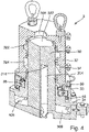
- a device 1 for filling containers can be seen schematically in a partially sectioned, perspective view.
- the device 1 comprises a filler carousel 10, on the circumference of which a plurality of filling valves 12 are held on a filling valve carrier 120, by means of which the filling of containers to be filled, not shown here, is carried out.
- the filler carousel 10 rotates relative to a stationary plant part 14 on which the filler carousel 10 is mounted.
- a torque support 140 is shown as part of the stationary system part 14, under which the filler carousel 10 rotates.
- the rotation of the filler carousel 10 in the filling operation causes the containers to be filled to be transported arranged under each filling valve 12, with the container interiors possibly being flushed with a flushing gas, the containers then being pressurized with a tensioning gas and then being filled with the filling product.
- the construction of a filling carousel 10 with filling valves 12 arranged thereon is known in principle.
- a rotary distributor 3 is provided to transfer the filling product and other media such as a first medium in the form of a flushing or clamping gas or a second medium in the form of control air from the stationary part of the system 14 to the rotating part of the system in the form of the filler carousel 10.
- the rotary distributor 3 has a distributor shaft 30 and a distributor housing 32 .
- the distributor housing 32 is firmly connected to the stationary part of the system 14 and does not rotate during the filling operation.
- the distributor shaft 30 is connected to the filler carousel 10, ie the rotating part of the system, and rotates accordingly during the filling operation together with the filler carousel 10.
- the rotary distributor 3 is also one of the Figures 2-4 described in detail.
- the filling valves 12 of the filler carousel 10 are connected to the rotary distributor 3 via filling product lines 2 in order to be able to feed the filling product to the respective filling valves 12 .
- a flow meter 20 is provided in each of the filling product lines 2, which lead from the rotary distributor 3 to the filling valves 12, by means of which the flow of the filling product from the rotary distributor 3 to the filling valve 12 can be measured and monitored accordingly.
- each filling valve 12 is connected to the rotary distributor 3 via a separate filling product line 2 and a flow meter 20 is arranged in each filling product line 2 . This enables the amount of filling product dispensed from each filling valve 12 to be precisely monitored and controlled.
- only selected filling product lines 2 are provided with a flow meter 20 and the filling product flows of the filling product lines 2 not provided with a flow meter 20 are approximately determined therefrom.
- media lines 22 and 24 are provided in order to transfer additional media to the filler carousel 10.
- a first medium for example the pressurized gas
- a second medium for example control air/compressed air
- the media lines 22, 24 each open into a ring line 220, 240.
- the ring lines 220, 240 are installed in the filling valve carrier 120 of the filler carousel 10 and have supply lines to the respective filling valves 12.
- the respective medium for example Clamping gas as the first medium or control air as the second medium
- the respective medium are transferred via the ring lines 220, 240 to the respective filling valves 12 or to their control via valve blocks 122 shown schematically, with the transfer of the respective media to the filling valves 12 then by means of the ring lines 220, 240 takes place.
- the rotary distributor 3 comprises a distributor housing 32 which is firmly connected to the stationary plant part 14 and a distributor shaft 30 which is firmly connected to the rotating plant part, ie the filler carousel 10 . Accordingly, during operation, the distributor shaft 30 rotates together with the filler carousel 10 in the distributor housing 32.
- a distributor plate 4 is provided on the distributor shaft 30, to which the filling product lines 2 and media lines 22, 24 described above are connected. The distributor plate 4 rotates together with the distributor shaft 30.
- the distributor shaft 30 is mounted on the distributor housing 32 by means of a bearing 38 which is supported on a sealing element 34 of the distributor shaft 30 and on a bearing ring 33 of the distributor housing 32 .
- the sealing element 34 is pressed onto the distributor shaft 30 in a ring shape and is connected to it in a material-locking manner.
- the bearing ring 33 is fastened to the distributor housing 32 via bolts.
- the transition from the stationary part to the rotating part runs through the bearing 38, with the transition to the bearing ring 33 being formed on the stationary side and the transition to the sealing element 34 being formed on the rotating side.
- a shaft sealing ring 36 is held on the sealing element 34 and seals the sealing element 34 with respect to the distributor housing 32 .
- Another shaft sealing ring 46 is held on the bearing ring 33 and seals the bearing ring 33 against the sealing element 34 . Between the two shaft sealing rings 36, 46 there is a sealed storage space which prevents grease from getting into the environment from the bearing 38 or cleaning media from attacking the bearing 38.
- the distributor housing 32 Between the distributor housing 32 and the components rotating together with the distributor shaft 30 there is a parting plane at reference number 44. At this parting plane, the distributor housing 32 can be pulled upwards for maintenance purposes, for example to replace the shaft seal 36.
- Another separating plane results at reference number 48.
- the distributor housing 32 together with the distributor shaft 30 and the sealing element 34 can also be lifted off for maintenance purposes, for example for replacing bearings or replacing seals.
- Bores 302 , 304 , 306 extending essentially in the direction of the axis of rotation 100 of the distributor shaft 30 are provided in the distributor shaft 30 .
- the bores 302 and 304 are used to transfer the media mentioned above, ie in particular the first medium and the second medium, to the filler carousel 10 .
- the bore 306 is intended to transfer the filling product to the filling carousel 10 .
- the bore 306 is provided in the distributor shaft 30 in such a way that it extends downwards, starting from the upper end face 330 of the distributor shaft 30, and is then led out again radially to the side via a lateral outlet bore 307 from the distributor shaft 30.
- the filling product which is conducted through the bore 306, enters the distributor housing 32 from the upper end face of the distributor housing 32 through a connection 326 for the filling product and flows into a distribution space 327 formed between the upper end face 330 of the distributor shaft 30 and the distributor housing 32 a.
- the filling product flows from this distribution space 327 via the bore 306 and the outlet bore 307 into a distribution chamber 308.
- the distribution space 327 is designed geometrically in such a way that rising air bubbles cannot be trapped but can be discharged through the connection 326 . Accordingly, there are no undercuts behind which air bubbles could get trapped, and the upper part of the valve chamber is constructed so that it rises slightly towards connection 326 in such a way that air can escape accordingly.
- each medium there is only one bore in the distributor shaft 30 for each medium.
- the distributor housing 32 there is preferably only one connection hole for each medium and accordingly only one medium piping, which again reduces the effort for the connection and the commissioning of a device according to the invention.
- the distribution chamber 308 is formed between the distributor plate 4 , which is arranged on the lower end face 332 of the distributor shaft 30 , and a sealing element 40 of the distributor shaft 32 .
- the distributor plate 4 In the distributor plate 4 there are holes 408 introduced, to which a connection of a filling product line 2 is possible.
- the bores 408 in the distributor plate 4 are formed in the direction of the axis of rotation 100 of the filler carousel 10 .
- the bores 408 for connecting the individual filling product lines 2 are provided on the largest radius of all connections.
- the connections for the filling product lines are thus located radially on the outside and the connections for the media lines 22, 24 on the inside. In this way, a compact structure can be achieved, which at the same time allows each filling valve 12 to be connected individually via its own filling product line 2 .
- the design of the distribution chamber 308 accordingly enables all filling valves 12 to be connected via individual filling product lines 2 by connecting them to the respective bores 408 in the distributor plate 4.
- the respective connection of the filling product lines 2, as in figure 1 at this time, takes place in a direction which is parallel to the axis direction of the transfer shaft 30 .
- the media which are guided, for example, through the bore 304 in the distributor shaft 3, come out, for example figure 3 as can be seen, on the lower end face 332 of the distributor shaft, into a distribution chamber 305 arranged in the distributor plate 4 .
- An axial bore 405 in the distributor plate 4 enables the media, and in particular the first medium, to be fed to the filling valves 12 or to the ring line 220 by means of the media line 22 .
- An annular channel 324 is formed between the distributor housing 32 and the distributor shaft 30 , which is formed in the inner circumference of the distributor housing 32 and is sealed at the top and bottom by seals 5 arranged above and below the annular channel 324 .
- the annular channel 324 is in communication with the bore 304 via a radial opening 314 in the distributor shaft 3 .
- the ring channel 324 is preferably designed in such a way that air can be easily discharged in the upper part of the ring channel and no liquids can remain in the lower part.
- the corresponding medium can then be introduced into the ring channel 324 from the outside via a connection 325 in the distributor housing 32 .
- the medium introduced via connection 325 enters annular channel 324, then via radial opening 314 into bore 304, via which it is then introduced into distribution chamber 305, and then via bore 405 in the media line 22 to be introduced.
- the media line 22 then supplies the medium to the ring line 220 on the filler carousel 10.
- annular channel 322 is formed in the inner circumference of the distributor housing 32, is formed between the distributor housing 32 and the distributor shaft 30 and is sealed off at the top and bottom by means of seals 5.
- the annular channel 322 is connected to the bore 302 via a radial opening 312 in the distributor shaft 30 .
- the bore 302 opens out via the lower end face 332 of the distributor shaft 30 into a distribution chamber 303 which is connected to the media line 24 via a bore 403 .
- the media line 24 is connected to the ring line 240 and can then provide the individual filling valves 12 with the second medium.
- the distributor housing 32 is arranged in the rotary distributor 3 in a stationary and non-rotatable manner with the stationary system part 14 of the device 1 and the distributor shaft 30 rotates together with the distributor plate 4 and the sealing element 34 together with the filler carousel 10 .
- the respective filling product lines 2 are connected to the rotary distributor 3 by connecting the filling product lines 2 to the distributor plate 4 in the direction of the axis of rotation 100 of the distributor shaft 30 and then feeding them individually to the individual filling valves 12 .
- the supply of further media for example pneumatic air or pressurized gas, is also achieved by connecting the respective media lines 22, 24 to the distributor plate 4, this connection also being achieved in the direction of the axis of rotation 100 of the distributor shaft 30.
- the top part of the filler which in the exemplary embodiments shown is formed, for example, by the standing system part 14 embodied as a platform, is preferably height-adjustable.
- the swivel joint connections required for the height adjustment are partially integrated into the vertical distributor housing 32.
- the filling product is made available via a filling product tank 6, which can be positioned as desired, but is preferably arranged above the rotary distributor 3 and to the side of it.
- the filling product boiler 6 can then be connected to the connection 326 on the distributor housing 32 via a corresponding filling product piping 60 .
- the filling product is accordingly of the Filling product boiler 6 fed to the rotary distributor 3 from above via the filling product piping 60 .
- Media piping 62 can also be fed to the rotary distributor 3 and then opens out radially into the distributor housing 32 at the position at which the connection 325 is provided.
- a position for the filling product boiler 6 does not have to be specified and it can be arranged in any position that is advantageous for the respective structure.
- the filler carousel 10 does not include the filling product boiler 6, so that the filler carousel 10 has a reduced mass overall and therefore also a reduced moment of inertia. In this way, the drives and the mounting of the filler carousel 10 can be configured in a correspondingly simpler manner compared to the conventional ones.
Description
Die vorliegende Erfindung betrifft eine Vorrichtung zum Befüllen eines Behälters mit einem Füllprodukt und insbesondere einen Rundläuferfüller zum Befüllen von Flaschen oder Dosen in einer Getränkeabfüllanlage.The present invention relates to a device for filling a container with a filling product and in particular to a rotary filler for filling bottles or cans in a beverage bottling plant.
Aus dem Stand der Technik ist es bekannt, Flaschen und Dosen in Getränkeabfüllanlagen mittels Rundläuferfüllern zu befüllen, bei welchen eine Mehrzahl von Füllorganen auf dem Umfang eines Füllerkarussells angeordnet sind, welche zum Einbringen des Füllprodukts in den jeweils zu befüllenden Behälter vorgesehen sind. Die zu befüllenden Behälter werden während des Befüllvorganges unterhalb des jeweiligen Füllorgans gehalten und laufen entsprechend zusammen mit den Füllorganen an dem Füllerkarussell um.It is known from the prior art to fill bottles and cans in beverage bottling plants using rotary fillers in which a plurality of filling elements are arranged on the circumference of a filler carousel, which are provided for introducing the filling product into the respective container to be filled. During the filling process, the containers to be filled are held below the respective filling element and rotate accordingly together with the filling elements on the filler carousel.
Um das Füllprodukt von einem stationären Anlagenteil auf den rotierenden Anlagenteil, also das Füllerkarussell, zu übergeben und um auch Betriebsmedien, wie beispielsweise Vorspanngas oder Pneumatik- beziehungsweise Hydraulikmedien auf das Füllerkarussell zu übertragen, ist es bekannt, einen Drehverteiler vorzusehen. Dabei ist aus dem Stand der Technik bekannt, eine stationäre Welle an dem stehenden Anlagenteil vorzusehen, wobei durch Bohrungen beziehungsweise Leitungen innerhalb dieser Welle die jeweiligen Medien sowie das Füllprodukt von unten in die Verteilerwelle eingebracht werden. An dem rotierenden Anlagenteil, also dem Füllerkarussell, ist ein Verteilergehäuse vorgesehen, welches auf der Verteilerwelle aufgesetzt ist und welches zusammen mit der Verteilerwelle Ringkanäle ausbildet. An den Ringkanälen des Verteilergehäuses radial nach außen zeigend angeschlossen sind Zuführleitungen, welche das Füllprodukt einem darunter angeordneten Füllproduktkessel, beispielsweise einem Ringkessel oder einem Zentralkessel, des Füllproduktkarussells zuleiten. Die Füllorgane beziehen dann aus diesem Ringkessel beziehungsweise Zentralkessel das Füllprodukt. Auch die weiteren Medien, beispielsweise Steuermedien oder Spanngas, werden von unten durch die stationäre Verteilerwelle auf das Verteilergehäuse übergeleitet und dann über entsprechende Zuleitungen Ringkanälen zugeleitet, aus welchen die jeweiligen Füllventile dann die Medien entnehmen. Damit ist die Verteilerwelle stationär angeordnet und das Verteilergehäuse mit den Zuleitungen zu dem jeweiligen Ringkessel oder Ringkanal sowie die Füllventile rotieren entsprechend relativ zu den stationären Anlagenteilen und auch relativ zu der Verteilerwelle.In order to transfer the filling product from a stationary part of the plant to the rotating part of the plant, i.e. the filler carousel, and also to transfer operating media, such as prestressing gas or pneumatic or hydraulic media to the filler carousel, it is known to provide a rotary distributor. It is known from the prior art to provide a stationary shaft on the stationary part of the plant, with the respective media and the filling product being introduced into the distributor shaft from below through bores or lines within this shaft. A distributor housing is provided on the rotating system part, ie the filler carousel, which is placed on the distributor shaft and which, together with the distributor shaft, forms ring channels. Connected to the ring channels of the distributor housing, pointing radially outwards, are feed lines which feed the filling product to a filling product tank arranged underneath, for example a ring tank or a central tank, of the filling product carousel. The filling elements then obtain the filling product from this ring bowl or central bowl. Also the other media control media or pressurized gas, for example, are transferred from below through the stationary distributor shaft to the distributor housing and then fed via corresponding supply lines to ring channels, from which the respective filling valves then remove the media. The distributor shaft is thus arranged in a stationary manner and the distributor housing with the supply lines to the respective ring tank or ring channel and the filling valves rotate accordingly relative to the stationary system parts and also relative to the distributor shaft.
Vorrichtungen zur Abfüllung von Füllprodukten in Behältern sind, um den jeweiligen Hygieneanforderungen gerecht zu werden, regelmäßig in Isolatorgehäusen vorgesehen, in welchen eine den jeweiligen Hygieneanforderungen gerecht werdende Atmosphäre aufrechterhalten werden kann. Je nach abzufüllendem Füllprodukt können dabei entweder mikrobiologische Reinheit oder Sauerstoffarmut im Vordergrund stehen. Auch kombinierte Anforderungen aus niedrigem Sauerstoffgehalt und einer aseptischen Ausprägung der Atmosphäre in dem Isolatorgehäuse können auf diese Weise erfüllt werden.In order to meet the respective hygiene requirements, devices for filling filling products into containers are regularly provided in isolator housings, in which an atmosphere that meets the respective hygiene requirements can be maintained. Depending on the filling product to be filled, either microbiological purity or low oxygen content can be the priority. Combined requirements of low oxygen content and an aseptic character of the atmosphere in the isolator housing can also be met in this way.
Die Abdichtung zwischen drehendem Teil, also beispielsweise dem Füllerkarussell, und stationärem Anlagenteil findet dabei beispielsweise über so genannte Wasserschlösser statt. Hierbei ist eine umlaufende Rinne am stationären Teil vorgesehen, welche mit Wasser befüllt werden kann. Am rotierenden Teil ist ein umlaufendes Schwert vorgesehen, welches so dimensioniert ist, dass es in das in der Rinne eingebrachte Wasser eintaucht. Entsprechend kann hierüber ein Austausch von Gas mit der Umgebung verhindert werden und ein im Wesentlichen gegenüber der Umgebung abgedichteter Innenraum bereitgestellt werden, so dass eine zuverlässige Drehdichtung erreicht wird.The sealing between the rotating part, for example the filler carousel, and the stationary part of the system takes place, for example, via so-called water seals. Here, a circumferential channel is provided on the stationary part, which can be filled with water. A revolving sword is provided on the rotating part, which is dimensioned in such a way that it dips into the water introduced into the channel. Correspondingly, an exchange of gas with the environment can be prevented and an interior space that is essentially sealed off from the environment can be provided, so that a reliable rotary seal is achieved.
Die
Ausgehend von dem bekannten Stand der Technik ist es eine Aufgabe der vorliegenden Erfindung, eine Vorrichtung zum Befüllen von Behältern mit einem Füllprodukt bereitzustellen, welche einen kompakteren Aufbau ermöglicht.Proceeding from the known state of the art, it is an object of the present invention to provide a device for filling containers with a filling product, which device enables a more compact construction.
Geänderte Beschreibungsseiten auf Mitteilung nach Regel 161(1) und 162 EPÜ Amended description pages on Rules 161(1) and 162 EPC communication
Diese Aufgabe wird durch eine Vorrichtung zum Befüllen von Behältern in einer Getränkeabfüllanlage mit den Merkmalen des Anspruchs 1 gelöst. Vorteilhafte Weiterbildungen ergeben sich aus den Unteransprüchen.This object is achieved by a device for filling containers in a beverage bottling plant with the features of
Entsprechend wird eine Vorrichtung zum Befüllen von Behältern mit einem Füllprodukt vorgeschlagen, umfassend einen stehenden Anlagenteil und einen gegenüber diesem rotierenden Anlagenteil, an welchem mindestens ein Füllventil zum Befüllen eines zu befüllenden Behälters mit dem Füllprodukt angeordnet ist. Weiterhin ist ein Drehverteiler zum Überführen des Füllprodukts und/oder eines Mediums von dem stehenden Anlagenteil auf den rotierenden Anlagenteil umfasst, wobei der Drehverteiler ein Verteilergehäuse und eine darin zumindest teilweise aufgenommene Verteilerwelle mit mindestens einer Bohrung zur Leitung des Füllprodukts und/oder des Mediums aufweist. Erfindungsgemäß ist das Verteilergehäuse an dem stehenden Anlagenteil angeordnet und die Verteilerwelle ist an dem rotierenden Anlagenteil angeordnet.Accordingly, a device for filling containers with a filling product is proposed, comprising a stationary part of the system and a part of the system that rotates relative to it, on which at least one filling valve for filling a container to be filled with the filling product is arranged. Also included is a rotary distributor for transferring the filling product and/or a medium from the stationary part of the system to the rotating part of the system, the rotary distributor having a distributor housing and a distributor shaft at least partially accommodated therein with at least one borehole for conducting the filling product and/or the medium. According to the invention, the distributor housing is arranged on the stationary part of the plant and the distributor shaft is arranged on the rotating part of the plant.
Dadurch, dass das Verteilergehäuse an dem stehenden Anlagenteil angeordnet ist und die Verteilerwelle an dem rotierenden Anlagenteil angeordnet ist, kann erreicht werden, dass der rotierende Anlagenteil kompakter ausgebildet werden kann. Insbesondere ist es über diese Ausprägung möglich, eine Füllproduktzufuhr genauso wie die Zufuhr von Medien von oberhalb des Füllerkarussells aus zu ermöglichen. Damit kann auf die aus dem Stand der Technik bekannten, sich radial von dem rotierenden Verteilergehäuse nach außen hin erstreckenden Zuleitungen zum Ringkessel verzichtet werden. Entsprechend ergibt sich unterhalb des vorgeschlagenen, stationären Verteilergehäuses ein kompakterer Aufbau. Insbesondere kann der Füllproduktkessel dann auch in einer Position angeordnet werden, welche einen einfacheren Zugang zu Wartungszwecken ermöglicht.Because the distributor housing is arranged on the stationary part of the plant and the distributor shaft is arranged on the rotating part of the plant, it can be achieved that the rotating part of the plant can be made more compact. In particular, this feature makes it possible to enable the filling product to be fed in exactly the same way as media to be fed in from above the filler carousel. This means that the supply lines to the ring bowl, which are known from the prior art and extend radially outwards from the rotating distributor housing, can be dispensed with. Accordingly, a more compact structure results below the proposed, stationary distributor housing. In particular, the filling product boiler can then also be arranged in a position which enables easier access for maintenance purposes.
Der Füllproduktkessel zur Zufuhr und zur Bereitstellung des Füllproduktes im Füllbetrieb kann damit auch unabhängig von dem rotierenden Anlagenteil in einer vorteilhaften Position, insbesondere auch exzentrisch zu der Rotationsachse des Füllerkarussells, bereitgestellt werden. Durch den Verzicht auf einen Ringkessel für das Füllprodukt an dem Füllerkarussell wird auch die rotierende Masse und damit auch das Trägheitsmoment reduziert, so dass die Lager für die Lagerung des Füllerkarussells und der Antrieb zum Antrieb des Füllerkarussells weniger stark ausgelegt werden müssen.The filling product boiler for supplying and providing the filling product during the filling operation can thus also be provided in an advantageous position independently of the rotating system part, in particular also eccentrically to the axis of rotation of the filler carousel. By doing without a ring bowl for the filling product on the filler carousel, the rotating mass and thus also the moment of inertia are reduced, so that the bearings for supporting the filler carousel and the drive for driving the filler carousel have to be designed to be less powerful.
Weiterhin ist es durch die Ausbildung der Verteilerwelle an dem rotierenden Anlagenteil möglich, die Füllproduktleitungen zur Zufuhr des Füllprodukts zu den Füllventilen, sowie die Medienleitungen Geänderte Beschreibungsseiten auf Mitteilung nach Regel 161(1) und 162 EPÜ an der unteren Stirnseite der Verteilerwelle anzubringen, wodurch ebenfalls ein kompakterer Aufbau des rotierenden Teils erreicht werden kann, als dies in den herkömmlichen Ausbildungen von Füllerkarussellen der Fall war, bei welchen eine radiale Anbindung der Zuleitungen zu den Füllventilen beziehungsweise zu dem Ringkessel vorgesehen war. Entsprechend kann der gesamte rotierende Teil im Bereich der Überführung beziehungsweise Zuleitung der Füllprodukte sowie anderer Medien kompakter ausgestaltet werden.Furthermore, it is possible due to the design of the distributor shaft on the rotating part of the system, the filling product lines for supplying the filling product to the filling valves, as well as the media lines Changed description pages to be attached to the lower end of the distributor shaft on notification under Rules 161(1) and 162 EPC , which also allows a more compact structure of the rotating part to be achieved than was the case in the conventional designs of filler carousels, in which a radial connection the supply lines to the filling valves or to the ring bowl were provided. Accordingly, the entire rotating part in the area of transfer or supply of the filling products and other media can be made more compact.
Insgesamt ergibt sich neben einer kompakteren Ausgestaltung auch eine höhere Flexibilität im Aufbau der einzelnen Anlagekomponenten, so dass auch die Aufstandsfläche der gesamten Vorrichtung zum Abfüllen von Füllprodukten in Behälter reduziert werden kann beziehungsweise an die räumlichen Gegebenheiten angepasst werden kann.Overall, in addition to a more compact design, there is also greater flexibility in the structure of the individual system components, so that the footprint of the entire device for filling filling products into containers can be reduced or adapted to the spatial conditions.
Erfindungsgemäß sind an der dem rotierenden Teil zugewendeten unteren Stirnseite der Verteilerwelle die Füllventile jeweils individuell mit Füllventilzuleitungen angebunden. An der unteren Stirnseite der Verteilerwelle wird eine Anbindung mindestens eines Füllventils über eine Füllproduktleitung erreicht, wobei der Anschluss der Füllproduktleitung in Richtung der Rotationsachse der Verteilerwelle orientiert ist. Durch die Anbindung an der unteren Stirnseite ist eine kompakte Ausbildung der Anbindung der Füllventile erreichbar, da die jeweiligen Leitungen in Richtung der Rotationsachse geführt werden können.According to the invention, the filling valves are each individually connected to filling valve feed lines on the lower end face of the distributor shaft facing the rotating part. At least one filling valve is connected to the lower end face of the distributor shaft via a filling product line, with the connection of the filling product line being oriented in the direction of the axis of rotation of the distributor shaft. Due to the connection to the lower end face, a compact configuration of the connection of the filling valves can be achieved since the respective lines can be routed in the direction of the axis of rotation.
An der unteren Stirnseite der Verteilerwelle ist ferner eine Verteilerplatte angeordnet, in welcher mindestens eine Verteilkammer definiert ist, an welcher mindestens eine Füllproduktleitung, vorzugsweise ferner mindestens eine Medienleitung, angebunden ist. Durch das Bereitstellen der Verteilkanäle in der Verteilerplatte kann ein ausreichender Umfang bereitgestellt werden, der eine Anbindung aller gewünschter Füllprodukt- und Medienleitungen in Richtung der Rotationsachse ermöglicht.Furthermore, a distributor plate is arranged on the lower end face of the distributor shaft, in which at least one distribution chamber is defined, to which at least one filling product line, preferably also at least one media line, is connected. By providing the distribution channels in the distributor plate, a sufficient scope can be provided that enables all desired filling product and media lines to be connected in the direction of the axis of rotation.
In einer vorteilhaften Ausbildung ist in der Stirnseite des Verteilergehäuses ein Anschluss für das Füllprodukt vorgesehen, welcher in einen zwischen der oberen Stirnseite der Verteilerwelle und dem Verteilergehäuse angeordneten Verteilraum mündet, der mit einer Bohrung der Verteilerwelle kommuniziert. Durch den an der Stirnseite vorgesehenen Verteilraum kann ein noch kompakterer Aufbau bereitgestellt werden, da auf die Ausbildung zumindest eines weiteren Ringkanals zwischen dem Verteilergehäuse und der Verteilerwelle verzichtet werden kann, da die Übergabe des jeweiligen Mediums über die Stirnseite erreicht wird.In an advantageous embodiment, a connection for the filling product is provided in the end face of the distributor housing, which opens into a distribution chamber arranged between the upper end face of the distributor shaft and the distributor housing, which communicates with a bore in the distributor shaft. The distribution space provided on the end face makes it possible to provide an even more compact structure, since at least one further ring channel between the distributor housing and the distributor shaft does not need to be formed, since the transfer of the respective medium is achieved via the end face.
Geänderte Beschreibungsseiten auf Mitteilung nach Regel 161(1) und 162 EPÜ Amended description pages on Rules 161(1) and 162 EPC communication
Bevorzugt ist jedes Füllventil über eine separate Füllproduktleitung an der Verteilerwelle angebunden. Über die individuelle Anbindung eines jeden Füllventils an der Verteilerwelle kann auf die Bereitstellung eines Ringkessels im rotierenden Teil verzichtet werden, so dass der rotierende Teil und die Anwendung der Füllventile insgesamt ebenfalls kompakter und mit einer geringeren Masse ausgebildet werden kann. Weiterhin ist es möglich, in jeder der individuellen Zuleitungen beispielsweise einen Durchflussmesser oder andere Sensoren anzubringen, über welche eine individuelle Kontrolle der Füllproduktzufuhr zu jedem Füllventil ermöglicht wird, und darüber eine verbesserte Anlagensteuerung erreicht werden kann.Each filling valve is preferably connected to the distributor shaft via a separate filling product line. The individual connection of each filling valve to the distributor shaft makes it possible to dispense with the provision of a ring bowl in the rotating part, so that the rotating part and the use of the filling valves can also be made more compact overall and have a lower mass. It is also possible, for example, to install a flow meter or other sensors in each of the individual feed lines, which enables individual control of the filling product feed to each filling valve, and an improved system control can be achieved as a result.
Weiterhin wird die rotierende Masse und damit das Trägheitsmoment des gesamten drehenden Teils reduziert, wodurch der gesamte Anlagenaufbau effizienter ausgeführt werden kann und beispielsweise die Auslegung von Lagern und Motoren geringer dimensioniert ausgeführt werden kann.Furthermore, the rotating mass and thus the moment of inertia of the entire rotating part is reduced, which means that the entire system structure can be designed more efficiently and, for example, the design of bearings and motors can be designed with smaller dimensions.
Erfindungsgemäß ist an der Stirnseite der Verteilerwelle eine Verteilerplatte angebracht, über welche die Anbindung der jeweiligen Füllventile an die Verteilerwelle durchgeführt wird. Die Verteilerplatte rotiert entsprechend zusammen mit der rotierenden Verteilerwelle. Besonders bevorzugt sind in der Verteilerplatte Verteilkanäle vorgesehen, über welche das jeweils aus der Verteilerwelle ausgegebene Medium, beispielsweise das Füllprodukt beziehungsweise Füllproduktkomponenten, an die jeweiligen Abnahmestellen übergeben werden kann, insbesondere die mittels der individuellen Leitungsanschlüsse bereitgestellten Abnahmestellen.According to the invention, a distributor plate is attached to the end face of the distributor shaft, via which the respective filling valves are connected to the distributor shaft. Accordingly, the distributor plate rotates together with the rotating distributor shaft. Distribution channels are particularly preferably provided in the distributor plate, via which the medium discharged from the distributor shaft, for example the filling product or filling product components, can be transferred to the respective delivery points, in particular the delivery points provided by means of the individual line connections.
Besonders bevorzugt ist, neben den durch die Verteilerwelle und das Verteilergehäuse definierten Ringkanälen auch eine zentrale Zuführung von Medium durch das Verteilergehäuse auf die Verteilerwelle vorgesehen, welche im Wesentlichen axial zur Verteilerwelle durch das Verteilergehäuse hindurch in einen zwischen Verteilerwelle und Verteilergehäuse definierten Aufnahmebereich eingebracht wird, und dann durch eine entsprechende, in der Verteilerwelle vorgesehene Bohrung an die Stirnseite der Verteilerwelle beziehungsweise eineVerteilkammer in der an der Stirnseite der Verteilerwelle vorgesehenen Verteilerplatte geleitet wird. Dabei wird bevorzugt die durch die Verteilerwelle durchgeführte Bohrung seitlich radial aus der Verteilerwelle ausgeführt, um dann in die Verteilkammer an der Stirnseite einzuleiten.In addition to the annular channels defined by the distributor shaft and the distributor housing, a central supply of medium through the distributor housing to the distributor shaft is particularly preferred, which is introduced essentially axially to the distributor shaft through the distributor housing into a receiving area defined between the distributor shaft and the distributor housing, and is then passed through a corresponding bore provided in the distributor shaft to the end face of the distributor shaft or a distribution chamber in the distributor plate provided on the end face of the distributor shaft. In this case, the bore that is passed through the distributor shaft is preferably executed laterally radially out of the distributor shaft in order to then be introduced into the distribution chamber on the end face.
In einer Weiterbildung ist ein Füllproduktkessel vorgesehen, welcher oberhalb des Drehverteilers und exzentrisch zu diesem an dem stehenden Anlagenteil angeordnet ist und das Füllprodukt wird über eine Füllproduktverrohrung einem Anschluss in dem Verteilergehäuse zugeführt. Durch eine Geänderte Beschreibungsseiten auf Mitteilung nach Regel 161(1) und 162 EPÜ beliebige Positionierung des Füllproduktkessels kann auf die jeweiligen baulichen Vorgaben flexibel reagiert werden.In a further development, a filling product boiler is provided, which is arranged above the rotary distributor and eccentrically to this on the stationary part of the plant, and the filling product is fed to a connection in the distributor housing via filling product piping. By a Changed description pages on notification according to Rules 161(1) and 162 EPC Any positioning of the filling product boiler can be flexibly reacted to the respective structural specifications.
Zur Übergabe der weiteren Medien, beispielsweise des ersten Medium oder von des zweiten Mediums, ist es bevorzugt, dass mindestens eine Medienleitung eine Fluidverbindung zwischen einer in der Verteilerwelle vorgesehenen Bohrung und einer in dem rotierenden Anlagenteil vorgesehenen Ringleitung ausbildet.To transfer the other media, for example the first medium or the second medium, it is preferred that at least one media line forms a fluid connection between a bore provided in the distributor shaft and a ring line provided in the rotating system part.
Bevorzugte weitere Ausführungsformen und Aspekte der vorliegenden Erfindung werden durch die nachfolgende Beschreibung der Figuren näher erläutert. Dabei zeigen:
Figur 1- eine schematische, teilgeschnittene perspektivische Darstellung einer Vorrichtung zum Befüllen von Behältern mit einem Drehverteiler;
Figur 2- eine schematische Schnittdarstellung durch den
Drehverteiler aus Figur 1 ; Figur 3- eine schematische Schnittdarstellung durch den
Drehverteiler der Figuren 1 und2 ; Figur 4- eine schematische, teilgeschnittene perspektivische Darstellung des Drehverteilers aus den vorstehenden Figuren;
- figure 1
- a schematic, partially sectioned perspective view of a device for filling containers with a rotary distributor;
- figure 2
- a schematic sectional view through the rotary distributor
figure 1 ; - figure 3
- a schematic sectional view through the rotary distributor
figures 1 and2 ; - figure 4
- a schematic, partially sectioned perspective view of the rotary distributor from the preceding figures;
Im Folgenden werden bevorzugte Ausführungsbeispiele anhand der Figuren beschrieben. Dabei werden gleiche, ähnliche oder gleichwirkende Elemente mit identischen Bezugszeichen bezeichnet. Um Redundanzen zu vermeiden, wird auf eine wiederholte Beschreibung dieser Elemente in der nachfolgenden Beschreibung teilweise verzichtet.Preferred exemplary embodiments are described below with reference to the figures. Elements that are the same, similar or have the same effect are denoted by identical reference symbols. In order to avoid redundancies, a repeated description of these elements is partially dispensed with in the following description.
In
Das Füllerkarussell 10 rotiert im Betrieb relativ zu einem stehenden Anlagenteil 14, an dem das Füllerkarussell 10 montiert ist. In der
Um das Füllprodukt und weitere Medien wie beispielsweise ein erstes Medium in Form eines Spül- oder Spanngases oder ein zweites Medium in Form von Steuerluft von dem stehenden Anlagenteil 14 auf den drehenden Anlagenteil in Form des Füllerkarussells 10 zu übergeben, ist ein Drehverteiler 3 vorgesehen.A
Der Drehverteiler 3 weist eine Verteilerwelle 30 und ein Verteilergehäuse 32 auf. Das Verteilergehäuse 32 ist mit dem stehenden Anlagenteil 14 fest verbunden und rotiert im Füllbetrieb nicht mit. Die Verteilerwelle 30 ist mit dem Füllerkarussell 10, also dem drehenden Anlagenteil, verbunden und rotiert während des Füllbetriebs entsprechend zusammen mit dem Füllerkarussell 10. Der Drehverteiler 3 wird auch zu den
Die Füllventile 12 des Füllerkarussells 10 sind über Füllproduktleitungen 2 mit dem Drehverteiler 3 verbunden, um das Füllprodukt den jeweiligen Füllventilen 12 zuführen zu können. In den Füllproduktleitungen 2, die von dem Drehverteiler 3 zu den Füllventilen 12 führen, ist jeweils ein Durchflussmesser 20 vorgesehen, mittels welchem der Durchfluss des Füllprodukts von dem Drehverteiler 3 zu dem Füllventil 12 gemessen und entsprechend überwacht werden kann. In dem gezeigten Ausführungsbeispiel ist jedes Füllventil 12 über eine separate Füllproduktleitung 2 mit dem Drehverteiler 3 verbunden und in jeder Füllproduktleitung 2 ist ein Durchflussmesser 20 angeordnet. Damit ist eine genaue Überwachung und Steuerung der von jedem Füllventil 12 ausgegebenen Füllproduktmenge möglich. In alternativen Ausbildungen werden nur ausgewählte Füllproduktleitungen 2 mit einem Durchflussmesser 20 versehen und daraus die Füllproduktflüsse der nicht mit einem Durchflussmesser 20 versehenen Füllproduktleitungen 2 angenähert bestimmt.The filling
Zusätzlich zu den Füllproduktleitungen 2 sind Medienleitungen 22 und 24 vorgesehen, um zusätzliche Medien auf das Füllerkarussell 10 zu übergeben. Mit der Medienleitung 22 wird den Füllventilen 12 ein erstes Medium, beispielsweise das Spanngas, zugeführt und mit der Medienleitung 24 wird ein zweites Medium, beispielsweise Steuerluft/Druckluft, zugeführt. Die Medienleitungen 22, 24 münden in jeweils eine Ringleitung 220, 240 ein. Die Ringleitungen 220, 240 sind in dem Füllventilträger 120 des Füllerkarussells 10 eingebracht und besitzen Zuleitungen zu den jeweiligen Füllventilen 12. Entsprechend kann über eine reduzierte Anzahl an Medienleitungen 22, 24, beispielsweise über nur eine einzige Medienleitung 22, 24, das jeweilige Medium, beispielsweise Spanngas als erstes Medium oder Steuerluft als zweites Medium, über die Ringleitungen 220, 240 an die jeweiligen Füllventile 12 beziehungsweise an deren Ansteuerung über schematisch gezeigte Ventilblöcke 122 übergeben werden, wobei die Übergabe der jeweiligen Medien an die Füllventile 12 dann mittels der Ringleitungen 220, 240 stattfindet.In addition to the filling
Der Aufbau des Drehverteilers 3 wird nun unter Bezugnahme auf die
Der Drehverteiler 3 umfasst, wie bereits erwähnt, ein Verteilergehäuse 32, welches mit dem stationären Anlagenteil 14 fest verbunden ist, und eine Verteilerwelle 30, welche mit dem rotierenden Anlagenteil, also dem Füllerkarussell 10, fest verbunden ist. Entsprechend rotiert während des Betriebes die Verteilerwelle 30 gemeinsam mit dem Füllerkarussell 10 in dem Verteilergehäuse 32. An der Verteilerwelle 30 ist eine Verteilerplatte 4 vorgesehen, an der die oben beschriebenen Füllproduktleitungen 2 und Medienleitungen 22, 24 angebunden sind. Die Verteilerplatte 4 rotiert gemeinsam mit der Verteilerwelle 30.As already mentioned, the
Die Lagerung der Verteilerwelle 30 an dem Verteilergehäuse 32 wird mittels eines Lagers 38 erreicht, welches sich an einem Abdichtelement 34 der Verteilerwelle 30 und an einem Lagerring 33 des Verteilergehäuses 32 abstützt. Das Abdichtelement ist 34 dabei ringförmig auf die Verteilerwelle 30 aufgepresst und mit dieser materialschlüssig verbunden. Der Lagerring 33 ist über Bolzen an dem Verteilergehäuse 32 befestigt.The
Entsprechend verläuft der Übergang vom stehenden Teil zum drehenden Teil durch das Lager 38, wobei auf der stehenden Seite der Übergang zum Lagerring 33 gebildet wird und auf der drehenden Seite der Übergang zum Abdichtelement 34.Accordingly, the transition from the stationary part to the rotating part runs through the
Um einen dichten Lagerraum zur Aufnahme des Lagers 38 zu bilden, ist an dem Abdichtelement 34 ein Wellendichtring 36 gehalten, der das Abdichtelement 34 gegenüber dem Verteilergehäuse 32 abdichtet. Ein weiterer Wellendichtring 46 ist am Lagerring 33 gehalten und dichtet den Lagerring 33 gegenüber dem Abdichtelement 34 ab. Zwischen den beiden Wellendichtringen 36, 46 ist ein dichter Lagerraum ausgebildet, der verhindert, dass Fett vom Lager 38 in die Umgebung gelangt oder Reinigungsmedien das Lager 38 angreifen.In order to form a sealed storage space for accommodating the
Zwischen dem Verteilergehäuse 32 und den zusammen mit der Verteilerwelle 30 rotierenden Komponenten eine Trennebene beim Bezugszeichen 44. An dieser Trennebene kann das Verteilergehäuse 32 zu Wartungszwecken nach oben hin abgezogen werden, um beispielsweise die Wellendichtung 36 auszutauschen.Between the
Eine weitere Trennungsebene ergibt sich beim Bezugszeichen 48. An dieser Trennungsebene 48 kann das Verteilergehäuse 32 samt der Verteilerwelle 30 und dem Abdichtelement 34 zu Wartungszwecken ebenfalls abgehoben werden, beispielsweise für einen Lagertausch oder einen Tausch von Dichtungen.Another separating plane results at
In der Verteilerwelle 30 sind sich im Wesentlichen in Richtung der Rotationsachse 100 der Verteilerwelle 30 erstreckende Bohrungen 302, 304, 306 vorgesehen. Die Bohrungen 302 und 304 dienen dazu, die oben genannten Medien, also insbesondere das erstes Medium und die zweites Medium, an das Füllerkarussell 10 zu übergeben. Die Bohrung 306 ist dazu vorgesehen, das Füllprodukt an das Füllerkarussell 10 zu übergeben.
Wie aus
Der Verteilraum 327 ist geometrisch so ausgebildet, dass aufsteigende Luftblasen nicht gefangen werden können, sondern durch den Anschluss 326 ausgeleitet werden können. Entsprechend sind keinerlei Hinterschnitte vorhanden, hinter denen sich Luftblasen einfangen könnten, und der obere Teil des Ventilraums ist derart leicht ansteigend zum Anschluss 326 hin ausgebildet, dass Luft entsprechend austreten kann.The
Vorzugsweise gibt es in der Verteilerwelle 30 für jedes Medium nur eine Bohrung. Dies führt dazu, dass es definierte Wege für jedes Medium gibt und man so gezielt die jeweiligen Bohrungen 302, 304, 306 bzw. Wege reinigen kann.Preferably there is only one bore in the
Auch im Verteilergehäuse 32 gibt es vorzugsweise für jedes Medium nur eine Anschlussbohrung und entsprechend nur eine Medienverrohrung, was den Aufwand für den Anschluss und die Inbetriebnahme einer erfindungsgemäßen Vorrichtung abermals reduziert.Also in the
Die Verteilkammer 308 ist in dem gezeigten Ausführungsbeispiel zwischen der Verteilerplatte 4, welche an der unteren Stirnseite 332 der Verteilerwelle 30 angeordnet ist, und einem Abdichtelement 40 der Verteilerwelle 32 ausgebildet. In der Verteilerplatte 4 sind Bohrungen 408 eingebracht, an welchen ein Anschließen einer Füllproduktleitung 2 möglich ist. Die Bohrungen 408 in der Verteilerplatte 4 sind in Richtung der Rotationsachse 100 des Füllerkarussells 10 ausgebildet.In the exemplary embodiment shown, the
Die Bohrungen 408 zum Anschluss der einzelnen Füllproduktleitungen 2 sind auf dem größten Radius aller Anschlüsse vorgesehen. Damit liegen die Anschlüsse für die Füllproduktleitungen radial außen und die Anschlüsse für die Medienleitungen 22, 24 innen. Auf diese Weise lässt sich ein kompakter Aufbau erreichen, der gleichzeitig aber das individuelle Anschließen jedes Füllventils 12 über eine eigene Füllproduktleitung 2 ermöglicht.The
Die Ausbildung der Verteilkammer 308 ermöglicht entsprechend ein Anbinden sämtlicher Füllventile 12 über individuelle Füllproduktleitungen 2 durch deren Anbindung an die jeweiligen Bohrungen 408 in der Verteilerplatte 4. Die jeweilige Anbindung der Füllproduktleitungen 2, so wie in
Die Medien, welche beispielsweise durch die Bohrung 304 in der Verteilerwelle 3 geführt werden, treten, wie beispielsweise aus
Zwischen dem Verteilergehäuse 32 und der Verteilerwelle 30 ist ein Ringkanal 324 ausgebildet, welcher in dem Innenumfang des Verteilergehäuses 32 ausgebildet ist und über oberhalb und unterhalb des Ringkanals 324 angeordnete Dichtungen 5 nach oben und nach unten hin abgedichtet ist. Der Ringkanal 324 steht über eine radiale Öffnung 314 in der Verteilerwelle 3 mit der Bohrung 304 in Kommunikation. Der Ringkanal 324 ist bevorzugt so ausgebildet, dass Luft im oberen Teil des Ringkanals einfach ausgeleitet werden kann und im unteren Teil keine Flüssigkeiten stehen bleiben können.An
Über einen Anschluss 325 in dem Verteilergehäuse 32 kann das entsprechende Medium dann von außen in den Ringkanal 324 eingebracht werden. Entsprechend tritt das über den Anschluss 325 eingebrachte Medium in den Ringkanal 324 ein, dann über die radiale Öffnung 314 in die Bohrung 304, über die es dann in die Verteilkammer 305 eingebracht wird, um dann über die Bohrung 405 in die Medienleitung 22 eingeführt zu werden. Die Medienleitung 22 übernimmt dann das Zuführen des Mediums an die Ringleitung 220 am Füllerkarussell 10.The corresponding medium can then be introduced into the
Das gleiche Prinzip liegt auch bezüglich der Bohrung 302 vor, wie sich beispielsweise aus
Entsprechend ergibt sich, dass in dem Drehverteiler 3 das Verteilergehäuse 32 stationär und drehfest mit dem stehenden Anlagenteil 14 der Vorrichtung 1 angeordnet ist und die Verteilerwelle 30 zusammen mit der Verteilerplatte 4 und dem Abdichtelement 34 gemeinsam mit dem Füllerkarussell 10 rotiert.Accordingly, the
Eine Anbindung der jeweiligen Füllproduktleitungen 2 an den Drehverteiler 3 wird darüber erreicht, dass die Füllproduktleitungen 2 an der Verteilerplatte 4 in Richtung der Rotationsachse 100 der Verteilerwelle 30 angebunden werden und dann den einzelnen Füllventilen 12 individuell zugeführt werden. Auch das Zuführen von weiteren Medien, beispielsweise Pneumatikluft oder Spanngas, wird über eine Anbindung der jeweiligen Medienleitungen 22, 24 an der Verteilerplatte 4 erreicht, wobei auch diese Anbindung in Richtung der Rotationsachse 100 der Verteilerwelle 30 erreicht wird.The respective
Bevorzugt ist das Fülleroberteil, welches in den gezeigten Ausführungsbeispielen beispielsweise durch die als Bühne ausgebildeten stehenden Anlagenteil 14 ausgebildet ist, höhenverstellbar. Die für die Höhenverstellung benötigten Drehgelenksanschlüsse sind teilweise in das stehende Verteilergehäuse 32 integriert.The top part of the filler, which in the exemplary embodiments shown is formed, for example, by the standing
Das Füllprodukt wird über einen Füllproduktkessel 6 bereitgestellt, welcher beliebig positioniert sein kann, bevorzugt aber oberhalb des Drehverteilers 3 und seitlich dazu angeordnet ist. Über eine entsprechende Füllproduktverrohrung 60 kann der Füllproduktkessel 6 dann an dem Anschluss 326 an dem Verteilergehäuse 32 angeschlossen werden. Das Füllprodukt wird entsprechend von dem Füllproduktkessel 6 über die Füllproduktverrohrung 60 dem Drehverteiler 3 von oben her zugeführt.The filling product is made available via a filling
Auch eine Medienverrohrung 62 kann dem Drehverteiler 3 zugeführt werden und mündet dann radial in das Verteilergehäuse 32 an der Position, an welcher der Anschluss 325 vorgesehen ist, ein.
Damit ist eine Zuführung des Füllprodukts, des ersten Mediums und auch des zweiten Mediums von oben her möglich. Eine Position für den Füllproduktkessel 6 muss nicht vorgegeben sein und dieser kann in einer beliebigen, für den jeweiligen Aufbau vorteilhaften Position angeordnet werden. Das Füllerkarussell 10 umfasst dabei nicht den Füllproduktkessel 6, so dass das Füllerkarussell 10 insgesamt eine reduzierte Masse und damit auch ein reduziertes Trägheitsmoment aufweist. Damit können die Antriebe und die Lagerung des Füllerkarussells 10 entsprechend gegenüber den herkömmlichen einfacher ausgestaltet werden.This enables the filling product, the first medium and also the second medium to be fed in from above. A position for the filling
- 11
- Vorrichtung zum Befüllen von BehälternDevice for filling containers
- 1010
- Füllerkarussellfiller carousel
- 1212
- Füllventilfilling valve
- 1414
- stehender Anlagenteilstationary part of the plant
- 100100
- Rotationsachseaxis of rotation
- 120120
- Füllventilträgerfilling valve carrier
- 122122
- Ventilblockvalve block
- 140140
- Drehmomentstützetorque arm
- 22
- Füllproduktleitungfill product line
- 2020
- Durchflussmesserflow meter
- 2222
- Medienleitung (erstes Medium)Media line (first medium)
- 2424
- Medienleitung (zweites Medium)Media line (second medium)
- 220220
- Ringleitung (erstes Medium)Ring line (first medium)
- 240240
- Ringleitung (zweites Medium)Ring line (second medium)
- 33
- Drehverteilerrotary distributor
- 3030
- Verteilerwelledistributor shaft
- 3232
- Verteilergehäusedistributor housing
- 3333
- Lagerringbearing ring
- 3434
- Abdichtelementsealing element
- 3636
- Wellendichtringshaft seal
- 3838
- Lagerwarehouse
- 302302
- Bohrung (zweites Medium)bore (second medium)
- 304304
- Bohrung (erstes Medium)bore (first medium)
- 306306
- Bohrung (Füllprodukt)bore (filling product)
- 303303
- Verteilkammerdistribution chamber
- 305305
- Verteilkammerdistribution chamber
- 308308
- Verteilkammerdistribution chamber
- 307307
- Ausgangsbohrungexit hole
- 312312
- radiale Öffnungradial opening
- 314314
- radiale Öffnungradial opening
- 322322
- Ringkanalring canal
- 324324
- Ringkanalring canal
- 325325
- Anschluss für zweites MediumConnection for second medium
- 326326
- Anschluss für FüllproduktConnection for filling product
- 327327
- Verteilraumdistribution room
- 330330
- obere Stirnseiteupper face
- 332332
- untere Stirnseitelower face
- 44
- Verteilerplattedistributor plate
- 4242
- Drehdichtungrotary seal
- 4444
- erste Trennebenefirst parting line
- 4646
- Wellendichtringshaft seal
- 4848
- zweite Trennebenesecond level of separation
- 403403
- Bohrungdrilling
- 405405
- Bohrungdrilling
- 408408
- Bohrungdrilling
- 55
- Dichtungpoetry
- 66
- Füllproduktkesselfill product kettle
- 6060
- Füllproduktverrohrungfill product piping
- 6262
- Medienverrohrung (erstes Medium)Media piping (first medium)
Claims (5)
- Device (1) for filling containers with a filling product, comprising a standing system section (14) and, with respect thereto a rotating system section (10), on which is arranged at least one filling valve (12) for filling a container to be filled with the filling product,furthermore comprising a rotary distributor (3) for transferring the filling product and preferably a medium from the standing system section (14) onto the rotating system section (10), wherein the rotary distributor (3) has a distributor housing (32) and a distributor shaft (30), accommodated at least partially therein, having at least one bore (302, 304, 306) for conducting the filling product and preferably the medium, whereinthe distributor housing (32) is arranged on the standing system section (14) and the distributor shaft (30) is arranged on the rotating system section (10), andon the lower end face (332) of the distributor shaft (30) is arranged a distributor plate (4) in which at least one distributor chamber (303, 305, 308) is defined to which at least one filling product line (2), preferably furthermore at least one medium line (22, 24), is attached, whereinon the distributor plate (4) a connection of at least one filling valve (12) is reached via respectively one filling product line (2), wherein the connection of the filling product line (2) is oriented in the direction of the rotational axis (100) of the distributor shaft (30).
- Device (1) according to claim 1,
characterised in that
in the end face of the distributor housing (32) is provided a connector (326) for the filling product which opens into a distributor space (327), arranged between the upper end face (332) of the distributor shaft (30) and the distributor housing (32), which communicates with a bore (306) of the distributor shaft (30). - Device (1) according to any of the following claims, characterised in that
each filling valve (12) is connected to the distributor shaft (30) via a separate filling product line (2). - Device (1) according to any of the preceding claims, characterised in that
a filling product boiler (6) is provided which is arranged eccentrically to the rotary distributor (3) on the standing system section (14) and the filling product is supplied via a filling product pipe (60) to a connector (326) in the distributor housing (32). - Device (1) according to any of the preceding claims, characterised in that
at least one media line (22, 24) forms a fluid connection between a bore (302, 304) provided in the distributor shaft (30) and a closed circular line (220, 240) provided in the rotating system section (10).
Priority Applications (1)
| Application Number | Priority Date | Filing Date | Title |
|---|---|---|---|
| SI201631590T SI3368468T1 (en) | 2015-10-30 | 2016-10-31 | Device for filling containers with a filling product |
Applications Claiming Priority (2)
| Application Number | Priority Date | Filing Date | Title |
|---|---|---|---|
| DE102015118671.3A DE102015118671A1 (en) | 2015-10-30 | 2015-10-30 | Device for filling containers with a filling product |
| PCT/EP2016/076196 WO2017072353A2 (en) | 2015-10-30 | 2016-10-31 | Device for filling containers with a filling product |
Publications (2)
| Publication Number | Publication Date |
|---|---|
| EP3368468A2 EP3368468A2 (en) | 2018-09-05 |
| EP3368468B1 true EP3368468B1 (en) | 2022-08-03 |
Family
ID=57209495
Family Applications (1)
| Application Number | Title | Priority Date | Filing Date |
|---|---|---|---|
| EP16788136.6A Active EP3368468B1 (en) | 2015-10-30 | 2016-10-31 | Device for filling containers with a filling product |
Country Status (6)
| Country | Link |
|---|---|
| US (1) | US10800642B2 (en) |
| EP (1) | EP3368468B1 (en) |
| CN (1) | CN107848784B (en) |
| DE (1) | DE102015118671A1 (en) |
| SI (1) | SI3368468T1 (en) |
| WO (1) | WO2017072353A2 (en) |
Families Citing this family (5)
| Publication number | Priority date | Publication date | Assignee | Title |
|---|---|---|---|---|
| DE102017120657A1 (en) * | 2017-09-07 | 2019-03-21 | Krones Ag | Rotary distributor for distributing flowable media |
| DE102018215227A1 (en) | 2018-09-07 | 2020-03-12 | Krones Ag | Media distributor for rotary machine and filling machine |
| CN109204946B (en) * | 2018-10-08 | 2023-12-15 | 广州达意隆包装机械股份有限公司 | Filling dispenser and filling device |
| DE102018131077A1 (en) * | 2018-12-05 | 2020-06-10 | Krones Ag | Device and method for filling a filling product into a container to be filled in a beverage filling system |
| DE102019125331A1 (en) * | 2019-09-20 | 2021-03-25 | Krones Ag | Media distributor for rotary machines and processes |
Family Cites Families (18)
| Publication number | Priority date | Publication date | Assignee | Title |
|---|---|---|---|---|
| DE2848988B2 (en) * | 1978-11-11 | 1980-11-20 | Ortmann & Herbst Gmbh, 2000 Hamburg | Rotating beverage filler |
| US4588001A (en) * | 1983-06-23 | 1986-05-13 | The Kartridg Pak Co. | Rotary filling apparatus and method |
| DE29713155U1 (en) * | 1997-07-24 | 1998-09-10 | Kronseder Maschf Krones | Rotary filler |
| JP4410333B2 (en) * | 1999-03-05 | 2010-02-03 | 三菱重工食品包装機械株式会社 | Rotary filling machine |
| EP1357081B1 (en) * | 2002-04-22 | 2005-02-16 | Krones Ag | Aseptic filling machine |
| ITMI20021030A1 (en) * | 2002-05-14 | 2003-11-14 | Ronchi Mario Spa | DEVICE FOR IN-LINE FEEDING OF ADDITIVES TO A BASIC PRODUCT, PARTICULARLY FOR FILLING MACHINES AND RELATED MACHINE RIE |
| JP4182280B2 (en) * | 2002-06-07 | 2008-11-19 | 四国化工機株式会社 | Rotary aseptic filling equipment |
| JP4556642B2 (en) * | 2004-11-30 | 2010-10-06 | 澁谷工業株式会社 | Filling valve |
| DE202006000325U1 (en) * | 2006-01-11 | 2006-03-16 | Krones Ag | Rotary distributor for filler has rotating section and fixed section axially sealed in relation to one another, with rotating section pretensioned in relation to fixed section by at least one adjustable tensioning element |
| ITBO20060107A1 (en) * | 2006-02-14 | 2007-08-15 | Azionaria Costruzioni Acma Spa | GIOSTRA FOR THE TREATMENT OF CONTAINERS WITH LIQUID OR POWDERED PRODUCTS. |
| ITBO20060376A1 (en) * | 2006-05-17 | 2007-11-18 | Azionaria Costruzioni Acma Spa | EQUIPMENT FOR THE TREATMENT OF CONTAINERS WITH LIQUID OR POWDER PRODUCTS. |
| DE102007041685A1 (en) * | 2007-09-01 | 2009-03-05 | Krones Ag | Device for distributing a medium to containers |
| US9108835B2 (en) | 2008-05-20 | 2015-08-18 | Dai Nippon Printing Co., Ltd. | Beverage filling method and apparatus |
| DE202009010813U1 (en) * | 2009-08-12 | 2009-12-24 | Krones Ag | Radiation treatment in the annular channel |
| DE102010013132A1 (en) * | 2010-03-26 | 2011-09-29 | Krones Ag | Apparatus for treating containers with height-adjustable isolator |
| DE102011011626A1 (en) * | 2011-02-17 | 2012-08-23 | Krones Aktiengesellschaft | Container treatment plant with aseptic wall duct |
| DE102012109884A1 (en) * | 2012-10-17 | 2014-04-17 | Krones Ag | Device for filling at least one container with a filling product |
| DE102013102594A1 (en) * | 2013-03-14 | 2014-09-18 | Khs Gmbh | Media rotary distributor for in particular vessel filling machines |
-
2015
- 2015-10-30 DE DE102015118671.3A patent/DE102015118671A1/en active Pending
-
2016
- 2016-10-31 WO PCT/EP2016/076196 patent/WO2017072353A2/en active Application Filing
- 2016-10-31 SI SI201631590T patent/SI3368468T1/en unknown
- 2016-10-31 EP EP16788136.6A patent/EP3368468B1/en active Active
- 2016-10-31 CN CN201680033750.6A patent/CN107848784B/en active Active
- 2016-10-31 US US15/579,922 patent/US10800642B2/en active Active
Also Published As
| Publication number | Publication date |
|---|---|
| DE102015118671A1 (en) | 2017-05-04 |
| WO2017072353A3 (en) | 2017-06-22 |
| WO2017072353A2 (en) | 2017-05-04 |
| CN107848784A (en) | 2018-03-27 |
| US20180222738A1 (en) | 2018-08-09 |
| CN107848784B (en) | 2023-05-23 |
| EP3368468A2 (en) | 2018-09-05 |
| US10800642B2 (en) | 2020-10-13 |
| SI3368468T1 (en) | 2022-10-28 |
Similar Documents
| Publication | Publication Date | Title |
|---|---|---|
| EP3368468B1 (en) | Device for filling containers with a filling product | |
| DE10352016B3 (en) | Closing machine for closing vessels | |
| EP2598429B1 (en) | Filling machine | |
| EP2722304B1 (en) | Device for filling at least one container with a filling product | |
| EP0582955B1 (en) | Device for dosing and filling of liquid or pastry products expecially for filling sorted products, for e.g. fruit yoghurt or similar, preferably on multi-way aseptic machines | |
| DE102007041684A1 (en) | Media distribution device | |
| EP3066043B1 (en) | Method and container-processing machine for processing containers | |
| EP2976290A1 (en) | Filling machine | |
| EP0450377B1 (en) | Device for filling containers with a liquid | |
| DE102011007684A1 (en) | Filling valve for filling machine for filling two different types of filling materials in containers, has housing with two product outlets, where product outlets have common product space with common product supply line | |
| DE102014109810B3 (en) | Filling system and method for operating such a filling system | |
| EP2288571B1 (en) | Processing machine for bottles or similar containers | |
| DE19841478A1 (en) | Controlled feed device for filling viscous, pasty, powder or granulate products | |
| EP0616971A1 (en) | Filling machine | |
| EP0861205B1 (en) | Rotary distributor rotating apparatus for the handling of objects, in particular containers, with a revolving joint for the transport of fluid between a support assembly and a rotating assembly | |
| EP2227433B1 (en) | Device for treating containers and method for operating such a device | |
| DE19644399C1 (en) | Cleaner for drinks filling machine | |
| EP4054971B1 (en) | Control ring arrangement for use in an apparatus for filling containers with liquid contents, and apparatus for filling containers with liquid contents | |
| EP1081091B1 (en) | Filling machine with vacuum generating means | |
| WO2009068162A1 (en) | Device for treating bottles or similar containers, particularly bottling machine | |
| EP0603702B1 (en) | Apparatus for producing granules | |
| EP0392149B1 (en) | Device for the central pressure lubrication of a cone screw mixer | |
| EP4008681A1 (en) | Product tank and device for filling a container with a product | |
| EP4005969A1 (en) | Device and method for filling a container with a filling product | |
| DE102022119477A1 (en) | Device for filling a container with a filling product |
Legal Events
| Date | Code | Title | Description |
|---|---|---|---|
| STAA | Information on the status of an ep patent application or granted ep patent |
Free format text: STATUS: UNKNOWN |
|
| STAA | Information on the status of an ep patent application or granted ep patent |
Free format text: STATUS: THE INTERNATIONAL PUBLICATION HAS BEEN MADE |
|
| PUAI | Public reference made under article 153(3) epc to a published international application that has entered the european phase |
Free format text: ORIGINAL CODE: 0009012 |
|
| STAA | Information on the status of an ep patent application or granted ep patent |
Free format text: STATUS: REQUEST FOR EXAMINATION WAS MADE |
|
| 17P | Request for examination filed |
Effective date: 20171109 |
|
| AK | Designated contracting states |
Kind code of ref document: A2 Designated state(s): AL AT BE BG CH CY CZ DE DK EE ES FI FR GB GR HR HU IE IS IT LI LT LU LV MC MK MT NL NO PL PT RO RS SE SI SK SM TR |
|
| AX | Request for extension of the european patent |
Extension state: BA ME |
|
| DAV | Request for validation of the european patent (deleted) | ||
| DAX | Request for extension of the european patent (deleted) | ||
| GRAP | Despatch of communication of intention to grant a patent |
Free format text: ORIGINAL CODE: EPIDOSNIGR1 |
|
| STAA | Information on the status of an ep patent application or granted ep patent |
Free format text: STATUS: GRANT OF PATENT IS INTENDED |
|
| INTG | Intention to grant announced |
Effective date: 20220223 |
|
| GRAS | Grant fee paid |
Free format text: ORIGINAL CODE: EPIDOSNIGR3 |
|
| GRAA | (expected) grant |
Free format text: ORIGINAL CODE: 0009210 |
|
| STAA | Information on the status of an ep patent application or granted ep patent |
Free format text: STATUS: THE PATENT HAS BEEN GRANTED |
|
| AK | Designated contracting states |
Kind code of ref document: B1 Designated state(s): AL AT BE BG CH CY CZ DE DK EE ES FI FR GB GR HR HU IE IS IT LI LT LU LV MC MK MT NL NO PL PT RO RS SE SI SK SM TR |
|
| REG | Reference to a national code |
Ref country code: AT Ref legal event code: REF Ref document number: 1508598 Country of ref document: AT Kind code of ref document: T Effective date: 20220815 Ref country code: CH Ref legal event code: EP |
|
| REG | Reference to a national code |
Ref country code: DE Ref legal event code: R096 Ref document number: 502016015142 Country of ref document: DE |
|
| REG | Reference to a national code |
Ref country code: IE Ref legal event code: FG4D Free format text: LANGUAGE OF EP DOCUMENT: GERMAN |
|
| REG | Reference to a national code |
Ref country code: LT Ref legal event code: MG9D |
|
| REG | Reference to a national code |
Ref country code: NL Ref legal event code: MP Effective date: 20220803 |
|
| PG25 | Lapsed in a contracting state [announced via postgrant information from national office to epo] |
Ref country code: SE Free format text: LAPSE BECAUSE OF FAILURE TO SUBMIT A TRANSLATION OF THE DESCRIPTION OR TO PAY THE FEE WITHIN THE PRESCRIBED TIME-LIMIT Effective date: 20220803 Ref country code: RS Free format text: LAPSE BECAUSE OF FAILURE TO SUBMIT A TRANSLATION OF THE DESCRIPTION OR TO PAY THE FEE WITHIN THE PRESCRIBED TIME-LIMIT Effective date: 20220803 Ref country code: PT Free format text: LAPSE BECAUSE OF FAILURE TO SUBMIT A TRANSLATION OF THE DESCRIPTION OR TO PAY THE FEE WITHIN THE PRESCRIBED TIME-LIMIT Effective date: 20221205 Ref country code: NO Free format text: LAPSE BECAUSE OF FAILURE TO SUBMIT A TRANSLATION OF THE DESCRIPTION OR TO PAY THE FEE WITHIN THE PRESCRIBED TIME-LIMIT Effective date: 20221103 Ref country code: NL Free format text: LAPSE BECAUSE OF FAILURE TO SUBMIT A TRANSLATION OF THE DESCRIPTION OR TO PAY THE FEE WITHIN THE PRESCRIBED TIME-LIMIT Effective date: 20220803 Ref country code: LV Free format text: LAPSE BECAUSE OF FAILURE TO SUBMIT A TRANSLATION OF THE DESCRIPTION OR TO PAY THE FEE WITHIN THE PRESCRIBED TIME-LIMIT Effective date: 20220803 Ref country code: LT Free format text: LAPSE BECAUSE OF FAILURE TO SUBMIT A TRANSLATION OF THE DESCRIPTION OR TO PAY THE FEE WITHIN THE PRESCRIBED TIME-LIMIT Effective date: 20220803 Ref country code: FI Free format text: LAPSE BECAUSE OF FAILURE TO SUBMIT A TRANSLATION OF THE DESCRIPTION OR TO PAY THE FEE WITHIN THE PRESCRIBED TIME-LIMIT Effective date: 20220803 Ref country code: ES Free format text: LAPSE BECAUSE OF FAILURE TO SUBMIT A TRANSLATION OF THE DESCRIPTION OR TO PAY THE FEE WITHIN THE PRESCRIBED TIME-LIMIT Effective date: 20220803 |
|
| PG25 | Lapsed in a contracting state [announced via postgrant information from national office to epo] |
Ref country code: PL Free format text: LAPSE BECAUSE OF FAILURE TO SUBMIT A TRANSLATION OF THE DESCRIPTION OR TO PAY THE FEE WITHIN THE PRESCRIBED TIME-LIMIT Effective date: 20220803 Ref country code: IS Free format text: LAPSE BECAUSE OF FAILURE TO SUBMIT A TRANSLATION OF THE DESCRIPTION OR TO PAY THE FEE WITHIN THE PRESCRIBED TIME-LIMIT Effective date: 20221203 Ref country code: HR Free format text: LAPSE BECAUSE OF FAILURE TO SUBMIT A TRANSLATION OF THE DESCRIPTION OR TO PAY THE FEE WITHIN THE PRESCRIBED TIME-LIMIT Effective date: 20220803 Ref country code: GR Free format text: LAPSE BECAUSE OF FAILURE TO SUBMIT A TRANSLATION OF THE DESCRIPTION OR TO PAY THE FEE WITHIN THE PRESCRIBED TIME-LIMIT Effective date: 20221104 |
|
| PG25 | Lapsed in a contracting state [announced via postgrant information from national office to epo] |
Ref country code: SM Free format text: LAPSE BECAUSE OF FAILURE TO SUBMIT A TRANSLATION OF THE DESCRIPTION OR TO PAY THE FEE WITHIN THE PRESCRIBED TIME-LIMIT Effective date: 20220803 Ref country code: RO Free format text: LAPSE BECAUSE OF FAILURE TO SUBMIT A TRANSLATION OF THE DESCRIPTION OR TO PAY THE FEE WITHIN THE PRESCRIBED TIME-LIMIT Effective date: 20220803 Ref country code: DK Free format text: LAPSE BECAUSE OF FAILURE TO SUBMIT A TRANSLATION OF THE DESCRIPTION OR TO PAY THE FEE WITHIN THE PRESCRIBED TIME-LIMIT Effective date: 20220803 Ref country code: CZ Free format text: LAPSE BECAUSE OF FAILURE TO SUBMIT A TRANSLATION OF THE DESCRIPTION OR TO PAY THE FEE WITHIN THE PRESCRIBED TIME-LIMIT Effective date: 20220803 |
|
| REG | Reference to a national code |
Ref country code: DE Ref legal event code: R097 Ref document number: 502016015142 Country of ref document: DE |
|
| PG25 | Lapsed in a contracting state [announced via postgrant information from national office to epo] |
Ref country code: SK Free format text: LAPSE BECAUSE OF FAILURE TO SUBMIT A TRANSLATION OF THE DESCRIPTION OR TO PAY THE FEE WITHIN THE PRESCRIBED TIME-LIMIT Effective date: 20220803 Ref country code: MC Free format text: LAPSE BECAUSE OF FAILURE TO SUBMIT A TRANSLATION OF THE DESCRIPTION OR TO PAY THE FEE WITHIN THE PRESCRIBED TIME-LIMIT Effective date: 20220803 Ref country code: EE Free format text: LAPSE BECAUSE OF FAILURE TO SUBMIT A TRANSLATION OF THE DESCRIPTION OR TO PAY THE FEE WITHIN THE PRESCRIBED TIME-LIMIT Effective date: 20220803 |
|
| REG | Reference to a national code |
Ref country code: CH Ref legal event code: PL |
|
| PLBE | No opposition filed within time limit |
Free format text: ORIGINAL CODE: 0009261 |
|
| STAA | Information on the status of an ep patent application or granted ep patent |
Free format text: STATUS: NO OPPOSITION FILED WITHIN TIME LIMIT |
|
| REG | Reference to a national code |
Ref country code: BE Ref legal event code: MM Effective date: 20221031 |
|
| P01 | Opt-out of the competence of the unified patent court (upc) registered |
Effective date: 20230523 |
|
| PG25 | Lapsed in a contracting state [announced via postgrant information from national office to epo] |
Ref country code: LU Free format text: LAPSE BECAUSE OF NON-PAYMENT OF DUE FEES Effective date: 20221031 Ref country code: AL Free format text: LAPSE BECAUSE OF FAILURE TO SUBMIT A TRANSLATION OF THE DESCRIPTION OR TO PAY THE FEE WITHIN THE PRESCRIBED TIME-LIMIT Effective date: 20220803 |
|
| 26N | No opposition filed |
Effective date: 20230504 |
|
| GBPC | Gb: european patent ceased through non-payment of renewal fee |
Effective date: 20221103 |
|
| PG25 | Lapsed in a contracting state [announced via postgrant information from national office to epo] |
Ref country code: LI Free format text: LAPSE BECAUSE OF NON-PAYMENT OF DUE FEES Effective date: 20221031 Ref country code: CH Free format text: LAPSE BECAUSE OF NON-PAYMENT OF DUE FEES Effective date: 20221031 |
|
| PG25 | Lapsed in a contracting state [announced via postgrant information from national office to epo] |
Ref country code: BE Free format text: LAPSE BECAUSE OF NON-PAYMENT OF DUE FEES Effective date: 20221031 |
|
| PG25 | Lapsed in a contracting state [announced via postgrant information from national office to epo] |
Ref country code: IE Free format text: LAPSE BECAUSE OF NON-PAYMENT OF DUE FEES Effective date: 20221031 Ref country code: GB Free format text: LAPSE BECAUSE OF NON-PAYMENT OF DUE FEES Effective date: 20221103 |
|
| PGFP | Annual fee paid to national office [announced via postgrant information from national office to epo] |
Ref country code: IT Payment date: 20230913 Year of fee payment: 8 |
|
| PGFP | Annual fee paid to national office [announced via postgrant information from national office to epo] |
Ref country code: FR Payment date: 20230911 Year of fee payment: 8 |
|
| REG | Reference to a national code |
Ref country code: AT Ref legal event code: MM01 Ref document number: 1508598 Country of ref document: AT Kind code of ref document: T Effective date: 20221031 |
|
| PG25 | Lapsed in a contracting state [announced via postgrant information from national office to epo] |
Ref country code: AT Free format text: LAPSE BECAUSE OF NON-PAYMENT OF DUE FEES Effective date: 20221031 |
|
| PGFP | Annual fee paid to national office [announced via postgrant information from national office to epo] |
Ref country code: SI Payment date: 20230913 Year of fee payment: 8 Ref country code: DE Payment date: 20230906 Year of fee payment: 8 |
|
| PG25 | Lapsed in a contracting state [announced via postgrant information from national office to epo] |
Ref country code: HU Free format text: LAPSE BECAUSE OF FAILURE TO SUBMIT A TRANSLATION OF THE DESCRIPTION OR TO PAY THE FEE WITHIN THE PRESCRIBED TIME-LIMIT; INVALID AB INITIO Effective date: 20161031 |