EP3368259B1 - Maschinensystem zur herstellung eines hybridbauteils - Google Patents
Maschinensystem zur herstellung eines hybridbauteils Download PDFInfo
- Publication number
- EP3368259B1 EP3368259B1 EP16785346.4A EP16785346A EP3368259B1 EP 3368259 B1 EP3368259 B1 EP 3368259B1 EP 16785346 A EP16785346 A EP 16785346A EP 3368259 B1 EP3368259 B1 EP 3368259B1
- Authority
- EP
- European Patent Office
- Prior art keywords
- machine
- reinforcing
- structures
- basic
- reinforcing structure
- Prior art date
- Legal status (The legal status is an assumption and is not a legal conclusion. Google has not performed a legal analysis and makes no representation as to the accuracy of the status listed.)
- Active
Links
Images


Classifications
-
- B—PERFORMING OPERATIONS; TRANSPORTING
- B29—WORKING OF PLASTICS; WORKING OF SUBSTANCES IN A PLASTIC STATE IN GENERAL
- B29C—SHAPING OR JOINING OF PLASTICS; SHAPING OF MATERIAL IN A PLASTIC STATE, NOT OTHERWISE PROVIDED FOR; AFTER-TREATMENT OF THE SHAPED PRODUCTS, e.g. REPAIRING
- B29C70/00—Shaping composites, i.e. plastics material comprising reinforcements, fillers or preformed parts, e.g. inserts
- B29C70/04—Shaping composites, i.e. plastics material comprising reinforcements, fillers or preformed parts, e.g. inserts comprising reinforcements only, e.g. self-reinforcing plastics
- B29C70/28—Shaping operations therefor
- B29C70/40—Shaping or impregnating by compression not applied
- B29C70/50—Shaping or impregnating by compression not applied for producing articles of indefinite length, e.g. prepregs, sheet moulding compounds [SMC] or cross moulding compounds [XMC]
- B29C70/52—Pultrusion, i.e. forming and compressing by continuously pulling through a die
- B29C70/521—Pultrusion, i.e. forming and compressing by continuously pulling through a die and impregnating the reinforcement before the die
-
- B—PERFORMING OPERATIONS; TRANSPORTING
- B29—WORKING OF PLASTICS; WORKING OF SUBSTANCES IN A PLASTIC STATE IN GENERAL
- B29C—SHAPING OR JOINING OF PLASTICS; SHAPING OF MATERIAL IN A PLASTIC STATE, NOT OTHERWISE PROVIDED FOR; AFTER-TREATMENT OF THE SHAPED PRODUCTS, e.g. REPAIRING
- B29C31/00—Handling, e.g. feeding of the material to be shaped, storage of plastics material before moulding; Automation, i.e. automated handling lines in plastics processing plants, e.g. using manipulators or robots
- B29C31/008—Handling preformed parts, e.g. inserts
-
- B—PERFORMING OPERATIONS; TRANSPORTING
- B29—WORKING OF PLASTICS; WORKING OF SUBSTANCES IN A PLASTIC STATE IN GENERAL
- B29C—SHAPING OR JOINING OF PLASTICS; SHAPING OF MATERIAL IN A PLASTIC STATE, NOT OTHERWISE PROVIDED FOR; AFTER-TREATMENT OF THE SHAPED PRODUCTS, e.g. REPAIRING
- B29C64/00—Additive manufacturing, i.e. manufacturing of three-dimensional [3D] objects by additive deposition, additive agglomeration or additive layering, e.g. by 3D printing, stereolithography or selective laser sintering
- B29C64/10—Processes of additive manufacturing
- B29C64/106—Processes of additive manufacturing using only liquids or viscous materials, e.g. depositing a continuous bead of viscous material
- B29C64/112—Processes of additive manufacturing using only liquids or viscous materials, e.g. depositing a continuous bead of viscous material using individual droplets, e.g. from jetting heads
-
- B—PERFORMING OPERATIONS; TRANSPORTING
- B29—WORKING OF PLASTICS; WORKING OF SUBSTANCES IN A PLASTIC STATE IN GENERAL
- B29C—SHAPING OR JOINING OF PLASTICS; SHAPING OF MATERIAL IN A PLASTIC STATE, NOT OTHERWISE PROVIDED FOR; AFTER-TREATMENT OF THE SHAPED PRODUCTS, e.g. REPAIRING
- B29C64/00—Additive manufacturing, i.e. manufacturing of three-dimensional [3D] objects by additive deposition, additive agglomeration or additive layering, e.g. by 3D printing, stereolithography or selective laser sintering
- B29C64/10—Processes of additive manufacturing
- B29C64/106—Processes of additive manufacturing using only liquids or viscous materials, e.g. depositing a continuous bead of viscous material
- B29C64/118—Processes of additive manufacturing using only liquids or viscous materials, e.g. depositing a continuous bead of viscous material using filamentary material being melted, e.g. fused deposition modelling [FDM]
-
- B—PERFORMING OPERATIONS; TRANSPORTING
- B29—WORKING OF PLASTICS; WORKING OF SUBSTANCES IN A PLASTIC STATE IN GENERAL
- B29C—SHAPING OR JOINING OF PLASTICS; SHAPING OF MATERIAL IN A PLASTIC STATE, NOT OTHERWISE PROVIDED FOR; AFTER-TREATMENT OF THE SHAPED PRODUCTS, e.g. REPAIRING
- B29C64/00—Additive manufacturing, i.e. manufacturing of three-dimensional [3D] objects by additive deposition, additive agglomeration or additive layering, e.g. by 3D printing, stereolithography or selective laser sintering
- B29C64/10—Processes of additive manufacturing
- B29C64/106—Processes of additive manufacturing using only liquids or viscous materials, e.g. depositing a continuous bead of viscous material
- B29C64/124—Processes of additive manufacturing using only liquids or viscous materials, e.g. depositing a continuous bead of viscous material using layers of liquid which are selectively solidified
-
- B—PERFORMING OPERATIONS; TRANSPORTING
- B29—WORKING OF PLASTICS; WORKING OF SUBSTANCES IN A PLASTIC STATE IN GENERAL
- B29C—SHAPING OR JOINING OF PLASTICS; SHAPING OF MATERIAL IN A PLASTIC STATE, NOT OTHERWISE PROVIDED FOR; AFTER-TREATMENT OF THE SHAPED PRODUCTS, e.g. REPAIRING
- B29C64/00—Additive manufacturing, i.e. manufacturing of three-dimensional [3D] objects by additive deposition, additive agglomeration or additive layering, e.g. by 3D printing, stereolithography or selective laser sintering
- B29C64/10—Processes of additive manufacturing
- B29C64/141—Processes of additive manufacturing using only solid materials
- B29C64/153—Processes of additive manufacturing using only solid materials using layers of powder being selectively joined, e.g. by selective laser sintering or melting
-
- B—PERFORMING OPERATIONS; TRANSPORTING
- B29—WORKING OF PLASTICS; WORKING OF SUBSTANCES IN A PLASTIC STATE IN GENERAL
- B29C—SHAPING OR JOINING OF PLASTICS; SHAPING OF MATERIAL IN A PLASTIC STATE, NOT OTHERWISE PROVIDED FOR; AFTER-TREATMENT OF THE SHAPED PRODUCTS, e.g. REPAIRING
- B29C64/00—Additive manufacturing, i.e. manufacturing of three-dimensional [3D] objects by additive deposition, additive agglomeration or additive layering, e.g. by 3D printing, stereolithography or selective laser sintering
- B29C64/10—Processes of additive manufacturing
- B29C64/165—Processes of additive manufacturing using a combination of solid and fluid materials, e.g. a powder selectively bound by a liquid binder, catalyst, inhibitor or energy absorber
-
- B—PERFORMING OPERATIONS; TRANSPORTING
- B29—WORKING OF PLASTICS; WORKING OF SUBSTANCES IN A PLASTIC STATE IN GENERAL
- B29C—SHAPING OR JOINING OF PLASTICS; SHAPING OF MATERIAL IN A PLASTIC STATE, NOT OTHERWISE PROVIDED FOR; AFTER-TREATMENT OF THE SHAPED PRODUCTS, e.g. REPAIRING
- B29C65/00—Joining or sealing of preformed parts, e.g. welding of plastics materials; Apparatus therefor
- B29C65/56—Joining or sealing of preformed parts, e.g. welding of plastics materials; Apparatus therefor using mechanical means or mechanical connections, e.g. form-fits
- B29C65/565—Joining or sealing of preformed parts, e.g. welding of plastics materials; Apparatus therefor using mechanical means or mechanical connections, e.g. form-fits involving interference fits, e.g. force-fits or press-fits
-
- B—PERFORMING OPERATIONS; TRANSPORTING
- B29—WORKING OF PLASTICS; WORKING OF SUBSTANCES IN A PLASTIC STATE IN GENERAL
- B29C—SHAPING OR JOINING OF PLASTICS; SHAPING OF MATERIAL IN A PLASTIC STATE, NOT OTHERWISE PROVIDED FOR; AFTER-TREATMENT OF THE SHAPED PRODUCTS, e.g. REPAIRING
- B29C66/00—General aspects of processes or apparatus for joining preformed parts
- B29C66/01—General aspects dealing with the joint area or with the area to be joined
- B29C66/05—Particular design of joint configurations
- B29C66/10—Particular design of joint configurations particular design of the joint cross-sections
- B29C66/12—Joint cross-sections combining only two joint-segments; Tongue and groove joints; Tenon and mortise joints; Stepped joint cross-sections
- B29C66/124—Tongue and groove joints
- B29C66/1242—Tongue and groove joints comprising interlocking undercuts
- B29C66/12421—Teardrop-like, waterdrop-like or mushroom-like interlocking undercuts
-
- B—PERFORMING OPERATIONS; TRANSPORTING
- B29—WORKING OF PLASTICS; WORKING OF SUBSTANCES IN A PLASTIC STATE IN GENERAL
- B29C—SHAPING OR JOINING OF PLASTICS; SHAPING OF MATERIAL IN A PLASTIC STATE, NOT OTHERWISE PROVIDED FOR; AFTER-TREATMENT OF THE SHAPED PRODUCTS, e.g. REPAIRING
- B29C66/00—General aspects of processes or apparatus for joining preformed parts
- B29C66/01—General aspects dealing with the joint area or with the area to be joined
- B29C66/05—Particular design of joint configurations
- B29C66/10—Particular design of joint configurations particular design of the joint cross-sections
- B29C66/12—Joint cross-sections combining only two joint-segments; Tongue and groove joints; Tenon and mortise joints; Stepped joint cross-sections
- B29C66/124—Tongue and groove joints
- B29C66/1242—Tongue and groove joints comprising interlocking undercuts
- B29C66/12423—Dovetailed interlocking undercuts
-
- B—PERFORMING OPERATIONS; TRANSPORTING
- B29—WORKING OF PLASTICS; WORKING OF SUBSTANCES IN A PLASTIC STATE IN GENERAL
- B29C—SHAPING OR JOINING OF PLASTICS; SHAPING OF MATERIAL IN A PLASTIC STATE, NOT OTHERWISE PROVIDED FOR; AFTER-TREATMENT OF THE SHAPED PRODUCTS, e.g. REPAIRING
- B29C66/00—General aspects of processes or apparatus for joining preformed parts
- B29C66/01—General aspects dealing with the joint area or with the area to be joined
- B29C66/05—Particular design of joint configurations
- B29C66/10—Particular design of joint configurations particular design of the joint cross-sections
- B29C66/12—Joint cross-sections combining only two joint-segments; Tongue and groove joints; Tenon and mortise joints; Stepped joint cross-sections
- B29C66/124—Tongue and groove joints
- B29C66/1242—Tongue and groove joints comprising interlocking undercuts
- B29C66/12425—Other specific interlocking undercuts not provided for in B29C66/12421 - B29C66/12423
-
- B—PERFORMING OPERATIONS; TRANSPORTING
- B29—WORKING OF PLASTICS; WORKING OF SUBSTANCES IN A PLASTIC STATE IN GENERAL
- B29C—SHAPING OR JOINING OF PLASTICS; SHAPING OF MATERIAL IN A PLASTIC STATE, NOT OTHERWISE PROVIDED FOR; AFTER-TREATMENT OF THE SHAPED PRODUCTS, e.g. REPAIRING
- B29C66/00—General aspects of processes or apparatus for joining preformed parts
- B29C66/01—General aspects dealing with the joint area or with the area to be joined
- B29C66/05—Particular design of joint configurations
- B29C66/303—Particular design of joint configurations the joint involving an anchoring effect
- B29C66/3032—Particular design of joint configurations the joint involving an anchoring effect making use of protrusions or cavities belonging to at least one of the parts to be joined
- B29C66/30325—Particular design of joint configurations the joint involving an anchoring effect making use of protrusions or cavities belonging to at least one of the parts to be joined making use of cavities belonging to at least one of the parts to be joined
-
- B—PERFORMING OPERATIONS; TRANSPORTING
- B29—WORKING OF PLASTICS; WORKING OF SUBSTANCES IN A PLASTIC STATE IN GENERAL
- B29C—SHAPING OR JOINING OF PLASTICS; SHAPING OF MATERIAL IN A PLASTIC STATE, NOT OTHERWISE PROVIDED FOR; AFTER-TREATMENT OF THE SHAPED PRODUCTS, e.g. REPAIRING
- B29C70/00—Shaping composites, i.e. plastics material comprising reinforcements, fillers or preformed parts, e.g. inserts
- B29C70/04—Shaping composites, i.e. plastics material comprising reinforcements, fillers or preformed parts, e.g. inserts comprising reinforcements only, e.g. self-reinforcing plastics
- B29C70/28—Shaping operations therefor
- B29C70/40—Shaping or impregnating by compression not applied
- B29C70/50—Shaping or impregnating by compression not applied for producing articles of indefinite length, e.g. prepregs, sheet moulding compounds [SMC] or cross moulding compounds [XMC]
- B29C70/52—Pultrusion, i.e. forming and compressing by continuously pulling through a die
- B29C70/523—Pultrusion, i.e. forming and compressing by continuously pulling through a die and impregnating the reinforcement in the die
-
- B—PERFORMING OPERATIONS; TRANSPORTING
- B29—WORKING OF PLASTICS; WORKING OF SUBSTANCES IN A PLASTIC STATE IN GENERAL
- B29C—SHAPING OR JOINING OF PLASTICS; SHAPING OF MATERIAL IN A PLASTIC STATE, NOT OTHERWISE PROVIDED FOR; AFTER-TREATMENT OF THE SHAPED PRODUCTS, e.g. REPAIRING
- B29C70/00—Shaping composites, i.e. plastics material comprising reinforcements, fillers or preformed parts, e.g. inserts
- B29C70/68—Shaping composites, i.e. plastics material comprising reinforcements, fillers or preformed parts, e.g. inserts by incorporating or moulding on preformed parts, e.g. inserts or layers, e.g. foam blocks
- B29C70/681—Component parts, details or accessories; Auxiliary operations
- B29C70/682—Preformed parts characterised by their structure, e.g. form
-
- B—PERFORMING OPERATIONS; TRANSPORTING
- B29—WORKING OF PLASTICS; WORKING OF SUBSTANCES IN A PLASTIC STATE IN GENERAL
- B29C—SHAPING OR JOINING OF PLASTICS; SHAPING OF MATERIAL IN A PLASTIC STATE, NOT OTHERWISE PROVIDED FOR; AFTER-TREATMENT OF THE SHAPED PRODUCTS, e.g. REPAIRING
- B29C70/00—Shaping composites, i.e. plastics material comprising reinforcements, fillers or preformed parts, e.g. inserts
- B29C70/68—Shaping composites, i.e. plastics material comprising reinforcements, fillers or preformed parts, e.g. inserts by incorporating or moulding on preformed parts, e.g. inserts or layers, e.g. foam blocks
- B29C70/74—Moulding material on a relatively small portion of the preformed part, e.g. outsert moulding
- B29C70/747—Applying material, e.g. foam, only in a limited number of places or in a pattern, e.g. to create a decorative effect
-
- B—PERFORMING OPERATIONS; TRANSPORTING
- B29—WORKING OF PLASTICS; WORKING OF SUBSTANCES IN A PLASTIC STATE IN GENERAL
- B29C—SHAPING OR JOINING OF PLASTICS; SHAPING OF MATERIAL IN A PLASTIC STATE, NOT OTHERWISE PROVIDED FOR; AFTER-TREATMENT OF THE SHAPED PRODUCTS, e.g. REPAIRING
- B29C70/00—Shaping composites, i.e. plastics material comprising reinforcements, fillers or preformed parts, e.g. inserts
- B29C70/68—Shaping composites, i.e. plastics material comprising reinforcements, fillers or preformed parts, e.g. inserts by incorporating or moulding on preformed parts, e.g. inserts or layers, e.g. foam blocks
- B29C70/78—Moulding material on one side only of the preformed part
-
- B—PERFORMING OPERATIONS; TRANSPORTING
- B29—WORKING OF PLASTICS; WORKING OF SUBSTANCES IN A PLASTIC STATE IN GENERAL
- B29C—SHAPING OR JOINING OF PLASTICS; SHAPING OF MATERIAL IN A PLASTIC STATE, NOT OTHERWISE PROVIDED FOR; AFTER-TREATMENT OF THE SHAPED PRODUCTS, e.g. REPAIRING
- B29C70/00—Shaping composites, i.e. plastics material comprising reinforcements, fillers or preformed parts, e.g. inserts
- B29C70/68—Shaping composites, i.e. plastics material comprising reinforcements, fillers or preformed parts, e.g. inserts by incorporating or moulding on preformed parts, e.g. inserts or layers, e.g. foam blocks
- B29C70/86—Incorporated in coherent impregnated reinforcing layers, e.g. by winding
-
- B—PERFORMING OPERATIONS; TRANSPORTING
- B29—WORKING OF PLASTICS; WORKING OF SUBSTANCES IN A PLASTIC STATE IN GENERAL
- B29D—PRODUCING PARTICULAR ARTICLES FROM PLASTICS OR FROM SUBSTANCES IN A PLASTIC STATE
- B29D99/00—Subject matter not provided for in other groups of this subclass
- B29D99/001—Producing wall or panel-like structures, e.g. for hulls, fuselages, or buildings
-
- G—PHYSICS
- G05—CONTROLLING; REGULATING
- G05B—CONTROL OR REGULATING SYSTEMS IN GENERAL; FUNCTIONAL ELEMENTS OF SUCH SYSTEMS; MONITORING OR TESTING ARRANGEMENTS FOR SUCH SYSTEMS OR ELEMENTS
- G05B19/00—Programme-control systems
- G05B19/02—Programme-control systems electric
- G05B19/418—Total factory control, i.e. centrally controlling a plurality of machines, e.g. direct or distributed numerical control [DNC], flexible manufacturing systems [FMS], integrated manufacturing systems [IMS] or computer integrated manufacturing [CIM]
- G05B19/41865—Total factory control, i.e. centrally controlling a plurality of machines, e.g. direct or distributed numerical control [DNC], flexible manufacturing systems [FMS], integrated manufacturing systems [IMS] or computer integrated manufacturing [CIM] characterised by job scheduling, process planning, material flow
-
- G—PHYSICS
- G05—CONTROLLING; REGULATING
- G05B—CONTROL OR REGULATING SYSTEMS IN GENERAL; FUNCTIONAL ELEMENTS OF SUCH SYSTEMS; MONITORING OR TESTING ARRANGEMENTS FOR SUCH SYSTEMS OR ELEMENTS
- G05B19/00—Programme-control systems
- G05B19/02—Programme-control systems electric
- G05B19/418—Total factory control, i.e. centrally controlling a plurality of machines, e.g. direct or distributed numerical control [DNC], flexible manufacturing systems [FMS], integrated manufacturing systems [IMS] or computer integrated manufacturing [CIM]
- G05B19/4189—Total factory control, i.e. centrally controlling a plurality of machines, e.g. direct or distributed numerical control [DNC], flexible manufacturing systems [FMS], integrated manufacturing systems [IMS] or computer integrated manufacturing [CIM] characterised by the transport system
-
- B—PERFORMING OPERATIONS; TRANSPORTING
- B29—WORKING OF PLASTICS; WORKING OF SUBSTANCES IN A PLASTIC STATE IN GENERAL
- B29C—SHAPING OR JOINING OF PLASTICS; SHAPING OF MATERIAL IN A PLASTIC STATE, NOT OTHERWISE PROVIDED FOR; AFTER-TREATMENT OF THE SHAPED PRODUCTS, e.g. REPAIRING
- B29C2791/00—Shaping characteristics in general
- B29C2791/001—Shaping in several steps
-
- G—PHYSICS
- G05—CONTROLLING; REGULATING
- G05B—CONTROL OR REGULATING SYSTEMS IN GENERAL; FUNCTIONAL ELEMENTS OF SUCH SYSTEMS; MONITORING OR TESTING ARRANGEMENTS FOR SUCH SYSTEMS OR ELEMENTS
- G05B2219/00—Program-control systems
- G05B2219/30—Nc systems
- G05B2219/45—Nc applications
- G05B2219/45244—Injection molding
-
- G—PHYSICS
- G05—CONTROLLING; REGULATING
- G05B—CONTROL OR REGULATING SYSTEMS IN GENERAL; FUNCTIONAL ELEMENTS OF SUCH SYSTEMS; MONITORING OR TESTING ARRANGEMENTS FOR SUCH SYSTEMS OR ELEMENTS
- G05B2219/00—Program-control systems
- G05B2219/30—Nc systems
- G05B2219/49—Nc machine tool, till multiple
- G05B2219/49023—3-D printing, layer of powder, add drops of binder in layer, new powder
Definitions
- the present invention relates to a method for producing a supporting structure as a hybrid component according to the preamble of claim 1 and a machine system according to the preamble of claim 12.
- Supporting structures comprise a basic structure and a reinforcing structure. Supports, plates, discs, domes or ellipsoids of revolution are used as basic structures, for example.
- the reinforcing structures such as struts, plates, discs or rods, are first manufactured in a complex manner and then the struts and rods are connected to the basic structure in order to obtain sufficient load-bearing capacity and rigidity of the supporting structure as a combination of basic structure and at least one reinforcing structure.
- the reinforcing structures can only be adapted to different geometries of basic structures with great effort.
- the DE 10 2015 007 317 A1 shows a method for reinforcing a basic structure with at least one reinforcing structure.
- the Reinforcement structures are already manufactured in the required connection position, but the number of G machines is not optimally matched to the number of process units as PE machines in terms of production technology. This results in high machine costs for each supporting structure produced. The production of the supporting structures is therefore expensive.
- the DE 10 2014 006 706 A1 shows a method for producing a truss.
- the object of the present invention is therefore to provide a method and a machine system for producing a hybrid component in which the supporting structure can be produced with a low technical and financial outlay per supporting structure.
- the basic structures provided per unit of time by only one G machine and the reinforcement structures for each basic structure produced by only one PE machine per unit of time can thus be optimally adapted to one another.
- the basic structures provided per unit of time by only one G machine differ significantly from the reinforcement structures for each basic structure produced by only one PE machine per unit of time, in particular the difference is greater than 20%, 30% or 50%.
- the cycle rate of the G machine therefore differs from the cycle rate of the PE machine. Due to the different numbers of G machines and PE machines in the machine system, the cycle rate of the G machine can be adapted to the cycle rate of the PE machine in the machine system as a whole.
- the cycle rate of a G machine is the basic structures provided per unit of time by a G machine and, analogously, the cycle rate of the PE machine is the cycle rate per unit of time. manufactured reinforcement structures for each basic structure.
- the sum of the cycle rates of the at least one G machine present in the machine system essentially corresponds to the sum of the cycle rates of the at least one PE machine present.
- the machine system is advantageously designed in an optimized manner, since longer unnecessary waiting times for the manufactured basic structures before further processing in the PE machine can be avoided.
- the machine system is therefore cost-effective overall in terms of the support structures manufactured per unit of time, so that the support structures can advantageously be manufactured inexpensively as hybrid components.
- the costs for manufacturing the support structure as a hybrid component can also be significantly reduced because the at least one reinforcement structure is already manufactured at the connection position at which the at least one reinforcement structure is to be connected or fastened to the basic structure. A complex subsequent arrangement of already manufactured reinforcement structures at the required connection positions is therefore advantageously no longer necessary.
- the hybrid component comprises at least one basic structure and at least one reinforcement structure and the hybrid property of the hybrid component results from the different cycle rate with which the at least one basic structure is provided, in particular manufactured, by the G machine and the at least one reinforcement structure is manufactured with the PE machine, wherein the at least one basic structure and the at least one reinforcement structure generally have different structural properties, for example are made of a different material, but the at least one basic structure and the at least one reinforcement structure can preferably also have identical structural properties.
- the basic structure is manufactured with the at least one G-machine and/or a plurality of basic structures are provided with the at least one G-machine and are conveyed with the conveyor system to the at least a PE machine and with at least one PE machine the reinforcement structures are produced on the basic structures.
- the basic structure is produced with the at least one G-machine by means of additive manufacturing, in particular 3D printing, preferably 3D printing as a powder bed process and/or free space process and/or liquid material process, and/or the basic structure is produced with the at least one G-machine by means of injection molding and/or the basic structure is made available with the at least one G-machine by removing the basic structure from a storage facility, in particular a magazine.
- 3D printing is carried out as a powder bed process using selective laser melting (SLM), selective laser sintering (SLS), selective head sintering (SHS), binder jetting and/or electron beam melting and/or 3D printing is carried out as a free-space process using fused deposition (FDM), laminated object modelling (LOM), cladding, wax deposition modelling (WDM), contour crafting, cold gas spraying and/or electron beam melting and/or 3D printing is carried out as a liquid material process using stereolithography (SLA), digital light processing (DLP) or liquid composite moulding (LCM).
- SLM selective laser melting
- SLS selective laser sintering
- SHS selective head sintering
- FDM fused deposition
- LOM laminated object modelling
- WDM wax deposition modelling
- contour crafting, cold gas spraying and/or electron beam melting and/or 3D printing is carried out as a liquid material process using stereolithography (SLA), digital light processing (DLP) or liquid composite moulding (LCM).
- the basic structure provided by the at least one G machine in particular basic structures, is/are transported to the at least one PE machine using a conveyor system as a conveyor belt and/or robot.
- the base structure with the at least one reinforcing structure is transported back from the at least one PE machine to the at least one G machine using the conveyor system and a further base structure is placed on the already produced reinforcing structure as an additional base structure with the at least a G-machine.
- at least one additional reinforcement structure can be applied to the additional base structure as an additional base structure by the PE machine or can be manufactured on the additional base structure, and for this purpose the two interconnected base structures with the reinforcement structure are transported back from the G-machine to the PE machine.
- the basic structures provided per unit of time by only one G machine are smaller than the reinforcement structures produced by only one PE machine per unit of time for each basic structure, and in the machine system the number of at least one G machine is greater than the number of at least one PE machine, in particular the machine system has only one PE machine, or the basic structures provided per unit of time by only one G machine are larger than the reinforcement structures produced by only one PE machine per unit of time for each basic structure, and in the machine system the number of at least one PE machine is greater than the number of at least one G machine, in particular the machine system has only one G machine.
- different basic structures to be produced with the G machine and/or different reinforcement structures to be produced with the PE machine and/or the process to be carried out with a machine system described in this patent application.
- the different basic structures produced by the G machine in particular have a different geometry and/or shape. These different geometries and/or shapes are known to a computing unit of the machine system and, based on these different geometries and/or shapes of the basic structure, at least one different reinforcement structure is produced for A basic structure is applied or produced on the basic structure using the PE machine.
- the different reinforcement structures therefore also have a different shape and/or geometry. This means that the process can also be used to advantageously produce different support structures or different hybrid components using the machine system, simply by controlling the G machine and the PE machine differently from one computer unit.
- no movement is carried out with the pultruded and/or extruded at least one reinforcing structure, in particular all reinforcing structures, relative to the base structure after pultrusion and/or extrusion and laying on the base structure and/or the matrix of the pultruded and/or extruded reinforcing structure, in particular all reinforcing structures, hardens at the required connection position on and/or on the base structure and/or the pultrusion and extrusion are carried out simultaneously and/or continuously.
- pultrusion is carried out as a first step and extrusion is carried out as a second step, so that the pultruded at least one reinforcing structure partially produced in the first step, in particular all reinforcing structures, is/are reworked in the second step by extrusion and/or the at least one reinforcing structure, preferably all reinforcing structures, is/are produced, in particular continuously, by moving the pultrusion unit and/or extrusion unit, in particular continuously, in space in a movement path at and/or in the region of the required connection position at a distance from the basic structure.
- the distance is small in the range of a few mm or cm.
- the pultrusion unit and/or extrusion unit is essentially moved at the required connection position, since after the at least one reinforcing structure emerges from the Process unit the reinforcement structure still has a small distance to the basic structure.
- the at least one reinforcing structure is expediently produced as a straight or curved rod and/or the movement path is essentially a straight line and/or, preferably, a curved line and/or the pultrusion unit and/or extrusion unit is moved by a robot and/or after pultruding and/or extruding each reinforcing structure, the composite material with the bevels and the matrix is separated by a cutting unit and/or the at least one reinforcing structure as the rod is connected to the base structure on the outside for more than 50%, 70%, 80% or 90% of its length.
- At least one reinforcement structure is produced whose length is at least 2, 4, 5, 10 or 20 times greater than the diameter of this reinforcement structure and/or the cross-sectional shape of the at least one reinforcement structure, in particular of all reinforcement structures, is or are formed during extrusion and/or when placed on the base structure and/or the length of the reinforcement structure, in particular of all reinforcement structures, is or are formed by the length of the movement path of the pultrusion unit and/or extrusion unit and/or the at least one reinforcement structure, in particular of all reinforcement structures, are produced without a cavity and/or without a hollow channel.
- the composite material is not completely cooled and is therefore deformable, so that the composite material is adapted to the geometry of the base structure by deformation.
- the fibers and preferably the matrix are continuously conveyed first through the pultrusion unit and then through the extrusion unit and/or hybrid yarns with fibers and matrix are conveyed to the pultrusion unit or the fibers and the matrix are conveyed separately to the pultrusion unit and/or the Fibers or the hybrid yarns are unwound from rolls and conveyed to the pultrusion unit and/or the at least one reinforcing structure, in particular all of the reinforcing structures, is/are produced so that at least one fiber, preferably several fibers, is/are arranged on an outer side of the at least one reinforcing structure, in particular all of the reinforcing structures, and/or the at least one reinforcing structure, in particular all of the reinforcing structures, is/are produced so that at least one fiber, preferably several fibers, is/are not completely covered by the matrix and/or the at least one reinforcing structure, in particular all of the reinforcing structures, is/are
- the fibers are firmly connected to one another by means of the matrix because the matrix is hardened.
- the fibers are also arranged on the outside of the at least one reinforcing structure so that the fibers are visible or tangible on the outside of the at least one reinforcing structure.
- the fibers are not arranged in an inner region of the reinforcing structures and the matrix in an outer shell. Rather, the fibers and the matrix are distributed over the cross-sectional shape and the matrix is also arranged between the fibers.
- a reinforcing structure, in particular a rod preferably comprises, for example, at least two, three, five or ten fibers.
- the fibers are bonded together in the pultrusion unit during pultrusion by means of the matrix, in particular by heating and/or hardening the matrix and/or cooling and/or hardening the matrix during conveying from the pultrusion unit to the extrusion unit, so that the fibers are bonded together in a bonded manner and/or the fibers and the matrix are conveyed by means of a conveying device, for example two conveying wheels, in particular by the conveying device being applied to the fibers with the matrix during conveying of the Fibers with the matrix from the pultrusion unit to the extrusion unit act on the fibers with the matrix and/or the fibers and the matrix are first bonded to one another by means of pultrusion, in particular by heating and/or hardening the matrix, and then during extrusion in the extrusion unit the cross-sectional shape of the at least one reinforcing structure is at least partially formed and/or the at least one reinforcing structure, in particular all reinforcing structures, is
- the fibers with the matrix are heated in the extrusion unit and/or the cross-sectional shape, preferably circular, elliptical or rectangular, of the at least one reinforcing structure is formed in the extrusion unit during extrusion and preferably due to the contact of the at least one reinforcing structure with the surface of the base structure, the cross-sectional shape is formed again and/or the fibers with the matrix are first heated in the pultrusion unit, the fibers cool down during the conveying of the fibers with the matrix from the pultrusion unit to the extrusion unit and are heated again in the extrusion unit of the fibers with the matrix and/or the fibers with the matrix are actively cooled in the pultrusion unit with a, preferably first, cooling device and/or the fibers with the matrix are actively cooled after conveying through the extrusion unit with a, preferably second, cooling device, for example a blower and/or the at least one reinforcing structure, in particular all reinforcing structures, with
- the at least one reinforcing structure in particular all reinforcing structures, is or are produced with plastic, preferably thermoplastic and/or thermosetting plastic and/or plastic as a reactive hot melt or reactive hot melt adhesive or reactive melt polymer, as a matrix and/or the at least one reinforcing structure, in particular all reinforcing structures, is or are produced with fibers as glass fibers, carbon fibers and/or aramid fibers and/or the at least one reinforcing structure, in particular all reinforcing structures, is or are produced exclusively from matrix and fibers and/or the at least one reinforcing structure, in particular all reinforcing structures, is or are produced so that the mass fraction or volume fraction of the fibers is at least 30%, 40%, 60% or 80% and/or the at least one reinforcing structure, in particular all reinforcing structures, is or are produced so that the mass fraction or volume fraction of the matrix is less than 70%, 60%, 40% or 20% and/or the at least one reinforcing structure, in particular
- Plastics as reactive hot melt or reactive hot melt adhesive or reactive hot melt polymer are plastics which preferably initially have thermoplastic properties and/or are a thermoplastic plastic, and after at least one change parameter, for example heating or heating and/or exposure to moisture and/or irradiation with UV light and/or oxygen deprivation, through a chemical change, in particular at least one chemical reaction, have thermosetting properties and/or are a thermosetting plastic.
- the heating and/or heating in the pultrusion unit and/or extrusion unit can be used as a change parameter and after the subsequent cooling and hardening of the matrix on the base structure, the support structure, in particular the reinforcing structure, also has have sufficient load-bearing capacity and/or rigidity when warmed or heated.
- Thermosetting plastics are 100% solid even when warmed or heated, i.e. the hardening cannot be reversed by heating. Warming and/or heating in the pultrusion unit and/or extrusion unit is carried out at temperatures between 60°C and 200°C, for example.
- Reactive hot melts are based on EVA (ethylene vinyl acetate) and polyester, or on PA (polyamide), or on polymers or on PUR, for example. Reactive hot melts can also contain substances that are not plastics or adhesives. Adhesives are therefore also considered plastics.
- An essential property of the reactive hot melt or reactive hot melt adhesive or reactive hot melt polymer is thus that after hardening due to the action of the at least one change parameter, heating of the at least one reinforcing structure does not cause melting of the reactive hot melt or the matrix made of the reactive hot melt, so that despite heating to temperatures normal for the application, for example to temperatures up to 200° C or 300° C, the load-bearing capacity and/or rigidity of the supporting structure is still ensured.
- the at least one reinforcing structure in particular all of the reinforcing structures, is or are produced such that the length of the fibers, in particular of all of the fibers, in each reinforcing structure essentially corresponds to the length of the at least one reinforcing structure and/or the at least one reinforcing structure, in particular all of the reinforcing structures, cool and harden on the surface of the base structure. Essentially means that the length of the reinforcing structure corresponds to the length of the fibers in the respective reinforcing structure with a deviation of less than 30%, 20%, 10% or 5%.
- the material of the base structure is removed locally on the surface of the base structure in the region of a later contact surface between the at least one reinforcing structure and the base structure.
- the basic structure is removed by machining, in particular with a tool, preferably a milling tool, and the tool is moved by a robot along the surface of the basic structure.
- a tool preferably a milling tool
- a preferably elongated recess is incorporated into the basic structure due to the removal of the material of the basic structure and the at least one reinforcing structure is then introduced into the recess so that a positive connection between the at least one reinforcing structure and the basic structure is formed at the recess, in particular after the matrix has cooled and hardened.
- the recesses can, for example, be created during the production of the basic structures with a 3D printer by appropriately controlling the 3D printer with a computing unit.
- the surface of the base structure is heated locally in the region of a later contact surface between the at least one reinforcing structure and the base structure with a base structure heating device, in particular a laser or an infrared radiator.
- a base structure heating device in particular a laser or an infrared radiator.
- the basic structure heating device is moved by a robot along the surface of the basic structure and/or due to the heating of the surface of the basic structure, locally in the region of a later contact surface between the at least one reinforcement structure and the basic structure, the material of the basic structure changes its properties, in particular becoming viscous and/or sticky and/or liquid, so that a material-locking connection is formed between the matrix of the at least one reinforcement structure and the material of the basic structure, in particular after cooling.
- a substance in particular an adhesive and/or an adhesion promoter, is applied locally in the region of a later contact surface between the at least one reinforcing structure and the base structure using an addition device to improve the connection between the at least one reinforcing structure and the base structure.
- the addition device is moved by a robot along the surface of the base structure.
- the basic structure is first manufactured or provided and then the at least one reinforcement structure is manufactured.
- the basic structure is produced using a different process than the at least one reinforcing structure.
- a machine system according to the invention is designed according to claim 12.
- the number of at least one G machine and the number of at least one PE machine is adapted to the cycle rate of the sum of the at least one G machine and the sum of the at least one PE machine in such a way that the sum of the cycle rates of the at least one G machine essentially corresponds to the sum of the cycle rates of the at least one PE machine, i.e. with a deviation of less than 60%, 50%, 40%, 30%, 20% or 10%.
- the at least one G machine and the at least one PE machine are thus essentially constantly utilized during operation of the machine system for producing the support structure as the hybrid component. As a result, the machine system has low costs for producing each support structure.
- the G-machine is a 3D printer and/or an injection molding machine and/or a storage device for the basic structures and/or the conveyor system is a conveyor belt and/or a robot.
- the machine system comprises a robot for moving the PE machine in a movement path in space and the PE machine is attached to the robot so that the at least one reinforcement structure can be produced in the required connection position on the at least one base structure.
- the machine system is expediently designed such that the basic structures provided per unit of time by only one G machine are smaller than the reinforcement structures for each basic structure produced by only one PE machine per unit of time and the number of at least one G machine in the machine system is greater than the number of at least one PE machine, in particular the machine system has only one PE machine or the machine system is designed such that the basic structures provided per unit of time by only one G machine are larger than the reinforcement structures produced by only one PE machine per unit of time. Reinforcing structures for each basic structure and in the machine system the number of at least one PE machine is greater than the number of at least one G machine, in particular the machine system has only one G machine.
- the basic structure is expediently made of metal, in particular steel and/or aluminum, and/or of plastic, in particular fiber-reinforced plastic, and/or in a sandwich construction made of two different materials.
- the basic structure is designed as a flat component, a plate, a disk, a partial spherical shell, a dome, a partial ellipsoid of revolution, a tub or a cup.
- the basic structure and/or the supporting structure is a load-bearing component, for example a beam, a support, a strut, a flange, a dome, a plate, a disc, a partial spherical shell, a shoe sole, a plate, a table top, a wall or a ceiling, for a wide variety of applications, in particular in everyday life, mechanical engineering, construction or electrical engineering.
- a load-bearing component for example a beam, a support, a strut, a flange, a dome, a plate, a disc, a partial spherical shell, a shoe sole, a plate, a table top, a wall or a ceiling
- the at least one reinforcing structure is connected to a flat and/or curved surface of the base structure, preferably by producing the at least one reinforcing structure by means of extrusion and/or pultrusion on and/or on the flat and/or curved surface of the base structure.
- the at least one reinforcing structure is formed with plastic, preferably thermoplastic plastic and/or thermosetting plastic and/or plastic as a reactive hot melt or reactive hot melt adhesive or reactive melt polymer, as a matrix and/or the at least one reinforcing structure, preferably all reinforcing structures are formed with fibers as glass fibers, carbon fibers and/or aramid fibers and/or the at least one reinforcing structure, preferably all reinforcing structures, is or are formed exclusively from fibers and matrix and/or the mass fraction or volume fraction of the fibers in the at least one reinforcing structure, preferably all reinforcing structures, is at least 30%, 40%, 60% or 80% and/or the mass fraction or volume fraction of the matrix in the at least one reinforcing structure, preferably all reinforcing structures, is less than 70%, 60%, 40% or 20% and/or the at least one reinforcing structure, preferably all reinforcing structures, are formed exclusively from the fibers
- the invention further comprises a computer program with program code means stored on a computer-readable data carrier in order to carry out a method described in this patent application when the computer program is executed on a computer or a corresponding computing unit.
- the invention also includes a computer program product with program code means stored on a computer-readable data carrier in order to carry out a method described in this patent application when the computer program is executed on a computer or a corresponding computing unit.
- a process unit 5 for producing a reinforcing structure 1 is shown.
- the process unit 5 comprises a pultrusion unit 6 and an extrusion unit 7 and forms a PE machine 42.
- a pultrusion channel 9 is formed in the pultrusion unit 6 and in a direction from right to left as shown in Fig. 1
- the pultrusion channel 9 has a conically tapering section and then a section with a constant diameter.
- the pultrusion channel 9 in the section with the constant diameter is provided with a groove in a direction as shown in Fig. 1 from right to left and in a conveying direction of hybrid yarns 21 or the reinforcement structure 1 to be produced or produced, first a first heating device 8 is arranged and then a first cooling device 10.
- a cooling channel 11 is formed on the first cooling device 10, through which a cooling fluid is passed to cool the partially produced reinforcement structure 1.
- the extrusion unit 7 comprises an extrusion channel 15 and the extrusion channel 15 comprises a first conically tapered section and a second section with a constant diameter.
- a second heating device 16 is formed on the second section of the extrusion channel 15 with the constant diameter.
- the first and second heating devices 8, 16 are preferably designed as an electrical resistance heater. In the conveying direction of the reinforcement structure 1 to be produced Reinforcing structure 1 through the extrusion channel 15, first the conically tapering section of the extrusion channel 15 and then the section of the extrusion channel 15 with the constant diameter is formed.
- a conveyor device 12 is formed between the pultrusion unit 6 and the extrusion unit 7.
- the conveyor device 12 comprises a first conveyor wheel 13 and a second conveyor wheel 14, which are driven by an electric motor (not shown).
- the partially manufactured reinforcing structure 1 is arranged between the two conveyor wheels 13, 14, so that the partially manufactured reinforcing structure 1 is pulled out of the pultrusion unit 6 with the conveyor device 12 and pushed into the extrusion unit 7 with the conveyor device 12.
- the pultrusion unit 6 and the extrusion unit 7 are connected to a connecting part 20, for example a Fig. 1 only partially shown housing.
- a feed part 23 with three guide holes 24 is also attached to the connecting part 20.
- a hybrid yarn 21 is wound onto three rolls 22.
- the hybrid yarn 21 consists of a fiber as glass fiber and also has the matrix made of a thermoplastic.
- the matrix as the thermoplastic is arranged in the hybrid yarn 21 as a fibrous matrix or as a matrix fiber.
- the hybrid yarn 21 is bendable and can thus be unrolled from the roll 22.
- a second cooling unit 17 is also attached to the extrusion unit 7.
- the second cooling unit 17 comprises a fan 18 and a cooling pipe 19.
- a cutting unit 25 serves to cut off the reinforcement structure 1 extruded on the extrusion unit 7 as far as necessary and thereby to be able to produce an end of the reinforcement structure 1.
- the composite material 29 as shown in Fig. 1 firstly through the pultrusion unit 6 and then through the extrusion unit 7 by means of the conveyor device 12, however both processes take place simultaneously due to the length of the rods 2 and the distance between the pultrusion unit 6 and the extrusion unit 7.
- the hybrid yarn 21 is thus unrolled from the three rollers 22 and introduced into the conically tapering section of the pultrusion channel 9.
- the three hybrid yarns 21 are heated with the first heating device 8 so that the thermoplastic material of the matrix melts on the hybrid yarns 21 and as a result the glass fibers in the three hybrid yarns 21 are firmly bonded to one another by means of the matrix made of the thermoplastic material as a pultrusion process.
- the composite material 29 with the fibers and the matrix is then conveyed or moved to the section of the pultrusion channel 9 with the first cooling device 10, so that the composite material 29 with the glass fibers and the thermoplastic is cooled and thereby hardened.
- the composite material 29 with the matrix from the already partially manufactured reinforcement structure 1 is conveyed or guided into the extrusion unit 7 by the conveyor device 12. Due to the cooling of the composite material 29 with the fibers in the first cooling device 10, the composite material 29 with the fibers can be conveyed by the conveyor device 12. In the extrusion unit 7, the composite material 29 with the fibers and the matrix is slightly heated again by the second heating device 16 at the section of the extrusion channel 15 with the constant diameter, to such an extent that the final shape of the cross-sectional shape of the reinforcing structure 1 to be produced is formed at the end region in the conveying direction of the extrusion channel 15.
- the left end of the extrusion channel 15 has a circular or square cross-sectional shape, so that reinforcement structures 1 with a circular or square cross-section are produced by means of the process unit 5.
- ambient air is passed as cooling air to the rod 2 by the blower 18 through the cooling pipe 19, so that a faster cooling of the reinforcing structures 1 can be achieved.
- the reinforcement structures 1 produced by the method are designed as straight or curved rods 2.
- the rods 2 are produced by the process unit 5 at the required connection position on a base structure 4, so that the process unit 5 can be moved on a movement path 26 as a straight line 27 or curved line 27 by means of movement arms 28 of a Fig. 2
- the movement path 26 as a straight line 27 or curved line 27 essentially corresponds to the longitudinal axis of the reinforcement structure 1 produced by the process unit 5.
- the reinforcement structure 1 consists of rods 2 made of the composite material 29, namely with fibers as glass fibers and the matrix as a thermoplastic material.
- the fibers e.g. glass, aramid or carbon fibers
- the fibers are wound on the rollers 22 and the matrix as the thermoplastic material is stored separately in a container with a container heater in a heated state and conveyed to the pultrusion unit 6 by means of a matrix conveying device (not shown).
- the pultrusion unit 6 and the extrusion unit 7 can also be used as just one component be designed, for example, by immediately carrying out the extrusion, ie the final shaping of an outer side 33 of the rod 2, after the pultrusion, without the conveyor device 12 being arranged between the extrusion unit 7 and the pultrusion unit 6.
- thermosetting plastic or a plastic as a reactive hot melt or reactive hot melt adhesive or reactive melt polymer is used instead of thermoplastic as the matrix.
- the thermosetting plastic is stored separately in a container and fed to the extrusion unit 7 and/or the pultrusion unit 6 by means of a matrix conveyor device.
- the thermosetting plastic is hardened by means of irradiation or the addition of chemical additives.
- the hardening of the plastic as a reactive hot melt or reactive hot melt adhesive or reactive melt polymer is carried out in particular by heating as a change parameter during the processing of the matrix in the pultrusion unit 6 and/or in the extrusion unit 7.
- the hardening of the plastic as a reactive hot melt can also be carried out by moisture and/or UV light and/or oxygen deprivation.
- the at least one reinforcing structure 1 is irradiated with UV light by means of a UV light source (not shown).
- Pre-processing devices 34, 36, 38 as a tool 34 as a milling tool 35, a basic structure heating device 36, for example a laser 37 or an infrared radiator 38, and an addition device 39 for adhesive 31 are attached to the process unit 5 (only in Fig. 2
- the tool 34, the basic structure heating device 36 and the addition device 39 are movable relative to the process unit 5 by mechanical devices, so that the pre-processing devices 34, 36, 38 can be arranged on different movement paths 26 with different surfaces of basic structures 4 in the required position.
- an elongated recess 32 Before placing the reinforcement structure 1 produced on the process unit 5 on the surface of the base structure 4, an elongated recess 32 ( Fig.
- the recesses 32 have an undercut so that after cooling and hardening of the composite material 29 with the fibers and the matrix within the recess 32, a positive connection of the rods 2 as a reinforcing structure 1 on the base structure 1, for example plates 30, is formed.
- the surface of the base structure 4 in the region of the recess 32 is heated with the base structure heating device 36 so that the matrix of the composite material 29 can bond to the material of the base structure 4 and, after cooling and hardening of the composite material 29 and the base structure 4, a firm bond exists between the base structure 4 and the reinforcing structure 1.
- Adhesive 31 is then applied to the surface of the base structure 4 in the area of the recess 32 using the addition device 39 in order to bond the reinforcement structure 1 to the base structure 4 in a material-locking manner after the reinforcement structure 1 has been placed on the base structure 4 and the adhesive 31 has hardened.
- the base structure heating device 36 or only the addition device 39 is operated. If the base structure 4 is made of metal, for example steel or aluminum, only the addition device 39 and not the base structure heating device 36 is operated. If the base structure 4 is made of thermoplastic, the addition device 39 and only the base structure heating device 36 is operated.
- Fig. 5 is a cross-section of basic structures 4 and reinforcing structures 1 as supporting structure 3 or hybrid component 3 in a first embodiment.
- the basic structures 4 have a straight surface and the basic structures 4 and reinforcing structures 1 are formed in layers one above the other.
- a layer of the basic structure 4 is produced with a 3D printer and then the reinforcing structure 1 with the process unit 5.
- the rods 2 can also be arranged without a distance a between two adjacent rods 2 in a direction perpendicular to the plane of the drawing of Fig. 5 extruded onto the surface of the base structure 4, so that the reinforcement structure 1 can also have a disc-shaped geometry.
- FIG. 6 a cross-section of basic structures 4 and reinforcing structures 1 as a supporting structure 3 is shown in a second embodiment.
- the basic structures 4 have a curved surface and the basic structures 4 and reinforcing structures 1 are formed in layers on top of each other, so that the reinforcing structures 1 are also curved.
- Fig. 7 is a plan view of the basic structure 4 and reinforcement structures 1 as hybrid component 3 and in Fig. 8 a perspective view of the basic structure 4 with reinforcing structures 1 in a third embodiment is shown.
- the basic structure 4 has a straight surface, so that the reinforcing structures 1 are also straight.
- the reinforcing structures 1 have parallel to the plane of the drawing of Fig. 7 a distance a.
- the rod-shaped reinforcing structures 1 have a length L as a longitudinal extension in a longitudinal axis of the reinforcing structures 1.
- Fig. 9 is a plan view of the basic structure 4 and reinforcement structures 1 as supporting structure 3 and in Fig. 10 a perspective view of the basic structure 4 with reinforcing structures 1 in a fourth embodiment.
- the basic structure 4 has a straight surface, so that the reinforcing structures 1 are also straight
- the reinforcement structures 1 are parallel to the plane of the drawing of Fig. 9 a distance a.
- Fig. 11 is a plan view of the basic structure 4 and reinforcement structures 1 as hybrid component 3 and in Fig. 12 a perspective view of the basic structure 4 with reinforcing structures 1 in a fifth embodiment is shown.
- the basic structure 4 has a straight surface, so that the reinforcing structures 1 are also straight.
- the reinforcing structures 1 have parallel to the plane of the drawing of Fig. 7 a distance a and furthermore, individual extruded rods 2 are connected to one another in a material-locking manner without a distance a by moving the process unit 5 with a corresponding movement path 26.
- the rods 2 In order to connect the rods 2 in a material-locking manner, they are extruded in such a way that the matrix has not yet cooled down and/or the already extruded rods 2 are heated for the material-locking connection.
- Fig. 13 is a side view of the basic structure 4 and reinforcement structures 1 as supporting structure 3 and in Fig. 14 a perspective view of the basic structure 4 with reinforcing structures 1 in a sixth embodiment.
- the basic structure 4 has a curved surface, so that the reinforcing structures 1 are also curved.
- the reinforcing structures 1 are partially arranged in recesses 32 of the basic structure 4.
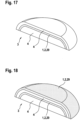
- a seventh embodiment of the basic structure 4 and reinforcement structure 1 is shown as a hybrid component 3.
- the Fig. 15 The basic structure 4 shown is manufactured or made available by a G-machine 41, for example manufactured by a 3D printer 44, manufactured by an injection molding machine or taken from a storage 45 as a magazine 46, that is to say merely made available.
- the basic structure 5 shown which is produced, for example, as a honeycomb structure, is Fig. 15 shown basic structure 4 with a conveyor system 43, for example a conveyor belt 47 or robot 48, to the PE machine 42.
- the reinforcing structures 1 are applied using the process unit 5 as the pultrusion and extrusion unit 6, 7.
- FIG. 16 A large number of rods 2 are placed next to one another without any gaps on the top of the Fig. 15 shown basic structure 4 and connected to the basic structure 4. Then the Fig. 16 The hybrid component 3 shown as the supporting structure 3 is transported back to the G-machine 41 as the 3D printer 44 or the injection molding machine. Here, an additional layer of the basic structure 4 is applied to the Fig. 16 Reinforcing structure 1 shown in Figure 1 is applied. After this manufacturing step, the supporting structure 3 has the Fig. 17 The geometry shown in the figure is then Fig. 17 The hybrid component 3 shown in FIG. 1 is then transported to the PE machine 42 with the conveyor system 43 and the reinforcing structure 1 is then applied.
- the manufacturing process can also be carried out in such a way that the hybrid component 3 is already produced as shown in FIG. 1.
- Fig. 16 represents the final finished product and no further manufacturing steps are carried out.
- the manufacturing method described in the seventh embodiment preferably also applies analogously to the first to sixth embodiments.
- a first embodiment of a machine system 40 is shown.
- a total of five 3D printers 44 as G machines 41 are combined with a PE machine 42, as a process unit 5 on a robot, to form the machine system 5.
- the cycle rate of each 3D printer 44 corresponds to approximately one fifth of the cycle rate of the PE machine 42.
- the sum of the cycle rates of the 3D printers 44 thus essentially corresponds to the cycle rate of just one PE machine 42.
- the basic structures 4 produced by the G machine 41 are transported to the PE machine 42 using the conveyor system 43, for example a conveyor belt 47 and/or a robot 48.
- the reinforcement structure 1 is applied to the basic structure 4 on the PE machine 42, so that the support structure 3 can be finally produced as the hybrid component 3 and is then removed at a removal point 49.
- a second embodiment of the machine system 40 is shown.
- An injection molding machine 50 as the G machine 41 is combined with three PE machines 42.
- the cycle rate of a PE machine 42 corresponds to approximately one third of the cycle rate of the injection molding machine 50.
- the injection molding machine 50 can, for example, produce thirty basic structures 4 in ten minutes and a PE machine 42 can apply or produce one reinforcement structure 1 for each basic structure 4 on ten basic structures 4 in ten minutes, i.e. produce ten reinforcement structures 1 in ten minutes.
- the sum of the cycle rates of the PE machines 42 thus corresponds to the cycle rate of the injection molding machine 50.
- both the injection molding machine 50 and the PE machines 42 are therefore constantly fully utilized.
- the conveyor system 43 is designed accordingly to transport the basic structures 4 from the injection molding machine 50 to the PE machines 42.
- the reinforcing structures 1 are made from the composite material 29 with fibers and a matrix.
- the process unit 5 is moved along a longitudinal axis of the reinforcing structure 1 to be produced, in particular rod 2, as a straight or curved movement path 26, so that the rods 2 can be produced from the composite material 29 at the required connection position on the surface of the basic structure 4 and the costs for producing the support structure 3 are thus significantly reduced.
- the proportion of the matrix and the fibers in the rods 2 is constant. By using a different number of hybrid yarns 21 or fibers to produce a rod 2 in each case, it is also possible to produce rods 2 with a different diameter.
- the rods 2 can also be produced in a different cross-sectional shape.
- the end of the extrusion channel 15 has a Fig. 1 not shown replaceable shaping part, so that bars 2 can also be easily manufactured as elliptical bars 2 or rectangular bars 2 or square bars 2 in the cross-sectional shape in addition to the circular shape described.
- the adaptation of the geometry and/or shape of the reinforcement structures 1 to different basic structures 4 with a wide variety of geometries can be carried out simply and inexpensively by the robot simply moving the process unit 5 on an adapted movement path 26.
- the robot either has sensors for detecting the geometry of the basic structure 4 and/or the geometry of the basic structure 4 is stored in a computing unit of the robot.
- the computing unit can calculate the movement path 26 for a given position for the at least one reinforcement structure 1.
- the adaptation of the geometry of the at least one reinforcement structure 1 to the geometry of the basic structure 4 can thus be carried out exclusively by program and/or data technology, because any movement paths 26 in space can be carried out with the robot.
- the adaptation or modification of the geometry and/or shape of the basic structures 4 can be carried out during production with the G-machine, in particular a 3D printer, exclusively by means of programming and/or data technology by means of a corresponding control of the G-machine with a computing unit.
- the number of G machines 41 is optimally adapted to the number of PE machines 42, i.e. due to the existing total cycle rates of the G machines 41 and PE machines 42, both the G machines 41 and the PE machines 42 are constantly essentially fully utilized during the production of the hybrid components 3.
- Unnecessary downtimes of a G machine 41 or a PE machine 42 on a larger scale can thus be advantageously avoided.
- the hybrid components 3 can be used for a wide variety of applications, for example in mechanical engineering as support structures 3 or in applications of daily use, for example as plates for eating or as shoe soles.
- the term supporting structure 3 is therefore to be interpreted broadly as a hybrid component 3 and a special load-bearing effect of the supporting structure 3 or the hybrid component 3 is not necessarily necessary.
Landscapes
- Engineering & Computer Science (AREA)
- Mechanical Engineering (AREA)
- Chemical & Material Sciences (AREA)
- Materials Engineering (AREA)
- Composite Materials (AREA)
- Physics & Mathematics (AREA)
- Manufacturing & Machinery (AREA)
- Optics & Photonics (AREA)
- Quality & Reliability (AREA)
- General Engineering & Computer Science (AREA)
- General Physics & Mathematics (AREA)
- Automation & Control Theory (AREA)
- Civil Engineering (AREA)
- Structural Engineering (AREA)
- Architecture (AREA)
- Robotics (AREA)
- Extrusion Moulding Of Plastics Or The Like (AREA)
- Moulding By Coating Moulds (AREA)
Description
- Die vorliegende Erfindung betrifft ein Verfahren zur Herstellung einer Tragstruktur als Hybridbauteil gemäß dem Oberbegriff des Anspruches 1 und ein Maschinensystem gemäß dem Oberbegriff des Anspruches 12.
- Tragstrukturen umfassen eine Grundstruktur und eine Verstärkungsstruktur. Als Grundstrukturen werden beispielsweise Stützen, Platten, Scheiben, Kuppeln oder Rotationsteilellipsoide eingesetzt. Um eine ausreichende Tragfähigkeit und Steifigkeit der Grundstrukturen zu erhalten, werden in aufwendiger Weise zuerst die Verstärkungsstrukturen, beispielsweise Streben, Platten, Scheiben oder Stangen, hergestellt und anschließend werden die Streben und Stangen mit der Grundstruktur verbunden, um die ausreichende Tragfähigkeit und Steifigkeit der Tragstruktur als Kombination aus Grundstruktur und wenigstens einer Verstärkungsstruktur zu erhalten. Außerdem können die Verstärkungsstrukturen nur mit einem großen Aufwand an unterschiedliche Geometrien von Grundstrukturen angepasst werden.
- Aus der
US 2014/0061974 A1 ist ein Verfahren zur Herstellung eines dreidimensionalen Objektes aus einem Verbundmaterial bekannt. Zwei oder mehr Materialien werden dabei gleichzeitig als ein Verbundmaterial extrudiert. - Die
DE 10 2015 007 317 A1 zeigt ein Verfahren zur Verstärkung einer Grundstruktur mit wenigstens einer Verstärkungsstruktur. Die Verstärkungsstrukturen werden bereits in der erforderlichen Verbindungsposition hergestellt, jedoch ist die Anzahl G-Maschinen fertigungstechnisch nicht optimal auf die Anzahl der der Prozesseinheiten als PE-Maschinen abgestimmt. Dadurch fallen hohe Maschinenkosten je hergestellte Tragstruktur an. Die Herstellung der Tragstrukturen ist damit teuer. - Die
DE 10 2014 006 706 A1 zeigt ein Verfahren zur Herstellung eines Fachwerkes. - In dem Artikel "Process choice and production layout", Management & Development Center, 11. April 2008, Seiten 1-16, 11-04-2008, Gefunden im Internet: RL:https://web.archive.org/web/20080411022735/ http://www.mdcegypt.com/Pages/Operation%20Management/Production%20 &%200peration%20Management/Facility%20Layout/Group%20Technology/ Process%20choice%20and%20production%20layout1.asp sind Möglichkeiten zur Auswahl bei Verfahren offenbart.
- Die Aufgabe der vorliegenden Erfindung besteht deshalb darin, ein Verfahren und ein Maschinensystem zur Herstellung eines Hybridbauteils zur Verfügung zu stellen, bei dem die Tragstruktur mit einem geringen technischen und finanziellen Aufwand je Tragstruktur hergestellt werden kann.
- Diese Aufgabe wird gelöst mit einem Verfahren gemäß Anspruch 1.
- Die pro Zeiteinheit von nur einer G-Maschine zur Verfügung gestellten Grundstrukturen und die von nur einer PE-Maschine pro Zeiteinheit hergestellten Verstärkungsstrukturen für je eine Grundstruktur können dadurch optimal aneinander angepasst werden. Die pro Zeiteinheit von nur einer G-Maschine zur Verfügung gestellten Grundstrukturen weist einen wesentlichen Unterschied auf zu der von nur einer PE-Maschine pro Zeiteinheit hergestellten Verstärkungsstrukturen für je eine Grundstruktur auf, insbesondere ist der Unterschied größer als 20%, 30% oder 50%. Die Taktzahl der G-Maschine unterscheidet sich somit von der Taktzahl der PE-Maschine. Aufgrund der unterschiedlichen Anzahlen an G-Maschinen und PE-Maschinen in dem Maschinensystem kann dadurch insgesamt in dem Maschinensystem die Taktzahl der G-Maschine auf die Taktzahl der PE-Maschine angepasst werden. Die Taktzahl einer G-Maschine ist die pro Zeiteinheit von einer G-Maschine zur Verfügung gestellten Grundstrukturen und in analoger Weise ist die Taktzahl der PE-Maschine die pro Zeiteinheit hergestellten Verstärkungsstrukturen für je eine Grundstruktur. Die Summe der Taktzahlen der in dem Maschinensystem vorhandenen wenigstens einen G-Maschinen entspricht im Wesentlichen der Summe der Taktzahlen der vorhandenen wenigstens einen PE-Maschine. Dadurch ist das Maschinensystem in vorteilhafter Weise optimiert ausgelegt, da größere unnötige Wartezeiten der hergestellten Grundstrukturen vor der Weiterverarbeitung in der PE-Maschine vermieden werden können. Das Maschinensystem ist damit insgesamt bezüglich der pro Zeiteinheit hergestellten Tragstrukturen kostengünstig, sodass in vorteilhafter Weise die Tragstrukturen als Hybridbauteile kostengünstig hergestellt werden können. Die Kosten für die Herstellung der Tragstruktur als Hybridbauteil können außerdem dadurch wesentlich reduziert werden, da die wenigstens eine Verstärkungsstruktur bereits an derjenigen Verbindungspositionen hergestellt wird, an welcher die wenigstens eine Verstärkungsstruktur mit der Grundstruktur zu verbinden bzw. befestigen ist. Eine aufwendige nachträgliche Anordnung bereits hergestellter Verstärkungsstrukturen an den erforderlichen Verbindungspositionen ist dadurch in vorteilhafter Weise nicht mehr erforderlich. Das Hybridbauteil umfasst wenigstens eine Grundstruktur und wenigstens eine Verstärkungsstruktur und die Hybrideigenschaft des Hybridbauteils resultiert aus der unterschiedlichen Taktzahl mit der die wenigstens eine Grundstruktur von der G-Maschine zur Verfügung, insbesondere hergestellt, wird und die wenigstens eine Verstärkungsstruktur mit der PE-Maschine hergestellt wird, wobei die wenigstens eine Grundstruktur und die wenigstens eine Verstärkungsstruktur im Regelfall unterschiedliche strukturelle Eigenschaften aufweisen, beispielsweise aus einem unterschiedlichen Material bzw. Werkstoff ausgebildet sind, jedoch kann die wenigstens Grundstruktur und die wenigstens eine Verstärkungsstruktur vorzugsweise auch identische strukturelle Eigenschaften aufweisen.
- In einer zusätzlichen Ausführungsform wird die Grundstruktur mit der wenigstens einen G-Maschine hergestellt und/oder eine Vielzahl an Grundstrukturen werden mit der wenigstens einen G-Maschine zur Verfügung gestellt und werden mit dem Fördersystem zu der wenigstens einen PE-Maschine transportiert und mit der wenigstens einen PE-Maschine werden die Verstärkungsstrukturen auf den Grundstrukturen hergestellt.
- In einer ergänzenden Ausgestaltung wird die Grundstruktur mit der wenigstens einen G-Maschine mittels Additive Manufacturing, insbesondere 3D-Drucken, vorzugsweise 3D-Drucken als Pulverbettverfahren und/oder Freiraumverfahren und/oder Flüssigmaterialverfahren, hergestellt und/oder die Grundstruktur wird mit der wenigstens einen G-Maschine mittels Spritzgießen hergestellt und/oder die Grundstruktur wird mit der wenigstens einen G-Maschine zur Verfügung gestellt, indem die Grundstruktur aus einem Speicher, insbesondere Magazin, entnommen wird.
- Zweckmäßig wird das 3D-Drucken als Pulverbettverfahren mittels selektives Laserschmelzen (SLM), selektiven Lasersintern (SLS), Selective Head Sintering (SHS), Binder Jetting und/oder Elektronenstrahlschmelzen ausgeführt und/oder das 3D-Drucken wird als Freiraumverfahren mittels Fused Deposition (FDM), Laminated Object Modelling (LOM), Auftragsschweißen bzw. Cladding, Wax Deposition Modeling (WDM), Contour Crafting, Kaltgasspritzen und/oder Elektronenstrahlschmelzen ausgeführt und/oder das 3D-Drucken wird als Flüssigmaterialverfahren mittels Stereolithografie (SLA), Digital Light Processing (DLP) oder Liquid Composite Moulding (LCM) ausgeführt.
- In einer zusätzlichen Ausgestaltung wird bzw. werden die von der wenigstens einen G-Maschine zur Verfügung gestellte Grundstruktur, insbesondere Grundstrukturen, mit einem Fördersystem als Förderband und/oder Roboter zu der wenigstens einen PE-Maschine transportiert.
- In einer weiteren Ausführungsform wird nach der Herstellung der wenigstens einen Verstärkungsstruktur auf der Grundstruktur die Grundstruktur mit der wenigstens einen Verstärkungsstruktur mit dem Fördersystem von der wenigstens einen PE-Maschine zu der wenigstens einen G-Maschine rücktransportiert und auf der bereits hergestellten Verstärkungsstruktur wird eine weitere Grundstruktur als zusätzliche Grundstruktur mit der wenigstens einen G-Maschine aufgebracht. Auf die weitere Grundstruktur als zusätzliche Grundstruktur kann in einem ergänzenden Herstellungsschritt von der PE-Maschine wenigstens eine weitere zusätzliche Verstärkungsstruktur aufgebracht werden bzw. auf der zusätzlichen Grundstruktur hergestellt werden und hierzu werden die miteinander verbundenen zwei Grundstrukturen mit der Verstärkungsstruktur von der G-Maschine wieder rücktransportiert zu der PE-Maschine. Diese Vorgänge können außerdem beliebig oft wiederholt werden, sodass dadurch die Tragstruktur als das Hybridbauteil eine beliebige Anzahl an Grundstrukturen und Verstärkungsstrukturen für je eine Grundstruktur aufweisen kann.
- In einer ergänzenden Ausgestaltung sind die pro Zeiteinheit von nur einer G-Maschine zur Verfügung gestellten Grundstrukturen kleiner als die von nur einer PE-Maschine pro Zeiteinheit hergestellten Verstärkungsstrukturen für je eine Grundstruktur und in dem Maschinensystem ist die Anzahl der wenigstens einen G-Maschine größer als die Anzahl der wenigstens einen PE-Maschine, insbesondere das Maschinensystem über nur eine PE-Maschine verfügt oder die pro Zeiteinheit von nur einer G-Maschine zur Verfügung gestellten Grundstrukturen sind größer als die von nur einer PE-Maschine pro Zeiteinheit hergestellten Verstärkungsstrukturen für je eine Grundstruktur und in dem Maschinensystem ist die Anzahl der wenigstens einen PE-Maschine größer als die Anzahl der wenigstens einen G-Maschine, insbesondere das Maschinensystem über nur eine G-Maschine verfügt.
- Zweckmäßig werden mit der G-Maschine unterschiedliche Grundstrukturen hergestellt und/oder mit der PE-Maschine werden unterschiedliche Verstärkungsstrukturen hergestellt und/oder das Verfahren wird mit einem in dieser Schutzrechtsanmeldung beschriebenen Maschinensystem ausgeführt. Die unterschiedlichen Grundstrukturen, welche von der G-Maschine hergestellt werden, weisen insbesondere eine unterschiedliche Geometrie und/oder Form auf. Diese unterschiedlichen Geometrien und/oder Formen sind einer Recheneinheit des Maschinensystems bekannt und aufgrund dieser unterschiedlicher Geometrien und/oder Formen der Grundstruktur wird entsprechend wenigstens eine unterschiedliche Verstärkungsstruktur für je eine Grundstruktur mittels der PE-Maschine auf die Grundstruktur aufgebracht bzw. hergestellt. Die unterschiedlichen Verstärkungsstrukturen weisen somit auch eine unterschiedliche Form und/oder Geometrie auf. Damit können mit dem Verfahren in vorteilhafter Weise auch unterschiedliche Tragstrukturen bzw. unterschiedliche Hybridbauteile in vorteilhafter Weise mit dem Maschinensystem hergestellt werden, indem lediglich die G-Maschine und die PE-Maschine von einer Recheneinheit entsprechend unterschiedlich gesteuert werden.
- In einer weiteren Ausführungsform wird bzw. werden mit der pultrudierten und/oder extrudierten wenigstens einen Verstärkungsstruktur, insbesondere sämtlichen Verstärkungsstrukturen, nach dem Pultrudieren und/oder Extrudieren und dem Auflegen auf die Grundstruktur keine Bewegung relativ zu der Grundstruktur ausgeführt und/oder die Matrix der pultrudierten und/oder extrudierten Verstärkungsstruktur, insbesondere sämtliche Verstärkungsstrukturen, an der erforderlichen Verbindungsposition an und/oder auf der Grundstruktur erhärtet und/oder die Pultrusion und Extrusion gleichzeitig und/oder kontinuierlich ausgeführt wird.
- In einer weiteren Ausgestaltung wird für die Herstellung der wenigstens einen Verstärkungsstruktur als erster Schritt das Pultrudieren ausgeführt und als zweiter Schritt wird das Extrudieren ausgeführt, so dass die in dem ersten Schritt teilweise hergestellte pultrudierte wenigstens eine Verstärkungsstruktur, insbesondere sämtliche Verstärkungsstrukturen, in dem zweiten Schritt mit Extrudieren nachbearbeitet wird bzw. werden und/oder die wenigstens eine Verstärkungsstruktur, vorzugsweise sämtliche Verstärkungsstrukturen, insbesondere kontinuierlich, hergestellt wird bzw. werden, indem die Pultrusionseinheit und/oder Extrusionseinheit, insbesondere kontinuierlich, im Raum in einer Bewegungsbahn bewegt wird an und/oder im Bereich der erforderlichen Verbindungsposition in einem Abstand zu der Grundstruktur. Der Abstand ist gering im Bereich weniger mm oder cm. Die Pultrusionseinheit und/oder Extrusionseinheit wird im Wesentlichen an der erforderlichen Verbindungsposition bewegt, da nach dem Austreten der wenigstens einen Verstärkungsstruktur aus der Prozesseinheit die Verstärkungsstruktur noch einen geringen Abstand zu der Grundstruktur aufweist.
- Zweckmäßig wird die wenigstens eine Verstärkungsstruktur als ein gerader oder gekrümmter Stab hergestellt und/oder die Bewegungsbahn im Wesentlichen eine Gerade und/oder, vorzugsweise gekrümmte, Linie ist und/oder die Pultrusionseinheit und/oder Extrusionseinheit mit einem Roboter bewegt wird und/oder nach dem Pultrudieren und/oder Extrudieren je einer Verstärkungsstruktur mit einer Schneideeinheit das Verbundmaterial mit den Fasen und der Matrix abgetrennt wird und/oder die wenigstens eine Verstärkungsstruktur als der Stab in seiner Länge zu mehr als 50%, 70%, 80% oder 90% an der Außenseite mit der Grundstruktur verbunden wird.
- In einer ergänzenden Variante wird je wenigstens eine Verstärkungsstruktur hergestellt deren Länge wenigstens um das 2-, 4-, 5-, 10- oder 20-Fache größer ist als der Durchmesser dieser Verstärkungsstruktur und/oder die Querschnittsform der wenigstens einen Verstärkungsstruktur, insbesondere sämtlicher Verstärkungsstrukturen, beim Extrudieren und/oder beim Auflegen auf die Grundstruktur ausgebildet wird bzw. werden und/oder die Länge der Verstärkungsstruktur, insbesondere sämtlicher Verstärkungsstrukturen, durch die Länge der Bewegungsbahn der Pultrusionseinheit und/oder Extrusionseinheit ausgebildet wird bzw. werden und/oder die wenigstens eine Verstärkungsstruktur, insbesondere sämtliche Verstärkungsstrukturen, ohne einem Hohlraum und/oder ohne einem Hohlkanal hergestellt werden. Beim Auflegen der wenigstens einen Verstärkungsstruktur auf die Grundstruktur ist das Verbundmaterial nicht vollständig abgekühlt und damit verformbar, so dass das Verbundmaterial an die Geometrie der Grundstruktur durch Verformen angepasst wird.
- In einer ergänzenden Ausgestaltung werden die Fasern und vorzugsweise die Matrix kontinuierlich zuerst durch die Pultrusionseinheit und anschließend durch die Extrusionseinheit gefördert und/oder Hybridgarne mit Fasern und Matrix werden zu der Pultrusionseinheit gefördert oder die Fasern und die Matrix werden getrennt zu der Pultrusionseinheit gefördert und/oder die Fasern oder die Hybridgarne von Rollen abgewickelt und zu der Pultrusionseinheit gefördert werden und/oder die wenigstens eine Verstärkungsstruktur, insbesondere sämtliche Verstärkungsstrukturen, herstellt wird bzw. werden, so dass wenigstens eine Faser, vorzugsweise mehrere Fasern, an einer Außenseite der wenigstens einen Verstärkungsstruktur, insbesondere sämtlicher Verstärkungsstrukturen, angeordnet ist bzw. sind und/oder die wenigstens eine Verstärkungsstruktur, insbesondere sämtliche Verstärkungsstrukturen, herstellt wird bzw. werden, so dass wenigstens eine Faser, vorzugsweise mehrere Fasern, keine vollständige Umhüllung mit der Matrix aufweist bzw. aufweisen und/oder die wenigstens eine Verstärkungsstruktur, insbesondere sämtliche Verstärkungsstrukturen, herstellt wird bzw. werden, so dass zwischen den Fasern die Matrix angeordnet ist. In den Verstärkungsstrukturen sind die Fasern mittels der Matrix stoffschlüssig miteinander fest verbunden, da die Matrix erhärtet ist. Die Fasern sind dabei auch an der Außenseite der wenigstens einen Verstärkungsstruktur angeordnet, so dass an der Außenseite der wenigstens einen Verstärkungsstruktur die Fasern sichtbar bzw. greifbar sind. Insbesondere sind somit nicht in einem inneren Bereich der Verstärkungsstrukturen die Fasern angeordnet und in einer äußeren Hülle die Matrix. Vielmehr sind die Fasern und die Matrix auf die Querschnittsform verteilt und zwischen den Fasern ist auch die Matrix angeordnet. Vorzugsweise umfasst dabei eine Verstärkungsstruktur, insbesondere Stab, beispielsweise wenigstens zwei, drei, fünf oder zehn Fasern.
- In einer zusätzlichen Ausführungsform werden in der Pultrusionseinheit während der Pultrusion mittels der Matrix die Fasern stoffschlüssig miteinander verbunden, insbesondere indem die Matrix erwärmt und/oder erhärtet wird und/oder die Matrix während des Fördern von der Pultrusionseinheit zu der Extrusionseinheit abgekühlt und/oder erhärtet wird, so dass dadurch die Fasern stoffschlüssig miteinander verbunden werden und/oder mittels einer Fördereinrichtung, beispielsweise zwei Förderrädern, die Fasern und die Matrix gefördert werden, insbesondere indem die Fördereinrichtung auf die Fasern mit der Matrix während des Fördern der Fasern mit der Matrix von der Pultrusionseinheit zu der Extrusionseinheit auf die Fasern mit der Matrix einwirkt und/oder die Fasern und die Matrix mittels Pultrusion zuerst stoffschlüssig, insbesondere mittels Erwärmen und/oder Erhärten der Matrix, miteinander verbunden werden und anschließend beim Extrudieren in der Extrusionseinheit wenigstens teilweise die Querschnittsform der wenigstens einen Verstärkungsstruktur ausgeformt wird und/oder die wenigstens eine Verstärkungsstruktur, insbesondere sämtliche Verstärkungsstrukturen, mit einem maximalen Durchmesser zwischen 1 mm und 30 mm, insbesondere zwischen 2 mm und 20 mm, extrudiert wird bzw. werden.
- In einer zusätzlichen Ausgestaltung werden in der Extrusionseinheit die Fasern mit der Matrix erwärmt und/oder in der Extrusionseinheit die Querschnittsform, vorzugsweise kreisförmig, ellipsenförmig oder rechteckig, der wenigstens einen Verstärkungsstruktur ausgeformt wird während des Extrudierens und vorzugsweise aufgrund des Kontaktes der wenigstens einen Verstärkungsstruktur mit der Oberfläche der Grundstruktur die Querschnittsform nochmals ausgeformt wird und/oder in der Pultrusionseinheit die Fasern mit der Matrix zuerst erwärmt werden, während des Förderns der Fasern mit der Matrix von der Pultrusionseinheit zu der Extrusionseinheit die Fasern abkühlen und in der Extrusionseinheit der Fasern mit der Matrix nochmals erwärmt werden und/oder die Fasern mit der Matrix in der Pultrusionseinheit mit einer, vorzugsweise ersten, Kühleinrichtung, aktiv gekühlt werden und/oder die Fasern mit der Matrix nach dem Fördern durch die Extrusionseinheit mit einer, vorzugsweise zweiten, Kühleinrichtung, beispielsweise einem Gebläse, aktiv gekühlt werden und/oder die wenigstens eine Verstärkungsstruktur, insbesondere sämtliche Verstärkungsstrukturen, bezüglich der Länge der jeweiligen Verstärkungsstruktur zu mehr als 70%, 80% oder 90% mit der Grundstruktur verbunden sind, so dass die Länge der Verbindung zwischen der Verstärkungsstruktur und der Grundstruktur größer ist als 70%, 80% oder 90% der Länge der Verstärkungsstruktur.
- In einer weiteren Ausgestaltung wird bzw. werden die wenigstens eine Verstärkungsstruktur, insbesondere sämtliche Verstärkungsstrukturen, mit Kunststoff, vorzugsweise thermoplastischen und/oder duroplastischen Kunststoff und/oder Kunststoff als reaktiver Hotmelt bzw. reaktiver Schmelzklebstoff bzw. reaktiver Schmelzpolymer, als Matrix hergestellt und/oder die wenigstens eine Verstärkungsstruktur, insbesondere sämtliche Verstärkungsstrukturen, mit Fasern als Glasfasern, Karbonfasern und/oder Aramidfasern, hergestellt wird bzw. werden und/oder die wenigstens eine Verstärkungsstruktur, insbesondere sämtliche Verstärkungsstrukturen, ausschließlich aus Matrix und Fasern hergestellt wird bzw. werden und/oder die wenigstens eine Verstärkungsstruktur, insbesondere sämtliche Verstärkungsstrukturen, hergestellt wird bzw. werden, so dass der Massenanteil oder Volumenanteil der Fasern wenigstens 30%, 40%, 60% oder 80% beträgt und/oder die wenigstens eine Verstärkungsstruktur, insbesondere sämtliche Verstärkungsstrukturen, hergestellt wird bzw. werden, so dass der Massenanteil oder Volumenanteil der Matrix weniger als 70%, 60%, 40% oder 20% beträgt und/oder die wenigstens eine Verstärkungsstruktur, insbesondere sämtliche Verstärkungsstrukturen, hergestellt wird bzw. werden, so dass die wenigstens eine Verstärkungsstruktur ausschließlich aus den Fasern und der Matrix ausgebildet ist bzw. sind. Kunststoffe als reaktiver Hotmelt bzw. reaktiver Schmelzklebstoff bzw. reaktiver Schmelzpolymer sind Kunststoffe die, vorzugsweise zunächst thermoplastische Eigenschaften aufweisen und/oder ein thermoplastischer Kunststoff sind, und nach wenigstens einem Veränderungsparameter, beispielsweise das Erwärmen bzw. Erhitzen und/oder das Aussetzten an Feuchtigkeit und/oder der Bestrahlung mit UV-Licht und/oder einem Sauerstoffentzug, durch eine chemische Veränderung, insbesondere wenigstens eine chemische Reaktion, duroplastische Eigenschaften aufweisen und/oder ein duroplastischer Kunststoff sind. Bei einem Veränderungsparameter des Erwärmens bzw. Erhitzens kann das Erwärmen und/oder Erhitzen in der Pultrusionseinheit und/oder Extrusionseinheit als Veränderungsparameter genutzt werden und nach dem anschließenden Abkühlen und Erhärten der Matrix auf der Grundstruktur weist die Tragstruktur, insbesondere die Verstärkungsstruktur, auch bei einem Erwärmen oder Erhitzen eine ausreichende Tragfähigkeit und/oder Steifigkeit auf. Duroplastische Kunststoffe sind auch bei einem Erwärmen bzw. Erhitzen zu 100% ein Festkörper, d. h. das Erhärten ist nicht durch Erwärmen umkehrbar. Das Erwärmen und/oder Erhitzen in der Pultrusionseinheit und/oder Extrusionseinheit wird beispielsweise auf Temperaturen zwischen 60°C und 200° C ausgeführt. Bei einem reaktiven Hotmelt beispielsweise auf Basis von Polymeren wird die chemische Veränderung durch eine Verbindung zwischen bestehenden Makromolekularketten (sog. Cross links) ausgeführt. Reaktive Hotmelts sind beispielsweise auf Basis von EVA (Ethylen-Vinyl-Acetat) und Polyester oder auf Basis von PA (Polyamid) oder auf Basis von Polymeren oder auf Basis von PUR aufgebaut. Reaktive Hotmelts können auch teilweise Stoffe aufweisen, die keine Kunststoffe bzw. Klebstoffe sind. Klebstoffe werden insofern auch als Kunststoffe betrachtet. Wesentliche Eigenschaft des reaktiven Hotmelts bzw. reaktiven Schmelzklebstoffes bzw. reaktiven Schmelzpolymers ist somit, dass nach dem Erhärten aufgrund des Einwirkens des wenigstens einen Veränderungsparameters ein Erwärmen der wenigstens einen Verstärkungsstruktur kein Schmelzen des reaktiven Hotmelts bzw. der Matrix aus dem reaktiven Hotmelt bewirkt, so dass trotz des Erwärmens auf für die Anwendung normale Temperaturen, beispielsweise auf Temperaturen bis 200° C oder 300° C, die Tragfähigkeit und/oder Steifigkeit der Tragstruktur weiterhin gewährleistet ist.
- In einer weiteren Ausgestaltung wird bzw. werden die wenigstens eine Verstärkungsstruktur, insbesondere sämtliche Verstärkungsstrukturen, hergestellt, so dass die Länge der Fasern, insbesondere sämtlicher Fasern, in je einer Verstärkungsstruktur im Wesentlichen der Länge der wenigstens einen Verstärkungsstruktur entspricht und/oder die wenigstens eine Verstärkungsstruktur, insbesondere sämtliche Verstärkungsstrukturen, auf der Oberfläche der Grundstruktur abkühlen und erhärten. Im Wesentlichen bedeutet dabei, dass die Länge der Verstärkungsstruktur mit einer Abweichung von weniger als 30%, 20%, 10% oder 5% der Länge der Fasern in der jeweiligen Verstärkungsstruktur entspricht.
- In einer weiteren Ausführungsform wird vor dem Auflegen der wenigstens einen Verstärkungsstruktur auf die Oberfläche der Grundstruktur an der Oberfläche der Grundstruktur lokal im Bereich einer späteren Kontaktfläche zwischen der wenigstens einen Verstärkungsstruktur und der Grundstruktur der Werkstoff der Grundstruktur abgetragen.
- Vorzugsweise wird die Grundstruktur spanabhebend abgetragen, insbesondere mit einem Werkzeug, vorzugsweise Fräswerkzeug, und das Werkzeug wird von einem Roboter entlang der Oberfläche der Grundstruktur bewegt.
- In einer zusätzlichen Variante wird in die Grundstruktur aufgrund des Abtragens des Werkstoffes der Grundstruktur eine, vorzugsweise längliche, Aussparung eingearbeitet und in die Aussparung wird anschließend die wenigstens eine Verstärkungsstruktur eingeführt, so dass eine formschlüssige Verbindung zwischen der wenigstens einen Verstärkungsstruktur und der Grundstruktur an der Aussparung, insbesondere nach dem Abkühlen und Erhärten der Matrix, ausgebildet wird. Die Aussparungen können beispielsweise beim Herstellen der Grundstrukturen mit einem 3D-Drucker bereits beim Herstellen mit dem 3D-Drucker durch eine entsprechende Steuerung des 3D-Druckers mit einer Recheneinheit mit herstellt werden.
- In einer ergänzenden Ausgestaltung wird vor dem Auflegen der wenigstens einen Verstärkungsstruktur auf die Oberfläche der Grundstruktur die Oberfläche der Grundstruktur lokal im Bereich einer späteren Kontaktfläche zwischen der wenigstens einen Verstärkungsstruktur und der Grundstruktur mit einer Grundstrukturheizeinrichtung, insbesondere einem Laser oder einem Infrarotstrahler, erwärmt.
- In einer weiteren Ausführungsform wird die Grundstrukturheizeinrichtung von einem Roboter entlang der Oberfläche der Grundstruktur bewegt und/oder aufgrund des Erwärmens der Oberfläche der Grundstruktur wird lokal im Bereich einer späteren Kontaktfläche zwischen der wenigstens einen Verstärkungsstruktur und der Grundstruktur der Werkstoff der Grundstruktur seine Eigenschaft verändert, insbesondere zähfließend und/oder klebrig und/oder flüssig, so dass eine stoffschlüssige Verbindung zwischen der Matrix der wenigstens einen Verstärkungsstruktur und dem Werkstoff der Grundstruktur, insbesondere nach dem Abkühlen, ausgebildet wird.
- In einer ergänzenden Ausgestaltung wird vor dem Auflegen der wenigstens einen Verstärkungsstruktur auf die Oberfläche der Grundstruktur lokal im Bereich einer späteren Kontaktfläche zwischen der wenigstens einen Verstärkungsstruktur und der Grundstruktur mit einer Zugabevorrichtung ein Stoff, insbesondere ein Klebstoff und/oder ein Haftvermittler, zur Verbesserung der Verbindung zwischen der wenigstens einen Verstärkungsstruktur und der Grundstruktur aufgebracht.
- Vorzugsweise wird die Zugabevorrichtung von einem Roboter entlang der Oberfläche der Grundstruktur bewegt.
- In einer ergänzenden Ausgestaltung wird zuerst die Grundstruktur hergestellt oder zur Verfügung gestellt und anschließend wird die wenigstens eine Verstärkungsstruktur hergestellt.
- Zweckmäßig wird die Grundstruktur mit einem anderen Verfahren hergestellt als die wenigstens eine Verstärkungsstruktur.
- Ein erfindungsgemäßes Maschinensystem ist gemäß Anspruch 12 ausgeführt.
- Die Anzahl der wenigstens einen G-Maschine und die Anzahl der wenigstens einen PE-Maschine ist an die Taktzahl aus der Summe der wenigstens einen G-Maschine und der Summe der wenigstens einen PE-Maschine dahingehend angepasst, dass die Summe der Taktzahlen der wenigstens G-Maschine im Wesentlichen, das heißt mit einer Abweichung von weniger als 60 %, 50 %, 40 %, 30 %, 20 % oder 10 %, der Summe der Taktzahlen der wenigstens einen PE-Maschine entspricht. Die wenigstens eine G-Maschine und die wenigstens eine PE-Maschine ist damit im Betrieb des Maschinensystems zur Herstellung der Tragstruktur als das Hybridbauteil im Wesentlichen ständig ausgelastet. Dadurch weist das Maschinensystem geringe Kosten zur Herstellung je einer Tragstruktur auf.
- In einer ergänzenden Ausgestaltung ist die G-Maschine ein 3D-Drucker und/oder eine Spritzgussmaschine und/oder ein Speicher für die Grundstrukturen und/oder das Fördersystem ist ein Förderband und/oder ein Roboter.
- In einer zusätzlichen Variante umfasst das Maschinensystem einen Roboter zum Bewegen der PE-Maschine in einer Bewegungsbahn im Raum und die PE-Maschine an dem Roboter befestigst ist, so dass die wenigstens eine Verstärkungsstruktur in der erforderlichen Verbindungsposition auf der wenigstens einen Grundstruktur herstellbar ist.
- Zweckmäßig ist das Maschinensystem dahingehend ausgebildet, dass die pro Zeiteinheit von nur einer G-Maschine zur Verfügung gestellten Grundstrukturen kleiner sind als von nur einer PE-Maschine pro Zeiteinheit hergestellten Verstärkungsstrukturen für je eine Grundstruktur und in dem Maschinensystem die Anzahl der wenigstens einen G-Maschine größer ist als die Anzahl der wenigstens einen PE-Maschine, insbesondere das Maschinensystem über nur eine PE-Maschine verfügt oder das Maschinensystem ist dahingehend ausgebildet, dass die pro Zeiteinheit von nur einer G-Maschine zur Verfügung gestellten Grundstrukturen größer sind als von nur einer PE-Maschine pro Zeiteinheit hergestellten Verstärkungsstrukturen für je eine Grundstruktur und in dem Maschinensystem die Anzahl der wenigstens einen PE-Maschine größer ist als die Anzahl der wenigstens einen G-Maschine, insbesondere das Maschinensystem über nur eine G-Maschine verfügt.
- Zweckmäßig ist die Grundstruktur aus Metall, insbesondere Stahl und/oder Aluminium, und/oder aus Kunststoff, insbesondere faserverstärkten Kunststoff, und/oder in Sandwichbauweise aus zwei unterschiedlichen Materialien ausgebildet.
- In einer weiteren Variante ist die Grundstruktur als ein flächiges Bauteil, eine Platte, eine Scheibe, eine Teilkugelschale, eine Kuppel, ein Rotationsteilellipsoid, eine Wanne oder ein Becher ausgebildet.
- In einer zusätzlichen Ausgestaltung ist die Grundstruktur und/oder die Tragstruktur ein tragendes Bauteil, beispielsweise ein Träger, eine Stütze, eine Strebe, ein Flansch, eine Kuppel, eine Platte, eine Scheibe, eine Teilkugelschale, eine Schuhsohle, ein Teller, eine Tischplatte, eine Wandung oder eine Decke, für verschiedenste Anwendungen, insbesondere im Alltagsleben, Maschinenbau, Bauwesen oder Elektrotechnik.
- In einer ergänzenden Ausführungsform wird die wenigstens eine Verstärkungsstruktur mit einer ebenen und/oder gekrümmten Oberfläche der Grundstruktur verbunden, vorzugsweise indem die wenigstens eine Verstärkungsstruktur mittels Extrusion und/oder Pultrusion an und/oder auf der ebenen und/oder gekrümmten Oberfläche der Grundstruktur hergestellt wird.
- In einer zweckmäßigen Ausgestaltung ist die wenigstens eine Verstärkungsstruktur, vorzugsweise sämtliche Verstärkungsstrukturen, mit Kunststoff, vorzugsweise thermoplastischen Kunststoff und/oder duroplastischen Kunststoff und/oder Kunststoff als reaktiver Hotmelt bzw. reaktiver Schmelzklebstoff bzw. reaktiver Schmelzpolymer, als Matrix ausgebildet und/oder die wenigstens eine Verstärkungsstruktur, vorzugsweise sämtliche Verstärkungsstrukturen, sind mit Fasern als Glasfasern, Karbonfasern und/oder Aramidfasern, ausgebildet und/oder die wenigstens eine Verstärkungsstruktur, vorzugsweise sämtliche Verstärkungsstrukturen, ist bzw. sind ausschließlich aus Fasern und Matrix ausgebildet und/oder der Massenanteil oder Volumenanteil der Fasern an der wenigstens eine Verstärkungsstruktur, vorzugsweise sämtliche Verstärkungsstrukturen, beträgt wenigstens 30%, 40%, 60% oder 80% und/oder der Massenanteil oder Volumenanteil der Matrix an der wenigstens einen Verstärkungsstruktur, vorzugsweise sämtlichen Verstärkungsstrukturen, beträgt weniger als 70%, 60%, 40% oder 20% und/oder die wenigstens eine Verstärkungsstruktur, vorzugsweise sämtliche Verstärkungsstrukturen, sind ausschließlich aus den Fasern und der Matrix ausgebildet und/oder die wenigstens eine Verstärkungsstruktur, vorzugsweise sämtliche Verstärkungsstrukturen, sind gerade und/oder gekrümmt ausgebildet und/oder die Länge der wenigstens eine Verstärkungsstruktur, vorzugsweise sämtliche Verstärkungsstrukturen, ist wenigstens um das 2-, 4-, 5-, 10- oder 20-Fache größer als der Durchmesser der wenigstens eine Verstärkungsstruktur, vorzugsweise sämtliche Verstärkungsstrukturen, und/oder die wenigstens eine Verstärkungsstruktur, vorzugsweise sämtliche Verstärkungsstrukturen, sind ohne Hohlraum ausgebildet und/oder an der wenigstens eine Verstärkungsstruktur, vorzugsweise sämtliche Verstärkungsstrukturen, ist an der Außenseite wenigstens eine Faser angeordnet bzw. sind vorzugsweise mehrere Fasern angeordnet, so dass vorzugsweise die wenigstens eine Faser, vorzugsweise die mehreren Fasern, an der Außenseite der wenigstens einen Verstärkungsstruktur, vorzugsweise sämtliche Verstärkungsstrukturen, sichtbar und/oder greifbar ist bzw. sind und/oder wenigstens eine Faser, vorzugsweise mehrere Fasern, an der wenigstens eine Verstärkungsstruktur, vorzugsweise sämtliche Verstärkungsstrukturen, keine vollständige Umhüllung mit der Matrix aufweist bzw. aufweisen und/oder die Fasern sind mit zwischen den Fasern angeordneter Matrix stoffschlüssig miteinander verbunden.
- Die Erfindung umfasst ferner ein Computerprogramm mit Programmcodemitteln, die auf einem computerlesbaren Datenträger gespeichert sind, um ein in dieser Schutzrechtsanmeldung beschriebenes Verfahren durchzuführen, wenn das Computerprogramm auf einem Computer oder einer entsprechenden Recheneinheit durchgeführt wird.
- Bestandteil der Erfindung ist außerdem ein Computerprogrammprodukt mit Programmcodemitteln, die auf einem computerlesbaren Datenträger gespeichert sind, um ein in dieser Schutzrechtsanmeldung beschriebenes Verfahren durchzuführen, wenn das Computerprogramm auf einem Computer oder einer entsprechenden Recheneinheit durchgeführt wird.
- Im Nachfolgenden werden Ausführungsbeispiele der Erfindung unter Bezugnahme auf die beigefügten Zeichnungen näher beschrieben.
- Es zeigt:
- Fig. 1
- einen vereinfachten Längsschnitt einer Prozesseinheit als PE-Maschine mit einer Pultrusionseinheit und Extrusionseinheit zur Durchführung des Verfahrens,
- Fig. 2
- eine Seitenansicht der Prozesseinheit während der Durchführung des Verfahrens,
- Fig. 3
- einen Querschnitt einer Grundstruktur vor dem Aufbringen einer Verstärkungsstruktur,
- Fig. 4
- den Querschnitt der Grundstruktur gemäß
Fig. 3 nach dem Aufbringen der Verstärkungsstruktur, - Fig. 5
- einen Querschnitt von Grundstrukturen und Verstärkungsstrukturen in einem ersten Ausführungsbeispiel,
- Fig. 6
- den Querschnitt von Grundstrukturen und Verstärkungsstrukturen in einem zweiten Ausführungsbeispiel,
- Fig. 7
- eine Draufsicht auf eine Grundstruktur und Verstärkungsstrukturen in einem dritten Ausführungsbeispiel,
- Fig. 8
- eine perspektivische Ansicht der Grundstruktur mit Verstärkungsstrukturen gemäß
Fig. 7 , - Fig. 9
- eine Draufsicht auf eine Grundstruktur und Verstärkungsstrukturen in einem vierten Ausführungsbeispiel,
- Fig. 10
- eine perspektivische Ansicht der Grundstruktur mit Verstärkungsstrukturen gemäß
Fig. 9 , - Fig. 11
- eine Draufsicht auf eine Grundstruktur und Verstärkungsstrukturen in einem fünften Ausführungsbeispiel,
- Fig. 12
- eine perspektivische Ansicht der Grundstruktur mit Verstärkungsstrukturen gemäß
Fig. 11 , - Fig. 13
- eine Seitenansicht auf eine Grundstruktur und Verstärkungsstrukturen in einem sechsten Ausführungsbeispiel,
- Fig. 14
- eine perspektivische Ansicht der Grundstruktur mit Verstärkungsstrukturen gemäß
Fig. 13 , - Fig. 15
- eine perspektivische Ansicht auf eine Grundstruktur in einem siebten Ausführungsbeispiel,
- Fig. 16
- eine perspektivische Ansicht auf eine Grundstruktur mit Verstärkungsstruktur gemäß
Fig. 15 , - Fig. 17
- eine perspektivische Ansicht auf eine Grundstruktur mit Verstärkungsstruktur und einer zusätzlichen Grundstruktur gemäß
Fig. 15 , - Fig. 18
- eine perspektivische Ansicht auf eine Grundstruktur mit Verstärkungsstruktur und einer zusätzlichen Grundstruktur und einer zusätzlichen Verstärkungsstruktur gemäß
Fig. 15 , - Fig. 19
- eine stark vereinfachte Darstellung eines Maschinensystems in einem ersten Ausführungsbeispiel und
- Fig. 20
- eine stark vereinfachte Darstellung eines Maschinensystems in einem zweiten Ausführungsbeispiel.
- In
Fig. 1 und2 ist eine Prozesseinheit 5 zur Herstellung einer Verstärkungsstruktur 1 dargestellt. Die Prozesseinheit 5 umfasst eine Pultrusionseinheit 6 und eine Extrusionseinheit 7 und bildet eine PE-Maschine 42. In der Pultrusionseinheit 6 ist ein Pultrusionskanal 9 ausgebildet und in einer Richtung von rechts nach links gemäß der Darstellung inFig. 1 weist der Pultrusionskanal 9 zunächst einen konisch sich verjüngenden Abschnitt und anschließend einen Abschnitt mit einem konstanten Durchmesser auf. An dem Pultrusionskanal 9 in dem Abschnitt mit dem konstanten Durchmesser ist in einer Richtung gemäß der Darstellung inFig. 1 von rechts nach links sowie in einer Förderrichtung von Hybridgarnen 21 bzw. der herzustellenden bzw. hergestellten Verstärkungsstruktur 1 zuerst eine erste Heizeinrichtung 8 angeordnet und anschließend eine erste Kühleinrichtung 10. An der ersten Kühleinrichtung 10 ist ein Kühlkanal 11 ausgebildet, durch den ein Kühlfluid durchgeleitet wird zur Kühlung der teilweise hergestellten Verstärkungsstruktur 1. Die Extrusionseinheit 7 umfasst einen Extrusionskanal 15 und der Extrusionskanal 15 umfasst einen ersten sich konisch verjüngenden Abschnitt und einen zweiten Abschnitt mit einem konstanten Durchmesser. An dem zweiten Abschnitt des Extrusionskanales 15 mit dem konstanten Durchmesser ist eine zweite Heizeinrichtung 16 ausgebildet. Die erste und zweite Heizeinrichtung 8, 16 ist vorzugsweise als eine elektrische Widerstandsheizung ausgebildet. In der Förderrichtung der herzustellenden Verstärkungsstruktur 1 durch den Extrusionskanal 15 ist zuerst der konisch sich verjüngende Abschnitt des Extrusionskanales 15 und anschließend der Abschnitt des Extrusionskanales 15 mit dem konstanten Durchmesser ausgebildet. Zwischen der Pultrusionseinheit 6 und der Extrusionseinheit 7 ist eine Fördereinrichtung 12 ausgebildet. Die Fördereinrichtung 12 umfasst ein erstes Förderrad 13 und ein zweites Förderrad 14, welche von einem nicht dargestellten Elektromotor angetrieben werden. Die teilweise hergestellte Verstärkungsstruktur 1 ist zwischen den beiden Förderräden 13, 14 angeordnet, so dass die teilweise hergestellte Verstärkungsstruktur 1 mit der Fördereinrichtung 12 aus der Pultrusionseinheit 6 herausgezogen wird und mit der Fördereinrichtung 12 in die Extrusionseinheit 7 eingeschoben wird. - Die Pultrusionseinheit 6 und die Extrusionseinheit 7 sind mit einem Verbindungsteil 20, beispielsweise einem in
Fig. 1 nur teilweise dargestellten Gehäuse, miteinander verbunden. An dem Verbindungsteil 20 ist ferner ein Zuführungsteil 23 mit drei Führungsbohrungen 24 befestigt. Auf drei Rollen 22 ist jeweils ein Hybridgarn 21 aufgerollt. Das Hybridgarn 21 besteht aus einer Faser als Glasfaser und weist ferner die Matrix aus einem thermoplastischen Kunststoff auf. Die Matrix als dem thermoplastischen Kunststoff ist dabei in dem Hybridgarn 21 als eine faserförmige Matrix bzw. als eine Matrixfaser angeordnet. Das Hybridgarn 21 ist biegbar und kann somit von der Rolle 22 abgerollt werden. An der Extrusionseinheit 7 ist ferner eine zweite Kühleinheit 17 befestigt. Die zweite Kühleinheit 17 umfasst ein Gebläse 18 und ein Kühlrohr 19. Mittels des Gebläses 18 wird Umgebungsluft durch das Kühlrohr 19 geleitet, gezielt zu dem Bereich der Verstärkungsstruktur 1 unmittelbar nach dem Verlassen der Extrusionseinheit 7. Eine Schneideeinheit 25 dient dazu, die an der Extrusionseinheit 7 extrudierte Verstärkungsstruktur 1 soweit erforderlich abzuschneiden und dadurch ein Ende der Verstärkungsstruktur 1 herstellen zu können. - Während der Herstellung der Verstärkungsstruktur 1 aus dem Verbundmaterial 29 mit den Fasern und der Matrix wird das Verbundmaterial 29 gemäß der Darstellung in
Fig. 1 zuerst durch die Pultrusionseinheit 6 und anschließend durch die Extrusionseinheit 7 mittels der Fördereinrichtung 12 gefördert, jedoch erfolgen beide Vorgänge aufgrund der Länge der Stäbe 2 und Abstandes zwischen der Pultrusionseinheit 6 und der Extrusionseinheit 7 gleichzeitig. Während des Förderns des Verbundmateriales 29 wird somit der Hybridgarn 21 von den drei Rollen 22 abgerollt und in den konisch sich verjüngenden Abschnitt des Pultrusionskanales 9 eingeführt. An dem zweiten Abschnitt des Pultrusionskanales 9 mit dem konstanten Durchmesser werden die drei Hybridgarne 21 mit der ersten Heizeinrichtung 8 erwärmt, so dass der thermoplastische Kunststoff der Matrix an den Hybridgarnen 21 schmilzt und dadurch die Glasfasern in den drei Hybridgarnen 21 mittels der Matrix aus dem thermoplastischen Kunststoff stoffschlüssig miteinander verbunden werden als Pultrusionsvorgang. Anschließend wird das Verbundmaterial 29 mit den Fasern und der Matrix zu dem Abschnitt des Pultrusionskanales 9 mit der ersten Kühleinrichtung 10 gefördert bzw. bewegt, so dass dadurch das Verbundmaterial 29 mit den Glasfasern und dem thermoplastischen Kunststoff abgekühlt und dadurch erhärtet wird. Nach dem Austreten des Verbundmateriales 29 aus den Fasern und der Matrix wird das Verbundmaterial 29 mit der Matrix aus der bereits teilweise hergestellten Verstärkungsstruktur 1 von der Fördereinrichtung 12 in die Extrusionseinheit 7 eingefördert bzw. hineingeführt. Aufgrund des Abkühlens des Verbundmateriales 29 mit den Fasern in der ersten Kühleinrichtung 10 kann das Verbundmaterial 29 mit den Fasern von der Fördereinrichtung 12 gefördert werden. In der Extrusionseinheit 7 wird das Verbundmaterial 29 mit den Fasern und der Matrix an dem Abschnitt des Extrusionskanales 15 mit dem konstanten Durchmesser von der zweiten Heizeinrichtung 16 wieder geringfügig soweit erwärmt, dass an dem Endbereich in der Förderrichtung des Extrusionskanales 15 die abschließende Formgebung der Querschnittsform der herzustellenden Verstärkungsstruktur 1 ausgeformt wird. Das inFig. 1 linke Ende des Extrusionskanales 15 weist eine kreisförmige oder quadratische Querschnittsform auf, so dass dadurch mittels der Prozesseinheit 5 Verstärkungsstrukturen 1 mit einem kreisförmigen oder quadratischen Querschnitt hergestellt werden. Nach dem Austreten der Verstärkungsstrukturen 1 aus dem Extrusionskanal 15 der Extrusionseinheit 7 wird von dem Gebläse 18 durch das Kühlrohr 19 Umgebungsluft als Kühlluft zu dem Stab 2 geleitet, so dass dadurch eine schnellere Abkühlung der Verstärkungsstrukturen 1 erreicht werden kann. - Die mit dem Verfahren hergestellten Verstärkungsstrukturen 1 sind als gerade oder gekrümmte Stäbe 2 ausgebildet. Die Stäbe 2 werden von der Prozesseinheit 5 an den erforderlichen Verbindungsposition auf einer Grundstruktur 4 hergestellt, so dass die Prozesseinheit 5 auf einer Bewegungsbahn 26 als einer Geraden 27 oder gekrümmten Linie 27 mittels Bewegungsarmen 28 eines in
Fig. 2 stark vereinfacht dargestellten Roboters bewegt wird. Die Bewegungsbahn 26 als Gerade 27 oder gekrümmte Linie 27 entspricht dabei im Wesentlichen der Längsachse der von der Prozesseinheit 5 hergestellten Verstärkungsstruktur 1. Nach der Herstellung der Stäbe 2 und dem Auflegen der Stäbe 2 bzw. der Verstärkungsstrukturen 1 auf die Oberfläche der Grundstruktur 4 ist keine Relativbewegung bzw. Bewegung der hergestellten Stäbe 2 zu anderen bereits hergestellten oder noch herzustellenden Stäbe 2 oder zu der Grundstruktur 2 erforderlich, da die Stäbe 2 mit der Prozesseinheit 5 bereits an der erforderlichen Verbindungsposition auf der Grundstruktur 4 hergestellt werden. Dadurch können die Kosten für die Herstellung einer Tragstruktur 3 mit der Grundstruktur 4 und Verstärkungsstrukturen 1 mittels der Prozesseinheit 5 wesentlich reduziert werden. InFig. 2 sind die Rollen 22 und die Hybridgarne 21 nicht dargestellt. Die Verstärkungsstruktur 1 besteht aus Stäben 2 aus dem Verbundmaterial 29, nämlich mit Fasern als Glasfasern und der Matrix als thermoplastischen Kunststoff. - In einem weiteren, nicht dargestellten Ausführungsbeispiel der Prozesseinheit 5 sind an den Rollen 22 die Fasern, z. B. Glas-, Aramid- oder Karbonfasern, aufgewickelt und die Matrix als dem thermoplastischen Kunststoff wird gesondert in einem Behälter mit einer Behälterheizung in einem erwärmten Zustand aufbewahrt und mittels einer nicht dargestellter Matrixfördereinrichtung zu der Pultrusionseinheit 6 gefördert. Die Pultrusionseinheit 6 und die Extrusionseinheit 7 kann auch als nur ein Bauteil ausgebildet sein, indem beispielsweise nach dem Pultrudieren unmittelbar das Extrudieren, d. h. die abschließende Formgebung einer Außenseite 33 des Stabe 2 ausgeführt wird, ohne dass die Fördereinrichtung 12 zwischen der Extrusionseinheit 7 und der Pultrusionseinheit 6 angeordnet ist.
- In einem weiteren, nicht dargestellten Ausführungsbeispiel wird anstelle von thermoplastischem Kunststoff als der Matrix ein duroplastischer Kunststoff oder ein Kunststoff als ein reaktiver Hotmelt bzw. reaktiver Schmelzklebstoff bzw. reaktiver Schmelzpolymer eingesetzt. Der duroplastische Kunststoff wird gesondert in einem Behälter gelagert und mittels einer Matrixfördereinrichtung der Extrusionseinheit 7 und/oder der Pultrusionseinheit 6 zugeführt. Das Erhärten des duroplastischen Kunststoffes erfolgt dabei mittels einer Bestrahlung oder einer Zugabe von chemischen Additiven. Das Erhärten des Kunststoffes als reaktiver Hotmelt bzw. reaktiver Schmelzklebstoff bzw. reaktiver Schmelzpolymer wird insbesondere durch das Erwärmen als Veränderungsparameter während der Verarbeitung der Matrix in der Pultrusionseinheit 6 und/oder in der Extrusionseinheit 7 ausgeführt. Abweichend hiervon kann das Erhärten des Kunststoffes als reaktiver Hotmelt auch durch Feuchtigkeit und/oder UV-Licht und/oder Sauerstoffentzug ausgeführt werden. Bei einer Erhärtung durch UV-Licht erfolgt somit nach der Auflegen der wenigstens einen Verstärkungsstruktur 1 auf die Grundstruktur 4 eine Bestrahlung der wenigstens einen Verstärkungsstruktur 1 mit UV-Licht mittels einer UV-Lichtquelle (nicht dargestellt).
- An der Prozesseinheit 5 sind Vorbearbeitungseinrichtungen 34, 36, 38 als ein Werkzeug 34 als ein Fräswerkzeug 35, eine Grundstrukturheizeinrichtung 36, beispielsweise ein Laser 37 oder ein Infrarotstrahler 38, und eine Zugabevorrichtung 39 für Klebstoff 31 befestigt (nur in
Fig. 2 dargestellt). Das Werkzeug 34, die Grundstrukturheizeinrichtung 36 und die Zugabevorrichtung 39 sind mit mechanischen Einrichtungen relativ zu der Prozesseinheit 5 beweglich, so dass die Vorbearbeitungseinrichtungen 34, 36, 38 an unterschiedliche Bewegungsbahnen 26 mit unterschiedlichen Oberflächen von Grundstrukturen 4 in der erforderlichen Position angeordnet werden können. Vor dem Auflegen der an der Prozesseinheit 5 hergestellten Verstärkungsstruktur 1 auf die Oberfläche der Grundstruktur 4 wird mit dem Fräswerkzeug 35 eine längliche Aussparung 32 (Fig. 3 ) mit einer beliebigen Querschnittsform, abhängig von der Geometrie des Fräswerkzeuges 35, in die Grundstruktur 4 eingefräst. Die Aussparungen 32 weisen dabei einen Hinterschnitt auf, so dass nach dem Abkühlen und Erhärten des Verbundmateriales 29 mit den Fasern und der Matrix innerhalb der Aussparung 32 eine formschlüssige Verbindung der Stäbe 2 als Verstärkungsstruktur 1 an der Grundstruktur 1, beispielsweise Platten 30, ausgebildet ist. - Anschließend wird die Oberfläche der Grundstruktur 4 im Bereich der Aussparung 32 mit der Grundstrukturheizeinrichtung 36 erwärmt, so dass sich die Matrix des Verbundmateriales 29 stoffschlüssig mit dem Werkstoff der Grundstruktur 4 verbinden kann und nach dem Abkühlen und Erhärten des Verbundmateriales 29 und der Grundstruktur 4 eine feste stoffschlüssige Verbindung zwischen der Grundstruktur 4 und der Verstärkungsstruktur 1 besteht.
- Anschließend wird mit der Zugabevorrichtung 39 auf die Oberfläche der Grundstruktur 4 im Bereich der Aussparung 32 Klebstoff 31 aufgebracht, um nach dem Auflegen der Verstärkungsstruktur 1 auf die Grundstruktur 4 und dem Erhärten des Klebstoffes 31 die Verstärkungsstruktur 1 stoffschlüssig mit der Grundstruktur 4 zu verbinden. Im Allgemeinen wird abhängig vom Werkstoff der Grundstruktur 4 nur die Grundstrukturheizeinrichtung 36 oder nur die Zugabevorrichtung 39 betrieben. Bei einer Grundstruktur 4 aus Metall, beispielsweise Stahl oder Aluminium, wird nur die Zugabevorrichtung 39 und nicht die Grundstrukturheizeinrichtung 36 betrieben. Bei einer Grundstruktur 4 aus thermoplastischen Kunststoff wird nicht die Zugabevorrichtung 39 und nur die Grundstrukturheizeinrichtung 36 betrieben.
- In
Fig. 5 ist ein Querschnitt von Grundstrukturen 4 und Verstärkungsstrukturen 1 als Tragstruktur 3 bzw. Hybridbauteil 3 in einem ersten Ausführungsbeispiel dargestellt. Die Grundstrukturen 4 weisen eine gerade Oberfläche auf und die Grundstrukturen 4 und Verstärkungsstrukturen 1 sind schichtartig übereinander ausgebildet. Beispielsweise wird eine Schicht der Grundstruktur 4 mit einem 3D-Drucker hergestellt und anschließend die Verstärkungsstruktur 1 mit der Prozesseinheit 5. Die Stäbe 2 können auch ohne eine Abstand a zwischen zwei benachbarten Stäben 2 in einer Richtung senkrecht zu der Zeichenebene vonFig. 5 auf die Oberfläche der Grundstruktur 4 extrudiert werden, so dass auch die Verstärkungsstruktur 1 eine scheibenförmige Geometrie aufweisen kann. - In
Fig. 6 ist ein Querschnitt von Grundstrukturen 4 und Verstärkungsstrukturen 1 als Tragstruktur 3 in einem zweiten Ausführungsbeispiel dargestellt. Die Grundstrukturen 4 weisen eine gekrümmte Oberfläche auf und die Grundstrukturen 4 und Verstärkungsstrukturen 1 sind schichtartig übereinander ausgebildet, so dass auch die Verstärkungsstrukturen 1 gekrümmt ausgebildet sind. - In
Fig. 7 ist eine Draufsicht auf die Grundstruktur 4 und Verstärkungsstrukturen 1 als Hybridbauteil 3 und inFig. 8 eine perspektivische Ansicht der Grundstruktur 4 mit Verstärkungsstrukturen 1 in einem dritten Ausführungsbeispiel dargestellt. Die Grundstruktur 4 weist eine gerade Oberfläche auf, so dass auch die Verstärkungsstrukturen 1 gerade sind. Die Verstärkungsstrukturen 1 weisen parallel zu der Zeichenebene vonFig. 7 einen Abstand a auf. Die stabförmigen Verstärkungsstrukturen 1 weisen eine Länge L auf als Längsausdehnung in einer Längsachse der Verstärkungsstrukturen 1. - In
Fig. 9 ist eine Draufsicht auf die Grundstruktur 4 und Verstärkungsstrukturen 1 als Tragstruktur 3 und inFig. 10 eine perspektivische Ansicht der Grundstruktur 4 mit Verstärkungsstrukturen 1 in einem vierten Ausführungsbeispiel dargestellt. Die Grundstruktur 4 weist eine gerade Oberfläche auf, so dass auch die Verstärkungsstrukturen 1 gerade sind. Die Verstärkungsstrukturen 1 weisen parallel zu der Zeichenebene vonFig. 9 einen Abstand a auf. - In
Fig. 11 ist eine Draufsicht auf die Grundstruktur 4 und Verstärkungsstrukturen 1 als Hybridbauteil 3 und inFig. 12 eine perspektivische Ansicht der Grundstruktur 4 mit Verstärkungsstrukturen 1 in einem fünften Ausführungsbeispiel dargestellt. Die Grundstruktur 4 weist eine gerade Oberfläche auf, so dass auch die Verstärkungsstrukturen 1 gerade sind. Die Verstärkungsstrukturen 1 weisen parallel zu der Zeichenebene vonFig. 7 einen Abstand a auf und ferner sind einzelne extrudierte Stäbe 2 stoffschlüssig ohne Abstand a miteinander verbunden indem die Prozesseinheit 5 mit einer entsprechenden Bewegungsbahn 26 bewegt wird. Zum stoffschlüssigen Verbinden der Stäbe 2 werden diese dahingehend extrudiert, dass die Matrix noch nicht abgekühlt ist und/oder die bereits extrudierten Stäbe 2 für die stoffschlüssige Verbindung erwärmt werden. - In
Fig. 13 ist eine Seitenansicht auf die Grundstruktur 4 und Verstärkungsstrukturen 1 als Tragstruktur 3 und inFig. 14 eine perspektivische Ansicht der Grundstruktur 4 mit Verstärkungsstrukturen 1 in einem sechsten Ausführungsbeispiel dargestellt. Die Grundstruktur 4 weist eine gekrümmte Oberfläche auf, so dass auch die Verstärkungsstrukturen 1 gekrümmt sind. Die Verstärkungsstrukturen 1 sind teilweise in Aussparungen 32 der Grundstruktur 4 angeordnet. - In den
Fig. 15 bis 18 ist ein siebtes Ausführungsbeispiel der Grundstruktur 4 und Verstärkungsstruktur 1 als Hybridbauteil 3 dargestellt. Die inFig. 15 dargestellte Grundstruktur 4 wird von einer G-Maschine 41 hergestellt bzw. zur Verfügung gestellt, beispielsweise von einem 3D-Drucker 44 hergestellt, von einer Spritzgussmaschine hergestellt oder aus einem Speicher 45 als einem Magazin 46 entnommen, das heißt lediglich zur Verfügung gestellt. Bei der Herstellung der inFig. 15 dargestellten Grundstruktur 5, die beispielsweise als eine Wabenstruktur hergestellt wird, wird die inFig. 15 dargestellte Grundstruktur 4 mit einem Fördersystem 43, beispielsweise einem Förderband 47 oder Roboter 48, zu der PE-Maschine 42 transportiert. In der PE-Maschine 42 werden mit der Prozesseinheit 5 als der Pultrusions- und Extrusionseinheit 6, 7 die Verstärkungsstrukturen 1 aufgebracht. Dabei werden eine Vielzahl von Stäben 2 ohne Abstand nebeneinander auf die Oberseite der inFig. 15 dargestellten Grundstruktur 4 aufgebracht und mit der Grundstruktur 4 verbunden. Anschließend wird das inFig. 16 dargestellte Hybridbauteil 3 als die Tragstruktur 3 wieder zu der G-Maschine 41 als der 3D-Drucker 44 oder der Spritzgussmaschine transportiert. Hier wird eine zusätzliche Schicht der Grundstruktur 4 auf die inFig. 16 dargestellte Verstärkungsstruktur 1 aufgebracht. Nach diesem Herstellungsschritt weist die Tragstruktur 3 die inFig. 17 dargestellte Geometrie auf. Anschließend wird nach diesem Herstellungsschritt das inFig. 17 dargestellte Hybridbauteil 3 wiederum zu der PE-Maschine 42 mit dem Fördersystem 43 transportiert und anschließend wiederum die Verstärkungsstruktur 1 aufgebracht werden. Der Herstellungsvorgang kann auch dahingehend erfolgen, dass bereits das Hybridbauteil 3 gemäß der Darstellung inFig. 16 das endgültige Fertigprodukt darstellt und keine weiteren Herstellungsschritte ausgeführt werden. Die in dem siebten Ausführungsbeispiel beschriebene Herstellungsweise gilt vorzugsweise auch analog für das erste bis sechste Ausführungsbeispiel. - In
Fig. 19 ist ein erstes Ausführungsbeispiel eines Maschinensystems 40 dargestellt. Insgesamt fünf 3D-Drucker 44 als G-Maschinen 41 sind mit einer PE-Maschine 42, als eine Prozesseinheit 5 an einem Roboter, zu dem Maschinensystem 5 kombiniert. Die Taktzahl je eines 3D-Druckers 44 entspricht ungefähr einem Fünftel der Taktzahl der PE-Maschine 42. Die Summe der Taktzahlen der 3D-Drucker 44 entspricht somit im Wesentlichen der Taktzahl der nur einen PE-Maschine 42. Die von der G-Maschine 41 hergestellten Grundstrukturen 4 werden mit dem Fördersystem 43, beispielsweise einem Förderband 47 und/oder einem Roboter 48, zu der PE-Maschine 42 transportiert. An der PE-Maschine 42 wird auf die Grundstruktur 4 die Verstärkungsstruktur 1 aufgebracht, sodass dadurch die Tragstruktur 3 als das Hybridbauteil 3 endgültig hergestellt werden kann und anschließend an einer Entnahmestelle 49 entnommen wird. - In
Fig. 20 ist ein zweites Ausführungsbeispiel des Maschinensystems 40 dargestellt. Eine Spritzgussmaschine 50 als die G-Maschine 41 ist mit drei PE-Maschinen 42 kombiniert. Die Taktzahl einer PE-Maschine 42 entspricht ungefähr einem Drittel der Taktzahl der Spritzgussmaschine 50. Die Spritzgussmaschine 50 kann beispielsweise in zehn Minuten dreißig Grundstrukturen 4 herstellen und eine PE-Maschine 42 kann in zehn Minuten auf zehn Grundstrukturen 4 je eine Verstärkungsstruktur 1 für je eine Grundstruktur 4 aufbringen bzw. herstellen, das heißt in zehn Minuten zehn Verstärkungsstrukturen 1 herstellen. Die Summe der Taktzahlen der PE-Maschinen 42 entspricht somit der Taktzahl der Spritzgussmaschine 50. Im Betrieb des Maschinensystems 40 sind somit sowohl die Spritzgussmaschine 50 als auch die PE-Maschinen 42 ständig voll ausgelastet. Das Fördersystem 43 ist entsprechend ausgelegt, um die Grundstrukturen 4 von der Spritzgussmaschine 50 zu den PE-Maschinen 42 zu transportieren. - Insgesamt betrachtet sind mit dem erfindungsgemäßen Verfahren zur Verstärkung der Grundstruktur 4 wesentliche Vorteile verbunden. Die Verstärkungsstrukturen 1 sind aus dem Verbundmaterial 29 mit Fasern und einer Matrix hergestellt. Die Prozesseinheit 5 wird dabei während der Herstellung entlang einer Längsachse der herzustellenden Verstärkungsstruktur 1, insbesondere Stabes 2, als eine gerade oder gekrümmte Bewegungsbahn 26 bewegt, so dass dadurch die Stäbe 2 aus dem Verbundmaterial 29 an der erforderlichen Verbindungsposition bereits auf der Oberfläche der Grundstruktur 4 hergestellt werden können und dadurch die Kosten für die Herstellung der Tragstruktur 3 wesentlich reduziert sind. Bei einem Einsatz des Hybridgarnes 21 ist der Anteil von der Matrix und den Fasern in den Stäben 2 konstant. Durch den Einsatz einer unterschiedlichen Anzahl an Hybridgarnen 21 bzw. Fasern zur Herstellung jeweils eines Stabes 2 ist es auch möglich, Stäbe 2 mit einem unterschiedlichen Durchmesser herzustellen. Ferner können die Stäbe 2 auch in einer unterschiedlichen Querschnittsform hergestellt werden. Hierzu weist das Ende des Extrusionskanales 15 ein in
Fig. 1 nicht dargestelltes austauschbares Formgebungsteil auf, so dass dadurch auch Stäbe 2 neben der beschriebenen Kreisform auch als ellipsenförmige Stäbe 2 oder rechteckförmige Stäbe 2 oder quadratische Stäbe 2 in der Querschnittsform einfach hergestellt werden können. Die Anpassung der Geometrie und/oder Form der Verstärkungsstrukturen 1 an unterschiedliche Grundstrukturen 4 mit unterschiedlichsten Geometrien kann einfach und preiswert dadurch erfolgen, dass der Roboter die Proesseinheit 5 lediglich auf einer angepassten Bewegungsbahn 26 bewegt. Hierzu weist der Roboter entweder Sensoren zur Erfassung der Geometrie der Grundstruktur 4 auf und/oder die Geometrie der Grundstruktur 4 ist in einer Recheneinheit des Roboters gespeichert. Aufgrund der Daten zur Geometrie der Grundstruktur 4 kann mit der Recheneinheit die Bewegungsbahn 26 berechnet werden bei vorgegebener Position für die wenigstens eine Verstärkungsstruktur 1. Die Anpassung der Geometrie der wenigstens eine Verstärkungsstruktur 1 an die Geometrie der Grundstruktur 4 kann somit ausschließlich programm- und/oder datentechnisch ausgeführt werden, weil mit dem Roboter beliebige Bewegungsbahnen 26 im Raum ausgeführt werden können. Die Anpassung oder Veränderung der Geometrie und/oder Form der Grundstrukturen 4 kann beim Herstellen mit der G-Maschine, insbesondere einem 3D-Drucker, ausschließlich programm- und/oder datentechnisch ausgeführt werden mittels einer entsprechenden Steuerung der G-Maschine mit einer Recheneinheit. - In dem Maschinensystem 40 ist die Anzahl der G-Maschinen 41 an die Anzahl der PE-Maschinen 42 optimal angepasst, das heißt aufgrund der vorhandenen Summen an Taktzahlen der G-Maschinen 41 und PE-Maschinen 42 sind sowohl die G-Maschinen 41 als auch die PE-Maschinen 42 während der Herstellung der Hybridbauteile 3 ständig im Wesentlichen ausgelastet. Dadurch fallen in vorteilhafter Weise für die Herstellung der Hybridbauteile 3 je Hybridbauteil 3 geringe Maschinenkosten an. Unnötige Ruhezeiten einer G-Maschine 41 oder einer PE-Maschine 42 in einem größeren Umfang können dadurch in vorteilhafter Weise vermieden werden. Die Hybridbauteile 3 können für die unterschiedlichsten Anwendungen eingesetzt werden, beispielsweise im Maschinenbau als Tragstrukturen 3 oder auch in Anwendungen des täglichen Lebensbedarfs, beispielsweise als Teller zum Essen oder als Schuhsohlen. Der Begriff der Tragstruktur 3 ist somit breit als ein Hybridbauteil 3 auszulegen und eine spezielle Tragwirkung der Tragstruktur 3 bzw. des Hybridbauteils 3 ist nicht zwangsweise notwendig.
Claims (15)
- Verfahren zur Herstellung einer Tragstruktur (3) als Hybridbauteil (3) mit einer Grundstruktur (4) und mit wenigstens einer Verstärkungsstruktur (1) mit den Schritten:- Herstellen der wenigstens einen Verstärkungsstruktur (1) für je eine Grundstruktur (4),- zur Verfügung stellen der Grundstruktur (4) mit einer G-Maschine (41), welche eine Maschine zur Zurverfügungstellung der Grundstruktur ist,- Verbinden der wenigstens einen Verstärkungsstruktur (1) mit der Grundstruktur (4), so dass die wenigstens eine Verstärkungsstruktur (1) in einer Verbindungsposition mit der Grundstruktur (4) verbunden ist und die Grundstruktur (4) zusammen mit der wenigstens einen Verstärkungsstruktur (1) die Tragstruktur (3) bildet,wobei, das Herstellen der wenigstens einen Verstärkungsstruktur (1) für je eine Grundstruktur (4) ausgeführt wird indem die wenigstens eine Verstärkungsstruktur (1), aus einem Verbundmaterial mit Fasern und einer Matrix mittels Pultrusion und/oder mit Extrusion hergestellt wird bzw. werden und eine Pultrusionseinheit (6) und/oder eine Extrusionseinheit (7) als PE-Maschine (42) zur Herstellung der Verstärkungsstruktur (1) im Raum bewegt wird, so dass die wenigstens eine Verstärkungsstruktur (1), nach der Pultrusion und/oder Extrusion jeweils an der erforderlichen Verbindungsposition auf die Grundstruktur (4) pultrudiert und/oder extrudiert wird bzw. werden und die wenigstens eine Verstärkungsstruktur (1), bezüglich der Länge der jeweiligen Verstärkungsstruktur (1) zu mehr als 50% mit der Grundstruktur (4) verbunden sind, so dass die Länge der Verbindung zwischen der Verstärkungsstruktur (1) und der Grundstruktur (4) größer ist als 50% der Länge der Verstärkungsstruktur (1)
unddas Verfahren mit einem Maschinensystem (40) ausgeführt wird und in dem Maschinensystem (40) die Anzahl der wenigstens einen G-Maschine (41) und die Anzahl der wenigstens einen PE-Maschine (42) unterschiedlich sind und die von der wenigstens einen G-Maschine (41) zur Verfügung gestellte Grundstruktur (4) mit einem Fördersystem (43) zu der wenigstens einen PE-Maschine (42) transportiert wird. - Verfahren nach Anspruch 1,
dadurch gekennzeichnet, dassdie Grundstruktur (4) mit der wenigstens einen G-Maschine (41) hergestellt wird und/odereine Vielzahl an Grundstrukturen (4) mit der wenigstens einen G-Maschine (41) zur Verfügung gestellt werden und mit dem Fördersystem (43) zu der wenigstens einen PE-Maschine (42) transportiert werden und mit der wenigstens einen PE-Maschine (42) die Verstärkungsstrukturen (1) auf den Grundstrukturen (4) hergestellt werden. - Verfahren nach Anspruch 1 oder 2,
dadurch gekennzeichnet, dass
die wenigstens eine Verstärkungsstruktur (1), bezüglich der Länge der jeweiligen Verstärkungsstruktur (1) zu mehr als 70%, 80% oder 90% mit der Grundstruktur (4) verbunden sind, so dass die Länge der Verbindung zwischen der Verstärkungsstruktur (1) und der Grundstruktur (4) größer ist als 70%, 80% oder 90% der Länge der Verstärkungsstruktur (1). - Verfahren nach einem oder mehreren der vorhergehenden Ansprüche,
dadurch gekennzeichnet, dass
die pro Zeiteinheit von nur einer G-Maschine (41) zur Verfügung gestellten Grundstrukturen (4) einen Unterschied aufweisen zu der von nur einer PE-Maschine (42) pro Zeiteinheit hergestellten Verstärkungsstrukturen (1) für je eine Grundstruktur (4), welcher größer ist als 20%, 30% oder 50%. - Verfahren nach einem oder mehreren der vorhergehenden Ansprüche,
dadurch gekennzeichnet, dass
die von der wenigstens einen G-Maschine (41) zur Verfügung gestellte Grundstruktur (4), insbesondere Grundstrukturen (4), mit einem Fördersystem (43) als Förderband (47) und/oder Roboter (48) zu der wenigstens einen PE-Maschine (42) transportiert wird bzw. werden. - Verfahren nach einem oder mehreren der vorhergehenden Ansprüche,
dadurch gekennzeichnet, dass
nach der Herstellung der wenigstens einen Verstärkungsstruktur (1) auf der Grundstruktur (4) die Grundstruktur (4) mit der wenigstens einen Verstärkungsstruktur (1) mit dem Fördersystem (43) von der wenigstens einen PE-Maschine (42) zu der wenigstens einen G-Maschine (41) rücktransportiert wird und auf der bereits hergestellten Verstärkungsstruktur (1) eine weitere Grundstruktur (4) als zusätzliche Grundstruktur (4) mit der wenigstens einen G-Maschine (41) aufgebracht wird. - Verfahren nach einem oder mehreren der vorhergehenden Ansprüche,
dadurch gekennzeichnet, dassdie pro Zeiteinheit von nur einer G-Maschine (41) zur Verfügung gestellten Grundstrukturen (4) kleiner sind als die von nur einer PE-Maschine (42) pro Zeiteinheit hergestellten Verstärkungsstrukturen (1) für je eine Grundstruktur (4) und in dem Maschinensystem (40) die Anzahl der wenigstens einen G-Maschine (41) größer ist als die Anzahl der wenigstens einen PE-Maschine (42), insbesondere das Maschinensystem (40) über nur eine PE-Maschine (42) verfügt
oderdie pro Zeiteinheit von nur einer G-Maschine (41) zur Verfügung gestellten Grundstrukturen (4) größer sind als die von nur einer PE-Maschine (42) pro Zeiteinheit hergestellten Verstärkungsstrukturen (1) für je eine Grundstruktur (4) und in dem Maschinensystem (40) die Anzahl der wenigstens einen PE-Maschine (42) größer ist als dieAnzahl der wenigstens einen G-Maschine (41), insbesondere das Maschinensystem (40) über nur eine G-Maschine (41) verfügt. - Verfahren nach einem oder mehreren der vorhergehenden Ansprüche,
dadurch gekennzeichnet, dassmit der G-Maschine (41) unterschiedliche Grundstrukturen (4) hergestellt werden
und/odermit der PE-Maschine (42) unterschiedliche Verstärkungsstrukturen (1) hergestellt werden
und/oderdas Verfahren mit einem Maschinensystem (40) gemäß einem oder mehrere der Ansprüche 12 bis 15 ausgeführt wird. - Verfahren nach einem oder mehreren der vorhergehenden Ansprüche,
dadurch gekennzeichnet, dassmit der pultrudierten und/oder extrudierten wenigstens einen Verstärkungsstruktur (1), nach dem Pultrudieren und/oder Extrudieren und dem Auflegen auf die Grundstruktur (4) keine Bewegung relativ zu der Grundstruktur (4) ausgeführt wird bzw. werden
und/oderdie Matrix der pultrudierten und/oder extrudierten Verstärkungsstruktur (1), an der erforderlichen Verbindungsposition an und/oder auf der Grundstruktur (4) erhärtet
und/oderdie Pultrusion und Extrusion gleichzeitig und/oder kontinuierlich ausgeführt wird. - Verfahren nach einem oder mehreren der vorhergehenden Ansprüche,
dadurch gekennzeichnet, dassfür die Herstellung der wenigstens einen Verstärkungsstruktur (1) als erster Schritt das Pultrudieren ausgeführt wird und als zweiter Schritt das Extrudieren ausgeführt wird, so dass die in dem ersten Schritt teilweise hergestellte pultrudierte wenigstens eine Verstärkungsstruktur (1), in dem zweiten Schritt mit Extrudieren nachbearbeitet wird bzw. werden
und/oderdie wenigstens eine Verstärkungsstruktur (1), vorzugsweise sämtliche Verstärkungsstrukturen (1), insbesondere kontinuierlich, hergestellt wird bzw. werden, indem die Pultrusionseinheit (6) und/oder Extrusionseinheit (7), insbesondere kontinuierlich, im Raum in einer Bewegungsbahn (26) bewegt wird an der erforderlichen Verbindungsposition in einem Abstand zu der Grundstruktur (4). - Verfahren nach einem oder mehreren der vorhergehenden Ansprüche,
dadurch gekennzeichnet, dass
die wenigstens eine Verstärkungsstruktur (1) als Stab (2) in seiner Länge zu mehr als 50%, 70%, 80% oder 90% an der Außenseite (33) mit der Grundstruktur (4) verbunden wird. - Maschinensystem (40) zur Herstellung einer Tragstruktur (3) als Hybridbauteil (3) mit einer Grundstruktur (4) und mit wenigstens einer Verstärkungsstruktur (1), umfassend- wenigstens eine G-Maschine (41) zur Verfügung stellen der Grundstruktur (4),- wenigstens eine PE-Maschine (42) mit einer Pultrusionseinheit (6) und/oder einer Extrusionseinheit (7) zur Herstellung der wenigstens einen Verstärkungsstruktur (1),dadurch gekennzeichnet, dass
die Anzahl der wenigstens einen G-Maschine (41) und die Anzahl der wenigstens einen PE-Maschine (42) unterschiedlich sind und das Maschinensystem (40) ein Fördersystem (43) zum Transportieren der Grundstruktur (4) von der G-Maschine (41) zu der PE-Maschine (42) umfasst und das Maschinensystem (40) eingerichtet ist ein Verfahren gemäß einem oder mehrerer der Ansprüche 1 bis 11 auszuführen. - Maschinensystem nach Anspruch 12,
dadurch gekennzeichnet, dassdie G-Maschine (41) ein 3D-Drucker (44) und/oder eine Spritzgussmaschine und/oder ein Speicher (45) für die Grundstrukturen (4) ist
und/oderdas Fördersystem (43) ein Förderband (47) und/oder ein Roboter (48) ist. - Maschinensystem nach Anspruch 12 oder 13,
dadurch gekennzeichnet, dass
das Maschinensystem (40) einen Roboter zum Bewegen der PE-Maschine (42) in einer Bewegungsbahn im Raum umfasst und die PE-Maschine (42) an dem Roboter befestigst ist, so dass die wenigstens eine Verstärkungsstruktur (1) in der erforderlichen Verbindungsposition auf der wenigstens einen Grundstruktur (4) herstellbar ist. - Maschinensystem nach einem oder mehreren der Ansprüche 12 bis 14,
dadurch gekennzeichnet, dassdas Maschinensystem (40) dahingehend ausgebildet ist, dass die pro Zeiteinheit von nur einer G-Maschine (41) zur Verfügung gestellten Grundstrukturen (4) kleiner sind als von nur einer PE-Maschine (42) pro Zeiteinheit hergestellten Verstärkungsstrukturen (1) für je eine Grundstruktur (4) und in dem Maschinensystem (40) die Anzahl der wenigstens einen G-Maschine (41) größer ist als die Anzahl der wenigstens einen PE-Maschine (42), insbesondere das Maschinensystem (40) über nur eine PE-Maschine (42) verfügt,
oderdas Maschinensystem (40) dahingehend ausgebildet ist, dass die pro Zeiteinheit von nur einer G-Maschine (41) zur Verfügung gestellten Grundstrukturen (4) größer sind als von nur einer PE-Maschine (42) pro Zeiteinheit hergestellten Verstärkungsstrukturen (1) für je eine Grundstruktur (4) und in dem Maschinensystem (40) die Anzahl der wenigstens einen PE-Maschine (42) größer ist als die Anzahl der wenigstens einen G-Maschine (41), insbesondere das Maschinensystem (40) über nur eine G-Maschine (41) verfügt.
Applications Claiming Priority (2)
| Application Number | Priority Date | Filing Date | Title |
|---|---|---|---|
| DE102015013915.0A DE102015013915A1 (de) | 2015-10-27 | 2015-10-27 | Maschinensystem zur Herstellung eines Hybridbauteils |
| PCT/EP2016/001690 WO2017071794A1 (de) | 2015-10-27 | 2016-10-12 | Maschinensystem zur herstellung eines hybridbauteils |
Publications (2)
| Publication Number | Publication Date |
|---|---|
| EP3368259A1 EP3368259A1 (de) | 2018-09-05 |
| EP3368259B1 true EP3368259B1 (de) | 2024-12-04 |
Family
ID=57199932
Family Applications (1)
| Application Number | Title | Priority Date | Filing Date |
|---|---|---|---|
| EP16785346.4A Active EP3368259B1 (de) | 2015-10-27 | 2016-10-12 | Maschinensystem zur herstellung eines hybridbauteils |
Country Status (4)
| Country | Link |
|---|---|
| US (1) | US10870241B2 (de) |
| EP (1) | EP3368259B1 (de) |
| DE (1) | DE102015013915A1 (de) |
| WO (1) | WO2017071794A1 (de) |
Families Citing this family (11)
| Publication number | Priority date | Publication date | Assignee | Title |
|---|---|---|---|---|
| DE102017209457A1 (de) * | 2017-06-02 | 2018-12-06 | Faurecia Innenraum Systeme Gmbh | Verfahren und Werkzeug zum Herstellen eines Fahrzeuginnenverkleidungsteils sowie Fahrzeuginnenverkleidungsteil |
| DE102017217763A1 (de) * | 2017-10-06 | 2019-04-11 | Thyssenkrupp Ag | Verfahren zur Herstellung von Hybridbauteilen sowie Verwendungen solcher Hybridbauteile |
| US11411095B2 (en) | 2017-11-30 | 2022-08-09 | Intel Corporation | Epitaxial source or drain structures for advanced integrated circuit structure fabrication |
| TW202524711A (zh) | 2017-11-30 | 2025-06-16 | 美商英特爾股份有限公司 | 用於先進積體電路結構製造之異質金屬線組成 |
| FR3079446A1 (fr) * | 2018-03-27 | 2019-10-04 | Francois Geli | Procede de renforcement de plaque thermoplastique |
| DE102019106260A1 (de) * | 2019-03-12 | 2020-09-17 | HELLA GmbH & Co. KGaA | Verfahren zur Herstellung einer Fügeverbindung zwischen einem lichttechnisch wirksamen Kunststoffbauteil und einer Metallkomponente |
| US11173654B2 (en) * | 2019-04-10 | 2021-11-16 | Northrop Grumman Systems Corporation | Method for fabricating multi-material structure for 3D integrated composite structures |
| DE102019206435A1 (de) * | 2019-05-06 | 2020-11-12 | Schäfer MWN GmbH | Mehrpunktlenker für ein Fahrwerk eines Fahrzeugs |
| DE102019206436A1 (de) * | 2019-05-06 | 2020-11-12 | Schäfer MWN GmbH | Mehrpunktlenker für ein Fahrwerk eines Fahrzeugs |
| EP3772546B1 (de) * | 2019-08-05 | 2022-01-26 | Siemens Aktiengesellschaft | Herstellen einer struktur mittels eines kaltgasspritzverfahrens |
| DE102019215665A1 (de) * | 2019-10-11 | 2021-04-15 | Sgl Carbon Se | Kunststofffaserverbundbauteile |
Family Cites Families (17)
| Publication number | Priority date | Publication date | Assignee | Title |
|---|---|---|---|---|
| US5091036A (en) | 1989-10-05 | 1992-02-25 | Taylor Scott R | Apparatus for pultruding thermoplastic structures at below melt temperatures |
| EP0742862A4 (de) | 1993-01-21 | 1997-02-26 | David W Johnson | System für eine zieh-stranggespresste verbindungsstelle für elektrische energie übertragende masten und andere grosse konstruktionen |
| US5358397A (en) | 1993-05-10 | 1994-10-25 | L&L Products, Inc. | Apparatus for extruding flowable materials |
| US6644535B2 (en) | 2001-05-18 | 2003-11-11 | Massachusetts Institute Of Technology | Truss core sandwich panels and methods for making same |
| US20030035913A1 (en) * | 2001-08-16 | 2003-02-20 | Shobert Benjamin A. | Pultrude linear bearing material |
| US20050276945A1 (en) | 2004-06-09 | 2005-12-15 | Muggli Mark W | Composite articles and methods of making the same |
| DE202004011250U1 (de) | 2004-07-17 | 2004-10-07 | Rehau Ag + Co. | Vorrichtung zur Herstellung von Formteilen |
| WO2009055580A2 (en) | 2007-10-24 | 2009-04-30 | University Of Southern California | Contour crafting extrusion nozzles |
| DE102006008728B3 (de) | 2006-02-24 | 2007-07-19 | Airbus Deutschland Gmbh | Verfahren zur Herstellung eines räumlichen Stabwerks als Kernstruktur einer Sandwichkonstruktion |
| US7809457B2 (en) * | 2007-10-30 | 2010-10-05 | Gm Global Technology Operations, Inc. | Framework for automatic generation of sequence of operations |
| US9128476B2 (en) * | 2007-12-21 | 2015-09-08 | The Invention Science Fund I, Llc | Secure robotic operational system |
| DE102008043031A1 (de) | 2008-10-22 | 2010-04-29 | BSH Bosch und Siemens Hausgeräte GmbH | Verfahren zur Herstellung eines faserverstärkten Kunststoffprofiles |
| DE102012109671B4 (de) | 2012-03-16 | 2016-09-29 | Institut Für Verbundwerkstoffe Gmbh | Vorrichtung und Verfahren zur Fertigung einer Vorform |
| GB201210851D0 (en) | 2012-06-19 | 2012-08-01 | Eads Uk Ltd | Extrusion-based additive manufacturing system |
| US9511543B2 (en) | 2012-08-29 | 2016-12-06 | Cc3D Llc | Method and apparatus for continuous composite three-dimensional printing |
| DE102014006706A1 (de) | 2014-05-09 | 2014-09-11 | Florian Eichenhofer | Verfahren zur Herstellung eines Fachwerkes |
| DE102015007317A1 (de) | 2015-06-11 | 2016-12-15 | Florian Eichenhofer | Verfahren zur Verstärkung einer Grundstruktur |
-
2015
- 2015-10-27 DE DE102015013915.0A patent/DE102015013915A1/de not_active Withdrawn
-
2016
- 2016-10-12 EP EP16785346.4A patent/EP3368259B1/de active Active
- 2016-10-12 US US15/771,001 patent/US10870241B2/en active Active
- 2016-10-12 WO PCT/EP2016/001690 patent/WO2017071794A1/de not_active Ceased
Also Published As
| Publication number | Publication date |
|---|---|
| EP3368259A1 (de) | 2018-09-05 |
| US10870241B2 (en) | 2020-12-22 |
| US20180304560A1 (en) | 2018-10-25 |
| DE102015013915A1 (de) | 2017-04-27 |
| WO2017071794A1 (de) | 2017-05-04 |
Similar Documents
| Publication | Publication Date | Title |
|---|---|---|
| EP3368259B1 (de) | Maschinensystem zur herstellung eines hybridbauteils | |
| EP3307508B1 (de) | Verfahren zur verstärkung einer grundstruktur | |
| DE102008027315A1 (de) | Verfahren zur Herstellung von Werkstücken | |
| EP2739460B1 (de) | Verfahren und vorrichtung zur herstellung eines dreidimensionalen gegenstands mit faserzuführung | |
| DE102013107103B4 (de) | Faserhalbzeug-Ablegekopf und Faser-Legevorrichtung | |
| DE112015002058T5 (de) | Vorrichtung und Verfahren zur Ausbildung von dreidimensionalen Objekten | |
| EP3140108B1 (de) | Verfahren zur herstellung eines fachwerkes | |
| DE102014215935A1 (de) | Vorrichtung und Verfahren zur Fertigung von Bauteilen aus einem faserverstärkten Verbundmaterial | |
| WO2016102455A1 (de) | Verfahren und vorrichtung zur herstellung eines sandwichbauteiles und sandwichbauteil | |
| EP3037239B1 (de) | Verfahren zur Herstellung von Fahrzeugbauteilen/Strukturbauteilen aus einem Kunststoffmaterial sowie derart hergestelltes Fahrzeug- oder Strukturbauteil | |
| DE102013221385A1 (de) | Verfahren zur Herstellung eines geometrisch dreidimensional strukturierten Werkstücks und Werkstück | |
| DE102013104609B4 (de) | Nestingablage | |
| DE102016206981A1 (de) | Verfahren zur Montage eines ersten Bauteils an ein zweites Bauteil, Einrichtung zur Montage eines ersten Bauteils an ein zweites Bauteil, Bauteil und Kraftfahrzeug | |
| DE102006025280A1 (de) | Verfahren zur Herstellung eines faserverstärkten Bauteils und Vorrichtung dazu | |
| EP3463825B1 (de) | Verfahren zum herstellen eines bauteils aus einem faserverbundwerkstoff | |
| DE202013100888U1 (de) | Dreidimensionale Biegeform für Schläuche aus Kunststoff oder Kautschuk | |
| EP2821200B1 (de) | Faservorformling-Temperiervorrichtung | |
| EP2447401A1 (de) | Partiell fixiertes textiles Halbzeug | |
| WO2020030436A1 (de) | Verfahren zur werkzeugpfadplanung mittels topologieoptimierung in einem generativen fertigungsverfahren | |
| DE102004039751A1 (de) | Verfahren zur Herstellung von Bauteilen aus einem Kunststoffmaterial | |
| EP3398761B1 (de) | Verfahren zur erhöhung der steifigkeit von vliesformteilen mittels additiver fertigung | |
| EP4021701B1 (de) | Vorrichtung und verfahren zur herstellung von vorformlingen | |
| DE102019128272B4 (de) | Verfahren zur Herstellung eines aus einer Stabstruktur gebildeten Leichtbauteils | |
| DE102011082192A1 (de) | Verfahren und Vorrichtung zum Herstellen von Prepregs aus Wickelverfahren | |
| DE102021122603A1 (de) | Additive fertigungsvorrichtung zur additiven herstellung eines formkörpers |
Legal Events
| Date | Code | Title | Description |
|---|---|---|---|
| STAA | Information on the status of an ep patent application or granted ep patent |
Free format text: STATUS: UNKNOWN |
|
| STAA | Information on the status of an ep patent application or granted ep patent |
Free format text: STATUS: THE INTERNATIONAL PUBLICATION HAS BEEN MADE |
|
| PUAI | Public reference made under article 153(3) epc to a published international application that has entered the european phase |
Free format text: ORIGINAL CODE: 0009012 |
|
| STAA | Information on the status of an ep patent application or granted ep patent |
Free format text: STATUS: REQUEST FOR EXAMINATION WAS MADE |
|
| 17P | Request for examination filed |
Effective date: 20180419 |
|
| AK | Designated contracting states |
Kind code of ref document: A1 Designated state(s): AL AT BE BG CH CY CZ DE DK EE ES FI FR GB GR HR HU IE IS IT LI LT LU LV MC MK MT NL NO PL PT RO RS SE SI SK SM TR |
|
| AX | Request for extension of the european patent |
Extension state: BA ME |
|
| DAV | Request for validation of the european patent (deleted) | ||
| DAX | Request for extension of the european patent (deleted) | ||
| RAP1 | Party data changed (applicant data changed or rights of an application transferred) |
Owner name: 9T LABS AG |
|
| STAA | Information on the status of an ep patent application or granted ep patent |
Free format text: STATUS: EXAMINATION IS IN PROGRESS |
|
| 17Q | First examination report despatched |
Effective date: 20220131 |
|
| GRAP | Despatch of communication of intention to grant a patent |
Free format text: ORIGINAL CODE: EPIDOSNIGR1 |
|
| STAA | Information on the status of an ep patent application or granted ep patent |
Free format text: STATUS: GRANT OF PATENT IS INTENDED |
|
| INTG | Intention to grant announced |
Effective date: 20240723 |
|
| GRAS | Grant fee paid |
Free format text: ORIGINAL CODE: EPIDOSNIGR3 |
|
| GRAA | (expected) grant |
Free format text: ORIGINAL CODE: 0009210 |
|
| STAA | Information on the status of an ep patent application or granted ep patent |
Free format text: STATUS: THE PATENT HAS BEEN GRANTED |
|
| AK | Designated contracting states |
Kind code of ref document: B1 Designated state(s): AL AT BE BG CH CY CZ DE DK EE ES FI FR GB GR HR HU IE IS IT LI LT LU LV MC MK MT NL NO PL PT RO RS SE SI SK SM TR |
|
| REG | Reference to a national code |
Ref country code: GB Ref legal event code: FG4D Free format text: NOT ENGLISH |
|
| REG | Reference to a national code |
Ref country code: CH Ref legal event code: EP |
|
| REG | Reference to a national code |
Ref country code: DE Ref legal event code: R096 Ref document number: 502016016824 Country of ref document: DE |
|
| REG | Reference to a national code |
Ref country code: IE Ref legal event code: FG4D Free format text: LANGUAGE OF EP DOCUMENT: GERMAN |
|
| REG | Reference to a national code |
Ref country code: LT Ref legal event code: MG9D |
|
| REG | Reference to a national code |
Ref country code: NL Ref legal event code: MP Effective date: 20241204 |
|
| PG25 | Lapsed in a contracting state [announced via postgrant information from national office to epo] |
Ref country code: HR Free format text: LAPSE BECAUSE OF FAILURE TO SUBMIT A TRANSLATION OF THE DESCRIPTION OR TO PAY THE FEE WITHIN THE PRESCRIBED TIME-LIMIT Effective date: 20241204 |
|
| PG25 | Lapsed in a contracting state [announced via postgrant information from national office to epo] |
Ref country code: FI Free format text: LAPSE BECAUSE OF FAILURE TO SUBMIT A TRANSLATION OF THE DESCRIPTION OR TO PAY THE FEE WITHIN THE PRESCRIBED TIME-LIMIT Effective date: 20241204 |
|
| PG25 | Lapsed in a contracting state [announced via postgrant information from national office to epo] |
Ref country code: BG Free format text: LAPSE BECAUSE OF FAILURE TO SUBMIT A TRANSLATION OF THE DESCRIPTION OR TO PAY THE FEE WITHIN THE PRESCRIBED TIME-LIMIT Effective date: 20241204 |
|
| PG25 | Lapsed in a contracting state [announced via postgrant information from national office to epo] |
Ref country code: ES Free format text: LAPSE BECAUSE OF FAILURE TO SUBMIT A TRANSLATION OF THE DESCRIPTION OR TO PAY THE FEE WITHIN THE PRESCRIBED TIME-LIMIT Effective date: 20241204 |
|
| PG25 | Lapsed in a contracting state [announced via postgrant information from national office to epo] |
Ref country code: NO Free format text: LAPSE BECAUSE OF FAILURE TO SUBMIT A TRANSLATION OF THE DESCRIPTION OR TO PAY THE FEE WITHIN THE PRESCRIBED TIME-LIMIT Effective date: 20250304 |
|
| PG25 | Lapsed in a contracting state [announced via postgrant information from national office to epo] |
Ref country code: GR Free format text: LAPSE BECAUSE OF FAILURE TO SUBMIT A TRANSLATION OF THE DESCRIPTION OR TO PAY THE FEE WITHIN THE PRESCRIBED TIME-LIMIT Effective date: 20250305 Ref country code: LV Free format text: LAPSE BECAUSE OF FAILURE TO SUBMIT A TRANSLATION OF THE DESCRIPTION OR TO PAY THE FEE WITHIN THE PRESCRIBED TIME-LIMIT Effective date: 20241204 |
|
| PG25 | Lapsed in a contracting state [announced via postgrant information from national office to epo] |
Ref country code: RS Free format text: LAPSE BECAUSE OF FAILURE TO SUBMIT A TRANSLATION OF THE DESCRIPTION OR TO PAY THE FEE WITHIN THE PRESCRIBED TIME-LIMIT Effective date: 20250304 |
|
| PG25 | Lapsed in a contracting state [announced via postgrant information from national office to epo] |
Ref country code: NL Free format text: LAPSE BECAUSE OF FAILURE TO SUBMIT A TRANSLATION OF THE DESCRIPTION OR TO PAY THE FEE WITHIN THE PRESCRIBED TIME-LIMIT Effective date: 20241204 |
|
| PG25 | Lapsed in a contracting state [announced via postgrant information from national office to epo] |
Ref country code: SM Free format text: LAPSE BECAUSE OF FAILURE TO SUBMIT A TRANSLATION OF THE DESCRIPTION OR TO PAY THE FEE WITHIN THE PRESCRIBED TIME-LIMIT Effective date: 20241204 |
|
| PG25 | Lapsed in a contracting state [announced via postgrant information from national office to epo] |
Ref country code: PL Free format text: LAPSE BECAUSE OF FAILURE TO SUBMIT A TRANSLATION OF THE DESCRIPTION OR TO PAY THE FEE WITHIN THE PRESCRIBED TIME-LIMIT Effective date: 20241204 |
|
| PG25 | Lapsed in a contracting state [announced via postgrant information from national office to epo] |
Ref country code: IS Free format text: LAPSE BECAUSE OF FAILURE TO SUBMIT A TRANSLATION OF THE DESCRIPTION OR TO PAY THE FEE WITHIN THE PRESCRIBED TIME-LIMIT Effective date: 20250404 |
|
| PG25 | Lapsed in a contracting state [announced via postgrant information from national office to epo] |
Ref country code: PT Free format text: LAPSE BECAUSE OF FAILURE TO SUBMIT A TRANSLATION OF THE DESCRIPTION OR TO PAY THE FEE WITHIN THE PRESCRIBED TIME-LIMIT Effective date: 20250404 |
|
| PG25 | Lapsed in a contracting state [announced via postgrant information from national office to epo] |
Ref country code: EE Free format text: LAPSE BECAUSE OF FAILURE TO SUBMIT A TRANSLATION OF THE DESCRIPTION OR TO PAY THE FEE WITHIN THE PRESCRIBED TIME-LIMIT Effective date: 20241204 |
|
| PG25 | Lapsed in a contracting state [announced via postgrant information from national office to epo] |
Ref country code: RO Free format text: LAPSE BECAUSE OF FAILURE TO SUBMIT A TRANSLATION OF THE DESCRIPTION OR TO PAY THE FEE WITHIN THE PRESCRIBED TIME-LIMIT Effective date: 20241204 |
|
| PG25 | Lapsed in a contracting state [announced via postgrant information from national office to epo] |
Ref country code: SK Free format text: LAPSE BECAUSE OF FAILURE TO SUBMIT A TRANSLATION OF THE DESCRIPTION OR TO PAY THE FEE WITHIN THE PRESCRIBED TIME-LIMIT Effective date: 20241204 |
|
| PG25 | Lapsed in a contracting state [announced via postgrant information from national office to epo] |
Ref country code: CZ Free format text: LAPSE BECAUSE OF FAILURE TO SUBMIT A TRANSLATION OF THE DESCRIPTION OR TO PAY THE FEE WITHIN THE PRESCRIBED TIME-LIMIT Effective date: 20241204 |
|
| PG25 | Lapsed in a contracting state [announced via postgrant information from national office to epo] |
Ref country code: IT Free format text: LAPSE BECAUSE OF FAILURE TO SUBMIT A TRANSLATION OF THE DESCRIPTION OR TO PAY THE FEE WITHIN THE PRESCRIBED TIME-LIMIT Effective date: 20241204 |
|
| REG | Reference to a national code |
Ref country code: DE Ref legal event code: R097 Ref document number: 502016016824 Country of ref document: DE |
|
| PG25 | Lapsed in a contracting state [announced via postgrant information from national office to epo] |
Ref country code: SE Free format text: LAPSE BECAUSE OF FAILURE TO SUBMIT A TRANSLATION OF THE DESCRIPTION OR TO PAY THE FEE WITHIN THE PRESCRIBED TIME-LIMIT Effective date: 20241204 |
|
| PG25 | Lapsed in a contracting state [announced via postgrant information from national office to epo] |
Ref country code: DK Free format text: LAPSE BECAUSE OF FAILURE TO SUBMIT A TRANSLATION OF THE DESCRIPTION OR TO PAY THE FEE WITHIN THE PRESCRIBED TIME-LIMIT Effective date: 20241204 |
|
| PLBE | No opposition filed within time limit |
Free format text: ORIGINAL CODE: 0009261 |
|
| STAA | Information on the status of an ep patent application or granted ep patent |
Free format text: STATUS: NO OPPOSITION FILED WITHIN TIME LIMIT |
|
| 26N | No opposition filed |
Effective date: 20250905 |