EP3367871B1 - Elliptical optical lens for high output led - Google Patents
Elliptical optical lens for high output led Download PDFInfo
- Publication number
- EP3367871B1 EP3367871B1 EP16794163.2A EP16794163A EP3367871B1 EP 3367871 B1 EP3367871 B1 EP 3367871B1 EP 16794163 A EP16794163 A EP 16794163A EP 3367871 B1 EP3367871 B1 EP 3367871B1
- Authority
- EP
- European Patent Office
- Prior art keywords
- light
- lens
- focal point
- distal
- lens body
- Prior art date
- Legal status (The legal status is an assumption and is not a legal conclusion. Google has not performed a legal analysis and makes no representation as to the accuracy of the status listed.)
- Active
Links
- 230000003287 optical effect Effects 0.000 title claims description 50
- 230000002093 peripheral effect Effects 0.000 claims description 64
- 238000012546 transfer Methods 0.000 claims description 5
- 238000005286 illumination Methods 0.000 description 21
- 239000000463 material Substances 0.000 description 11
- 239000013307 optical fiber Substances 0.000 description 10
- 230000008878 coupling Effects 0.000 description 9
- 238000010168 coupling process Methods 0.000 description 9
- 238000005859 coupling reaction Methods 0.000 description 9
- 229920003229 poly(methyl methacrylate) Polymers 0.000 description 6
- 239000004926 polymethyl methacrylate Substances 0.000 description 6
- 239000011521 glass Substances 0.000 description 5
- 238000013459 approach Methods 0.000 description 4
- 238000000034 method Methods 0.000 description 4
- 239000007787 solid Substances 0.000 description 4
- 239000004417 polycarbonate Substances 0.000 description 3
- 229920000515 polycarbonate Polymers 0.000 description 3
- 230000000712 assembly Effects 0.000 description 2
- 238000000429 assembly Methods 0.000 description 2
- 230000005540 biological transmission Effects 0.000 description 2
- 229920001903 high density polyethylene Polymers 0.000 description 2
- 239000004700 high-density polyethylene Substances 0.000 description 2
- 239000007788 liquid Substances 0.000 description 2
- 230000033001 locomotion Effects 0.000 description 2
- 229920003023 plastic Polymers 0.000 description 2
- 239000004033 plastic Substances 0.000 description 2
- 229920001296 polysiloxane Polymers 0.000 description 2
- 230000005855 radiation Effects 0.000 description 2
- OAICVXFJPJFONN-UHFFFAOYSA-N Phosphorus Chemical compound [P] OAICVXFJPJFONN-UHFFFAOYSA-N 0.000 description 1
- 239000000853 adhesive Substances 0.000 description 1
- 230000001070 adhesive effect Effects 0.000 description 1
- 238000006243 chemical reaction Methods 0.000 description 1
- 238000010276 construction Methods 0.000 description 1
- 230000001186 cumulative effect Effects 0.000 description 1
- 238000013461 design Methods 0.000 description 1
- 230000002708 enhancing effect Effects 0.000 description 1
- 239000013305 flexible fiber Substances 0.000 description 1
- 238000010348 incorporation Methods 0.000 description 1
- 238000004519 manufacturing process Methods 0.000 description 1
- 238000000465 moulding Methods 0.000 description 1
- 229910052698 phosphorus Inorganic materials 0.000 description 1
- 239000011574 phosphorus Substances 0.000 description 1
- 239000010980 sapphire Substances 0.000 description 1
- 229910052594 sapphire Inorganic materials 0.000 description 1
- 125000006850 spacer group Chemical group 0.000 description 1
- 238000001228 spectrum Methods 0.000 description 1
- 239000012780 transparent material Substances 0.000 description 1
- WFKWXMTUELFFGS-UHFFFAOYSA-N tungsten Chemical compound [W] WFKWXMTUELFFGS-UHFFFAOYSA-N 0.000 description 1
- 229910052721 tungsten Inorganic materials 0.000 description 1
- 239000010937 tungsten Substances 0.000 description 1
Images


Classifications
-
- G—PHYSICS
- G02—OPTICS
- G02B—OPTICAL ELEMENTS, SYSTEMS OR APPARATUS
- G02B23/00—Telescopes, e.g. binoculars; Periscopes; Instruments for viewing the inside of hollow bodies; Viewfinders; Optical aiming or sighting devices
- G02B23/24—Instruments or systems for viewing the inside of hollow bodies, e.g. fibrescopes
- G02B23/2407—Optical details
- G02B23/2453—Optical details of the proximal end
-
- A—HUMAN NECESSITIES
- A61—MEDICAL OR VETERINARY SCIENCE; HYGIENE
- A61B—DIAGNOSIS; SURGERY; IDENTIFICATION
- A61B1/00—Instruments for performing medical examinations of the interior of cavities or tubes of the body by visual or photographical inspection, e.g. endoscopes; Illuminating arrangements therefor
- A61B1/00064—Constructional details of the endoscope body
- A61B1/0011—Manufacturing of endoscope parts
-
- A—HUMAN NECESSITIES
- A61—MEDICAL OR VETERINARY SCIENCE; HYGIENE
- A61B—DIAGNOSIS; SURGERY; IDENTIFICATION
- A61B1/00—Instruments for performing medical examinations of the interior of cavities or tubes of the body by visual or photographical inspection, e.g. endoscopes; Illuminating arrangements therefor
- A61B1/00112—Connection or coupling means
- A61B1/00121—Connectors, fasteners and adapters, e.g. on the endoscope handle
- A61B1/00126—Connectors, fasteners and adapters, e.g. on the endoscope handle optical, e.g. for light supply cables
-
- A—HUMAN NECESSITIES
- A61—MEDICAL OR VETERINARY SCIENCE; HYGIENE
- A61B—DIAGNOSIS; SURGERY; IDENTIFICATION
- A61B1/00—Instruments for performing medical examinations of the interior of cavities or tubes of the body by visual or photographical inspection, e.g. endoscopes; Illuminating arrangements therefor
- A61B1/06—Instruments for performing medical examinations of the interior of cavities or tubes of the body by visual or photographical inspection, e.g. endoscopes; Illuminating arrangements therefor with illuminating arrangements
- A61B1/0661—Endoscope light sources
- A61B1/0669—Endoscope light sources at proximal end of an endoscope
-
- F—MECHANICAL ENGINEERING; LIGHTING; HEATING; WEAPONS; BLASTING
- F21—LIGHTING
- F21L—LIGHTING DEVICES OR SYSTEMS THEREOF, BEING PORTABLE OR SPECIALLY ADAPTED FOR TRANSPORTATION
- F21L4/00—Electric lighting devices with self-contained electric batteries or cells
- F21L4/005—Electric lighting devices with self-contained electric batteries or cells the device being a pocket lamp
-
- F—MECHANICAL ENGINEERING; LIGHTING; HEATING; WEAPONS; BLASTING
- F21—LIGHTING
- F21V—FUNCTIONAL FEATURES OR DETAILS OF LIGHTING DEVICES OR SYSTEMS THEREOF; STRUCTURAL COMBINATIONS OF LIGHTING DEVICES WITH OTHER ARTICLES, NOT OTHERWISE PROVIDED FOR
- F21V15/00—Protecting lighting devices from damage
- F21V15/01—Housings, e.g. material or assembling of housing parts
-
- F—MECHANICAL ENGINEERING; LIGHTING; HEATING; WEAPONS; BLASTING
- F21—LIGHTING
- F21V—FUNCTIONAL FEATURES OR DETAILS OF LIGHTING DEVICES OR SYSTEMS THEREOF; STRUCTURAL COMBINATIONS OF LIGHTING DEVICES WITH OTHER ARTICLES, NOT OTHERWISE PROVIDED FOR
- F21V17/00—Fastening of component parts of lighting devices, e.g. shades, globes, refractors, reflectors, filters, screens, grids or protective cages
- F21V17/10—Fastening of component parts of lighting devices, e.g. shades, globes, refractors, reflectors, filters, screens, grids or protective cages characterised by specific fastening means or way of fastening
- F21V17/12—Fastening of component parts of lighting devices, e.g. shades, globes, refractors, reflectors, filters, screens, grids or protective cages characterised by specific fastening means or way of fastening by screwing
-
- F—MECHANICAL ENGINEERING; LIGHTING; HEATING; WEAPONS; BLASTING
- F21—LIGHTING
- F21V—FUNCTIONAL FEATURES OR DETAILS OF LIGHTING DEVICES OR SYSTEMS THEREOF; STRUCTURAL COMBINATIONS OF LIGHTING DEVICES WITH OTHER ARTICLES, NOT OTHERWISE PROVIDED FOR
- F21V23/00—Arrangement of electric circuit elements in or on lighting devices
- F21V23/04—Arrangement of electric circuit elements in or on lighting devices the elements being switches
- F21V23/0414—Arrangement of electric circuit elements in or on lighting devices the elements being switches specially adapted to be used with portable lighting devices
-
- F—MECHANICAL ENGINEERING; LIGHTING; HEATING; WEAPONS; BLASTING
- F21—LIGHTING
- F21V—FUNCTIONAL FEATURES OR DETAILS OF LIGHTING DEVICES OR SYSTEMS THEREOF; STRUCTURAL COMBINATIONS OF LIGHTING DEVICES WITH OTHER ARTICLES, NOT OTHERWISE PROVIDED FOR
- F21V23/00—Arrangement of electric circuit elements in or on lighting devices
- F21V23/06—Arrangement of electric circuit elements in or on lighting devices the elements being coupling devices, e.g. connectors
-
- F—MECHANICAL ENGINEERING; LIGHTING; HEATING; WEAPONS; BLASTING
- F21—LIGHTING
- F21V—FUNCTIONAL FEATURES OR DETAILS OF LIGHTING DEVICES OR SYSTEMS THEREOF; STRUCTURAL COMBINATIONS OF LIGHTING DEVICES WITH OTHER ARTICLES, NOT OTHERWISE PROVIDED FOR
- F21V29/00—Protecting lighting devices from thermal damage; Cooling or heating arrangements specially adapted for lighting devices or systems
- F21V29/50—Cooling arrangements
- F21V29/70—Cooling arrangements characterised by passive heat-dissipating elements, e.g. heat-sinks
- F21V29/74—Cooling arrangements characterised by passive heat-dissipating elements, e.g. heat-sinks with fins or blades
- F21V29/77—Cooling arrangements characterised by passive heat-dissipating elements, e.g. heat-sinks with fins or blades with essentially identical diverging planar fins or blades, e.g. with fan-like or star-like cross-section
- F21V29/773—Cooling arrangements characterised by passive heat-dissipating elements, e.g. heat-sinks with fins or blades with essentially identical diverging planar fins or blades, e.g. with fan-like or star-like cross-section the planes containing the fins or blades having the direction of the light emitting axis
-
- F—MECHANICAL ENGINEERING; LIGHTING; HEATING; WEAPONS; BLASTING
- F21—LIGHTING
- F21V—FUNCTIONAL FEATURES OR DETAILS OF LIGHTING DEVICES OR SYSTEMS THEREOF; STRUCTURAL COMBINATIONS OF LIGHTING DEVICES WITH OTHER ARTICLES, NOT OTHERWISE PROVIDED FOR
- F21V29/00—Protecting lighting devices from thermal damage; Cooling or heating arrangements specially adapted for lighting devices or systems
- F21V29/85—Protecting lighting devices from thermal damage; Cooling or heating arrangements specially adapted for lighting devices or systems characterised by the material
- F21V29/89—Metals
-
- F—MECHANICAL ENGINEERING; LIGHTING; HEATING; WEAPONS; BLASTING
- F21—LIGHTING
- F21V—FUNCTIONAL FEATURES OR DETAILS OF LIGHTING DEVICES OR SYSTEMS THEREOF; STRUCTURAL COMBINATIONS OF LIGHTING DEVICES WITH OTHER ARTICLES, NOT OTHERWISE PROVIDED FOR
- F21V3/00—Globes; Bowls; Cover glasses
-
- F—MECHANICAL ENGINEERING; LIGHTING; HEATING; WEAPONS; BLASTING
- F21—LIGHTING
- F21V—FUNCTIONAL FEATURES OR DETAILS OF LIGHTING DEVICES OR SYSTEMS THEREOF; STRUCTURAL COMBINATIONS OF LIGHTING DEVICES WITH OTHER ARTICLES, NOT OTHERWISE PROVIDED FOR
- F21V5/00—Refractors for light sources
- F21V5/04—Refractors for light sources of lens shape
- F21V5/048—Refractors for light sources of lens shape the lens being a simple lens adapted to cooperate with a point-like source for emitting mainly in one direction and having an axis coincident with the main light transmission direction, e.g. convergent or divergent lenses, plano-concave or plano-convex lenses
-
- G—PHYSICS
- G02—OPTICS
- G02B—OPTICAL ELEMENTS, SYSTEMS OR APPARATUS
- G02B1/00—Optical elements characterised by the material of which they are made; Optical coatings for optical elements
- G02B1/04—Optical elements characterised by the material of which they are made; Optical coatings for optical elements made of organic materials, e.g. plastics
- G02B1/041—Lenses
-
- G—PHYSICS
- G02—OPTICS
- G02B—OPTICAL ELEMENTS, SYSTEMS OR APPARATUS
- G02B19/00—Condensers, e.g. light collectors or similar non-imaging optics
- G02B19/0033—Condensers, e.g. light collectors or similar non-imaging optics characterised by the use
- G02B19/0047—Condensers, e.g. light collectors or similar non-imaging optics characterised by the use for use with a light source
- G02B19/0061—Condensers, e.g. light collectors or similar non-imaging optics characterised by the use for use with a light source the light source comprising a LED
- G02B19/0066—Condensers, e.g. light collectors or similar non-imaging optics characterised by the use for use with a light source the light source comprising a LED in the form of an LED array
-
- G—PHYSICS
- G02—OPTICS
- G02B—OPTICAL ELEMENTS, SYSTEMS OR APPARATUS
- G02B23/00—Telescopes, e.g. binoculars; Periscopes; Instruments for viewing the inside of hollow bodies; Viewfinders; Optical aiming or sighting devices
- G02B23/24—Instruments or systems for viewing the inside of hollow bodies, e.g. fibrescopes
- G02B23/2407—Optical details
- G02B23/2461—Illumination
- G02B23/2469—Illumination using optical fibres
-
- G—PHYSICS
- G02—OPTICS
- G02B—OPTICAL ELEMENTS, SYSTEMS OR APPARATUS
- G02B6/00—Light guides; Structural details of arrangements comprising light guides and other optical elements, e.g. couplings
- G02B6/0001—Light guides; Structural details of arrangements comprising light guides and other optical elements, e.g. couplings specially adapted for lighting devices or systems
- G02B6/0005—Light guides; Structural details of arrangements comprising light guides and other optical elements, e.g. couplings specially adapted for lighting devices or systems the light guides being of the fibre type
- G02B6/0006—Coupling light into the fibre
-
- G—PHYSICS
- G02—OPTICS
- G02B—OPTICAL ELEMENTS, SYSTEMS OR APPARATUS
- G02B6/00—Light guides; Structural details of arrangements comprising light guides and other optical elements, e.g. couplings
- G02B6/0001—Light guides; Structural details of arrangements comprising light guides and other optical elements, e.g. couplings specially adapted for lighting devices or systems
- G02B6/0005—Light guides; Structural details of arrangements comprising light guides and other optical elements, e.g. couplings specially adapted for lighting devices or systems the light guides being of the fibre type
- G02B6/0008—Light guides; Structural details of arrangements comprising light guides and other optical elements, e.g. couplings specially adapted for lighting devices or systems the light guides being of the fibre type the light being emitted at the end of the fibre
-
- G—PHYSICS
- G02—OPTICS
- G02B—OPTICAL ELEMENTS, SYSTEMS OR APPARATUS
- G02B6/00—Light guides; Structural details of arrangements comprising light guides and other optical elements, e.g. couplings
- G02B6/24—Coupling light guides
- G02B6/42—Coupling light guides with opto-electronic elements
- G02B6/4201—Packages, e.g. shape, construction, internal or external details
- G02B6/4204—Packages, e.g. shape, construction, internal or external details the coupling comprising intermediate optical elements, e.g. lenses, holograms
- G02B6/4206—Optical features
-
- G—PHYSICS
- G02—OPTICS
- G02B—OPTICAL ELEMENTS, SYSTEMS OR APPARATUS
- G02B6/00—Light guides; Structural details of arrangements comprising light guides and other optical elements, e.g. couplings
- G02B6/24—Coupling light guides
- G02B6/42—Coupling light guides with opto-electronic elements
- G02B6/4201—Packages, e.g. shape, construction, internal or external details
- G02B6/4219—Mechanical fixtures for holding or positioning the elements relative to each other in the couplings; Alignment methods for the elements, e.g. measuring or observing methods especially used therefor
- G02B6/4228—Passive alignment, i.e. without a detection of the degree of coupling or the position of the elements
- G02B6/423—Passive alignment, i.e. without a detection of the degree of coupling or the position of the elements using guiding surfaces for the alignment
- G02B6/4231—Passive alignment, i.e. without a detection of the degree of coupling or the position of the elements using guiding surfaces for the alignment with intermediate elements, e.g. rods and balls, between the elements
-
- G—PHYSICS
- G02—OPTICS
- G02B—OPTICAL ELEMENTS, SYSTEMS OR APPARATUS
- G02B6/00—Light guides; Structural details of arrangements comprising light guides and other optical elements, e.g. couplings
- G02B6/24—Coupling light guides
- G02B6/42—Coupling light guides with opto-electronic elements
- G02B6/4201—Packages, e.g. shape, construction, internal or external details
- G02B6/4266—Thermal aspects, temperature control or temperature monitoring
- G02B6/4268—Cooling
- G02B6/4269—Cooling with heat sinks or radiation fins
-
- G—PHYSICS
- G02—OPTICS
- G02B—OPTICAL ELEMENTS, SYSTEMS OR APPARATUS
- G02B6/00—Light guides; Structural details of arrangements comprising light guides and other optical elements, e.g. couplings
- G02B6/24—Coupling light guides
- G02B6/42—Coupling light guides with opto-electronic elements
- G02B6/4201—Packages, e.g. shape, construction, internal or external details
- G02B6/4274—Electrical aspects
- G02B6/428—Electrical aspects containing printed circuit boards [PCB]
-
- H—ELECTRICITY
- H05—ELECTRIC TECHNIQUES NOT OTHERWISE PROVIDED FOR
- H05B—ELECTRIC HEATING; ELECTRIC LIGHT SOURCES NOT OTHERWISE PROVIDED FOR; CIRCUIT ARRANGEMENTS FOR ELECTRIC LIGHT SOURCES, IN GENERAL
- H05B45/00—Circuit arrangements for operating light-emitting diodes [LED]
- H05B45/10—Controlling the intensity of the light
-
- A—HUMAN NECESSITIES
- A61—MEDICAL OR VETERINARY SCIENCE; HYGIENE
- A61B—DIAGNOSIS; SURGERY; IDENTIFICATION
- A61B1/00—Instruments for performing medical examinations of the interior of cavities or tubes of the body by visual or photographical inspection, e.g. endoscopes; Illuminating arrangements therefor
- A61B1/00064—Constructional details of the endoscope body
- A61B1/00105—Constructional details of the endoscope body characterised by modular construction
-
- A—HUMAN NECESSITIES
- A61—MEDICAL OR VETERINARY SCIENCE; HYGIENE
- A61B—DIAGNOSIS; SURGERY; IDENTIFICATION
- A61B1/00—Instruments for performing medical examinations of the interior of cavities or tubes of the body by visual or photographical inspection, e.g. endoscopes; Illuminating arrangements therefor
- A61B1/06—Instruments for performing medical examinations of the interior of cavities or tubes of the body by visual or photographical inspection, e.g. endoscopes; Illuminating arrangements therefor with illuminating arrangements
- A61B1/07—Instruments for performing medical examinations of the interior of cavities or tubes of the body by visual or photographical inspection, e.g. endoscopes; Illuminating arrangements therefor with illuminating arrangements using light-conductive means, e.g. optical fibres
-
- F—MECHANICAL ENGINEERING; LIGHTING; HEATING; WEAPONS; BLASTING
- F21—LIGHTING
- F21L—LIGHTING DEVICES OR SYSTEMS THEREOF, BEING PORTABLE OR SPECIALLY ADAPTED FOR TRANSPORTATION
- F21L14/00—Electric lighting devices without a self-contained power source, e.g. for mains connection
- F21L14/02—Electric lighting devices without a self-contained power source, e.g. for mains connection capable of hand-held use, e.g. inspection lamps
-
- F—MECHANICAL ENGINEERING; LIGHTING; HEATING; WEAPONS; BLASTING
- F21—LIGHTING
- F21L—LIGHTING DEVICES OR SYSTEMS THEREOF, BEING PORTABLE OR SPECIALLY ADAPTED FOR TRANSPORTATION
- F21L4/00—Electric lighting devices with self-contained electric batteries or cells
-
- F—MECHANICAL ENGINEERING; LIGHTING; HEATING; WEAPONS; BLASTING
- F21—LIGHTING
- F21W—INDEXING SCHEME ASSOCIATED WITH SUBCLASSES F21K, F21L, F21S and F21V, RELATING TO USES OR APPLICATIONS OF LIGHTING DEVICES OR SYSTEMS
- F21W2131/00—Use or application of lighting devices or systems not provided for in codes F21W2102/00-F21W2121/00
- F21W2131/20—Lighting for medical use
-
- F—MECHANICAL ENGINEERING; LIGHTING; HEATING; WEAPONS; BLASTING
- F21—LIGHTING
- F21W—INDEXING SCHEME ASSOCIATED WITH SUBCLASSES F21K, F21L, F21S and F21V, RELATING TO USES OR APPLICATIONS OF LIGHTING DEVICES OR SYSTEMS
- F21W2131/00—Use or application of lighting devices or systems not provided for in codes F21W2102/00-F21W2121/00
- F21W2131/40—Lighting for industrial, commercial, recreational or military use
-
- F—MECHANICAL ENGINEERING; LIGHTING; HEATING; WEAPONS; BLASTING
- F21—LIGHTING
- F21Y—INDEXING SCHEME ASSOCIATED WITH SUBCLASSES F21K, F21L, F21S and F21V, RELATING TO THE FORM OR THE KIND OF THE LIGHT SOURCES OR OF THE COLOUR OF THE LIGHT EMITTED
- F21Y2115/00—Light-generating elements of semiconductor light sources
- F21Y2115/10—Light-emitting diodes [LED]
-
- G—PHYSICS
- G02—OPTICS
- G02B—OPTICAL ELEMENTS, SYSTEMS OR APPARATUS
- G02B6/00—Light guides; Structural details of arrangements comprising light guides and other optical elements, e.g. couplings
- G02B6/24—Coupling light guides
- G02B6/36—Mechanical coupling means
- G02B6/38—Mechanical coupling means having fibre to fibre mating means
- G02B6/3807—Dismountable connectors, i.e. comprising plugs
Definitions
- the present disclosure relates generally to optical lenses and more specifically to elliptical optical lenses that capture and transmit light with high efficiency.
- a light source for example, laparoscopic and endoscopic procedures are conducted through small incisions in the skin or natural body orifices.
- medical professionals use endoscopes that have small, elongated distal portions that fit within these small openings but are long enough to reach the internal areas within the body.
- These instruments need to provide precise and accurate movement in order to reach areas within the body that are difficult to access.
- the distal working ends of the endoscopes usually contain a small camera that allows a medical professional to view the internal area within the body during the procedure. This camera and the working end of the endoscope must have adequate remotely controlled illumination to permit the medical professional to view the internal area.
- a camera positioned outside the patient's body can receive, via a light guide, radiation reflected from an illuminated internal area and form an image of that area for viewing by a medical professional.
- incandescent lamps produce light by passing current through a highly flexible, elongated, tungsten filament, causing the entire filament to radiate light in proportion to its temperature.
- Arc lamps produce light by creating plasma between two electrodes within a sealed bulb. Both types of lamps produce too much heat and must be connected to large external light sources
- LEDs Light sources that produce much less heat, such as light emitting diodes (LEDs), usually do not produce enough illumination to effectively assist a device such as an endoscope.
- One approach to increase this low level of light is by coupling multiple light emitting diodes (LEDs) to long, flexible fiber optic light guides. Many LEDs must be used due to low light output emitted by LEDs into the optical fiber.
- Another approach for bolstering the low light output between LEDs and optical fibers is to utilize various combinations of lenses, mirrors, or prisms in order to collect and focus LED-generated light into the optical fiber.
- a further approach for bolstering the low light output is to couple multiple optical fibers to separate LEDs, so as to produce a greater cumulative light output.
- US 2004/0218858 A1 describes an apparatus for focusing light generated from an extended light source into a beam able to be coupled into a light guide.
- the apparatus comprises a solid conic body having a longitudinal axis for receiving the light and reflecting, through total internal reflection, a first portion of the light to an input end of the light guide.
- a lens is disposed within the solid conic body for refracting and focusing a second portion of the light from the extended light source to the input end of the light guide.
- a lens which comprises a lens body comprising a proximal section having at least one input surface for receiving light from a light source and a distal section having at least one output surface through which light exits the lens body.
- the proximal section further comprises a substantially elliptical peripheral surface receiving at least a portion of the light entering the lens body via said at least one input surface and directing at least some of said received light via total internal reflection to said distal section such that at least a portion of the light directed to the distal section exits the lens body through said at least one output surface.
- the peripheral elliptical surface may be characterized by a proximal focal point and a distal focal point and may be shaped such that said distal focal point is positioned outside of said distal section of the lens body.
- said distal focal point may be positioned at a distance in a range of about 4 mm to about 6 mm relative to the output surface. In some embodiments, the distal focal point may be positioned inside said lens body. In some embodiments, the distal focal point may be positioned at a distance in a range of about 4 mm to about 6 mm below said output surface. In some embodiments, the proximal focal point of the elliptical surface may be positioned at or in proximity of the light source such that the elliptical surface transfers at least a portion of the light emitted by the light source from the proximal focal point to the distal focal point.
- the input surface of the lens comprises a central convex portion and a peripheral portion surrounding said central convex portion.
- the input surface of the lens can form a surface of a cavity configured to receive at least partially the light source.
- the proximal focal point of the elliptical surface may be disposed within said cavity.
- the peripheral portion of the input surface may be shaped such that at least a portion of the light entering the lens body via said peripheral portion propagates to the peripheral elliptical surface to be reflected thereby. In some embodiments, the peripheral portion of the input surface may be shaped such that at least about 80% of the light entering the lens body via the peripheral portion propagates to the peripheral surface of the lens body.
- the convex portion of the input surface is characterized by a positive optical power in a range of about 50D to about 300 D.
- at least a portion of the light entering the lens body via the convex portion propagates to the output surface.
- the convex portion may be configured such that the light entering the lens body via the convex portion propagates to the output surface without striking the elliptical peripheral surface.
- the peripheral portion of the input surface may comprise a proximal concave segment and distal convex segment.
- the input surface may be configured to capture at least about 70%, or at least about 80%, or at least about 90%, or at least about 95% (and preferably 100%) of the light emitted by the light source. In some embodiments, the input surface may be configured to capture at least about 90% of the light emitted by said light source.
- the proximal section and said distal section may be disposed about an optical axis of the lens body.
- the output surface may be substantially flat. In some embodiments, the output surface may be substantially orthogonal to said optical axis.
- the lens may further comprise a collar at least partially surrounding the lens body.
- the collar may be disposed at a boundary between said proximal section and said distal section.
- the proximal and distal sections may form a unitary structure.
- the proximal and distal sections and the collar may form a unitary structure.
- the lens body and collar may be formed of a polymeric material.
- said polymeric material may be any of polycarbonate, polymethylmethacrylate (PMMA), and high density polyethylene.
- PMMA polymethylmethacrylate
- any of said lens body and said collar may be formed of any of glass and silicone.
- an optical assembly comprising a lens having a lens body comprising a proximal section having at least one input surface for receiving light from a light source, and a distal section having at least one output surface through which light exits the lens body.
- the optical assembly further comprises a light guide optically coupled to said output surface of the lens body for receiving at least a portion of the light exiting the lens.
- the proximal section further comprises a substantially elliptical peripheral surface receiving at least a portion of the light entering the lens body via said at least one input surface and directing at least some of the received light via total internal reflection to said distal section such that at least a portion of the light directed to the distal section exits the lens body through said at least one output surface.
- the light guide may be attached to the output surface of the lens.
- the peripheral elliptical surface may be characterized by a proximal focal point and a distal focal point and may be shaped such that the distal focal point is positioned outside of said distal section of the lens body.
- said distal focal point may be positioned at a distance in a range of about 4 mm to about 6 mm relative to said output surface.
- the proximal focal point of said elliptical surface may be positioned substantially at or in proximity of the light source such that the elliptical surface transfers at least a portion of light emitted by the light source from the proximal focal point to the distal focal point.
- the input surface may comprise a central convex portion and a peripheral portion surrounding said central convex portion.
- the peripheral portion of the input surface may be shaped such that at least a portion of the light entering the lens body via said peripheral portion propagates to the peripheral elliptical surface to be reflected thereby.
- the convex portion may be characterized by a positive optical power in a range of about 50 D to about 300 D.
- the peripheral portion of the input surface may comprise a proximal concave segment and distal convex segment.
- the input surface may be configured to capture at least about 70%, or at least about 80%, or at least about 90% (and preferably 100%) of the light emitted by said light source.
- said lens may further comprise a collar encircling at least partially the lens body.
- the lens body and said collar may be formed as a unitary structure.
- a lens comprising a lens body, which includes an input surface for receiving light from a light source, an output surface through which light exits the lens body, and an elliptical peripheral surface for receiving at least a portion for the light entering the lens body via said input surface and directing said received light via total internal reflection to said output surface.
- the lens may further comprise a collar at least partially encircling the lens body.
- the elliptical surface may be characterized by an input focus and output focus.
- the input focus may be positioned at or in proximity of the light source.
- the output focus may be positioned outside of the lens body.
- the output focus may be positioned within the lens body.
- the input surface may comprise a convex central portion and a peripheral portion surrounding said central portion.
- an optical assembly comprising a lens having a lens body comprising an input surface for receiving light from a light source, an output surface through which the light exits the lens body, and an elliptical peripheral surface for receiving at least a portion for the light entering the lens body via said input surface and directing said received light via total internal reflection to said output surface.
- the optical assembly further comprises a light guide optically coupled to the output surface of the lens body for receiving at least a portion of the light exiting the lens.
- said lens further comprises a collar at least partially encircling said lens body.
- optical power is used herein consistent with its common meaning in the art to refer to the degree to which an optical component or surface converges or diverges incident light and is equal to the reciprocal of the focal length of the component of the surface.
- number of aperture is used herein consistent with its common meaning in the art to refer to a dimensionless number that characterizes the range of angles over which an optical component or system can emit or accept light.
- elliptical surface or similar terms as used herein refer to a surface that is shaped as a section of an ellipse. In other words, an elliptical surface is in the form of a truncated ellipse.
- substantially is defined herein as at least close to (and may include) a given value or state, as understood by a person of ordinary skill in the art. In one embodiment, the term “substantially” refers to ranges within 10%, preferably within 5%, more preferably within 1%, and most preferably within 0.1% of the given value or state being specified.
- an elliptical lens configured to capture most of the light emitted by a light source such as an LED light source, and to converge the light onto an output surface for efficient transmission to a light guide.
- Embodiments of the lens disclosed herein may be easily adapted for use with different types of illumination devices, such as different endoscopes.
- optical assemblies including an LED light source and an elliptical lens as disclosed herein, can provide higher illumination near the distal working end of an illumination device, with less power and less heat produced. Small batteries may be used to power the LED light source, permitting the illumination device to be compact and to operate without connection to an external light source.
- FIGS. 1, 2 and 3 show perspective views of one embodiment of a lens 1000 (herein also referred to as an elliptical lens) according to aspects of the present disclosure.
- the lens 1000 comprises a lens body 1010 disposed about an optical axis OA and having a distal section 1030 and a proximal section 1060.
- the proximal section 1060 includes an input surface 1070 for receiving light from a light source.
- the proximal section 1060 may include a plurality of input surfaces.
- the distal section 1030 includes an output surface 1020, through which light exits the lens body 1010 and a peripheral portion 1019 that has a truncated conical shape in this embodiment, though other shapes can also be employed.
- the distal section 1030 may include a plurality of output surfaces.
- the elliptical lens 1000 is configured to efficiently capture light emitted, for example, by an LED light source, and to transfer it onto a light guide coupled to the output surface 1020 (as shown and discussed with reference to FIG. 9 ).
- the proximal section 1060 further comprises a substantially elliptical peripheral surface 1040, which is configured to receive at least a portion of the light entering the lens body 1010 via the input surface 1070.
- the elliptical surface 1040 is configured to direct at least a portion of the received light via total internal reflection to the distal section 1030, such that at least a portion of the light directed to the distal section exits the lens body 1010 through the output surface 1020.
- the elliptical surface 1040 reflects at least about 80%, or at least about 90% (and preferably 100%) of the light incident thereon.
- the lens 1000 can include a collar 1050 (herein also referred to as flange) coupled to the lens body 1010, as shown for example in FIG. 1 .
- the flange may be positioned, for example, at a central section of the lens that has a wider diameter, and may be configured to facilitate holding the lens 1000 within an illumination device.
- the flange 1050 is disposed at a boundary between the proximal section 1060 and the distal section 1030 of the lens.
- the proximal section 1060 and the distal section 1030 may form a unitary structure. In other embodiments, the proximal section 1060, the distal section 1030 and the flange 1050 may form a unitary structure.
- the distal portion 1030 of the elliptical lens 1000 may be cone-shaped, tapering from a wider central diameter to a substantially planar output surface 1020 having a smaller diameter.
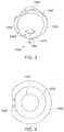
- FIG. 3 is a bottom perspective view of the elliptical lens 1000, further illustrating the proximal section 1060.
- the proximal section 1060 includes the input surface 1070.
- the input surface 1070 forms the surface of a cavity 1080 configured to receive at least partially a light source.
- the input surface 1070 comprises a central convex portion 1100 and a peripheral portion 1090.
- the convex portion 1100 exhibits a positive optical power in a range of about 50 D to about 300 D.
- FIG. 4 is a top view of the elliptical lens 1000, showing the distal section 1030 and the output surface 1020.
- FIG. 5 is a bottom view of the elliptical lens 1000, showing the proximal section 1060 having the input surface 1070, which is composed of the convex portion 1100 and the peripheral portion 1090.
- FIG. 6 shows a side view of the lens 1000.
- the proximal section 1060 and the distal section 1030 may be disposed about an optical axis 1150 of the lens body 1010.
- the output surface 1020 is substantially flat and is substantially orthogonal to the optical axis 1150.
- FIG. 7 shows a cross-sectional side view of the elliptical lens 1000 according to aspects of the present disclosure.
- the proximal section 1060 is shown to include the input surface 1070.
- the input surface 1070 defines a cavity 1080 configured to receive at least partially a light source, such as an LED (not shown).
- the input surface 1070 comprises a central convex portion 1100 and a peripheral portion 1090.
- the peripheral portion 1090 includes a proximal concave segment 1110 and a distal convex segment 1120.
- FIG. 8 is a bottom lateral view of the elliptical lens 1000, further showing the convex portion 1100 and the peripheral portion 1090 of the input surface 1070.
- the input surface 1070 can collect at least about 70%, or at least a about 80%, or at least about 90%, or at least about 95% (and preferably 100%) of the light emitted by a light source (such as an LED) that is optically coupled to the cavity formed by the input surface.
- a light source such as an LED
- the convex portion 1100 may be characterized by a positive optical power, for example in a range of about 50 D to about 300 D.
- the convex portion 1100 of the input surface converges the light entering the lens body via that portion such that at least a portion of the light (in many cases all the light) entering the lens body 1010 via the convex portion 1100 propagates to the output surface 1020 without striking the peripheral elliptical surface 1040.
- the peripheral portion 1090 of the input surface 1070 is shaped such that at least a portion of the light entering the lens body 1010 via the peripheral portion propagates to the elliptical peripheral surface 1040 to be reflected thereby.
- the peripheral portion 1090 may be shaped such that at least about 80%, or at least 90%, or at least 95% (and preferably 100%), of the light entering the lens body 1010 via the peripheral portion propagates to the peripheral surface 1040.
- the reflection of the light rays incident on the elliptical peripheral surface 1040 can result in mixing of those light rays, thereby improving color-over-angle uniformity of the light exiting the lens relative to the respective color-over-angle uniformity of the light emitted by the light source.
- the lens 1000 can improve the color-over-angle uniformity of the light it receives from a light source by at least about 20%, or by at least about 30%, or by at least about 40%, or by at least about 50%, or by at least about 60%.
- the lens 1000 may be formed of a transparent material that allows light to pass through.
- the lens 1000 may be composed of glass, plastic, or sapphire.
- any one or more of the lens body and the flange may be formed of a polymeric material.
- any one or more of the lens body and the flange may be formed of glass or silicone.
- suitable materials for forming the lens include, without limitation, polymethylmethacrylate (PMMA) and polycarbonate.
- the elliptical lens 1000 is configured to efficiently receive and transmit high output light to an illumination device.
- FIG. 9 shows an optical assembly 1200 including the lens 1000.
- the optical assembly 1200 further comprises a light guide 1210 coupled to the output surface 1020 of the lens 1000 for receiving light existing the lens.
- the light guide 1210 can be a single optical fiber, a bundle of optical fibers (e.g., a plurality of square or round-shaped optical fibers), a liquid light guide, a plurality of tapers made from glass or plastic to form a light guide, etc.
- the optical assembly 1200 further includes a light source 1220, such as an LED, which is placed at least partially within the cavity 1080 defined by the input surface 1070.
- the light source may be a high power LED (such as Luxeon III Model LXHL-LW3C) with a typical forward voltage of 3.7V and operating current at 700 mA. This device may be safely operated up to a current of 1 A with a corresponding typical forward voltage of 3.9V.
- the LED has a typical color temperature of 5500K.
- This LED has an emitting surface of approximately 1 mm ⁇ 1 mm, and is coated with a wavelength conversion phosphorus or fluorophore that emits a broadband continuum of visible white light between about 470-700 nm. This LED spreads the emitted light over a 160-degree angle (an angle at which 90% of the total illumination is captured).
- any LED may be used with the lens 1000, including for example LEDs emitting radiation in the ultraviolet, visible (e.g., 530 nm), near infrared, and infrared regions of the electromagnetic spectrum.
- the LED may have a power consumption of about 1 to 5 W.
- the light source may include a plurality of LEDs providing light at the same or different wavelengths.
- the elliptical lens 1000 is configured to collect the light emitted by the LED 1220 over a large angular spread and to converge that light so as it can be efficiently coupled to the light guide 1210 of an illumination device.
- the elliptical lens 1000 can receive light emitted by the LED that is characterized by a maximum angular spread of about 160 degrees and reduce that maximum angular spread to about 66 degrees for coupling to the light guide 1210.
- the numerical aperture associated with the output surface of the lens 1000 can be in a range of about 0.5 to about 0.9, e.g., about 0.66 or about 0.88.
- the peripheral elliptical surface 1040 of the lens 1000 is characterized by a proximal focal point 1230 (herein also referred to as the input focus or input focal point) and a distal focal point 1240 (herein also referred to as the distal focus, distal focal point, or the output focus).
- the proximal and distal focal points are positioned on the optical axis of the lens.
- the peripheral elliptical surface transfers at least a portion of the light emitted by the light source 1220 from the proximal focal point to the distal focal point.
- the proximal focal point is positioned within the input cavity and substantially at the light source 1220.
- the distal focal point 1240 is positioned external to the lens at a distance outside the output surface 1020 of the lens 1000.
- the position of the distal focal point 1240 is selected such that the light rays diverging from the distal focal point exhibit an angular spread across the input face of a light guide coupled to the lens that maximizes the coupling of the light into the light guide.
- the diverging beam can have an angular spread commensurate with an input numerical aperture of the light guide.
- the distance between the distal focal point 1240 and the output surface of the lens may be in the range of about 4 mm to about 6 mm, though other values can also be used depending, for example, on the lens size and/or particular application in which the lens is employed.
- the elliptical peripheral surface is shaped such that the distal focal point 1240 is positioned within the light guide proximate to its input surface so as to facilitate efficient coupling of the light exiting the lens into the light guide.
- the distal focal point 1240 may be positioned inside the lens (e.g., below the output surface 1020) or may be positioned at the output surface 1020 of the lens.
- the light guide 1210 has a flat face, substantially filling the entire emitting area of the output surface 1020 of the elliptical lens 1000.
- the light guide 1210 may be placed in contact with, or substantially close to, the output surface 1020 of the elliptical optic lens 1000.
- both the output surface 1020 and a surface of the light guide 1210 may be substantially flat, thereby allowing good contact therebetween.
- the flexibility of the light guide may also assist in achieving a higher degree of contact between the two surfaces.
- the substantially planar output surface 1020 of the elliptical lens 1000 is index matched with the input face of the light 1210 by disposing a refractive index matching material 1250 therebetween.
- the index matching material can be a liquid, a gel, an adhesive, or any other suitable material.
- the index matching material can minimize the reflection of the light at the interface between the output surface of the lens and the input face of the light guide, thereby enhancing the efficiency of the coupling of the light into the light guide.
- the elliptical lens may capture light emitted from the LED without direct contact with the LED.
- the LED may be disposed at a distance of less than about 3 mm or less than about 2 mm, e.g., at a distance of about 2.4 mm, from the convex portion of the lens' input surface.
- the input surface of the lens 1000 captures the light emitted by the LED 1220. A portion of that light enters the lens body via refraction at the peripheral portion 1090 of the input surface and another portion of that light enters the lens body via refraction at the central convex portion 1100 of the input surface.
- the light entering the lens body via the peripheral portion of the input surface propagates to the elliptical peripheral surface 1040 and is reflected thereby toward to the output focus 1240, which in this embodiment is located within a proximal portion of the light guide. As such, this reflected light exits the lens as a convergent bundle of rays to reach the output focus 1240 and then diverge beyond that point within the light guide.
- the output focus 1240 can be located internal to the lens such that the light rays reflected by the elliptical surface converge to arrive at the output focus 1240 and then diverge to reach the input face of the light guide.
- the location of the output face 1240 can be selected such that the rays reaching the input face of the light guide have a maximum angular spread corresponding to that of a solid angle subtended by the input face of the light pipe for effective coupling of the light into the light pipe.
- the central convex portion of the input surface provides a positive optical power, which results in the convergence of the light rays entering the lens body through that surface to a focal point (herein also referred to as the convergence point) typically located within the lens body, e.g., a small distance below the lens' output surface.
- the convex portion is configured such that its focal point (i.e., the point at which the light rays refracted by that portion converge) is external to the lens.
- the focal point of the convex portion may be within the proximal end of a light guide coupled to the lens, or external to both the lens and the light pipe such that the light rays diverging form the focal point to illuminate the input face of the light pipe would exhibit a maximum angular spread corresponding to that of a solid angle subtended by the input face of the light guide.
- the focal point of the convex portion can be substantially coincident with the distal focal point of the elliptical peripheral surface.
- the elliptical lens may be embedded and easily adapted for use with different types of illumination devices.
- the elliptical optic lens may be embedded within medical or industrial endoscopes, video cameras, retractors, speculums, surgical headlights and other devices requiring high intensity, high quality light.
- the elliptical lens may be removably and replaceably contained within an illumination device.
- the elliptical lens captures and transmits the LED light without relying on mirrors, other lenses, or multiple LEDs.
- the lack of such additional optical components (such as additional optics between the LED light source and the lens) simplifies the mechanical design and volume occupied by the lens for easier incorporation into a variety of illumination devices.
- the LED light source is very efficient in converting electrical energy into light, allowing small batteries to be used to power the LED, thereby permitting the illumination device to operate without connection to an external light source. Accordingly, optical assemblies disclosed herein may operate for a considerable length of time without the need for battery replacement or recharging, and without making the illumination device cumbersome or unwieldy. As a result, illumination devices in accordance with the presence invention can be small and compact while providing the desired illumination strength.
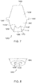
- FIG. 10 schematically depicts a lens 1500 according to another embodiment, which includes a lens body 1500a disposed about an optical axis (OA) and having an input surface 1501, an output surface 1502 and a peripheral surface 1503.
- OA optical axis
- the input surface 1501 is composed of a central convex portion 1501a and a peripheral portion 1501b, which collectively form a cavity for at least partially receiving a light source.
- the peripheral portion 1501b includes a proximal concave segment (A) and a distal convex segment (B).
- a collar 1504 disposed in proximity of the output surface 1502 partially encircles the lens body. Similar to the previous embodiment, the collar 1504 facilitates positioning the lens within a light illumination device.
- the peripheral surface 1503 of the lens is in the form of a truncated ellipse having an input focus f1 and an output focus f2.
- the input focus f1 is positioned within the input cavity and the output focus f2 is positioned external to the lens body at a distance from the output surface, e.g., at a distance in a range of about 4 mm to about 6 mm from the output surface.
- the output focus f2 can be positioned within the lens body, e.g., at a small distance below the output surface, or at the output surface.
- the elliptical peripheral surface 1503 can extend from the input surface of the lens to its output surface.
- a proximal portion 1503a of the peripheral surface of the lens can have an elliptical shape (e.g., a portion extending from the input surface to the collar 1504), and a distal portion 1503b of the peripheral surface can have a different shape (e.g., a truncated conical shape)
- the input surface 1501 collects the light emitted by a light source coupled to the lens. A portion of the light enters the lens body via the central convex portion of the input surface and propagates to the output surface, typically without striking the peripheral elliptical surface. Another portion of the received light enters the lens body via the peripheral portion of the input surface and propagates to the peripheral elliptical surface to be reflected thereby toward to the output surface of the lens.
- the lens 1500 can be formed of a variety of materials, such as a variety of polymeric materials.
- suitable materials include polymethylmethacrylate (PMMA), polycarbonate, high density polyethylene, glass, etc.
- the lens 1500 can be used in an optical assembly, such as the optical assembly discussed above in connection with FIG. 9 . Further, similar to the previous embodiment, the lens 1500 can be embedded in a variety of different illumination devices, such as endoscopic systems.
- FIG. 12 schematically depicts an optical assembly 1600, which includes the above lens 1500 optically coupled to a light guide 1700.
- the input face 1601 of the light pipe is positioned at a distance (d) relative to the output surface 1502 of the lens.
- the output surface of the lens is not in contact with the input face of the light pipe. Nonetheless, the output surface of the lens and the input face of the light pipe are sufficiently close to allow efficient coupling of the light exiting the lens into the light guide.
- a spacer (not shown) can be used to fixedly hold the light guide a desired distance relative to the output surface 1502 of the lens.
- the output focus of the peripheral elliptical surface of the lens be located in the gap separating the output surface of the lens from the input face of the light pipe.
- a lens according to the present teachings can have a variety of different sizes.
- the diameter of the lens output surface and its shape can be configured to efficient coupling of the lens to a light guide.
- the output surface of the lens can have a circular shape with a diameter in a range of about 1 mm to about 10 mm, though other sizes can also be employed.
- the lenses according to the present teachings can be fabricated using known manufacturing techniques, such as molding, etc.
Description
- The present disclosure relates generally to optical lenses and more specifically to elliptical optical lenses that capture and transmit light with high efficiency.
- Many devices that operate in small, closed areas, require a light source to operate. For example, laparoscopic and endoscopic procedures are conducted through small incisions in the skin or natural body orifices. In order to operate or view an internal area, medical professionals use endoscopes that have small, elongated distal portions that fit within these small openings but are long enough to reach the internal areas within the body. These instruments need to provide precise and accurate movement in order to reach areas within the body that are difficult to access. The distal working ends of the endoscopes usually contain a small camera that allows a medical professional to view the internal area within the body during the procedure. This camera and the working end of the endoscope must have adequate remotely controlled illumination to permit the medical professional to view the internal area. In some endoscopes, a camera positioned outside the patient's body can receive, via a light guide, radiation reflected from an illuminated internal area and form an image of that area for viewing by a medical professional.
- Conventional light sources for devices such as endoscopes are burdensome, very inefficient in convening electrical power to light, produce large amounts of heat that must be dissipated, and require that the devices be connected to external light sources, limiting the range of motion. For example, incandescent lamps produce light by passing current through a highly flexible, elongated, tungsten filament, causing the entire filament to radiate light in proportion to its temperature. Arc lamps produce light by creating plasma between two electrodes within a sealed bulb. Both types of lamps produce too much heat and must be connected to large external light sources
- Light sources that produce much less heat, such as light emitting diodes (LEDs), usually do not produce enough illumination to effectively assist a device such as an endoscope. One approach to increase this low level of light is by coupling multiple light emitting diodes (LEDs) to long, flexible fiber optic light guides. Many LEDs must be used due to low light output emitted by LEDs into the optical fiber. Another approach for bolstering the low light output between LEDs and optical fibers is to utilize various combinations of lenses, mirrors, or prisms in order to collect and focus LED-generated light into the optical fiber. A further approach for bolstering the low light output is to couple multiple optical fibers to separate LEDs, so as to produce a greater cumulative light output.
- However, each of these conventional approaches can result in ineffective illumination for most lighting applications. For example, light loss due to inefficient coupling between the LED and the optical fiber can limit the amount of light transmitted between them. In addition, non-rigid, non-mechanical attempts to increase the efficiency between LEDs and optical fibers can prevent interchangeability of an illumination device and necessitate a complex alignment procedure between the LED and the optical fiber.
- Accordingly, there is a need for optical lenses that efficiently capture and focus light for transmission to a light guide.
-
US 2004/0218858 A1 describes an apparatus for focusing light generated from an extended light source into a beam able to be coupled into a light guide. The apparatus comprises a solid conic body having a longitudinal axis for receiving the light and reflecting, through total internal reflection, a first portion of the light to an input end of the light guide. A lens is disposed within the solid conic body for refracting and focusing a second portion of the light from the extended light source to the input end of the light guide. - According to one aspect, a lens is disclosed, which comprises a lens body comprising a proximal section having at least one input surface for receiving light from a light source and a distal section having at least one output surface through which light exits the lens body. The proximal section further comprises a substantially elliptical peripheral surface receiving at least a portion of the light entering the lens body via said at least one input surface and directing at least some of said received light via total internal reflection to said distal section such that at least a portion of the light directed to the distal section exits the lens body through said at least one output surface.
- In some embodiments, the peripheral elliptical surface may be characterized by a proximal focal point and a distal focal point and may be shaped such that said distal focal point is positioned outside of said distal section of the lens body.
- In some embodiments, said distal focal point may be positioned at a distance in a range of about 4 mm to about 6 mm relative to the output surface. In some embodiments, the distal focal point may be positioned inside said lens body. In some embodiments, the distal focal point may be positioned at a distance in a range of about 4 mm to about 6 mm below said output surface. In some embodiments, the proximal focal point of the elliptical surface may be positioned at or in proximity of the light source such that the elliptical surface transfers at least a portion of the light emitted by the light source from the proximal focal point to the distal focal point.
- The input surface of the lens comprises a central convex portion and a peripheral portion surrounding said central convex portion.
- In some embodiments, the input surface of the lens can form a surface of a cavity configured to receive at least partially the light source. In some embodiments, the proximal focal point of the elliptical surface may be disposed within said cavity.
- In some embodiments, the peripheral portion of the input surface may be shaped such that at least a portion of the light entering the lens body via said peripheral portion propagates to the peripheral elliptical surface to be reflected thereby. In some embodiments, the peripheral portion of the input surface may be shaped such that at least about 80% of the light entering the lens body via the peripheral portion propagates to the peripheral surface of the lens body.
- The convex portion of the input surface is characterized by a positive optical power in a range of about 50D to about 300 D. In some embodiments, at least a portion of the light entering the lens body via the convex portion propagates to the output surface. In some embodiments, the convex portion may be configured such that the light entering the lens body via the convex portion propagates to the output surface without striking the elliptical peripheral surface. In some embodiments, the peripheral portion of the input surface may comprise a proximal concave segment and distal convex segment.
- In some embodiments, the input surface may be configured to capture at least about 70%, or at least about 80%, or at least about 90%, or at least about 95% (and preferably 100%) of the light emitted by the light source. In some embodiments, the input surface may be configured to capture at least about 90% of the light emitted by said light source.
- In some embodiments, the proximal section and said distal section may be disposed about an optical axis of the lens body. In some embodiments, the output surface may be substantially flat. In some embodiments, the output surface may be substantially orthogonal to said optical axis.
- In some embodiments, the lens may further comprise a collar at least partially surrounding the lens body. In some embodiments, the collar may be disposed at a boundary between said proximal section and said distal section. In some embodiments, the proximal and distal sections may form a unitary structure. In some embodiments, the proximal and distal sections and the collar may form a unitary structure.
- In some embodiments, the lens body and collar may be formed of a polymeric material. In some embodiments, said polymeric material may be any of polycarbonate, polymethylmethacrylate (PMMA), and high density polyethylene. In some embodiments, any of said lens body and said collar may be formed of any of glass and silicone.
- According to another aspect, there is disclosed an optical assembly comprising a lens having a lens body comprising a proximal section having at least one input surface for receiving light from a light source, and a distal section having at least one output surface through which light exits the lens body. The optical assembly further comprises a light guide optically coupled to said output surface of the lens body for receiving at least a portion of the light exiting the lens. The proximal section further comprises a substantially elliptical peripheral surface receiving at least a portion of the light entering the lens body via said at least one input surface and directing at least some of the received light via total internal reflection to said distal section such that at least a portion of the light directed to the distal section exits the lens body through said at least one output surface. In some embodiments, the light guide may be attached to the output surface of the lens. In some embodiments, the peripheral elliptical surface may be characterized by a proximal focal point and a distal focal point and may be shaped such that the distal focal point is positioned outside of said distal section of the lens body.
- In some embodiments, said distal focal point may be positioned at a distance in a range of about 4 mm to about 6 mm relative to said output surface. In some embodiments, the proximal focal point of said elliptical surface may be positioned substantially at or in proximity of the light source such that the elliptical surface transfers at least a portion of light emitted by the light source from the proximal focal point to the distal focal point. In some embodiments, the input surface may comprise a central convex portion and a peripheral portion surrounding said central convex portion. In some embodiments, the peripheral portion of the input surface may be shaped such that at least a portion of the light entering the lens body via said peripheral portion propagates to the peripheral elliptical surface to be reflected thereby. In some embodiments, the convex portion may be characterized by a positive optical power in a range of about 50 D to about 300 D. In some embodiments, the peripheral portion of the input surface may comprise a proximal concave segment and distal convex segment.
- In some embodiments of the above optical assembly, the input surface may be configured to capture at least about 70%, or at least about 80%, or at least about 90% (and preferably 100%) of the light emitted by said light source. In some embodiments, said lens may further comprise a collar encircling at least partially the lens body. In some embodiments, the lens body and said collar may be formed as a unitary structure.
- According to another aspect, there is disclosed a lens comprising a lens body, which includes an input surface for receiving light from a light source, an output surface through which light exits the lens body, and an elliptical peripheral surface for receiving at least a portion for the light entering the lens body via said input surface and directing said received light via total internal reflection to said output surface. In some embodiments, the lens may further comprise a collar at least partially encircling the lens body.
- In some embodiments, the elliptical surface may be characterized by an input focus and output focus. In some embodiments, the input focus may be positioned at or in proximity of the light source. In some embodiments, the output focus may be positioned outside of the lens body. In some embodiments, the output focus may be positioned within the lens body. In some embodiments, the input surface may comprise a convex central portion and a peripheral portion surrounding said central portion.
- According to another aspect, there is disclosed an optical assembly, comprising a lens having a lens body comprising an input surface for receiving light from a light source, an output surface through which the light exits the lens body, and an elliptical peripheral surface for receiving at least a portion for the light entering the lens body via said input surface and directing said received light via total internal reflection to said output surface. The optical assembly further comprises a light guide optically coupled to the output surface of the lens body for receiving at least a portion of the light exiting the lens. In some embodiments, said lens further comprises a collar at least partially encircling said lens body.
- The invention is defined in the appended claims. Aspects, embodiments and examples disclosed herein which do not fall within the scope of the appended claims do not form part of the invention, and are merely provided for illustrative purposes.
-
-
FIG. 1 is a top perspective view of one embodiment of an elliptical optic LED lens according to aspects of the present disclosure; -
FIG. 2 is another top perspective view of the elliptical lens ofFIG. 1 according to aspects of the present disclosure; -
FIG. 3 is a bottom perspective view of the elliptical lens ofFIG. 1 according to aspects of the present disclosure; -
FIG. 4 is a top view of the elliptical lens ofFIG. 1 according to aspects of the present disclosure; -
FIG. 5 is a bottom view of the elliptical lens ofFIG. 1 according to aspects of the present disclosure; -
FIG. 6 is a side view of the elliptical lens ofFIG. 1 according to aspects of the present disclosure; -
FIG. 7 is a side cross-sectional view of the elliptical lens ofFIG. 1 according to aspects of the present disclosure; -
FIG. 8 is a bottom lateral cross-sectional view of the elliptical lens ofFIG. 1 according to aspects of the present disclosure; -
FIG. 9 shows propagation of light through an optical assembly including the elliptical lens ofFIG. 1 according to aspects of the present disclosure; -
FIG. 10 is a schematic perspective view of a lens according to another embodiment of the present teachings; -
FIG. 11 is a schematic cross-sectional view of the lens depicted inFIG. 10 ; and -
FIG. 12 is a schematic cross-sectional view of an optical assembly according to an embodiment in which a light guide is optical coupled to an output of a lens according to the present teachings. - It is to be understood that the invention is not limited in its application to the details of construction and to the arrangements of the components set forth in the following description or illustrated in the drawings. The invention is capable of other embodiments and of being practiced and carried out in various ways. Also, it is to be understood that the phraseology and terminology employed herein are for the purpose of the description and should not be regarded as limiting.
- The term "optical power" is used herein consistent with its common meaning in the art to refer to the degree to which an optical component or surface converges or diverges incident light and is equal to the reciprocal of the focal length of the component of the surface.
- The term "numerical aperture" is used herein consistent with its common meaning in the art to refer to a dimensionless number that characterizes the range of angles over which an optical component or system can emit or accept light.
- The term "elliptical surface" or similar terms as used herein refer to a surface that is shaped as a section of an ellipse. In other words, an elliptical surface is in the form of a truncated ellipse.
- The term "about" as used herein is intended to indicate a variation of at most 10% around a numerical value.
- The term "substantially" is defined herein as at least close to (and may include) a given value or state, as understood by a person of ordinary skill in the art. In one embodiment, the term "substantially" refers to ranges within 10%, preferably within 5%, more preferably within 1%, and most preferably within 0.1% of the given value or state being specified.
- According to aspects of the present disclosure, there is disclosed embodiments of an elliptical lens configured to capture most of the light emitted by a light source such as an LED light source, and to converge the light onto an output surface for efficient transmission to a light guide.
- Embodiments of the lens disclosed herein may be easily adapted for use with different types of illumination devices, such as different endoscopes. In many embodiments, optical assemblies including an LED light source and an elliptical lens as disclosed herein, can provide higher illumination near the distal working end of an illumination device, with less power and less heat produced. Small batteries may be used to power the LED light source, permitting the illumination device to be compact and to operate without connection to an external light source.
-
FIGS. 1, 2 and3 show perspective views of one embodiment of a lens 1000 (herein also referred to as an elliptical lens) according to aspects of the present disclosure. Thelens 1000 comprises alens body 1010 disposed about an optical axis OA and having adistal section 1030 and aproximal section 1060. Theproximal section 1060 includes aninput surface 1070 for receiving light from a light source. In some embodiments, theproximal section 1060 may include a plurality of input surfaces. Thedistal section 1030 includes anoutput surface 1020, through which light exits thelens body 1010 and aperipheral portion 1019 that has a truncated conical shape in this embodiment, though other shapes can also be employed. In some embodiments, thedistal section 1030 may include a plurality of output surfaces. Theelliptical lens 1000 is configured to efficiently capture light emitted, for example, by an LED light source, and to transfer it onto a light guide coupled to the output surface 1020 (as shown and discussed with reference toFIG. 9 ). - The
proximal section 1060 further comprises a substantially ellipticalperipheral surface 1040, which is configured to receive at least a portion of the light entering thelens body 1010 via theinput surface 1070. Theelliptical surface 1040 is configured to direct at least a portion of the received light via total internal reflection to thedistal section 1030, such that at least a portion of the light directed to the distal section exits thelens body 1010 through theoutput surface 1020. In some embodiments, theelliptical surface 1040 reflects at least about 80%, or at least about 90% (and preferably 100%) of the light incident thereon. - The
lens 1000 can include a collar 1050 (herein also referred to as flange) coupled to thelens body 1010, as shown for example inFIG. 1 . The flange may be positioned, for example, at a central section of the lens that has a wider diameter, and may be configured to facilitate holding thelens 1000 within an illumination device. In this embodiment, theflange 1050 is disposed at a boundary between theproximal section 1060 and thedistal section 1030 of the lens. - In some embodiments, the
proximal section 1060 and thedistal section 1030 may form a unitary structure. In other embodiments, theproximal section 1060, thedistal section 1030 and theflange 1050 may form a unitary structure. - The
distal portion 1030 of theelliptical lens 1000 may be cone-shaped, tapering from a wider central diameter to a substantiallyplanar output surface 1020 having a smaller diameter. -
FIG. 3 is a bottom perspective view of theelliptical lens 1000, further illustrating theproximal section 1060. Theproximal section 1060 includes theinput surface 1070. In this embodiment, theinput surface 1070 forms the surface of acavity 1080 configured to receive at least partially a light source. Theinput surface 1070 comprises a centralconvex portion 1100 and aperipheral portion 1090. - In some embodiment the
convex portion 1100 exhibits a positive optical power in a range of about 50 D to about 300 D. -
FIG. 4 is a top view of theelliptical lens 1000, showing thedistal section 1030 and theoutput surface 1020.FIG. 5 is a bottom view of theelliptical lens 1000, showing theproximal section 1060 having theinput surface 1070, which is composed of theconvex portion 1100 and theperipheral portion 1090. -
FIG. 6 shows a side view of thelens 1000. Theproximal section 1060 and thedistal section 1030 may be disposed about anoptical axis 1150 of thelens body 1010. In this embodiment, theoutput surface 1020 is substantially flat and is substantially orthogonal to theoptical axis 1150. -
FIG. 7 shows a cross-sectional side view of theelliptical lens 1000 according to aspects of the present disclosure. InFIG. 7 , theproximal section 1060 is shown to include theinput surface 1070. Theinput surface 1070 defines acavity 1080 configured to receive at least partially a light source, such as an LED (not shown). As noted above, theinput surface 1070 comprises a centralconvex portion 1100 and aperipheral portion 1090. In this embodiment, theperipheral portion 1090 includes a proximalconcave segment 1110 and a distalconvex segment 1120.FIG. 8 is a bottom lateral view of theelliptical lens 1000, further showing theconvex portion 1100 and theperipheral portion 1090 of theinput surface 1070. - In some embodiments, the
input surface 1070 can collect at least about 70%, or at least a about 80%, or at least about 90%, or at least about 95% (and preferably 100%) of the light emitted by a light source (such as an LED) that is optically coupled to the cavity formed by the input surface. - As noted above, in some embodiments, the
convex portion 1100 may be characterized by a positive optical power, for example in a range of about 50 D to about 300 D. In various embodiments, theconvex portion 1100 of the input surface converges the light entering the lens body via that portion such that at least a portion of the light (in many cases all the light) entering thelens body 1010 via theconvex portion 1100 propagates to theoutput surface 1020 without striking the peripheralelliptical surface 1040. - The
peripheral portion 1090 of theinput surface 1070 is shaped such that at least a portion of the light entering thelens body 1010 via the peripheral portion propagates to the ellipticalperipheral surface 1040 to be reflected thereby. For example, in one embodiment, theperipheral portion 1090 may be shaped such that at least about 80%, or at least 90%, or at least 95% (and preferably 100%), of the light entering thelens body 1010 via the peripheral portion propagates to theperipheral surface 1040. - In some embodiments, the reflection of the light rays incident on the elliptical
peripheral surface 1040 can result in mixing of those light rays, thereby improving color-over-angle uniformity of the light exiting the lens relative to the respective color-over-angle uniformity of the light emitted by the light source. By way of example, in some embodiments, thelens 1000 can improve the color-over-angle uniformity of the light it receives from a light source by at least about 20%, or by at least about 30%, or by at least about 40%, or by at least about 50%, or by at least about 60%. - In various embodiments, the
lens 1000 may be formed of a transparent material that allows light to pass through. For example, thelens 1000 may be composed of glass, plastic, or sapphire. In some embodiments, any one or more of the lens body and the flange may be formed of a polymeric material. In some embodiments, any one or more of the lens body and the flange may be formed of glass or silicone. Some suitable materials for forming the lens include, without limitation, polymethylmethacrylate (PMMA) and polycarbonate. - The
elliptical lens 1000 is configured to efficiently receive and transmit high output light to an illumination device. By way of example,FIG. 9 shows anoptical assembly 1200 including thelens 1000. Theoptical assembly 1200 further comprises alight guide 1210 coupled to theoutput surface 1020 of thelens 1000 for receiving light existing the lens. For example, thelight guide 1210 can be a single optical fiber, a bundle of optical fibers (e.g., a plurality of square or round-shaped optical fibers), a liquid light guide, a plurality of tapers made from glass or plastic to form a light guide, etc. - The
optical assembly 1200 further includes alight source 1220, such as an LED, which is placed at least partially within thecavity 1080 defined by theinput surface 1070. In one embodiment, the light source may be a high power LED (such as Luxeon III Model LXHL-LW3C) with a typical forward voltage of 3.7V and operating current at 700 mA. This device may be safely operated up to a current of 1 A with a corresponding typical forward voltage of 3.9V. The LED has a typical color temperature of 5500K. - This LED has an emitting surface of approximately 1 mm × 1 mm, and is coated with a wavelength conversion phosphorus or fluorophore that emits a broadband continuum of visible white light between about 470-700 nm. This LED spreads the emitted light over a 160-degree angle (an angle at which 90% of the total illumination is captured). In various embodiments, any LED may be used with the
lens 1000, including for example LEDs emitting radiation in the ultraviolet, visible (e.g., 530 nm), near infrared, and infrared regions of the electromagnetic spectrum. In some embodiments, the LED may have a power consumption of about 1 to 5 W. In some embodiments, the light source may include a plurality of LEDs providing light at the same or different wavelengths. - The
elliptical lens 1000 is configured to collect the light emitted by theLED 1220 over a large angular spread and to converge that light so as it can be efficiently coupled to thelight guide 1210 of an illumination device. For example, theelliptical lens 1000 can receive light emitted by the LED that is characterized by a maximum angular spread of about 160 degrees and reduce that maximum angular spread to about 66 degrees for coupling to thelight guide 1210. In some such embodiments, the numerical aperture associated with the output surface of thelens 1000 can be in a range of about 0.5 to about 0.9, e.g., about 0.66 or about 0.88. - With continued reference to
FIG. 9 , the peripheralelliptical surface 1040 of thelens 1000 is characterized by a proximal focal point 1230 (herein also referred to as the input focus or input focal point) and a distal focal point 1240 (herein also referred to as the distal focus, distal focal point, or the output focus). In this embodiment, the proximal and distal focal points are positioned on the optical axis of the lens. - The peripheral elliptical surface transfers at least a portion of the light emitted by the
light source 1220 from the proximal focal point to the distal focal point. In this embodiment, the proximal focal point is positioned within the input cavity and substantially at thelight source 1220. Further, in this embodiment, the distalfocal point 1240 is positioned external to the lens at a distance outside theoutput surface 1020 of thelens 1000. In some embodiments, the position of the distalfocal point 1240 is selected such that the light rays diverging from the distal focal point exhibit an angular spread across the input face of a light guide coupled to the lens that maximizes the coupling of the light into the light guide. For example, the diverging beam can have an angular spread commensurate with an input numerical aperture of the light guide. For example, the distance between the distalfocal point 1240 and the output surface of the lens may be in the range of about 4 mm to about 6 mm, though other values can also be used depending, for example, on the lens size and/or particular application in which the lens is employed. In this embodiment, the elliptical peripheral surface is shaped such that the distalfocal point 1240 is positioned within the light guide proximate to its input surface so as to facilitate efficient coupling of the light exiting the lens into the light guide. In other embodiments, the distalfocal point 1240 may be positioned inside the lens (e.g., below the output surface 1020) or may be positioned at theoutput surface 1020 of the lens. - In this embodiment, the
light guide 1210 has a flat face, substantially filling the entire emitting area of theoutput surface 1020 of theelliptical lens 1000. Thelight guide 1210 may be placed in contact with, or substantially close to, theoutput surface 1020 of theelliptical optic lens 1000. In some embodiments, both theoutput surface 1020 and a surface of thelight guide 1210 may be substantially flat, thereby allowing good contact therebetween. The flexibility of the light guide may also assist in achieving a higher degree of contact between the two surfaces. In this embodiment, the substantiallyplanar output surface 1020 of theelliptical lens 1000 is index matched with the input face of the light 1210 by disposing a refractiveindex matching material 1250 therebetween. By way of example, the index matching material can be a liquid, a gel, an adhesive, or any other suitable material. The index matching material can minimize the reflection of the light at the interface between the output surface of the lens and the input face of the light guide, thereby enhancing the efficiency of the coupling of the light into the light guide. - With continued reference to
FIG. 9 , in some embodiments, the elliptical lens may capture light emitted from the LED without direct contact with the LED. By way of example, the LED may be disposed at a distance of less than about 3 mm or less than about 2 mm, e.g., at a distance of about 2.4 mm, from the convex portion of the lens' input surface. - In use, the input surface of the
lens 1000 captures the light emitted by theLED 1220. A portion of that light enters the lens body via refraction at theperipheral portion 1090 of the input surface and another portion of that light enters the lens body via refraction at the centralconvex portion 1100 of the input surface. The light entering the lens body via the peripheral portion of the input surface propagates to the ellipticalperipheral surface 1040 and is reflected thereby toward to theoutput focus 1240, which in this embodiment is located within a proximal portion of the light guide. As such, this reflected light exits the lens as a convergent bundle of rays to reach theoutput focus 1240 and then diverge beyond that point within the light guide. In some other embodiments, theoutput focus 1240 can be located internal to the lens such that the light rays reflected by the elliptical surface converge to arrive at theoutput focus 1240 and then diverge to reach the input face of the light guide. As noted above, in some such embodiments, the location of theoutput face 1240 can be selected such that the rays reaching the input face of the light guide have a maximum angular spread corresponding to that of a solid angle subtended by the input face of the light pipe for effective coupling of the light into the light pipe. - The portion of the light rays entering the lens body via refraction at the central
convex portion 1100 of the input surface propagates to through the lens body without striking theperipheral surface 1040 to reach theoutput surface 1020 through which it exits the lens. As noted above, in this embodiment the central convex portion of the input surface provides a positive optical power, which results in the convergence of the light rays entering the lens body through that surface to a focal point (herein also referred to as the convergence point) typically located within the lens body, e.g., a small distance below the lens' output surface. In some other embodiments, the convex portion is configured such that its focal point (i.e., the point at which the light rays refracted by that portion converge) is external to the lens. By way of example, the focal point of the convex portion may be within the proximal end of a light guide coupled to the lens, or external to both the lens and the light pipe such that the light rays diverging form the focal point to illuminate the input face of the light pipe would exhibit a maximum angular spread corresponding to that of a solid angle subtended by the input face of the light guide. By way of example, in some such embodiments, the focal point of the convex portion can be substantially coincident with the distal focal point of the elliptical peripheral surface. - The elliptical lens may be embedded and easily adapted for use with different types of illumination devices. In various embodiments, the elliptical optic lens may be embedded within medical or industrial endoscopes, video cameras, retractors, speculums, surgical headlights and other devices requiring high intensity, high quality light. In some embodiments, the elliptical lens may be removably and replaceably contained within an illumination device.
- In various embodiments, the elliptical lens captures and transmits the LED light without relying on mirrors, other lenses, or multiple LEDs. The lack of such additional optical components (such as additional optics between the LED light source and the lens) simplifies the mechanical design and volume occupied by the lens for easier incorporation into a variety of illumination devices.
- The LED light source is very efficient in converting electrical energy into light, allowing small batteries to be used to power the LED, thereby permitting the illumination device to operate without connection to an external light source. Accordingly, optical assemblies disclosed herein may operate for a considerable length of time without the need for battery replacement or recharging, and without making the illumination device cumbersome or unwieldy. As a result, illumination devices in accordance with the presence invention can be small and compact while providing the desired illumination strength.
-
FIG. 10 schematically depicts alens 1500 according to another embodiment, which includes alens body 1500a disposed about an optical axis (OA) and having aninput surface 1501, anoutput surface 1502 and aperipheral surface 1503. - Similar to the previous embodiment, the
input surface 1501 is composed of a centralconvex portion 1501a and aperipheral portion 1501b, which collectively form a cavity for at least partially receiving a light source. In this embodiment, theperipheral portion 1501b includes a proximal concave segment (A) and a distal convex segment (B). Acollar 1504 disposed in proximity of theoutput surface 1502 partially encircles the lens body. Similar to the previous embodiment, thecollar 1504 facilitates positioning the lens within a light illumination device. - Further, similar to the previous embodiment, the
peripheral surface 1503 of the lens is in the form of a truncated ellipse having an input focus f1 and an output focus f2. In this embodiment, the input focus f1 is positioned within the input cavity and the output focus f2 is positioned external to the lens body at a distance from the output surface, e.g., at a distance in a range of about 4 mm to about 6 mm from the output surface. In other embodiments, the output focus f2 can be positioned within the lens body, e.g., at a small distance below the output surface, or at the output surface. - In some embodiments, the elliptical
peripheral surface 1503 can extend from the input surface of the lens to its output surface. In some other embodiments, aproximal portion 1503a of the peripheral surface of the lens can have an elliptical shape (e.g., a portion extending from the input surface to the collar 1504), and adistal portion 1503b of the peripheral surface can have a different shape (e.g., a truncated conical shape) - In use, the
input surface 1501 collects the light emitted by a light source coupled to the lens. A portion of the light enters the lens body via the central convex portion of the input surface and propagates to the output surface, typically without striking the peripheral elliptical surface. Another portion of the received light enters the lens body via the peripheral portion of the input surface and propagates to the peripheral elliptical surface to be reflected thereby toward to the output surface of the lens. - The
lens 1500 can be formed of a variety of materials, such as a variety of polymeric materials. Some examples of suitable materials include polymethylmethacrylate (PMMA), polycarbonate, high density polyethylene, glass, etc. - The
lens 1500 can be used in an optical assembly, such as the optical assembly discussed above in connection withFIG. 9 . Further, similar to the previous embodiment, thelens 1500 can be embedded in a variety of different illumination devices, such as endoscopic systems. -
FIG. 12 schematically depicts anoptical assembly 1600, which includes theabove lens 1500 optically coupled to alight guide 1700. In this embodiment, the input face 1601 of the light pipe is positioned at a distance (d) relative to theoutput surface 1502 of the lens. In other words, in this embodiment, the output surface of the lens is not in contact with the input face of the light pipe. Nonetheless, the output surface of the lens and the input face of the light pipe are sufficiently close to allow efficient coupling of the light exiting the lens into the light guide. In some embodiments, a spacer (not shown) can be used to fixedly hold the light guide a desired distance relative to theoutput surface 1502 of the lens. In some such embodiments, the output focus of the peripheral elliptical surface of the lens be located in the gap separating the output surface of the lens from the input face of the light pipe. - A lens according to the present teachings, such as those described above, can have a variety of different sizes. For example the diameter of the lens output surface and its shape can be configured to efficient coupling of the lens to a light guide. By way of example, in some embodiments, such as those discussed above, the output surface of the lens can have a circular shape with a diameter in a range of about 1 mm to about 10 mm, though other sizes can also be employed. Further, the lenses according to the present teachings can be fabricated using known manufacturing techniques, such as molding, etc.
Claims (12)
- An optical assembly (1200), comprising:a lens (1000) having a lens body (1010) comprising a proximal section having at least one input surface (1070) for receiving light from a light source (1220) and a distal section (1030) having at least one output surface (1020) through which light exits the lens body (1010),a light guide (1210) optically coupled to the output surface (1020) of the lens body (1010) for receiving at least a portion of the light exiting the lens (1000),wherein the proximal section (1060) further comprises:a substantially elliptical peripheral surface (1040) receiving at least a portion of the light entering the lens body (1010) via the at least one input surface (1070) and directing at least some of the received light via total internal reflection to the distal section (1030) such that at least a portion of the light directed to the distal section (1030) exits the lens body (1010) through the at least one output surface (1020),characterized in thatthe at least one input surface (1070) comprises a central convex portion (1100) and a peripheral portion (1090) surrounding the central convex portion (1100), andthe central convex portion (1100) is characterized by a positive optical power in a range of about 50 D to about 300 D.
- The optical assembly of claim 1, wherein the at least one output surface (1020) is substantially flat and being substantially orthogonal to an optical axis (OA).
- The optical assembly of claim 1, wherein the substantially elliptical peripheral surface (1040) is characterized by a proximal focal point (1230) and a distal focal point (1240) and is shaped such that the distal focal point (1240) is positioned outside of the distal section (1030) of the lens body (1010).
- The optical assembly of claim 3, wherein the distal focal point (1240) is positioned at a distance in a range of about 4 mm to about 6 mm relative to the output surface (1020).
- The optical assembly of claim 3, wherein the proximal focal point (1230) of the elliptical surface (1040) is positioned substantially at or in proximity of the light source (1220) such that the elliptical surface (1040) transfers at least a portion of light emitted by the light source (1220) from the proximal focal point (1230) to the distal focal point (1240).
- The optical assembly of claim 1, wherein the peripheral portion (1090) of the input surface (1070) is shaped such that at least a portion of the light entering the lens body (1010) via the peripheral portion (1090) propagates to the peripheral elliptical surface (1040) to be reflected thereby.
- The optical assembly of claim 1, wherein the peripheral portion (1090) of the input surface (1070) comprises a proximal concave segment (1110) and distal convex segment (1120).
- The optical assembly of claim 1, wherein the input surface (1070) is configured to capture at least about 80% of the light emitted by the light source (1220).
- The optical assembly of claim 1, wherein the lens (1000) further comprises a flange (1050) encircling the lens body (1010).
- The optical assembly of claim 9, wherein the lens body (1010) and the flange (1050) are formed as a unitary structure.
- The optical assembly of claim 1, wherein said central convex portion (1100) and said peripheral portion (1090) surrounding the central convex portion (1100) of the input surface (1070) collectively form a cavity (1080) for at least partially receiving the light source (1220).
- The optical assembly of claim 11, wherein the substantially elliptical peripheral surface (1040) is characterized by a proximal focal point (1230) and a distal focal point (1240), wherein the proximal focal point (1230) is within the cavity (1080) and the distal focal point (1240) is at a distance from the at least one output surface (1020) such that light rays diverging from the distal focal point (1240) exhibit an angular spread commensurate with a numerical aperture of the light guide (1210).
Priority Applications (1)
| Application Number | Priority Date | Filing Date | Title |
|---|---|---|---|
| EP21164168.3A EP3858220B1 (en) | 2015-10-28 | 2016-10-28 | Elliptical optical lens for high output led |
Applications Claiming Priority (4)
| Application Number | Priority Date | Filing Date | Title |
|---|---|---|---|
| US201562247451P | 2015-10-28 | 2015-10-28 | |
| US201562247454P | 2015-10-28 | 2015-10-28 | |
| US201562247456P | 2015-10-28 | 2015-10-28 | |
| PCT/US2016/059361 WO2017075378A1 (en) | 2015-10-28 | 2016-10-28 | Elliptical optical lens for high output led |
Related Child Applications (1)
| Application Number | Title | Priority Date | Filing Date |
|---|---|---|---|
| EP21164168.3A Division EP3858220B1 (en) | 2015-10-28 | 2016-10-28 | Elliptical optical lens for high output led |
Publications (2)
| Publication Number | Publication Date |
|---|---|
| EP3367871A1 EP3367871A1 (en) | 2018-09-05 |
| EP3367871B1 true EP3367871B1 (en) | 2021-03-24 |
Family
ID=57256468
Family Applications (4)
| Application Number | Title | Priority Date | Filing Date |
|---|---|---|---|
| EP16794163.2A Active EP3367871B1 (en) | 2015-10-28 | 2016-10-28 | Elliptical optical lens for high output led |
| EP16794169.9A Pending EP3367872A2 (en) | 2015-10-28 | 2016-10-28 | Handheld mobile light source |
| EP21164168.3A Active EP3858220B1 (en) | 2015-10-28 | 2016-10-28 | Elliptical optical lens for high output led |
| EP16798028.3A Pending EP3367873A1 (en) | 2015-10-28 | 2016-10-28 | Embeddable module for high output led |
Family Applications After (3)
| Application Number | Title | Priority Date | Filing Date |
|---|---|---|---|
| EP16794169.9A Pending EP3367872A2 (en) | 2015-10-28 | 2016-10-28 | Handheld mobile light source |
| EP21164168.3A Active EP3858220B1 (en) | 2015-10-28 | 2016-10-28 | Elliptical optical lens for high output led |
| EP16798028.3A Pending EP3367873A1 (en) | 2015-10-28 | 2016-10-28 | Embeddable module for high output led |
Country Status (4)
| Country | Link |
|---|---|
| US (8) | US10281709B2 (en) |
| EP (4) | EP3367871B1 (en) |
| JP (5) | JP7372738B2 (en) |
| WO (3) | WO2017075411A1 (en) |
Families Citing this family (10)
| Publication number | Priority date | Publication date | Assignee | Title |
|---|---|---|---|---|
| USD938095S1 (en) * | 2013-04-01 | 2021-12-07 | Pathy Medical, Llc | Lighting device |
| EP3367871B1 (en) | 2015-10-28 | 2021-03-24 | Acera LLC | Elliptical optical lens for high output led |
| US10835360B2 (en) * | 2016-04-01 | 2020-11-17 | Research and Development International Corporation | Advanced periodontal endoscope and methods |
| WO2019069231A1 (en) | 2017-10-02 | 2019-04-11 | Pacific Insight Electronics Corp. | Luminous flux collector for directing light into a light-diffusing fiber |
| US11147441B2 (en) | 2018-01-16 | 2021-10-19 | Welch Allyn, Inc. | Physical assessment device |
| CN110242892A (en) * | 2019-03-21 | 2019-09-17 | 广州市升龙灯光设备有限公司 | The waterproof stage lamp structure and waterproof stage lamp of maintenance easy to disassemble |
| KR20220011858A (en) * | 2020-07-21 | 2022-02-03 | 현대자동차주식회사 | Lens of optical fiber lamp apparatus and optical fiber lamp apparatus having the same |
| USD937461S1 (en) * | 2020-08-27 | 2021-11-30 | West Coast Imports, Inc. | Pen light |
| EP4137032A1 (en) * | 2021-08-20 | 2023-02-22 | Tjle Spolka z Ograniczona Odpowiedzialnoscia | Insertion device and method of processing of insertion device for reuse |
| JP2024037363A (en) * | 2022-09-07 | 2024-03-19 | 株式会社小糸製作所 | Optical components and lighting devices |
Citations (4)
| Publication number | Priority date | Publication date | Assignee | Title |
|---|---|---|---|---|
| US20040218858A1 (en) * | 2003-05-02 | 2004-11-04 | Guy James Kevan | Optical coupling apparatus and method |
| WO2008017718A1 (en) * | 2006-08-10 | 2008-02-14 | Upstream Engineering Oy | Illuminator method and device |
| US20110194295A1 (en) * | 2010-02-10 | 2011-08-11 | Fraen Corporation | Light repositioning optics |
| WO2015038971A1 (en) * | 2013-09-12 | 2015-03-19 | Quarkstar Llc | Light-emitting device with total internal reflection (tir) extractor |
Family Cites Families (110)
| Publication number | Priority date | Publication date | Assignee | Title |
|---|---|---|---|---|
| BE532581A (en) | 1954-01-29 | |||
| US3285242A (en) | 1963-07-01 | 1966-11-15 | American Cystoscope Makers Inc | Surgical headlight and light source |
| US3592199A (en) * | 1970-02-09 | 1971-07-13 | Medical Products Corp | Autoclavable surgical instrument illumination |
| JPS5659005U (en) * | 1979-10-12 | 1981-05-20 | ||
| JPS5659005A (en) | 1979-10-22 | 1981-05-22 | Kobe Steel Ltd | Controller for hydraulic circuit including plural variable-capacity pumps in parallel |
| JPS5734823A (en) | 1980-08-07 | 1982-02-25 | Olympus Optical Co | Endoscope apparatus with adaptor |
| US4726074A (en) | 1985-03-15 | 1988-02-23 | Paul Baclit | Detachable visor |
| IT1239223B (en) * | 1990-02-20 | 1993-09-28 | Pirelli Cavi Spa | ADJUSTABLE OPTICAL CONNECTOR FOR CONNECTION OF OPTICAL FIBERS TO DISCRETE OPTICAL COMPONENTS AND SENSOR USING ONE OR MORE ADJUSTABLE CONNECTORS |
| US5283850A (en) * | 1990-08-07 | 1994-02-01 | Alain Souloumiac | Optical fiber connector with deformable non-metallic sleeve |
| JPH04288960A (en) * | 1991-03-08 | 1992-10-14 | Fuji Densen Denki Kk | Soldering device for electronic parts and exiting lens fitted to this soldering device |
| USD331634S (en) | 1991-04-19 | 1992-12-08 | Stewart R. Browne Mfg. Co., Inc. | Portable trouble lamp |
| US5609561A (en) | 1992-06-09 | 1997-03-11 | Olympus Optical Co., Ltd | Electronic type endoscope in which image pickup unit is dismounted to execute disinfection/sterilization processing |
| JP3148028B2 (en) | 1992-12-09 | 2001-03-19 | 新日本製鐵株式会社 | Black silicon nitride sintered body and method for producing the same |
| US5353208A (en) * | 1992-12-29 | 1994-10-04 | Larry Moore | High intensity compact flashlight |
| JP3050750B2 (en) * | 1994-07-04 | 2000-06-12 | 旭光学工業株式会社 | Simple endoscope device |
| JPH0819507A (en) | 1994-07-07 | 1996-01-23 | Fuji Photo Optical Co Ltd | Endoscope |
| US5743848A (en) * | 1995-08-31 | 1998-04-28 | Asahi Kogaku Kogyo Kabushiki Kaisha | Portable endoscope system |
| EP0781525A1 (en) * | 1995-12-14 | 1997-07-02 | Mitsubishi Cable Industries, Ltd. | Endoscope |
| US5682199A (en) | 1996-03-28 | 1997-10-28 | Jedmed Instrument Company | Video endoscope with interchangeable endoscope heads |
| US5765223A (en) | 1996-06-04 | 1998-06-16 | Mccausland; Mary L. | Face shield |
| US6257741B1 (en) | 1997-01-03 | 2001-07-10 | Ronald R. Williams | Lamp assembly for a light source |
| JPH1176147A (en) * | 1997-09-11 | 1999-03-23 | Asahi Optical Co Ltd | Simple endoscopic device |
| JP2997801B2 (en) * | 1997-09-18 | 2000-01-11 | オリンパス光学工業株式会社 | Endoscope device |
| DE19810184B4 (en) | 1998-03-10 | 2006-10-12 | Storz Endoskop Gmbh | Illumination system for illuminating an observation room and using the illumination system |
| US6099147A (en) * | 1998-11-19 | 2000-08-08 | Streamlight, Inc. | Flashlight lamp shock absorber |
| JP2000171725A (en) | 1998-12-03 | 2000-06-23 | Olympus Optical Co Ltd | Endoscopic device |
| US6855106B2 (en) | 2000-03-16 | 2005-02-15 | Medivision, Inc. | Endoscope and camera mount |
| US6398724B1 (en) * | 2000-03-16 | 2002-06-04 | Medivision, Inc. | Focusable optical instrument with a sealed optical system having no internal optical moving parts |
| JP3725406B2 (en) * | 2000-07-21 | 2005-12-14 | サンクス株式会社 | Optical coupling device |
| JP3828436B2 (en) | 2001-03-22 | 2006-10-04 | オリンパス株式会社 | Battery-powered endoscope device |
| KR100914088B1 (en) | 2001-06-19 | 2009-08-27 | 더 트러스티스 오브 더 유니버시티 오브 펜실바니아 | Optical guidance apparatus and method of determining the location of distal end of optically guided catheter |
| US6584614B2 (en) | 2001-10-18 | 2003-07-01 | John J. Hogg | Face protector |
| US6866427B2 (en) * | 2001-11-13 | 2005-03-15 | Lumenyte International Corporation | Fiber optic LED light |
| US6819505B1 (en) | 2003-09-08 | 2004-11-16 | William James Cassarly | Internally reflective ellipsoidal collector with projection lens |
| US20030158503A1 (en) | 2002-01-18 | 2003-08-21 | Shinya Matsumoto | Capsule endoscope and observation system that uses it |
| AUPS085002A0 (en) * | 2002-03-01 | 2002-03-28 | Eveready Battery Company Inc. | A rechargeable flashlight |
| EP2322078A1 (en) | 2002-03-18 | 2011-05-18 | Optim, Inc. | Method of sterilising an endoscope |
| US6991603B2 (en) | 2002-05-17 | 2006-01-31 | Optim, Inc. | Insertion tube device |
| US20090185392A1 (en) * | 2003-03-26 | 2009-07-23 | Optim, Inc. | Detachable illumination system |
| US7798692B2 (en) | 2003-03-26 | 2010-09-21 | Optim, Inc. | Illumination device |
| US7229201B2 (en) | 2003-03-26 | 2007-06-12 | Optim Inc. | Compact, high-efficiency, high-power solid state light source using a single solid state light-emitting device |
| US6850095B2 (en) * | 2003-04-25 | 2005-02-01 | Visteon Global Technologies, Inc. | Projector optic assembly |
| US20050201100A1 (en) * | 2003-09-08 | 2005-09-15 | Cassarly William J. | Led lighting assembly |
| JP4418202B2 (en) | 2003-10-06 | 2010-02-17 | オリンパス株式会社 | Endoscope |
| JPWO2006001377A1 (en) | 2004-06-28 | 2008-04-17 | オリンパス株式会社 | Endoscope device |
| WO2006034171A1 (en) | 2004-09-17 | 2006-03-30 | Optim, Inc. | Methods of mounting an led endoscope illuminator within an endoscope |
| US20080039715A1 (en) | 2004-11-04 | 2008-02-14 | Wilson David F | Three-dimensional optical guidance for catheter placement |
| USD551762S1 (en) | 2005-02-23 | 2007-09-25 | Optim, Inc. | Control handle for an endoscope device |
| USD533939S1 (en) | 2005-02-23 | 2006-12-19 | Optim, Inc. | Control handle with a display for an endoscopic device |
| WO2006107877A2 (en) | 2005-04-01 | 2006-10-12 | Welch Allyn, Inc. | Vaginal speculum |
| USD561336S1 (en) | 2005-04-18 | 2008-02-05 | Optim, Inc. | Control handle for a portable endoscopic device |
| JP2007059073A (en) * | 2005-08-22 | 2007-03-08 | Toshiba Lighting & Technology Corp | Lens and illumination device |
| US8954134B2 (en) | 2005-09-13 | 2015-02-10 | Children's Medical Center Corporation | Light-guided transluminal catheter |
| JP2007091119A (en) | 2005-09-29 | 2007-04-12 | Harison Toshiba Lighting Corp | Lighting system |
| US20070104664A1 (en) | 2005-10-26 | 2007-05-10 | California Institute Of Technology | Treatment of toenail fungus |
| CA2575918C (en) * | 2006-01-26 | 2014-05-20 | Brasscorp Limited | Led spotlight |
| KR20090035562A (en) | 2006-07-31 | 2009-04-09 | 쓰리엠 이노베이티브 프로퍼티즈 컴파니 | Integrating light source module |
| US7976459B2 (en) * | 2006-10-17 | 2011-07-12 | Intra L.L.C. | Portable endoscope for intubation |
| US9055863B2 (en) | 2006-11-14 | 2015-06-16 | Optim, Inc. | Portable endoscope |
| US7688526B2 (en) * | 2007-01-18 | 2010-03-30 | Hong Kong Applied Science And Technology Research Institute Co. Ltd. | Light-emitting devices and lens therefor |
| US20130046172A1 (en) | 2007-03-14 | 2013-02-21 | Kathryn A. McKenzie Waitzman | Methods and systems for locating a feeding tube inside of a person |
| US8152715B2 (en) | 2007-09-14 | 2012-04-10 | Optim, Incorporated | Endoscope with internal light source and power supply |
| USD581052S1 (en) | 2007-09-14 | 2008-11-18 | Optim, Incorporated | Control handle for an endoscopic device |
| USD631567S1 (en) | 2008-01-11 | 2011-01-25 | Pervaiz Lodhie | LED bulb |
| US8534890B2 (en) * | 2008-10-09 | 2013-09-17 | Tyco Electronics Canada Ulc | Light pipe assembly having optical concentrator |
| JP3148028U (en) * | 2008-11-13 | 2009-01-29 | 高槻電器工業株式会社 | UV light |
| JP5540018B2 (en) | 2009-02-03 | 2014-07-02 | フレーン・コーポレーシヨン | Light mixing optical device and light mixing system |
| US20100277894A1 (en) * | 2009-05-01 | 2010-11-04 | Kim Paul Y | Lighting device with removable cradle |
| US8393803B2 (en) * | 2009-11-04 | 2013-03-12 | Hogue Surgical, Llc | Adjustable optical fiber connector |
| USD623786S1 (en) | 2009-12-24 | 2010-09-14 | Wessel Elmer A | Convertible work light |
| USD629537S1 (en) | 2010-02-05 | 2010-12-21 | Everlight Electronics Co., Ltd. | LED lamp |
| USD671240S1 (en) | 2010-02-23 | 2012-11-20 | S. K. G. Co., Ltd. | LED light bulb |
| USD663445S1 (en) | 2010-02-23 | 2012-07-10 | S. K. G. Co., Ltd. | LED light bulb |
| USD662231S1 (en) | 2010-05-24 | 2012-06-19 | S. K. G. Co., Ltd. | LED light bulb |
| USD666340S1 (en) | 2010-04-23 | 2012-08-28 | S. K. G. Co., Ltd. | LED light bulb |
| CN201680208U (en) * | 2010-05-27 | 2010-12-22 | 中国科学院西安光学精密机械研究所 | Lighting system used in liquid oxygen environment |
| JP6014311B2 (en) * | 2011-07-19 | 2016-10-25 | 岩崎電気株式会社 | lamp |
| JP5659005B2 (en) | 2010-12-24 | 2015-01-28 | 株式会社パブコ | Sandwich panel end face protection structure |
| USD675349S1 (en) | 2011-01-10 | 2013-01-29 | Rambus International Ltd. | Light conductor and light emitter for a LED light source |
| USD663464S1 (en) | 2011-01-26 | 2012-07-10 | Edison Opto Corporation | LED lamp |
| CN102854576B (en) * | 2011-07-01 | 2015-04-29 | 泰科电子(上海)有限公司 | Optical fiber splicing component and optical fiber connector with same |
| USD685506S1 (en) | 2011-07-26 | 2013-07-02 | Cree, Inc. | Lamp |
| JP2013123477A (en) | 2011-12-13 | 2013-06-24 | Olympus Corp | Radiation module having plurality of light guide members |
| USD669200S1 (en) | 2011-12-26 | 2012-10-16 | Power Digital Delight Co., Ltd. | LED light bulb |
| USD752777S1 (en) | 2014-06-02 | 2016-03-29 | Soraa, Inc. | LED lamp |
| USD739586S1 (en) | 2012-08-15 | 2015-09-22 | Heshan Gmy Lighting And Electrical Co., Ltd. | Ultraviolet light sterilizer |
| USD775752S1 (en) | 2012-12-07 | 2017-01-03 | The Noco Company | Rechargeable device with flashlight and electronic device charger |
| USD690383S1 (en) | 2013-02-25 | 2013-09-24 | Yasar Sheikh | Combination stun gun and flashlight with a cap |
| USD715463S1 (en) | 2013-06-04 | 2014-10-14 | Component Hardware Group, Inc. | LED bulb |
| USD778473S1 (en) | 2013-08-27 | 2017-02-07 | Wilmar Corporation | Light tool |
| JP6375108B2 (en) | 2013-10-18 | 2018-08-15 | ジーニアルライト株式会社 | Biological monitoring device |
| WO2015116926A1 (en) | 2014-01-31 | 2015-08-06 | Eveready Battery Company, Inc. | Collimating lens with convex hyperbolic surface |
| USD744674S1 (en) | 2014-03-13 | 2015-12-01 | Lumenmax Optoelectronics Co., Ltd. | Fluorescent lamp |
| US9894952B2 (en) | 2014-08-25 | 2018-02-20 | Arthur Hayes | Face shield attachment assembly |
| US10166307B2 (en) | 2014-10-28 | 2019-01-01 | Sensor Electronic Technology, Inc. | Adhesive device with ultraviolet element |
| USD753322S1 (en) | 2015-02-27 | 2016-04-05 | Tadd, LLC | LED lamp |
| USD760928S1 (en) | 2015-03-27 | 2016-07-05 | Yuyao Yuchang Electrical Appliance Co., Ltd. | Working lamp |
| USD768321S1 (en) | 2015-07-08 | 2016-10-04 | Mathew Inskeep | Work light |
| CN205079073U (en) | 2015-09-11 | 2016-03-09 | 陈贵生 | Through rotatory LED highlight flashlight of adjusting luminance |
| EP3367871B1 (en) | 2015-10-28 | 2021-03-24 | Acera LLC | Elliptical optical lens for high output led |
| USD836227S1 (en) | 2015-10-28 | 2018-12-18 | Acera, Llc | Handheld mobile light source |
| USD793595S1 (en) | 2016-01-05 | 2017-08-01 | Nite Ize, Inc. | Glowstick |
| USD804064S1 (en) | 2016-09-27 | 2017-11-28 | Tadd, LLC | LED bulb |
| USD810325S1 (en) | 2017-01-16 | 2018-02-13 | Shenzhen Snc Opto Electronic Co., Ltd. | Dustproof corn light |
| EP3461388A1 (en) * | 2017-09-28 | 2019-04-03 | Koninklijke Philips N.V. | Optical connection device and method |
| WO2019069231A1 (en) * | 2017-10-02 | 2019-04-11 | Pacific Insight Electronics Corp. | Luminous flux collector for directing light into a light-diffusing fiber |
| KR20190067110A (en) | 2017-12-06 | 2019-06-14 | 서울바이오시스 주식회사 | Light treatment device |
| US20200205640A1 (en) | 2019-01-02 | 2020-07-02 | Acera LLC | Positioning a tube in a lumen via transillumination |
| WO2021194842A1 (en) | 2020-03-25 | 2021-09-30 | Acera LLC | Portable sterilization device |
| WO2021202641A1 (en) | 2020-04-02 | 2021-10-07 | Acera LLC | A headgear shield |
-
2016
- 2016-10-28 EP EP16794163.2A patent/EP3367871B1/en active Active
- 2016-10-28 WO PCT/US2016/059406 patent/WO2017075411A1/en active Application Filing
- 2016-10-28 US US15/338,138 patent/US10281709B2/en active Active
- 2016-10-28 EP EP16794169.9A patent/EP3367872A2/en active Pending
- 2016-10-28 WO PCT/US2016/059451 patent/WO2017075439A2/en active Application Filing
- 2016-10-28 JP JP2018542993A patent/JP7372738B2/en active Active
- 2016-10-28 US US15/338,027 patent/US10782518B2/en active Active
- 2016-10-28 JP JP2018542988A patent/JP2018535453A/en active Pending
- 2016-10-28 US US15/337,922 patent/US11467393B2/en active Active
- 2016-10-28 EP EP21164168.3A patent/EP3858220B1/en active Active
- 2016-10-28 EP EP16798028.3A patent/EP3367873A1/en active Pending
- 2016-10-28 WO PCT/US2016/059361 patent/WO2017075378A1/en active Application Filing
-
2019
- 2019-05-06 US US16/404,501 patent/US11016282B2/en active Active
- 2019-11-18 US US16/686,863 patent/US10768407B2/en active Active
-
2020
- 2020-09-04 US US17/012,429 patent/US11409096B2/en active Active
-
2021
- 2021-05-24 US US17/328,827 patent/US11525999B2/en active Active
-
2022
- 2022-08-01 JP JP2022122459A patent/JP7329111B2/en active Active
- 2022-08-08 US US17/883,500 patent/US20230093408A1/en active Granted
- 2022-12-23 JP JP2022206494A patent/JP2023027368A/en active Pending
-
2023
- 2023-09-14 JP JP2023148871A patent/JP2023169279A/en active Pending
Patent Citations (4)
| Publication number | Priority date | Publication date | Assignee | Title |
|---|---|---|---|---|
| US20040218858A1 (en) * | 2003-05-02 | 2004-11-04 | Guy James Kevan | Optical coupling apparatus and method |
| WO2008017718A1 (en) * | 2006-08-10 | 2008-02-14 | Upstream Engineering Oy | Illuminator method and device |
| US20110194295A1 (en) * | 2010-02-10 | 2011-08-11 | Fraen Corporation | Light repositioning optics |
| WO2015038971A1 (en) * | 2013-09-12 | 2015-03-19 | Quarkstar Llc | Light-emitting device with total internal reflection (tir) extractor |
Also Published As
| Publication number | Publication date |
|---|---|
| WO2017075378A1 (en) | 2017-05-04 |
| US20170123131A1 (en) | 2017-05-04 |
| US20170123199A1 (en) | 2017-05-04 |
| EP3367871A1 (en) | 2018-09-05 |
| JP2019503818A (en) | 2019-02-14 |
| US10281709B2 (en) | 2019-05-07 |
| US20200400937A1 (en) | 2020-12-24 |
| US20170122525A1 (en) | 2017-05-04 |
| EP3858220B1 (en) | 2023-08-09 |
| EP3858220A1 (en) | 2021-08-04 |
| JP7372738B2 (en) | 2023-11-01 |
| JP2022172081A (en) | 2022-11-15 |
| JP7329111B2 (en) | 2023-08-17 |
| US10782518B2 (en) | 2020-09-22 |
| US11016282B2 (en) | 2021-05-25 |
| WO2017075411A1 (en) | 2017-05-04 |
| US10768407B2 (en) | 2020-09-08 |
| US20230093408A1 (en) | 2023-03-23 |
| US20210278657A1 (en) | 2021-09-09 |
| EP3367873A1 (en) | 2018-09-05 |
| JP2023169279A (en) | 2023-11-29 |
| US20200081241A1 (en) | 2020-03-12 |
| US11467393B2 (en) | 2022-10-11 |
| US11409096B2 (en) | 2022-08-09 |
| US11525999B2 (en) | 2022-12-13 |
| WO2017075439A3 (en) | 2017-07-20 |
| JP2018535453A (en) | 2018-11-29 |
| WO2017075439A2 (en) | 2017-05-04 |
| JP2023027368A (en) | 2023-03-01 |
| US20190361217A1 (en) | 2019-11-28 |
| EP3367872A2 (en) | 2018-09-05 |
Similar Documents
| Publication | Publication Date | Title |
|---|---|---|
| EP3367871B1 (en) | Elliptical optical lens for high output led | |
| EP3685734B1 (en) | Medical device featuring cladded waveguide | |
| US9116282B2 (en) | Solid-state light source | |
| CA2635535C (en) | Illumination device | |
| US20090185392A1 (en) | Detachable illumination system | |
| EP2124703A1 (en) | Illumination for endoscope | |
| JP2013202305A (en) | Light source device | |
| US20210055538A1 (en) | Optical system having tapered light transmission element | |
| TWI512337B (en) | Illumination unit and intracorporeal illumination system | |
| RU38582U1 (en) | DEVICE FOR PHOTOPOLYMERIZATION OF DENTAL RESTORATION MATERIALS | |
| GB2536869A (en) | Illumination device | |
| KR101739186B1 (en) | Endoscope apparatus and light source apparatus | |
| RU38617U1 (en) | DEVICE FOR ELECTROMAGNETIC IRRADIATION OF BLOOD IN BLOOD VESSELS |
Legal Events
| Date | Code | Title | Description |
|---|---|---|---|
| STAA | Information on the status of an ep patent application or granted ep patent |
Free format text: STATUS: UNKNOWN |
|
| STAA | Information on the status of an ep patent application or granted ep patent |
Free format text: STATUS: THE INTERNATIONAL PUBLICATION HAS BEEN MADE |
|
| PUAI | Public reference made under article 153(3) epc to a published international application that has entered the european phase |
Free format text: ORIGINAL CODE: 0009012 |
|
| STAA | Information on the status of an ep patent application or granted ep patent |
Free format text: STATUS: REQUEST FOR EXAMINATION WAS MADE |
|
| 17P | Request for examination filed |
Effective date: 20180522 |
|
| AK | Designated contracting states |
Kind code of ref document: A1 Designated state(s): AL AT BE BG CH CY CZ DE DK EE ES FI FR GB GR HR HU IE IS IT LI LT LU LV MC MK MT NL NO PL PT RO RS SE SI SK SM TR |
|
| AX | Request for extension of the european patent |
Extension state: BA ME |
|
| RIN1 | Information on inventor provided before grant (corrected) |
Inventor name: TARANTA, RACHEL Inventor name: JONES, CARLTON Inventor name: ROOT, THOMAS V. |
|
| DAV | Request for validation of the european patent (deleted) | ||
| DAX | Request for extension of the european patent (deleted) | ||
| STAA | Information on the status of an ep patent application or granted ep patent |
Free format text: STATUS: EXAMINATION IS IN PROGRESS |
|
| PUAG | Search results despatched under rule 164(2) epc together with communication from examining division |
Free format text: ORIGINAL CODE: 0009017 |
|
| 17Q | First examination report despatched |
Effective date: 20200107 |
|
| B565 | Issuance of search results under rule 164(2) epc |
Effective date: 20200107 |
|
| RIC1 | Information provided on ipc code assigned before grant |
Ipc: A61B 1/07 20060101ALI20191220BHEP Ipc: G02B 6/38 20060101ALI20191220BHEP Ipc: A61B 1/00 20060101AFI20191220BHEP Ipc: A61B 1/06 20060101ALI20191220BHEP Ipc: G02B 6/42 20060101ALI20191220BHEP Ipc: F21V 5/00 20180101ALI20191220BHEP Ipc: G02B 19/00 20060101ALI20191220BHEP Ipc: F21V 8/00 20060101ALI20191220BHEP Ipc: G02B 23/24 20060101ALI20191220BHEP |
|
| RIC1 | Information provided on ipc code assigned before grant |
Ipc: G02B 19/00 20060101ALI20200814BHEP Ipc: A61B 1/06 20060101ALI20200814BHEP Ipc: G02B 6/38 20060101ALI20200814BHEP Ipc: A61B 1/00 20060101AFI20200814BHEP Ipc: F21V 5/00 20180101ALI20200814BHEP Ipc: F21V 8/00 20060101ALI20200814BHEP Ipc: G02B 23/24 20060101ALI20200814BHEP Ipc: G02B 6/42 20060101ALI20200814BHEP Ipc: A61B 1/07 20060101ALI20200814BHEP |
|
| GRAP | Despatch of communication of intention to grant a patent |
Free format text: ORIGINAL CODE: EPIDOSNIGR1 |
|
| STAA | Information on the status of an ep patent application or granted ep patent |
Free format text: STATUS: GRANT OF PATENT IS INTENDED |
|
| INTG | Intention to grant announced |
Effective date: 20200930 |
|
| GRAS | Grant fee paid |
Free format text: ORIGINAL CODE: EPIDOSNIGR3 |
|
| GRAA | (expected) grant |
Free format text: ORIGINAL CODE: 0009210 |
|
| STAA | Information on the status of an ep patent application or granted ep patent |
Free format text: STATUS: THE PATENT HAS BEEN GRANTED |
|
| AK | Designated contracting states |
Kind code of ref document: B1 Designated state(s): AL AT BE BG CH CY CZ DE DK EE ES FI FR GB GR HR HU IE IS IT LI LT LU LV MC MK MT NL NO PL PT RO RS SE SI SK SM TR |
|
| REG | Reference to a national code |
Ref country code: GB Ref legal event code: FG4D |
|
| REG | Reference to a national code |
Ref country code: CH Ref legal event code: EP |
|
| REG | Reference to a national code |
Ref country code: IE Ref legal event code: FG4D |
|
| REG | Reference to a national code |
Ref country code: AT Ref legal event code: REF Ref document number: 1373622 Country of ref document: AT Kind code of ref document: T Effective date: 20210415 Ref country code: DE Ref legal event code: R096 Ref document number: 602016054903 Country of ref document: DE |
|
| REG | Reference to a national code |
Ref country code: LT Ref legal event code: MG9D |
|
| PG25 | Lapsed in a contracting state [announced via postgrant information from national office to epo] |
Ref country code: BG Free format text: LAPSE BECAUSE OF FAILURE TO SUBMIT A TRANSLATION OF THE DESCRIPTION OR TO PAY THE FEE WITHIN THE PRESCRIBED TIME-LIMIT Effective date: 20210624 Ref country code: GR Free format text: LAPSE BECAUSE OF FAILURE TO SUBMIT A TRANSLATION OF THE DESCRIPTION OR TO PAY THE FEE WITHIN THE PRESCRIBED TIME-LIMIT Effective date: 20210625 Ref country code: FI Free format text: LAPSE BECAUSE OF FAILURE TO SUBMIT A TRANSLATION OF THE DESCRIPTION OR TO PAY THE FEE WITHIN THE PRESCRIBED TIME-LIMIT Effective date: 20210324 Ref country code: HR Free format text: LAPSE BECAUSE OF FAILURE TO SUBMIT A TRANSLATION OF THE DESCRIPTION OR TO PAY THE FEE WITHIN THE PRESCRIBED TIME-LIMIT Effective date: 20210324 Ref country code: NO Free format text: LAPSE BECAUSE OF FAILURE TO SUBMIT A TRANSLATION OF THE DESCRIPTION OR TO PAY THE FEE WITHIN THE PRESCRIBED TIME-LIMIT Effective date: 20210624 |
|
| PG25 | Lapsed in a contracting state [announced via postgrant information from national office to epo] |
Ref country code: LV Free format text: LAPSE BECAUSE OF FAILURE TO SUBMIT A TRANSLATION OF THE DESCRIPTION OR TO PAY THE FEE WITHIN THE PRESCRIBED TIME-LIMIT Effective date: 20210324 Ref country code: RS Free format text: LAPSE BECAUSE OF FAILURE TO SUBMIT A TRANSLATION OF THE DESCRIPTION OR TO PAY THE FEE WITHIN THE PRESCRIBED TIME-LIMIT Effective date: 20210324 Ref country code: SE Free format text: LAPSE BECAUSE OF FAILURE TO SUBMIT A TRANSLATION OF THE DESCRIPTION OR TO PAY THE FEE WITHIN THE PRESCRIBED TIME-LIMIT Effective date: 20210324 |
|
| REG | Reference to a national code |
Ref country code: NL Ref legal event code: MP Effective date: 20210324 |
|
| REG | Reference to a national code |
Ref country code: AT Ref legal event code: MK05 Ref document number: 1373622 Country of ref document: AT Kind code of ref document: T Effective date: 20210324 |
|
| PG25 | Lapsed in a contracting state [announced via postgrant information from national office to epo] |
Ref country code: NL Free format text: LAPSE BECAUSE OF FAILURE TO SUBMIT A TRANSLATION OF THE DESCRIPTION OR TO PAY THE FEE WITHIN THE PRESCRIBED TIME-LIMIT Effective date: 20210324 |
|
| PG25 | Lapsed in a contracting state [announced via postgrant information from national office to epo] |
Ref country code: EE Free format text: LAPSE BECAUSE OF FAILURE TO SUBMIT A TRANSLATION OF THE DESCRIPTION OR TO PAY THE FEE WITHIN THE PRESCRIBED TIME-LIMIT Effective date: 20210324 Ref country code: CZ Free format text: LAPSE BECAUSE OF FAILURE TO SUBMIT A TRANSLATION OF THE DESCRIPTION OR TO PAY THE FEE WITHIN THE PRESCRIBED TIME-LIMIT Effective date: 20210324 Ref country code: LT Free format text: LAPSE BECAUSE OF FAILURE TO SUBMIT A TRANSLATION OF THE DESCRIPTION OR TO PAY THE FEE WITHIN THE PRESCRIBED TIME-LIMIT Effective date: 20210324 Ref country code: SM Free format text: LAPSE BECAUSE OF FAILURE TO SUBMIT A TRANSLATION OF THE DESCRIPTION OR TO PAY THE FEE WITHIN THE PRESCRIBED TIME-LIMIT Effective date: 20210324 Ref country code: AT Free format text: LAPSE BECAUSE OF FAILURE TO SUBMIT A TRANSLATION OF THE DESCRIPTION OR TO PAY THE FEE WITHIN THE PRESCRIBED TIME-LIMIT Effective date: 20210324 |
|
| PG25 | Lapsed in a contracting state [announced via postgrant information from national office to epo] |
Ref country code: IS Free format text: LAPSE BECAUSE OF FAILURE TO SUBMIT A TRANSLATION OF THE DESCRIPTION OR TO PAY THE FEE WITHIN THE PRESCRIBED TIME-LIMIT Effective date: 20210724 Ref country code: PL Free format text: LAPSE BECAUSE OF FAILURE TO SUBMIT A TRANSLATION OF THE DESCRIPTION OR TO PAY THE FEE WITHIN THE PRESCRIBED TIME-LIMIT Effective date: 20210324 Ref country code: PT Free format text: LAPSE BECAUSE OF FAILURE TO SUBMIT A TRANSLATION OF THE DESCRIPTION OR TO PAY THE FEE WITHIN THE PRESCRIBED TIME-LIMIT Effective date: 20210726 Ref country code: RO Free format text: LAPSE BECAUSE OF FAILURE TO SUBMIT A TRANSLATION OF THE DESCRIPTION OR TO PAY THE FEE WITHIN THE PRESCRIBED TIME-LIMIT Effective date: 20210324 Ref country code: SK Free format text: LAPSE BECAUSE OF FAILURE TO SUBMIT A TRANSLATION OF THE DESCRIPTION OR TO PAY THE FEE WITHIN THE PRESCRIBED TIME-LIMIT Effective date: 20210324 |
|
| REG | Reference to a national code |
Ref country code: DE Ref legal event code: R097 Ref document number: 602016054903 Country of ref document: DE |
|
| PG25 | Lapsed in a contracting state [announced via postgrant information from national office to epo] |
Ref country code: DK Free format text: LAPSE BECAUSE OF FAILURE TO SUBMIT A TRANSLATION OF THE DESCRIPTION OR TO PAY THE FEE WITHIN THE PRESCRIBED TIME-LIMIT Effective date: 20210324 Ref country code: ES Free format text: LAPSE BECAUSE OF FAILURE TO SUBMIT A TRANSLATION OF THE DESCRIPTION OR TO PAY THE FEE WITHIN THE PRESCRIBED TIME-LIMIT Effective date: 20210324 Ref country code: AL Free format text: LAPSE BECAUSE OF FAILURE TO SUBMIT A TRANSLATION OF THE DESCRIPTION OR TO PAY THE FEE WITHIN THE PRESCRIBED TIME-LIMIT Effective date: 20210324 |
|
| PLBE | No opposition filed within time limit |
Free format text: ORIGINAL CODE: 0009261 |
|
| STAA | Information on the status of an ep patent application or granted ep patent |
Free format text: STATUS: NO OPPOSITION FILED WITHIN TIME LIMIT |
|
| PG25 | Lapsed in a contracting state [announced via postgrant information from national office to epo] |
Ref country code: SI Free format text: LAPSE BECAUSE OF FAILURE TO SUBMIT A TRANSLATION OF THE DESCRIPTION OR TO PAY THE FEE WITHIN THE PRESCRIBED TIME-LIMIT Effective date: 20210324 |
|
| 26N | No opposition filed |
Effective date: 20220104 |
|
| REG | Reference to a national code |
Ref country code: CH Ref legal event code: PL |
|
| PG25 | Lapsed in a contracting state [announced via postgrant information from national office to epo] |
Ref country code: IS Free format text: LAPSE BECAUSE OF FAILURE TO SUBMIT A TRANSLATION OF THE DESCRIPTION OR TO PAY THE FEE WITHIN THE PRESCRIBED TIME-LIMIT Effective date: 20210724 |
|
| REG | Reference to a national code |
Ref country code: BE Ref legal event code: MM Effective date: 20211031 |
|
| PG25 | Lapsed in a contracting state [announced via postgrant information from national office to epo] |
Ref country code: MC Free format text: LAPSE BECAUSE OF FAILURE TO SUBMIT A TRANSLATION OF THE DESCRIPTION OR TO PAY THE FEE WITHIN THE PRESCRIBED TIME-LIMIT Effective date: 20210324 |
|
| PG25 | Lapsed in a contracting state [announced via postgrant information from national office to epo] |
Ref country code: LU Free format text: LAPSE BECAUSE OF NON-PAYMENT OF DUE FEES Effective date: 20211028 Ref country code: BE Free format text: LAPSE BECAUSE OF NON-PAYMENT OF DUE FEES Effective date: 20211031 |
|
| PG25 | Lapsed in a contracting state [announced via postgrant information from national office to epo] |
Ref country code: LI Free format text: LAPSE BECAUSE OF NON-PAYMENT OF DUE FEES Effective date: 20211031 Ref country code: CH Free format text: LAPSE BECAUSE OF NON-PAYMENT OF DUE FEES Effective date: 20211031 |
|
| PG25 | Lapsed in a contracting state [announced via postgrant information from national office to epo] |
Ref country code: IE Free format text: LAPSE BECAUSE OF NON-PAYMENT OF DUE FEES Effective date: 20211028 |
|
| PG25 | Lapsed in a contracting state [announced via postgrant information from national office to epo] |
Ref country code: IT Free format text: LAPSE BECAUSE OF FAILURE TO SUBMIT A TRANSLATION OF THE DESCRIPTION OR TO PAY THE FEE WITHIN THE PRESCRIBED TIME-LIMIT Effective date: 20210324 |
|
| PG25 | Lapsed in a contracting state [announced via postgrant information from national office to epo] |
Ref country code: HU Free format text: LAPSE BECAUSE OF FAILURE TO SUBMIT A TRANSLATION OF THE DESCRIPTION OR TO PAY THE FEE WITHIN THE PRESCRIBED TIME-LIMIT; INVALID AB INITIO Effective date: 20161028 |
|
| PG25 | Lapsed in a contracting state [announced via postgrant information from national office to epo] |
Ref country code: CY Free format text: LAPSE BECAUSE OF FAILURE TO SUBMIT A TRANSLATION OF THE DESCRIPTION OR TO PAY THE FEE WITHIN THE PRESCRIBED TIME-LIMIT Effective date: 20210324 |
|
| PGFP | Annual fee paid to national office [announced via postgrant information from national office to epo] |
Ref country code: GB Payment date: 20231027 Year of fee payment: 8 |
|
| PGFP | Annual fee paid to national office [announced via postgrant information from national office to epo] |
Ref country code: FR Payment date: 20231025 Year of fee payment: 8 Ref country code: DE Payment date: 20231027 Year of fee payment: 8 |