EP3367415B1 - Stromunterbrechungsgerät mit trennbaren elektrischen kontakten und zur unterbrechung in der luft - Google Patents
Stromunterbrechungsgerät mit trennbaren elektrischen kontakten und zur unterbrechung in der luft Download PDFInfo
- Publication number
- EP3367415B1 EP3367415B1 EP18157542.4A EP18157542A EP3367415B1 EP 3367415 B1 EP3367415 B1 EP 3367415B1 EP 18157542 A EP18157542 A EP 18157542A EP 3367415 B1 EP3367415 B1 EP 3367415B1
- Authority
- EP
- European Patent Office
- Prior art keywords
- breaking
- trigger
- protuberance
- equal
- breaking device
- Prior art date
- Legal status (The legal status is an assumption and is not a legal conclusion. Google has not performed a legal analysis and makes no representation as to the accuracy of the status listed.)
- Active
Links
- 230000007246 mechanism Effects 0.000 claims description 46
- 238000006073 displacement reaction Methods 0.000 claims description 14
- 239000003351 stiffener Substances 0.000 claims description 6
- 239000004431 polycarbonate resin Substances 0.000 claims description 4
- 229920005668 polycarbonate resin Polymers 0.000 claims description 4
- 239000012815 thermoplastic material Substances 0.000 claims description 3
- 238000010891 electric arc Methods 0.000 description 18
- 239000007789 gas Substances 0.000 description 8
- 238000004519 manufacturing process Methods 0.000 description 6
- 238000005520 cutting process Methods 0.000 description 5
- 230000000694 effects Effects 0.000 description 5
- 239000000463 material Substances 0.000 description 5
- 230000009471 action Effects 0.000 description 4
- 239000003570 air Substances 0.000 description 3
- 230000006870 function Effects 0.000 description 3
- 239000012080 ambient air Substances 0.000 description 2
- 230000008901 benefit Effects 0.000 description 2
- 238000004891 communication Methods 0.000 description 2
- 230000000295 complement effect Effects 0.000 description 2
- 239000004020 conductor Substances 0.000 description 2
- 239000000470 constituent Substances 0.000 description 2
- 239000012530 fluid Substances 0.000 description 2
- 239000003365 glass fiber Substances 0.000 description 2
- 238000000465 moulding Methods 0.000 description 2
- 210000000056 organ Anatomy 0.000 description 2
- 229920000515 polycarbonate Polymers 0.000 description 2
- 239000004417 polycarbonate Substances 0.000 description 2
- RYGMFSIKBFXOCR-UHFFFAOYSA-N Copper Chemical compound [Cu] RYGMFSIKBFXOCR-UHFFFAOYSA-N 0.000 description 1
- 229920004142 LEXAN™ Polymers 0.000 description 1
- 241001639412 Verres Species 0.000 description 1
- 230000002159 abnormal effect Effects 0.000 description 1
- 238000004026 adhesive bonding Methods 0.000 description 1
- 230000000712 assembly Effects 0.000 description 1
- 238000000429 assembly Methods 0.000 description 1
- 230000008033 biological extinction Effects 0.000 description 1
- 230000008859 change Effects 0.000 description 1
- 229910052802 copper Inorganic materials 0.000 description 1
- 239000010949 copper Substances 0.000 description 1
- 230000008878 coupling Effects 0.000 description 1
- 238000010168 coupling process Methods 0.000 description 1
- 238000005859 coupling reaction Methods 0.000 description 1
- 230000007423 decrease Effects 0.000 description 1
- 230000001627 detrimental effect Effects 0.000 description 1
- 229920006351 engineering plastic Polymers 0.000 description 1
- 238000010304 firing Methods 0.000 description 1
- 230000002427 irreversible effect Effects 0.000 description 1
- 238000002955 isolation Methods 0.000 description 1
- 230000005405 multipole Effects 0.000 description 1
- 239000008188 pellet Substances 0.000 description 1
- 230000035484 reaction time Effects 0.000 description 1
- 230000009467 reduction Effects 0.000 description 1
- 230000004044 response Effects 0.000 description 1
- 230000000284 resting effect Effects 0.000 description 1
- 239000000523 sample Substances 0.000 description 1
- 238000000926 separation method Methods 0.000 description 1
- 238000010998 test method Methods 0.000 description 1
- 230000001960 triggered effect Effects 0.000 description 1
- 238000003466 welding Methods 0.000 description 1
Images


Classifications
-
- H—ELECTRICITY
- H01—ELECTRIC ELEMENTS
- H01H—ELECTRIC SWITCHES; RELAYS; SELECTORS; EMERGENCY PROTECTIVE DEVICES
- H01H71/00—Details of the protective switches or relays covered by groups H01H73/00 - H01H83/00
- H01H71/10—Operating or release mechanisms
- H01H71/50—Manual reset mechanisms which may be also used for manual release
- H01H71/52—Manual reset mechanisms which may be also used for manual release actuated by lever
- H01H71/526—Manual reset mechanisms which may be also used for manual release actuated by lever the lever forming a toggle linkage with a second lever, the free end of which is directly and releasably engageable with a contact structure
-
- H—ELECTRICITY
- H01—ELECTRIC ELEMENTS
- H01H—ELECTRIC SWITCHES; RELAYS; SELECTORS; EMERGENCY PROTECTIVE DEVICES
- H01H71/00—Details of the protective switches or relays covered by groups H01H73/00 - H01H83/00
- H01H71/02—Housings; Casings; Bases; Mountings
- H01H71/025—Constructional details of housings or casings not concerning the mounting or assembly of the different internal parts
-
- H—ELECTRICITY
- H01—ELECTRIC ELEMENTS
- H01H—ELECTRIC SWITCHES; RELAYS; SELECTORS; EMERGENCY PROTECTIVE DEVICES
- H01H71/00—Details of the protective switches or relays covered by groups H01H73/00 - H01H83/00
- H01H71/10—Operating or release mechanisms
-
- H—ELECTRICITY
- H01—ELECTRIC ELEMENTS
- H01H—ELECTRIC SWITCHES; RELAYS; SELECTORS; EMERGENCY PROTECTIVE DEVICES
- H01H71/00—Details of the protective switches or relays covered by groups H01H73/00 - H01H83/00
- H01H71/02—Housings; Casings; Bases; Mountings
- H01H71/025—Constructional details of housings or casings not concerning the mounting or assembly of the different internal parts
- H01H71/0257—Strength considerations
-
- H—ELECTRICITY
- H01—ELECTRIC ELEMENTS
- H01H—ELECTRIC SWITCHES; RELAYS; SELECTORS; EMERGENCY PROTECTIVE DEVICES
- H01H71/00—Details of the protective switches or relays covered by groups H01H73/00 - H01H83/00
- H01H71/10—Operating or release mechanisms
- H01H71/12—Automatic release mechanisms with or without manual release
-
- H—ELECTRICITY
- H01—ELECTRIC ELEMENTS
- H01H—ELECTRIC SWITCHES; RELAYS; SELECTORS; EMERGENCY PROTECTIVE DEVICES
- H01H73/00—Protective overload circuit-breaking switches in which excess current opens the contacts by automatic release of mechanical energy stored by previous operation of a hand reset mechanism
- H01H73/02—Details
- H01H73/18—Means for extinguishing or suppressing arc
-
- H—ELECTRICITY
- H01—ELECTRIC ELEMENTS
- H01H—ELECTRIC SWITCHES; RELAYS; SELECTORS; EMERGENCY PROTECTIVE DEVICES
- H01H9/00—Details of switching devices, not covered by groups H01H1/00 - H01H7/00
- H01H9/54—Circuit arrangements not adapted to a particular application of the switching device and for which no provision exists elsewhere
- H01H9/541—Contacts shunted by semiconductor devices
- H01H9/542—Contacts shunted by static switch means
- H01H2009/546—Contacts shunted by static switch means the static switching means being triggered by the voltage over the mechanical switch contacts
-
- H—ELECTRICITY
- H01—ELECTRIC ELEMENTS
- H01H—ELECTRIC SWITCHES; RELAYS; SELECTORS; EMERGENCY PROTECTIVE DEVICES
- H01H9/00—Details of switching devices, not covered by groups H01H1/00 - H01H7/00
- H01H9/30—Means for extinguishing or preventing arc between current-carrying parts
- H01H9/34—Stationary parts for restricting or subdividing the arc, e.g. barrier plate
- H01H9/346—Details concerning the arc formation chamber
Definitions
- the present invention relates to an apparatus for breaking an electric current with separable electrical contacts and cut in air.
- the invention relates to the field of electrical switchgear, such as low-voltage circuit breakers and high power.
- Such devices comprise an electric current cut-off device comprising separable electrical contacts.
- the member is switchable between open or closed positions to interrupt or, respectively, allow the circulation of an electric current within the device. This switching is controlled by means of a control mechanism, for example a rocking mechanism known as the "tumbler" in the English language.
- These devices also include a trigger coupled to the control mechanism and which controls the control mechanism, so as to open the cut-off device when it detects an electrical fault.
- the electrical fault is usually a short circuit or an overcurrent of the current flowing through the unit.
- the trigger is magnetic, or thermal, or electronic.
- the electrical contacts are partially separated from each other by an electromagnetic repulsion force, and are then in an unstable position. An electric arc appears between these electrical contacts.
- the trigger must therefore control the opening of the cutoff device, as soon as this electric arc appears, to completely separate the electrical contacts, in order to safely interrupt the flow of electrical current in the device and ensure galvanic isolation. This interruption must occur as soon as possible after the occurrence of the electrical fault, for example in less than 5ms, to avoid damage to the device and avoid a situation that is unsafe. Indeed, it is essential to limit the amount of energy released during the cut.
- the known devices do not give satisfaction because, in certain circumstances, the trigger has a reaction time to an electrical fault that is not short enough to react the control mechanism in the necessary time. There is therefore a risk that the cutter closes accidentally, thus preventing the interruption of the current.
- Cutting devices are known to overcome this drawback and in which an overpressure within the apparatus, resulting from the release of cut gas caused by the electric arc, is used to trigger the control mechanism before the trigger can not go into action.
- An example of such an apparatus is described in WO-2010/112420 .
- the apparatus includes a piston that is in fluid communication with an arc-breaking chamber and is mechanically coupled to the control mechanism. In this way, an abnormal increase in pressure inside the apparatus causes a displacement of the piston, which then triggers the opening of the cut-off device, faster than the trigger associated with this device .
- the invention more particularly intends to remedy, by proposing an apparatus for breaking an electric current with separable electrical contacts and cut in the air, this apparatus allowing a rapid opening of the electrical contacts in case electrical fault, while being simple to manufacture and having a satisfactory reliability.
- the increase in pressure resulting from the appearance of the electric arc causes the deformation of the side walls.
- the protrusion is rigid and integral with one of the side walls, it moves under the effect of the deformation of this side wall.
- This displacement because of the relationship of the protrusion with the trigger member, causes the displacement of the trigger member to a trigger position to move the separable electrical contacts to the open position.
- the triggering is done quickly, since the trigger chain of the control mechanism is shorter than in known devices, because of the absence of an intermediate element such as a piston.
- the apparatus also has a simplified design, because, to the extent that the protrusion is provided on the side wall, it is easy to integrate during the manufacture of the side wall.
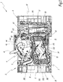
- the Figures 1 to 5 represent an apparatus for breaking an electric current, for example a circuit breaker.
- the apparatus 1 is a unipolar circuit breaker with alternating current or continuous low voltage and high intensity.
- the apparatus 1 is adapted to operate with electrical voltages of less than 1500 V DC or 1000 V AC and with electric currents of short circuit of intensity greater than or equal to 1 kA.
- the apparatus 1 may be different, for example, be a multipole circuit breaker.
- the apparatus 1 is intended to be connected to an electrical circuit for protection against electrical faults.
- electrical fault is meant here a short circuit or an overcurrent of the electric current flowing in the device.
- the apparatus 1 comprises a cut-off block 2 including a cut-off member 3, also called cut-off assembly, a control mechanism 4 and a casing 5.
- the apparatus 1 also comprises a trigger block 6, described in greater detail in FIG. what follows.
- the cut-off member 3 and the control mechanism 4 are housed inside the casing 5, in internal compartments distinct from this casing 5.
- the member 3 is switchable, reversibly and selectively, between two stable and distinct states, said open state and closed state.
- the member 3 In the closed state, the member 3 allows the circulation of an electric current within the apparatus 1, for example between connection areas of this apparatus 1.
- the member 3 prevents the circulation of an electric current in the absence of an electric arc within the apparatus 1.
- opening of the member 3 means switching the member 3 from the closed state to the open state.
- the member 3 comprises separable electrical contacts made of an electrically conductive material, such as copper. More specifically, the apparatus 1 here comprises fixed electrical contacts 31 and movable electrical contacts 32, the latter being movable relative to the fixed electrical contacts 31.
- the fixed and movable electrical contacts 31 and 31 are here provided with electrically conductive contact pads respectively denoted 331 and 332.
- the fixed and movable electrical contacts 31 and 32 are in contact with each other. Their respective contact pads 331, 332 are in direct contact, so as to allow the passage of current between these electrical contacts 31 and 32.
- the electrical contacts 32 are remote from the fixed electrical contacts 31, so that their respective contact pads 331, 332 are electrically insulated by the ambient air.
- the movable contacts 32 are formed by a single piece of electrically conductive material, which is carried by a rotary member 34 rotatably mounted relative to the housing 5.
- the fixed contacts 31 are here two in number and are arranged symmetrically with respect to the axis of rotation of the member 34.
- the member 3 also comprises arc breaking chambers 35, the role of which is to ensure the extinction of this electric arc.
- the breaking chamber 35 comprises a stack of cutting plates 351, as well as a channel 352 for evacuating the cutoff gases, which fluidly connects the breaking chamber to the outside of the casing 5.
- the chambers 35 are here two in number and are each placed at a contact zone between a fixed contact 31 and a movable contact 32.
- the control mechanism 4 makes it possible to control the switching of the member 3 between the open and closed states.
- the mechanism 4 is here mechanically coupled with the rotary member 34, so that a specific action on the mechanism 4 drives the electrical contacts 31 and 32 in displacement to switch the member 3 between the open states. and closed.
- the control mechanism 4 comprises a lever 41, also called a crankpin, which is accessible from outside the housing 5 and which is intended to be handled by an operator to switch, through the mechanism 4, the cutoff member between the open and closed positions. To the figure 1 the lever 41 is in a position corresponding to the closed state of the cut-off member 3.
- the control mechanism 4 also comprises a trigger member 42.
- the member 42 is movable between a rest position and a trigger position. When the member 42 moves from the rest position to the trigger position, it triggers the mechanism 4, which then switches the member 3 to the open state. Once the member 3 is in the open state, it remains in this open state.
- the mechanism 4 must be rearmed, for example by means of a manual action of an operator on the lever 41, to allow again the passage of the member 3 in its closed state.
- the member 42 is then returned to its rest position by the mechanism 4, for example by means of a spring 422.
- Mechanism 4 is here a rocking mechanism, also called "tumbler" in English. Such a mechanism is well known and, for example, is described in the patent application EP 0555158 A1 .
- the mechanism 4 comprises the trigger member 42, a hook 43, a lock 44 and a connecting rod 45, the latter providing the mechanical coupling between the mechanism 4 and the rotary member 34.
- the hook 43 is subject to an elastic restoring force, which tends to bring it back to a position corresponding to the open state of the member 3. This return movement is inhibited by the hooking of one end of the hook 43 on the latch 44, both that the latter is itself kept hooked to the trigger member 42 as long as it is in its rest position.
- the triggering member 42 is here mounted in rotation, between its resting and tripping positions, about an axis of rotation X42 perpendicular to the side walls of the casing 5.
- the trigger member 42 is here provided with a projecting lug 421, extending perpendicularly to the axis of rotation X42, the function of which is described in more detail in the following.
- the trigger block 6 is configured to trigger the switching of the member 3 to the open state, through the mechanism 4, when an electrical fault is detected from the current flowing through the device 1.
- the trigger block 6 comprises for this purpose a trigger 61, here of magneto-thermal type, which is adapted to monitor the electric current flowing in the trigger block and to move a striker 62 mobile block 6 when it detects the appearance of an electrical fault.
- a trigger is well known to those skilled in the art and is not described here in more detail.
- the block 6 is also provided with a connector 63 intended to be connected to the breaking block 2.
- the triggering unit 6 is attached to the breaking block 2 and the connector 63 is electrically connected to a corresponding fixed electrical contact 31 of the member 3.
- the triggering block 6 can react according to the current flowing through the electrical device 1.
- connection areas of the device 1 There are “11” and “12” of the connection areas of the device 1. These areas 11 and 12 make it possible to connect the device 1 to the electrical circuit that it must protect.
- the range 11 here corresponds to one end of one of the fixed electrical contacts 31, while the range 12 corresponds to an outer end of the connector 63.
- the trigger 61 When an electrical fault is detected by the trigger 61, the latter moves the striker 62, which then exerts a mechanical force on the trigger member 42, so as to move it to its trigger position. In response, the control mechanism is triggered and causes switching and then maintaining the breaking device 3 in the open state, so as to interrupt the flow of electric current between the areas 11 and 12.
- the casing 5 forms an outer casing of the cutoff block 2.
- the trigger block 6 is detachable from the cutoff block 2.
- the casing 5 forms an envelope of the only cutoff block 2.
- the casing 5 surrounds at least the member 3 and the mechanism 4.
- the triggering block 6 has its own case.
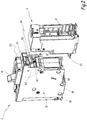
- the housing 5 comprises in particular side walls 51, 52 which delimit opposite side faces of the cutoff block 2.
- the lever 41 is located on a front face of the device 1.
- the lateral faces extend perpendicularly to this front face and perpendicular to the lower and upper faces of the cutoff block 2.
- the triggering unit 6 is here attached to the cutoff block 2 on a lower face of this cutoff block 2.
- the side walls 51 and 52 are deformable, reversibly, between a normal state and a deformed state.
- the side walls 51 and 52 have a substantially planar shape and extend parallel to each other.
- each wall 51, 52 has a curved shape towards the outside of the apparatus 1, as illustrated in FIG. figure 4 .
- the amplitude of the deformation of each wall 51, 52 is, for example, measured as the distance between the positions of the center of this wall between the normal and deformed states.
- the walls 51 and 52 are simultaneously either in their normal state or in their deformed state, since they surround the same member 3. However, when they are in a deformed state, they may not have a deformation strictly identical, that is to say of the same shape or the same amplitude, due in particular to the arrangement of the constituents of the apparatus 1 inside the housing 5.
- the dashed lines bearing the references 51d and 52d illustrate the position of the side walls, respectively 51 and 52, when they are in the deformed state.
- the walls 51 and 52 elastically deform from their normal state to their deformed state as the pressure inside the housing 5 increases.
- a deformation greater than or equal to 1 mm is observed when the pressure exceeds a value of 6 bars, this deformation being here measured along an axis parallel to the axis X42.
- Such an increase in pressure is caused by the appearance of the electric arc during the separation between the fixed contacts 31 and the movable contacts 32 of the member 3.
- the increase in pressure is such that the cutoff gas generated by the electric arc can not be instantly discharged into the outlet channel 352. They then spread inside the housing 5 and generate an overpressure, compared to the pressure that normally prevails in this housing 5. For example the pressure increases until it is greater than or equal to 6 bars, or even greater than or equal to 20 bars.
- the electric arc must be interrupted as soon as possible to limit this overpressure. For example, it is desirable to open the member 3 before the pressure in the housing becomes greater than or equal to 5 bars.
- the housing 5 is made from a thermoplastic material, for example by molding.
- the walls 51 and 52 are made of the same material as the housing 5.
- the walls 51 and 52 have a modulus of elasticity of between 1 GPa and 5 GPa.
- the walls 51 and 52 are resistant to impacts and in particular have an impact resistance greater than or equal to 10 kJ / m 2 .
- This impact resistance is here measured with the so-called Charpy test method as defined by the ISO 179 / 1eA standard, performed at room temperature and with a probe of dimensions 80x10x3 mm.
- the housing 5, and therefore the walls 51 and 52 are made of glass fiber reinforced polycarbonate.
- polycarbonate resin marketed under the reference LEXAN® EXL5689 by the company SABIC is used.
- polycarbonate resin sold under the reference XANTAR® XRM5010 may be used instead by MITSUBISHI ENGINEERING PLASTICS CORPORATION.
- the walls 51, 52 each have a thickness greater than or equal to 1 mm and less than or equal to 3 mm, this thickness being measured when the walls 51, 52 are in the idle state.
- the walls 51, 52 return to their state of rest when the pressure in the housing 5 becomes equal to the surrounding atmospheric pressure, without the housing 5 suffering from mechanical sequelae detrimental to its operation.
- the housing 5 is here formed by two molded half-shells, similar and complementary in shape to each other, each carrying a wall 51, 52. These two half-shells are intended to be secured to one another to ensure the integrity of the housing 5.
- the housing 5 comprises means for fixing the walls 51, 52.
- the fastening means are rivets, whose respective heads are referenced 55.
- the walls 51, 52 then comprise through holes to allow the passage of these rivets.
- the fixing means are arranged only near the edges of the walls 51, 52, so as not to hinder their deformation.
- the housing 5 also includes a window 54 which at least partially exposes the trigger member 42 outside the housing 5. In this way, the striker 62 can act mechanically on the member 42, even though the striker 62 is located outside the housing 5.
- the trigger 61 and the striker 62 can be housed inside the housing 5.
- the window 54 can be omitted.
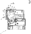
- one of the side walls in this case here the side wall 52, further comprises, on its inner face 521, a rigid protrusion 53 which extends inwardly of the housing 5, perpendicular to this inner face 521
- the protrusion 53 is integral with the wall 52, preferably without degree of freedom in flexion.
- the inner face 521 is here the face of the lateral wall 52 which is turned towards the interior of the housing 5. This inner face 521 is opposite to the outer face of the lateral wall 52.
- the protrusion 53 Due to its attachment to the deformable side wall 52, the protrusion 53 is movable between a first position and a second position. The protrusion 53 is in the first position when the side wall 52 is in the normal state, and in the second position when the side wall 52 is in the deformed state.
- the protrusion 53 moves to its second position as the corresponding side wall 52 deforms from its normal state to its deformed state.
- the protrusion 53 is formed in one piece with the corresponding lateral wall 52.
- the protrusion 53 is integral with the wall 52. This makes it possible to further simplify the manufacture of the device 1, since the protrusion 53 is then manufactured simultaneously with the side wall 52, for example during a single molding operation.
- the protrusion 53 may be an insert separate from the wall 52 and which is fixed integrally to the wall 52.
- this fixing is performed by means of a rivet or by gluing or welding.
- X53 is the longitudinal axis along which the protrusion 53 extends when it is in its first position and X53d the direction in which the protrusion extends when it is in the second position.
- the axis X53 is here perpendicular to the walls 51 and 52 when they are in their state of rest.
- the angle between the axes X53 and X53d is greater than or equal to 8 ° when the wall 52 is deformed by an amplitude greater than or equal to 1 mm.
- the protrusion 53 is arranged relative to the trigger member 42 so that its displacement from its first position to its second position causes a displacement of the trigger member 42 from its inactive position to its trigger position. In this way, the displacement of the protrusion 53 resulting from the deformation of the walls 51, 52 causes the trigger mechanism 4 to switch the cutoff member 3 to its open state.
- the protrusion 53 is here coupled with the triggering member 42.
- the pin 421 is here placed on the path followed by the protrusion 53 between its first and second positions.
- the protrusion 53 is here disposed above the lug 421.
- the protrusion 53 when the protrusion 53 is in its first position and the member 42 is in its rest position, then the lower face of the beam 531 is in contact with the lug 421 without exerting any effort on this When it passes into its second position, the protrusion 53 presses on the lug 421, since it is situated on its trajectory, and drives the latter in rotation about the axis X42.
- the dimensions of the protrusion 53 are also chosen as a function of the force that it is necessary to apply to the lug 421 in order to move the member 42 towards its tripping position.
- the protrusion 53 is adapted to exert a force on the lug 421 of intensity greater than or equal to 5 Newton when it moves towards its second position.
- the lug 421 advantageously serves as a lever and makes it possible to reduce the force required to rotate the member 42.
- the length of the protrusion 53, the length of the lug 421 and the relative position of the lug 421 with respect to the protrusion 53, are adapted to benefit from a leverage effect, which reduces the the force required to move the trigger member 42 to its trigger position.
- the zone of contact between the protrusion 53 and the lug 421 is located at a distance from the inner face 521 which is greater than or equal to one-third of the width of the member 3, more preferably equal to half of this width.
- the contact zone is here the surface portion of the pin 421 on which the protrusion 53 presses when it moves towards its second position while the member 42 is in its rest position.
- This width is, for example, measured along the axis X53.
- this width is equal to the spacing between the side walls 51 and 52.
- the length of the protrusion 53 is preferably greater than or equal to 10 mm.
- the length of the protrusion 53 is here measured along the axis X53 when it is in its first position.
- the pin 421 is dimensioned so that the distance between said contact zone and the axis X42 is equal, for example to within 5%, to the distance between the axis X42 and the zone hooking the member 42 to the lock 44.
- the projection 53 comprises a beam 531 and a stiffener 532.
- the beam 531 and the stiffener 532 are here made of the same material.
- the beam 531 extends longitudinally along the axis X53 and has a cylindrical shape with a cross section of area greater than or equal to 5 mm 2 .
- the stiffener 532 here comprises a triangular-shaped flat wall which extends under this beam 531 and which is anchored to the inner face 521 along one of its sides and anchored to the beam 531 along another of its sides.
- the choice of the dimensions of the protrusion 53, in particular its shape and / or section, as well as the use of the stiffener 532, make it possible to increase the stiffness of the protrusion 53. This is particularly useful when the protrusion 53 is made in one piece with the side wall 52. Indeed, the protrusion is then made of the same material as the side wall 52. Now, this material is deformable, while it is precisely desired to prevent the protrusion 53 it itself does not deform when it exerts a support on the organ 42.
- the protrusion 53 thus makes it possible to trigger the control mechanism 4 during the occurrence of an electric arc between electrical contacts 31, 32, which generates a clearance of cut-off gas and therefore an overpressure in the housing 5.
- the protrusion 53 then exerts a force on the lug 421, which causes the displacement of the trigger member 42 towards its trigger position, as illustrated by the arrow F3 at the figure 5 . Because of the design of the mechanism 4, this movement of the member 42 in turn causes the switching of the member 3 to its open state, as explained above.
- the electrical contacts 31 and 32 are then kept separate, thus ensuring the stop of the flow of electric current.
- the increase in pressure which results from the appearance of the electric arc causes the deformation of the side walls 51, 52 and therefore the triggering of the mechanism 4, via the protrusion 53.
- the trigger mechanism 4 is achieved quickly, since the trigger chain is shorter than in known devices, because of the absence of an intermediate element such as a piston.
- the overpressure triggers the trigger mechanism 4 after a period of less than or equal to 1 ms.
- the trigger 61 comes into action, moving the firing pin 62, after a period of 3 ms.
- the manufacture of the device 1 is simpler and more economical. This also gives the device 1 a better robustness, insofar as the operation of the protrusion 53, because of its simplicity, is not sensitive to a possible risk of pollution by the cutoff gases.
- protrusion 53 is configured to act on the trigger member 42 triggers the mechanism 4 using the same control chain as the trigger 61. It is therefore not necessary to change the architecture mechanisms existing controls, and to increase the external volume and size of the cut-off block 2.
- the invention thus makes it possible to use the deformation of the side walls 51 and 52 caused by the overpressure due to the cutting gas, which is traditionally perceived as a harmful and undesirable effect, in order to control the triggering of the mechanism 4 quickly and reliably and with a simplified implementation.
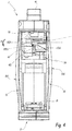
- the figure 6 represents an electrical switching device 1 'according to the second embodiment of the invention.
- the elements of the apparatus 1 'of this embodiment which are analogous to the switchgear 1 bear the same references increased by the symbol "'" and are not described in more detail, since the description below above can be transposed to them.
- the apparatus 1 is a bipolar electric circuit breaker, adapted to operate with electric currents flowing along two distinct electric poles P1 and P2.
- the apparatus 1 here comprises a breaking block 2' and a trigger block 6 ', which play the same role, respectively, as the blocks 2 and 6 of the apparatus 1.
- Block 2 'differs in particular from block 2 in that it comprises two cut-off devices, or cut-off assemblies, each associated with one of the electric poles P1 and P2.
- the apparatus 1 'then comprises a plurality of connection pads associated with each of the poles P1 and P2.
- the block 2 ' also comprises a control mechanism similar to the mechanism 4, in particular provided with a lever 41' and a trigger member 42 'including a lug 421'.
- the control mechanism of the block 2 ' is arranged to simultaneously control the two cut-off members of the block 2' in the same state, in particular to open simultaneously the two cut-off members of the poles P1 and P2.
- the apparatus 1 ' comprises a housing similar to the housing 5 and inside which the block 2' is housed.
- This housing has deformable side walls 51 'and 52' similar to the walls 51, 52.
- the wall 52 ' carries a protrusion 53' which plays the same role as the protrusion 53.
- the protrusion 53 ' is adapted to move towards its second position when the wall 52' is deformed, under the effect of an increase in the pressure in the housing, resulting from the occurrence of an electric arc in at least one of the cut-off members of the block 2 '.
- the protrusion 53 ' exerts a force on the lug 421', which moves the member 42 'towards its release position in order to open the cut-off members of the block 2'.
- the invention is easily applicable to devices other than the apparatus 1, without the need to modify their architecture in depth.
- the distance previously defined between the contact zone and the wall 52' is here equal to the distance between the wall 52 'and the geometric plane separating one on the other, the two cut-off members of the block 2 '.
- the apparatus 1 ' also comprises a cover 500 intended to cover a front face of the apparatus 1'.
- This cover 500 is provided with lateral flanges 502 folded which are intended to cover the front edge of the side faces 51 ', 52' when the cover 500 is in configuration mounted on the apparatus 1 '.
- the dimensions of the flanges 502 are limited so as not to hinder the deformation of the walls 51 'and 52'.
Claims (10)
- Vorrichtung (1; 1') zum Trennen eines elektrischen Stroms mit trennbaren elektrischen Kontakten und in Luft schaltend, wobei diese Vorrichtung umfasst:- eine Trennbaugruppe (3), die zwischen einem offenen Zustand, der das Fließen eines elektrischen Stroms in der Vorrichtung ermöglicht, und einem geschlossenen Zustand, der das Fließen des elektrischen Stroms verhindert, schaltbar ist;- einen Mechanismus (4) zum Steuern des Schaltens der Trennbaugruppe (3) zwischen ihrem offenen und geschlossenen Zustand, wobei dieser Steuermechanismus (4) ein Auslöseelement (42; 42') umfasst, das zum Auslösen des Schaltens der Trennbaugruppe (3) in den offenen Zustand ausgebildet ist, wenn dieses Auslöseelement (42; 42') von einer Ruhestellung in eine Auslösestellung bewegt wird;- ein Gehäuse (5), in dessen Innerem die Trennbaugruppe (3) und der Steuermechanismus (4) aufgenommen sind und das Seitenwände (51, 52; 51', 52') umfasst;wobei diese Trennvorrichtung (1; 1') dadurch gekennzeichnet ist, dass:- die Seitenwände (51, 52; 51', 52') elastisch von einem Ruhezustand in einen verformten Zustand verformbar sind, wenn der im Inneren des Gehäuses (5) herrschende Druck steigt;- eine der Seitenwände (52; 52') an ihrer Innenfläche (521) einen starren Ansatz (53; 53') aufweist, der sich ins Innere des Gehäuses senkrecht zu dieser Innenfläche (521) erstreckt, derart dass die Verformung der Seitenwand (52; 52') eine Verschiebung des Ansatzes (53; 53') von einer ersten Position in eine zweite Position mit sich bringt;- der Ansatz (53; 53') in Bezug auf das Auslöseelement derart angeordnet ist, dass seine Verschiebung in die zweite Position die Verschiebung des Auslöseelementes (42; 42') von der Ruhestellung in die Auslösestellung bewirkt.
- Trennvorrichtung (1; 1') nach Anspruch 1, dadurch gekennzeichnet, dass der Ansatz (53; 53') in einem Stück mit der Seitenwand (52; 52') ausgebildet ist.
- Trennvorrichtung (1; 1') nach einem beliebigen der vorhergehenden Ansprüche, dadurch gekennzeichnet, dass die Seitenwände (51, 52; 51', 52') aus einem gegossenen thermoplastischen Material hergestellt sind.
- Trennvorrichtung (1; 1') nach Anspruch 3, dadurch gekennzeichnet, dass die Seitenwände (51, 52; 51', 52') aus einem Polycarbonatharz, das durch Glasfasern verstärkt ist, hergestellt sind.
- Trennvorrichtung (1; 1') nach einem beliebigen der vorhergehenden Ansprüche, dadurch gekennzeichnet, dass die Seitenwände (51, 52; 51', 52') einen Biegeelastizitätsmodul aufweisen, der größer als oder gleich 1 GPa ist und kleiner als oder gleich 5 GPa ist, derart dass die Amplitude der Verformung der Seitenwände (51, 52; 51' 52') größer als oder gleich 1 mm ist, wenn der Druck im Inneren des Gehäuses größer als oder gleich 6 bar ist.
- Trennvorrichtung (1; 1') nach einem beliebigen der vorhergehenden Ansprüche, dadurch gekennzeichnet, dass der Ansatz (53; 53') einen starren Balken (531), der sich gemäß einer Längsachse (X53) des Ansatzes (53; 53') erstreckt, und ein Versteifungselement (532) aufweist.
- Trennvorrichtung (1; 1') nach einem beliebigen der vorhergehenden Ansprüche, dadurch gekennzeichnet, dass dieser Ansatz (53; 53') eine Länge größer als oder gleich 5 mm aufweist.
- Trennvorrichtung (1; 1') nach einem beliebigen der vorhergehenden Ansprüche, dadurch gekennzeichnet, dass das Auslöseelement (42; 42') um eine Drehachse (X42) drehbeweglich ist und mit einem vorspringenden Zapfen (421; 421') versehen ist, der sich senkrecht zur Drehachse (X42) erstreckt, wobei der Zapfen (421; 421') auf dem Weg liegt, der von dem Ansatz (53; 53') verfolgt wird, wenn er sich von der ersten Position in die zweite Position bewegt.
- Trennvorrichtung (1; 1') nach Anspruch 8, dadurch gekennzeichnet, dass eine Kontaktzone zwischen dem Ansatz und dem Zapfen (421; 421') in einem Abstand zur Innenfläche (521) liegt, der größer als oder gleich einem Drittel der Breite der Trennbaugruppe (3) ist.
- Trennvorrichtung (1; 1') nach einem beliebigen der vorhergehenden Ansprüche, dadurch gekennzeichnet, dass sie einen Auslöseblock (6) aufweist, der einen Auslöser (61) und einen beweglichen Schlagkörper (62) aufweist, wobei der Auslöser (61) vorgesehen ist, das Auslöseelement (42; 42') in seine Auslösestellung zu bewegen, wenn er einen elektrischen Fehler aus dem elektrischen Stroms, der durch die Vorrichtung (1; 1') fließt, detektiert.
Priority Applications (1)
| Application Number | Priority Date | Filing Date | Title |
|---|---|---|---|
| PL18157542T PL3367415T3 (pl) | 2017-02-22 | 2018-02-20 | Aparat odcinający prąd elektryczny posiadający separowalne styki oraz z odcinaniem w powietrzu |
Applications Claiming Priority (1)
| Application Number | Priority Date | Filing Date | Title |
|---|---|---|---|
| FR1751389A FR3063174B1 (fr) | 2017-02-22 | 2017-02-22 | Appareil de coupure d'un courant electrique a contacts electriques separables et a coupure dans l'air |
Publications (2)
| Publication Number | Publication Date |
|---|---|
| EP3367415A1 EP3367415A1 (de) | 2018-08-29 |
| EP3367415B1 true EP3367415B1 (de) | 2019-12-04 |
Family
ID=59381349
Family Applications (1)
| Application Number | Title | Priority Date | Filing Date |
|---|---|---|---|
| EP18157542.4A Active EP3367415B1 (de) | 2017-02-22 | 2018-02-20 | Stromunterbrechungsgerät mit trennbaren elektrischen kontakten und zur unterbrechung in der luft |
Country Status (9)
| Country | Link |
|---|---|
| US (1) | US10418215B2 (de) |
| EP (1) | EP3367415B1 (de) |
| JP (1) | JP7089894B2 (de) |
| KR (1) | KR102549652B1 (de) |
| CN (1) | CN108461359B (de) |
| BR (1) | BR102018001263B1 (de) |
| ES (1) | ES2770144T3 (de) |
| FR (1) | FR3063174B1 (de) |
| PL (1) | PL3367415T3 (de) |
Family Cites Families (10)
| Publication number | Priority date | Publication date | Assignee | Title |
|---|---|---|---|---|
| FR2661776B1 (fr) * | 1990-05-04 | 1996-05-10 | Merlin Gerin | Declencheur instantane d'un disjoncteur. |
| JP3399301B2 (ja) * | 1997-07-09 | 2003-04-21 | 三菱電機株式会社 | 回路遮断器 |
| JPH11224584A (ja) * | 1998-02-05 | 1999-08-17 | Fuji Electric Co Ltd | 回路遮断器のケースとカバーとの固定構造 |
| US6377144B1 (en) * | 1999-11-03 | 2002-04-23 | General Electric Company | Molded case circuit breaker base and mid-cover assembly |
| CN101241820B (zh) * | 2008-03-07 | 2010-06-30 | 常熟开关制造有限公司(原常熟开关厂) | 单极模块化的低压断路器 |
| DE102009015126A1 (de) * | 2009-03-31 | 2010-10-14 | Siemens Aktiengesellschaft | Auslöser für eine elektrische Schaltanordnung |
| FR2946192A1 (fr) * | 2009-05-28 | 2010-12-03 | Schneider Electric Ind Sas | Dispositif de limitation de la surpression a l'interieur d'un compartiment appartenant a un appareil electrique |
| CN102299032B (zh) * | 2011-08-09 | 2016-04-13 | 无锡新宏泰电器科技股份有限公司 | 断路器直驱式气吹脱扣装置 |
| CN103903928B (zh) * | 2014-04-16 | 2016-05-11 | 南京大全电气研究院有限公司 | 一种具有对流散热壳体的断路器 |
| FR3042640B1 (fr) * | 2015-10-20 | 2019-05-31 | Schneider Electric Industries Sas | Appareil de commutation electrique comportant un mecanisme de commutation et au moins un module auxiliaire |
-
2017
- 2017-02-22 FR FR1751389A patent/FR3063174B1/fr active Active
-
2018
- 2018-01-22 BR BR102018001263-0A patent/BR102018001263B1/pt active IP Right Grant
- 2018-01-24 US US15/878,861 patent/US10418215B2/en active Active
- 2018-02-09 CN CN201810133151.2A patent/CN108461359B/zh active Active
- 2018-02-20 PL PL18157542T patent/PL3367415T3/pl unknown
- 2018-02-20 ES ES18157542T patent/ES2770144T3/es active Active
- 2018-02-20 EP EP18157542.4A patent/EP3367415B1/de active Active
- 2018-02-21 KR KR1020180020790A patent/KR102549652B1/ko active IP Right Grant
- 2018-02-21 JP JP2018029003A patent/JP7089894B2/ja active Active
Non-Patent Citations (1)
| Title |
|---|
| None * |
Also Published As
| Publication number | Publication date |
|---|---|
| FR3063174B1 (fr) | 2019-04-19 |
| CN108461359A (zh) | 2018-08-28 |
| EP3367415A1 (de) | 2018-08-29 |
| JP7089894B2 (ja) | 2022-06-23 |
| JP2018137226A (ja) | 2018-08-30 |
| KR20180097156A (ko) | 2018-08-30 |
| US10418215B2 (en) | 2019-09-17 |
| BR102018001263A2 (pt) | 2018-10-30 |
| KR102549652B1 (ko) | 2023-06-29 |
| ES2770144T3 (es) | 2020-06-30 |
| FR3063174A1 (fr) | 2018-08-24 |
| US20180240632A1 (en) | 2018-08-23 |
| PL3367415T3 (pl) | 2020-06-01 |
| BR102018001263B1 (pt) | 2023-12-26 |
| CN108461359B (zh) | 2021-10-29 |
Similar Documents
| Publication | Publication Date | Title |
|---|---|---|
| EP0225207B1 (de) | Kinematische Übertragungskette zwischen dem Steuermechanismus und den Polen eines elektrischen Lastschalters mit einem gespritzten Isoliergehäuse | |
| FR2891661A1 (fr) | Disjoncteur multipolaire. | |
| EP1743346B1 (de) | Überspannungsschutzeinrichtung mit lichtbogenlöschelementen | |
| EP1815569B1 (de) | Überspannungsschutzeinrichtung mit verbesserter trennung | |
| EP2478544A1 (de) | Einpolige trenneinheit mit einem drehgrenztaster, trennvorrichtung mit einer derartigen einheit und schutzschalter mit einer derartigen vorrichtung | |
| EP2330611B1 (de) | Selektiv-Leistungsschalter | |
| EP3367415B1 (de) | Stromunterbrechungsgerät mit trennbaren elektrischen kontakten und zur unterbrechung in der luft | |
| EP1842269A2 (de) | Einrichtung zum schutz elektrischer installationen mit verbesserter unterbrecherkapazität | |
| EP2743958B1 (de) | Elektrisches Stromschaltgerät, insbesondere Abzweigschalter | |
| EP2894647A1 (de) | Unipolarer Abschaltblock und mit einem solchen Block ausgestattete Abschaltvorrichtung | |
| EP0118334B2 (de) | Strombegrenzender Schalter | |
| EP3499541B1 (de) | Elektrisches schutzgerät, das ein pyrotechnisches betätigungssystem umfasst | |
| EP0996959B1 (de) | Elektrischer leistungsschalter für elektrische anlagen mit niederwechselspannung | |
| EP1829176B1 (de) | Überspannungs-schutzeinrichtung mit verbesserter trennung und entsprechendes verfahren | |
| FR2958447A1 (fr) | Declencheur electromagnetique pour appareil electrique interrupteur, appareil electrique interrupteur comportant un tel declencheur | |
| EP0054499B1 (de) | Schalter mit Trennung des Nulleiters | |
| EP2743947B1 (de) | Kontaktarme tragende Schaltwelle in einem Schaltgerät, und damit versehenes Schaltgerät, insbesondere ein Abzweigschalter | |
| EP3161850B1 (de) | Thermisch-magnetischer auslösungsmechanismus | |
| FR2981789A1 (fr) | Dispositif de coupure electrique comportant un pont mobile de contact | |
| FR2982995A1 (fr) | Dispositif de coupure a ecran pour contacteur | |
| FR2986659A1 (fr) | Bloc de coupure unipolaire et dispositif de coupure comportant un tel bloc | |
| EP3857585B1 (de) | Einrichtung zur löschung eines lichtbogens für eine elektrische schutzvorrichtung und elektrische schutzvorrichtung mit dieser vorrichtung | |
| FR2844915A1 (fr) | Dispositif de declenchement pour appareil electrique interrupteur | |
| EP4298653A1 (de) | Elektrische vorrichtung und abschaltsystem mit einer solchen vorrichtung | |
| EP4186084A1 (de) | Lichtbogenlöschkammer für eine elektrische schutzvorrichtung und elektrische schutzvorrichtung mit mindestens einer solchen löschkammer |
Legal Events
| Date | Code | Title | Description |
|---|---|---|---|
| PUAI | Public reference made under article 153(3) epc to a published international application that has entered the european phase |
Free format text: ORIGINAL CODE: 0009012 |
|
| STAA | Information on the status of an ep patent application or granted ep patent |
Free format text: STATUS: THE APPLICATION HAS BEEN PUBLISHED |
|
| AK | Designated contracting states |
Kind code of ref document: A1 Designated state(s): AL AT BE BG CH CY CZ DE DK EE ES FI FR GB GR HR HU IE IS IT LI LT LU LV MC MK MT NL NO PL PT RO RS SE SI SK SM TR |
|
| AX | Request for extension of the european patent |
Extension state: BA ME |
|
| STAA | Information on the status of an ep patent application or granted ep patent |
Free format text: STATUS: REQUEST FOR EXAMINATION WAS MADE |
|
| 17P | Request for examination filed |
Effective date: 20190201 |
|
| RBV | Designated contracting states (corrected) |
Designated state(s): AL AT BE BG CH CY CZ DE DK EE ES FI FR GB GR HR HU IE IS IT LI LT LU LV MC MK MT NL NO PL PT RO RS SE SI SK SM TR |
|
| GRAP | Despatch of communication of intention to grant a patent |
Free format text: ORIGINAL CODE: EPIDOSNIGR1 |
|
| STAA | Information on the status of an ep patent application or granted ep patent |
Free format text: STATUS: GRANT OF PATENT IS INTENDED |
|
| RIC1 | Information provided on ipc code assigned before grant |
Ipc: H01H 9/34 20060101ALN20190626BHEP Ipc: H01H 71/02 20060101AFI20190626BHEP |
|
| INTG | Intention to grant announced |
Effective date: 20190715 |
|
| GRAS | Grant fee paid |
Free format text: ORIGINAL CODE: EPIDOSNIGR3 |
|
| GRAA | (expected) grant |
Free format text: ORIGINAL CODE: 0009210 |
|
| STAA | Information on the status of an ep patent application or granted ep patent |
Free format text: STATUS: THE PATENT HAS BEEN GRANTED |
|
| AK | Designated contracting states |
Kind code of ref document: B1 Designated state(s): AL AT BE BG CH CY CZ DE DK EE ES FI FR GB GR HR HU IE IS IT LI LT LU LV MC MK MT NL NO PL PT RO RS SE SI SK SM TR |
|
| REG | Reference to a national code |
Ref country code: GB Ref legal event code: FG4D Free format text: NOT ENGLISH |
|
| REG | Reference to a national code |
Ref country code: CH Ref legal event code: EP |
|
| REG | Reference to a national code |
Ref country code: AT Ref legal event code: REF Ref document number: 1210440 Country of ref document: AT Kind code of ref document: T Effective date: 20191215 |
|
| REG | Reference to a national code |
Ref country code: DE Ref legal event code: R096 Ref document number: 602018001423 Country of ref document: DE |
|
| REG | Reference to a national code |
Ref country code: IE Ref legal event code: FG4D Free format text: LANGUAGE OF EP DOCUMENT: FRENCH |
|
| REG | Reference to a national code |
Ref country code: NL Ref legal event code: MP Effective date: 20191204 |
|
| REG | Reference to a national code |
Ref country code: LT Ref legal event code: MG4D |
|
| PG25 | Lapsed in a contracting state [announced via postgrant information from national office to epo] |
Ref country code: GR Free format text: LAPSE BECAUSE OF FAILURE TO SUBMIT A TRANSLATION OF THE DESCRIPTION OR TO PAY THE FEE WITHIN THE PRESCRIBED TIME-LIMIT Effective date: 20200305 Ref country code: LT Free format text: LAPSE BECAUSE OF FAILURE TO SUBMIT A TRANSLATION OF THE DESCRIPTION OR TO PAY THE FEE WITHIN THE PRESCRIBED TIME-LIMIT Effective date: 20191204 Ref country code: FI Free format text: LAPSE BECAUSE OF FAILURE TO SUBMIT A TRANSLATION OF THE DESCRIPTION OR TO PAY THE FEE WITHIN THE PRESCRIBED TIME-LIMIT Effective date: 20191204 Ref country code: BG Free format text: LAPSE BECAUSE OF FAILURE TO SUBMIT A TRANSLATION OF THE DESCRIPTION OR TO PAY THE FEE WITHIN THE PRESCRIBED TIME-LIMIT Effective date: 20200304 Ref country code: LV Free format text: LAPSE BECAUSE OF FAILURE TO SUBMIT A TRANSLATION OF THE DESCRIPTION OR TO PAY THE FEE WITHIN THE PRESCRIBED TIME-LIMIT Effective date: 20191204 Ref country code: SE Free format text: LAPSE BECAUSE OF FAILURE TO SUBMIT A TRANSLATION OF THE DESCRIPTION OR TO PAY THE FEE WITHIN THE PRESCRIBED TIME-LIMIT Effective date: 20191204 Ref country code: NO Free format text: LAPSE BECAUSE OF FAILURE TO SUBMIT A TRANSLATION OF THE DESCRIPTION OR TO PAY THE FEE WITHIN THE PRESCRIBED TIME-LIMIT Effective date: 20200304 |
|
| PG25 | Lapsed in a contracting state [announced via postgrant information from national office to epo] |
Ref country code: HR Free format text: LAPSE BECAUSE OF FAILURE TO SUBMIT A TRANSLATION OF THE DESCRIPTION OR TO PAY THE FEE WITHIN THE PRESCRIBED TIME-LIMIT Effective date: 20191204 Ref country code: RS Free format text: LAPSE BECAUSE OF FAILURE TO SUBMIT A TRANSLATION OF THE DESCRIPTION OR TO PAY THE FEE WITHIN THE PRESCRIBED TIME-LIMIT Effective date: 20191204 |
|
| PG25 | Lapsed in a contracting state [announced via postgrant information from national office to epo] |
Ref country code: AL Free format text: LAPSE BECAUSE OF FAILURE TO SUBMIT A TRANSLATION OF THE DESCRIPTION OR TO PAY THE FEE WITHIN THE PRESCRIBED TIME-LIMIT Effective date: 20191204 |
|
| REG | Reference to a national code |
Ref country code: ES Ref legal event code: FG2A Ref document number: 2770144 Country of ref document: ES Kind code of ref document: T3 Effective date: 20200630 |
|
| PG25 | Lapsed in a contracting state [announced via postgrant information from national office to epo] |
Ref country code: CZ Free format text: LAPSE BECAUSE OF FAILURE TO SUBMIT A TRANSLATION OF THE DESCRIPTION OR TO PAY THE FEE WITHIN THE PRESCRIBED TIME-LIMIT Effective date: 20191204 Ref country code: NL Free format text: LAPSE BECAUSE OF FAILURE TO SUBMIT A TRANSLATION OF THE DESCRIPTION OR TO PAY THE FEE WITHIN THE PRESCRIBED TIME-LIMIT Effective date: 20191204 Ref country code: RO Free format text: LAPSE BECAUSE OF FAILURE TO SUBMIT A TRANSLATION OF THE DESCRIPTION OR TO PAY THE FEE WITHIN THE PRESCRIBED TIME-LIMIT Effective date: 20191204 Ref country code: EE Free format text: LAPSE BECAUSE OF FAILURE TO SUBMIT A TRANSLATION OF THE DESCRIPTION OR TO PAY THE FEE WITHIN THE PRESCRIBED TIME-LIMIT Effective date: 20191204 Ref country code: PT Free format text: LAPSE BECAUSE OF FAILURE TO SUBMIT A TRANSLATION OF THE DESCRIPTION OR TO PAY THE FEE WITHIN THE PRESCRIBED TIME-LIMIT Effective date: 20200429 |
|
| PG25 | Lapsed in a contracting state [announced via postgrant information from national office to epo] |
Ref country code: IS Free format text: LAPSE BECAUSE OF FAILURE TO SUBMIT A TRANSLATION OF THE DESCRIPTION OR TO PAY THE FEE WITHIN THE PRESCRIBED TIME-LIMIT Effective date: 20200404 Ref country code: SK Free format text: LAPSE BECAUSE OF FAILURE TO SUBMIT A TRANSLATION OF THE DESCRIPTION OR TO PAY THE FEE WITHIN THE PRESCRIBED TIME-LIMIT Effective date: 20191204 Ref country code: SM Free format text: LAPSE BECAUSE OF FAILURE TO SUBMIT A TRANSLATION OF THE DESCRIPTION OR TO PAY THE FEE WITHIN THE PRESCRIBED TIME-LIMIT Effective date: 20191204 |
|
| REG | Reference to a national code |
Ref country code: DE Ref legal event code: R097 Ref document number: 602018001423 Country of ref document: DE |
|
| REG | Reference to a national code |
Ref country code: AT Ref legal event code: MK05 Ref document number: 1210440 Country of ref document: AT Kind code of ref document: T Effective date: 20191204 |
|
| PLBE | No opposition filed within time limit |
Free format text: ORIGINAL CODE: 0009261 |
|
| STAA | Information on the status of an ep patent application or granted ep patent |
Free format text: STATUS: NO OPPOSITION FILED WITHIN TIME LIMIT |
|
| REG | Reference to a national code |
Ref country code: BE Ref legal event code: MM Effective date: 20200229 |
|
| PG25 | Lapsed in a contracting state [announced via postgrant information from national office to epo] |
Ref country code: DK Free format text: LAPSE BECAUSE OF FAILURE TO SUBMIT A TRANSLATION OF THE DESCRIPTION OR TO PAY THE FEE WITHIN THE PRESCRIBED TIME-LIMIT Effective date: 20191204 Ref country code: LU Free format text: LAPSE BECAUSE OF NON-PAYMENT OF DUE FEES Effective date: 20200220 Ref country code: MC Free format text: LAPSE BECAUSE OF FAILURE TO SUBMIT A TRANSLATION OF THE DESCRIPTION OR TO PAY THE FEE WITHIN THE PRESCRIBED TIME-LIMIT Effective date: 20191204 |
|
| 26N | No opposition filed |
Effective date: 20200907 |
|
| PG25 | Lapsed in a contracting state [announced via postgrant information from national office to epo] |
Ref country code: AT Free format text: LAPSE BECAUSE OF FAILURE TO SUBMIT A TRANSLATION OF THE DESCRIPTION OR TO PAY THE FEE WITHIN THE PRESCRIBED TIME-LIMIT Effective date: 20191204 Ref country code: SI Free format text: LAPSE BECAUSE OF FAILURE TO SUBMIT A TRANSLATION OF THE DESCRIPTION OR TO PAY THE FEE WITHIN THE PRESCRIBED TIME-LIMIT Effective date: 20191204 |
|
| PG25 | Lapsed in a contracting state [announced via postgrant information from national office to epo] |
Ref country code: IE Free format text: LAPSE BECAUSE OF NON-PAYMENT OF DUE FEES Effective date: 20200220 |
|
| PG25 | Lapsed in a contracting state [announced via postgrant information from national office to epo] |
Ref country code: BE Free format text: LAPSE BECAUSE OF NON-PAYMENT OF DUE FEES Effective date: 20200229 |
|
| PG25 | Lapsed in a contracting state [announced via postgrant information from national office to epo] |
Ref country code: CH Free format text: LAPSE BECAUSE OF NON-PAYMENT OF DUE FEES Effective date: 20210228 Ref country code: LI Free format text: LAPSE BECAUSE OF NON-PAYMENT OF DUE FEES Effective date: 20210228 |
|
| PG25 | Lapsed in a contracting state [announced via postgrant information from national office to epo] |
Ref country code: TR Free format text: LAPSE BECAUSE OF FAILURE TO SUBMIT A TRANSLATION OF THE DESCRIPTION OR TO PAY THE FEE WITHIN THE PRESCRIBED TIME-LIMIT Effective date: 20191204 Ref country code: MT Free format text: LAPSE BECAUSE OF FAILURE TO SUBMIT A TRANSLATION OF THE DESCRIPTION OR TO PAY THE FEE WITHIN THE PRESCRIBED TIME-LIMIT Effective date: 20191204 Ref country code: CY Free format text: LAPSE BECAUSE OF FAILURE TO SUBMIT A TRANSLATION OF THE DESCRIPTION OR TO PAY THE FEE WITHIN THE PRESCRIBED TIME-LIMIT Effective date: 20191204 |
|
| PG25 | Lapsed in a contracting state [announced via postgrant information from national office to epo] |
Ref country code: MK Free format text: LAPSE BECAUSE OF FAILURE TO SUBMIT A TRANSLATION OF THE DESCRIPTION OR TO PAY THE FEE WITHIN THE PRESCRIBED TIME-LIMIT Effective date: 20191204 |
|
| PGFP | Annual fee paid to national office [announced via postgrant information from national office to epo] |
Ref country code: FR Payment date: 20230223 Year of fee payment: 6 Ref country code: ES Payment date: 20230323 Year of fee payment: 6 |
|
| PGFP | Annual fee paid to national office [announced via postgrant information from national office to epo] |
Ref country code: PL Payment date: 20230208 Year of fee payment: 6 Ref country code: IT Payment date: 20230220 Year of fee payment: 6 Ref country code: GB Payment date: 20230214 Year of fee payment: 6 Ref country code: DE Payment date: 20230227 Year of fee payment: 6 |
|
| PGFP | Annual fee paid to national office [announced via postgrant information from national office to epo] |
Ref country code: ES Payment date: 20240307 Year of fee payment: 7 |