EP3367162A1 - Beleuchtungsvorrichtung und bildprojektionsvorrichtung - Google Patents
Beleuchtungsvorrichtung und bildprojektionsvorrichtung Download PDFInfo
- Publication number
- EP3367162A1 EP3367162A1 EP18157814.7A EP18157814A EP3367162A1 EP 3367162 A1 EP3367162 A1 EP 3367162A1 EP 18157814 A EP18157814 A EP 18157814A EP 3367162 A1 EP3367162 A1 EP 3367162A1
- Authority
- EP
- European Patent Office
- Prior art keywords
- light
- optical
- area
- fluorescence
- wavelength
- Prior art date
- Legal status (The legal status is an assumption and is not a legal conclusion. Google has not performed a legal analysis and makes no representation as to the accuracy of the status listed.)
- Granted
Links
Images






Classifications
-
- G—PHYSICS
- G03—PHOTOGRAPHY; CINEMATOGRAPHY; ANALOGOUS TECHNIQUES USING WAVES OTHER THAN OPTICAL WAVES; ELECTROGRAPHY; HOLOGRAPHY
- G03B—APPARATUS OR ARRANGEMENTS FOR TAKING PHOTOGRAPHS OR FOR PROJECTING OR VIEWING THEM; APPARATUS OR ARRANGEMENTS EMPLOYING ANALOGOUS TECHNIQUES USING WAVES OTHER THAN OPTICAL WAVES; ACCESSORIES THEREFOR
- G03B21/00—Projectors or projection-type viewers; Accessories therefor
- G03B21/14—Details
- G03B21/20—Lamp housings
-
- G—PHYSICS
- G03—PHOTOGRAPHY; CINEMATOGRAPHY; ANALOGOUS TECHNIQUES USING WAVES OTHER THAN OPTICAL WAVES; ELECTROGRAPHY; HOLOGRAPHY
- G03B—APPARATUS OR ARRANGEMENTS FOR TAKING PHOTOGRAPHS OR FOR PROJECTING OR VIEWING THEM; APPARATUS OR ARRANGEMENTS EMPLOYING ANALOGOUS TECHNIQUES USING WAVES OTHER THAN OPTICAL WAVES; ACCESSORIES THEREFOR
- G03B21/00—Projectors or projection-type viewers; Accessories therefor
- G03B21/14—Details
-
- G—PHYSICS
- G03—PHOTOGRAPHY; CINEMATOGRAPHY; ANALOGOUS TECHNIQUES USING WAVES OTHER THAN OPTICAL WAVES; ELECTROGRAPHY; HOLOGRAPHY
- G03B—APPARATUS OR ARRANGEMENTS FOR TAKING PHOTOGRAPHS OR FOR PROJECTING OR VIEWING THEM; APPARATUS OR ARRANGEMENTS EMPLOYING ANALOGOUS TECHNIQUES USING WAVES OTHER THAN OPTICAL WAVES; ACCESSORIES THEREFOR
- G03B21/00—Projectors or projection-type viewers; Accessories therefor
- G03B21/14—Details
- G03B21/20—Lamp housings
- G03B21/2006—Lamp housings characterised by the light source
- G03B21/2033—LED or laser light sources
- G03B21/204—LED or laser light sources using secondary light emission, e.g. luminescence or fluorescence
-
- G—PHYSICS
- G03—PHOTOGRAPHY; CINEMATOGRAPHY; ANALOGOUS TECHNIQUES USING WAVES OTHER THAN OPTICAL WAVES; ELECTROGRAPHY; HOLOGRAPHY
- G03B—APPARATUS OR ARRANGEMENTS FOR TAKING PHOTOGRAPHS OR FOR PROJECTING OR VIEWING THEM; APPARATUS OR ARRANGEMENTS EMPLOYING ANALOGOUS TECHNIQUES USING WAVES OTHER THAN OPTICAL WAVES; ACCESSORIES THEREFOR
- G03B21/00—Projectors or projection-type viewers; Accessories therefor
- G03B21/14—Details
- G03B21/20—Lamp housings
- G03B21/2073—Polarisers in the lamp house
-
- G—PHYSICS
- G02—OPTICS
- G02B—OPTICAL ELEMENTS, SYSTEMS OR APPARATUS
- G02B26/00—Optical devices or arrangements for the control of light using movable or deformable optical elements
- G02B26/007—Optical devices or arrangements for the control of light using movable or deformable optical elements the movable or deformable optical element controlling the colour, i.e. a spectral characteristic, of the light
- G02B26/008—Optical devices or arrangements for the control of light using movable or deformable optical elements the movable or deformable optical element controlling the colour, i.e. a spectral characteristic, of the light in the form of devices for effecting sequential colour changes, e.g. colour wheels
-
- G—PHYSICS
- G02—OPTICS
- G02B—OPTICAL ELEMENTS, SYSTEMS OR APPARATUS
- G02B27/00—Optical systems or apparatus not provided for by any of the groups G02B1/00 - G02B26/00, G02B30/00
- G02B27/28—Optical systems or apparatus not provided for by any of the groups G02B1/00 - G02B26/00, G02B30/00 for polarising
- G02B27/283—Optical systems or apparatus not provided for by any of the groups G02B1/00 - G02B26/00, G02B30/00 for polarising used for beam splitting or combining
-
- G—PHYSICS
- G03—PHOTOGRAPHY; CINEMATOGRAPHY; ANALOGOUS TECHNIQUES USING WAVES OTHER THAN OPTICAL WAVES; ELECTROGRAPHY; HOLOGRAPHY
- G03B—APPARATUS OR ARRANGEMENTS FOR TAKING PHOTOGRAPHS OR FOR PROJECTING OR VIEWING THEM; APPARATUS OR ARRANGEMENTS EMPLOYING ANALOGOUS TECHNIQUES USING WAVES OTHER THAN OPTICAL WAVES; ACCESSORIES THEREFOR
- G03B21/00—Projectors or projection-type viewers; Accessories therefor
- G03B21/14—Details
- G03B21/16—Cooling; Preventing overheating
-
- G—PHYSICS
- G03—PHOTOGRAPHY; CINEMATOGRAPHY; ANALOGOUS TECHNIQUES USING WAVES OTHER THAN OPTICAL WAVES; ELECTROGRAPHY; HOLOGRAPHY
- G03B—APPARATUS OR ARRANGEMENTS FOR TAKING PHOTOGRAPHS OR FOR PROJECTING OR VIEWING THEM; APPARATUS OR ARRANGEMENTS EMPLOYING ANALOGOUS TECHNIQUES USING WAVES OTHER THAN OPTICAL WAVES; ACCESSORIES THEREFOR
- G03B33/00—Colour photography, other than mere exposure or projection of a colour film
- G03B33/08—Sequential recording or projection
Definitions
- Embodiments of the present disclosure relate to an illumination device and an image projection apparatus.
- an image projection apparatus that is, a projector
- projects an image onto, e.g., a screen to enlarge and display the image thereon.
- a configuration is proposed (for example, JP-2010-237443-A ( JP-4900736-B )) that includes an illumination device in which a light source, such as a laser, to emit excitation light is combined with a fluorescent material to absorb the excitation light and generate fluorescence of a certain wavelength.
- the excitation light and fluorescence emitted from the illumination device become illumination light, and is guided to, e.g., a light tunnel.
- the illumination light passes through an image forming element and a projection optical section to form a certain image.
- the formed image is projected onto, for example, a screen.
- the above-described image projection apparatus employs two optical paths: one is to guide the excitation light to a light tunnel, and the other is to guide the fluorescence generated in the fluorescent material to the light tunnel.
- One of the two optical paths has to be designed to bypass the other optical path. This configuration has a problem to hamper the downsizing of the illumination device.
- the one optical system is designed not to bypass the other optical path, there is a problem that a desired light is mixed with light of another color, which might degrade the image quality.
- the embodiments of the present disclosure provide an image projection apparatus with a downsized illumination device while preventing the degradation of image quality.
- an improved image projection apparatus including an illumination device; an optical-path forming section to define an optical path of illumination light emitted from the illumination device; an image forming element disposed in the optical path of the illumination light to form an image with the illumination light; a projection optical section to project the image to an outside of the image projection apparatus; and an optical component disposed in an optical path from an exit end of the optical-path switcher to an exit end of the projection optical section.
- the illumination device includes a light source to emit first light having a first linear polarization component; a fluorescence generator to generate, with excitation light of the first light, fluorescence having a wavelength longer than a wavelength of the first light; a wavelength selector; a polarization converter to alternately change the first light between linearly polarized light and circular polarized light; and an optical-path switcher to guide the first light and the fluorescence to the polarization converter while guiding second light having a second linear polarization component perpendicular to the first linear polarization component to the fluorescence generator.
- the wavelength selector has a first area to transmit the first light through the first area, and a second area to reflect the first light and transmit the fluorescence through the second area.
- the optical component is one of: a mirror having an average reflectance of wavelengths of 400 nm or more and less than 500 nm being lower than an average reflectance of wavelengths of 500 nm or more and less than 800 nm; and a lens having an average transmittance of wavelengths of 400 nm or more and less than 500 nm being lower than an average transmittance of wavelengths of 500 nm or more and less than 800 nm.
- the wavelength selector alternately sets the first area and the second area in an optical path of the first light in a temporal manner.
- the illumination device switches a first optical path and a second optical path based on a setting of the wavelength selector.
- the first light sequentially passes through the optical-path switcher, the polarization converter, and the first area of the wavelength selector to become first illumination light.
- the first light sequentially passes through the optical-path switcher and the polarization converter and is reflected by the second area of the wavelength selector, the first light is changed to the second light by the polarization converter, the second light passes through the optical-path switcher and is directed to the fluorescence generator to generate fluorescence, the fluorescence sequentially passes through the optical-path switcher, the polarization converter, and the second area of the wavelength selector to become second illumination light and travel in a direction same as a direction of the first illumination light.
- an improved illumination device including: a light source to emit first light having a first linear polarization component; a fluorescence generator to generate, with excitation light of the first light, fluorescence having a wavelength longer than a wavelength of the first light; a wavelength selector; a polarization converter to alternately change the first light between linearly polarized light and circular polarized light; an optical-path switcher to guide the first light and the fluorescence to the polarization converter while guiding second light having a second linear polarization component perpendicular to the first linear polarization component to the fluorescence generator; and an optical component disposed in an optical path from an exit end of the optical-path switcher to an exit end of the wavelength selector.
- the wavelength selector has a first area to transmit the first light through the first area; and a second area to reflect the first light and transmit the fluorescence through the second area.
- the optical component is one of: a mirror having an average reflectance of wavelengths of 400 nm or more and less than 500 nm being lower than an average reflectance of wavelengths of 500 nm or more and less than 800 nm; and a lens having an average transmittance of wavelengths of 400 nm or more and less than 500 nm being lower than an average transmittance of wavelengths of 500 nm or more and less than 800 nm.
- the wavelength selector alternately sets the first area and the second area in an optical path of the first light in a temporal manner.
- a first optical path and a second optical path are switched based on a setting of the wavelength selector.
- the first light sequentially passes through the optical-path switcher, the polarization converter, and the first area of the wavelength selector to become first illumination light.
- the first light sequentially passes through the optical-path switcher and the polarization converter and is reflected by the second area of the wavelength selector, the first light is changed to the second light by the polarization converter, the second light passes through the optical-path switcher and is directed to the fluorescence generator to generate fluorescence, the fluorescence passes through sequentially passes through the optical-path switcher, the polarization converter, and the second area of the wavelength selector to become second illumination light and travel in a direction same as a direction of the first illumination light.
- the configuration according to the embodiments of the present disclosure provides an image projection apparatus with a downsized illumination device while preventing the degradation of image quality.
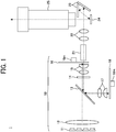
- FIG. 1 is a schematic illustration of an example of an image projection apparatus according to a first embodiment of the present disclosure.
- the image projection apparatus 1 includes an illumination device 10, a light tunnel 21, a lens group 22, a mirror group 23, an image forming element 24, and a projection optical section 25.
- the illumination device 10 includes a light source 11, a condenser lens 12, a wavelength-selective polarization splitter 13, a quarter wavelength plate 14, a first lens group 15, a color wheel 16, a second lens group 17, and a phosphor wheel 18.
- the illumination device 10 is designed to sequentially emit the blue, red, and green light rays toward the light tunnel 21 in the common direction (along the common optical path), in time divisions.
- the light source 11 emits a first light beam having a first linear polarization component.
- the light source 11 is a laser diode (LD) that emits a blue laser beam of a wavelength ⁇ B having a P polarization component (a P wave) are described.
- the wavelength ⁇ B is, for example, in the range of greater than 400 nanometer (nm) and less than 470 nm.
- the light source 11 is a light emitting diode (LED) that emits a blue light beam, or an organic electro luminescence (EL) device.
- the light source 11 is a combination of the LED and the organic EL.
- the light source 11 is any one of, e.g., a laser diode (LD), an LED, and an organic EL device for emitting light with an ultraviolet region wavelength.
- the light source 11 is a combination of these LD, LED, and organic EL device.
- the illumination device 10 includes a single light source 11 or a plurality of light sources 11. Further, between the light source 11 and the condenser lens 12, a coupling lens for guiding the laser beam emitted from the light source 11 to the condenser lens 12 as an approximately collimated light beam is provided.
- the blue laser light emitted from the light source 11 is used as first illumination light. Further, the blue laser light emitted from the light source 11 is used as excitation light that causes fluorescence in the phosphor wheel 18.
- the blue laser light emitted from the light source 11 passes through the condenser lens 12 and is directed to the wavelength-selective polarization splitter 13 as an approximately collimated light beam.
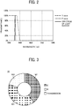
- the wavelength-selective polarization splitter 13 is, for example, an optical-path switcher that has spectral transmittance characteristics as illustrated in FIG. 2 .
- the wavelength-selective polarization splitter 13 has characteristics that transmits a P wave therethrough and fails to transmit an S wave (reflect the S wave) of the wavelength ⁇ B of the light emitted from the light source 11. As can be seen from the spectral transmittance characteristics of FIG. 2 , irrespective of whether it is the P wave or the S wave (regardless of polarization characteristics), light having a wavelength of approximately 500 nm or greater is reflected by the wavelength-selective polarization splitter 13. For example, a polarization beam splitter is used as the wavelength-selective polarization splitter 13.
- the P-wave blue laser light having entered the wavelength-selective polarization splitter 13 passes through the wavelength-selective polarization splitter 13, and is directed to the quarter wavelength plate 14 as a polarization converter that changes the linearly polarized light into the circular polarized light and vice versa.
- the light transmitted through the quarter wavelength plate 14 changes from P-wave (P-polarized light) to circularly polarized light, and passes through the first lens group 15, entering the color wheel 16 as a wavelength selector.
- the polarization converter is not limited to the quarter wavelength plate, and may be, for example, a product obtained by forming an oblique deposited film, such as Ta 205, on an incident surface of any lens that constitutes the first lens group 15.
- the oblique evaporated film is a film obtained by the process in which a deposition target is disposed obliquely relative to a direction of fly of deposition material (orientation of a deposition source), and the deposition material is deposited obliquely relative to a normal line of a certain surface of the deposition target.
- the first lens group 15 is constituted by combining, for example, a biconvex lens and a plano-convex lens as appropriate.
- the first lens group 15 serves to converge the approximately collimated light beam into a spot on the color wheel 16.
- the first lens group 15 further serves to collect and change light diverging from the color wheel 16 into a substantially parallel light beam (approximately collimated light beam).
- FIG. 3 is an enlarged plan view of the color wheel 16 according to the first embodiment when viewed from an incident side of the color wheel 16.
- the color wheel 16 according to the present embodiment has a configuration in which a disk-shaped member is divided into a plurality of fan-shaped areas (segments). Specifically, the color wheel 16 is divided into three fan-shaped areas (segments) of a red (R) area 161, a green (G) area 162, and a transmissive area 163.
- the color wheel 16 has, for example, spectral transmittance characteristics as illustrated in FIG. 4 .
- the red (R) area 161 is an area in which a filter that transmits red light is formed. As illustrated in FIG. 4 , light in a wavelength range of approximately 600 nm or greater is transmitted through the red (R) area 161, and light in the other wavelength range is reflected by the red (R) area 161.
- the green (G) area 162 is an area in which a filter that transmits green light is formed. As illustrated in FIG. 4 , light in a wavelength range of approximately 500 nm to 580 nm is transmitted through the green (G) area 162, and light in the other wavelength range is reflected by the green (G) area 162.
- the transmissive area 163 transmits light in all wavelength ranges therethrough.
- the transmissive area 163 is, for example, a transparent glass or a transparent diffusion plate.
- the transmissive area 163 is configured to have an opening.
- the diffuser plate has a structure in which a large number of projections or depressions having different sizes are formed on the surface. With the configuration that the transmissive area 163 is a diffuser plate for diffusing light, nonuniformity in blue light and speckles, which are to appear in, e.g., a screen, are reduced.
- the color wheel 16 includes a drive unit 16m, such as a stepping motor for rotating the color wheel 16, on the axis of the color wheel 16.
- a drive unit 16m such as a stepping motor for rotating the color wheel 16, on the axis of the color wheel 16.
- the color wheel 16 as a wavelength selector rotates at a predetermined timing with a drive of the drive unit 16m, the incident position of light coming from the first lens group 15 is switched between three areas (segments): the red (R) area 161, the green (G) area 162, and the transmissive area 163.
- the color wheel 16 temporally switches the area (segment) between the three areas 161, 162, and 163 to be placed in the optical path of the blue laser light and the fluorescence.
- whether the light incident on the color wheel 16 passes through the color wheel 16 or is reflected by the color wheel 16 is determined by the wavelength of the light condensed by the first lens group 15 and the area (segment) selectively arranged at the incident position of the light from the first lens group 15.
- the blue laser light entering the color wheel 16 passes through the color wheel 16 to become blue illumination light, entering the light tunnel 21. Since the blue illumination light transmitted through the color wheel 16 is circularly polarized light, it is possible to reduce speckle appearing on, e.g., a screen.
- transmissive area 163 is a representative example of a first area according to the embodiment of the present disclosure
- blue illumination light is a representative example of first illumination light according to the embodiments of the present disclosure.
- the blue laser light entering the color wheel 16 is reflected by the color wheel 16. Subsequently, the blue laser light reflected by the color wheel 16 passes through the first lens group 15, entering the quarter wavelength plate 14.
- the light transmitted through the quarter wavelength plate 14 changes from circularly polarized light to the S wave (S polarized light), and enters the wavelength-selective polarization splitter 13. Note that the S polarized light component is a component orthogonal to the P polarized light component.
- the S-wave blue laser light entering the wavelength-selective polarization splitter 13 is reflected by the wavelength-selective polarization splitter 13 and passes through the second lens group 17, entering the phosphor wheel 18. That is, the wavelength-selective polarization splitter 13 guides S-wave (S-polarized light) light to the phosphor wheel 18.
- the second lens group 17 is constituted by combining, for example, a biconvex lens and a plano-convex lens as appropriate.
- the second lens group 17 serves to converge the approximately collimated light beam into a spot on the phosphor wheel 18.
- the second lens group 17 further serves to collect and change light diverging from the phosphor wheel 18 into a substantially parallel light beam (approximately collimated light beam).
- FIG. 5 is an enlarged plan view of the phosphor wheel 18 according to the first embodiment when viewed from an incident side of the color wheel 16.
- the phosphor wheel 18 used in the present embodiment is a fluorescence generator in which a yellow fluorescent material 181 is formed in a disc-like member along the direction of rotation of a flat plate.
- the yellow fluorescent material 181 generates yellow fluorescence having a longer wavelength than the blue laser light with the blue laser light as the excitation light.
- the phosphor wheel 18 includes a drive unit 18m, such as a stepping motor for rotating the phosphor wheel 18, provided on the axis of the phosphor wheel 18.
- the phosphor wheel 18 may not be movable because a single-color yellow fluorescent material 181 is formed on substantially the entire surface of the phosphor wheel 18. This configuration reduces the size of the phosphor wheel 18 to any shape while reducing the cost because the drive unit 18 m is not used. In addition, since the phosphor wheel 18 does not rotate, noise is reduced.
- the yellow fluorescent material 181 With the blue laser light incident on the phosphor wheel 18 as excitation light, the yellow fluorescent material 181 generates yellow fluorescence.
- the yellow fluorescence passes through the second lens group 17 and is directed to the wavelength-selective polarization splitter 13.
- the yellow fluorescence is reflected by the wavelength-selective polarization splitter 13 and is directed to the quarter wavelength plate 14 because the yellow fluorescence has a wavelength of 500 nm or greater. Subsequently, the yellow fluorescence passes through the quarter wavelength plate 14 and the first lens group 15, entering the color wheel 16.
- the yellow fluorescence entering the color wheel 16 passes through the color wheel 16.
- the yellow fluorescence entering the color wheel 16 passes through the color wheel 16 to become red illumination light, entering the light tunnel 21.
- the green (G) area 162 is disposed at the incident position of the light coming from the first lens group 15, the yellow fluorescence entering the color wheel 16 passes through the color wheel 16 to become green illumination light, entering the light tunnel 21.
- red (R) area 161 and the green (G) area 162 are representative examples of a second area according to the embodiment of the present disclosure, and the red illumination light and the green illumination light are representative examples of second illumination light according to the embodiments of the present disclosure.
- the light tunnel 21 is a tubular member having a hollow interior. Each illumination light entering the light tunnel 21 repeats reflection inside the light tunnel 21, so that the illuminance distribution becomes uniform at the exit of the light tunnel 21. That is, the light tunnel 21 serves as an illuminance uniforming unit to reduce unevenness in intensity (light amount) of each illumination light. In some embodiments, any other component, such as a fly-eye lens, is used as the illuminance uniforming unit, instead of the light tunnel 21.
- Each illumination light of which the illuminance distribution has been uniformed through the light tunnel 21 is relayed to the third lens group 22, and is reflected by the mirror group 23, illuminating the image forming element 24.
- the image forming element 24 is an element that forms a color projection image with each illumination light by adjusting gradation for each pixel.
- the image forming element 24 is, for example, a digital micromirror device (DMD).
- the DMD has micromirrors on a pixel-by-pixel basis, each micromirror maintaining either one of two different angles.
- each micromirror of the DMD has an angle (ON state) at which each illumination light is reflected toward the projection optical section 25 and an angle (OFF state) at which each illumination light is reflected toward the internal absorber so as not to travel to an outside of the image projection apparatus 1.
- This allows controlling light to be projected for each pixel for display.
- the DMD is capable of expressing the gradation for each pixel to be displayed by adjusting the time ratio of each micromirror at the ON state, using the pulse width modulation method (PWM method).
- the image forming element 24 is not limited to the DMD, but any element capable of forming a color projection image using each illumination light from the illumination device 10 may be used.
- any element capable of forming a color projection image using each illumination light from the illumination device 10 may be used.
- liquid crystal is used.
- the image forming element 24 is irradiated with red, green, and blue illumination light in a time-division manner at the image generation timing in the image forming element 24.
- the illumination light passes through the projection optical section 25 and is projected onto, e.g., a screen. Then, using the afterimage phenomenon of the eye, a color image is visually recognized on, e.g., a screen.
- the light tunnel 21, the third lens group 22, and the mirror group 23 are representative examples of the optical path forming section according to the embodiments of the present disclosure.
- the image forming element 24 is disposed on the optical path defined by the optical path forming section.
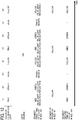
- the light source 11 is turned on (ON) while the red illumination light, the green illumination light, and the blue illumination light are temporally taken out in turn.
- the red (R) area 161 is set at the incident position of the light from the first lens group 15. Accordingly, the blue laser light is reflected by the color wheel 16, and passes through the optical system as described with referring to FIG. 1 , entering the phosphor wheel 18.
- the yellow fluorescent material 181 to generate yellow fluorescence, and the generated yellow fluorescence passes through the optical system as described above with referring to FIG. 1 , entering the color wheel 16 again (for the second time).
- the red (R) area 161 remains disposed at the incident position of the light from the first lens group 15 in the color wheel 16. Accordingly, the red fluorescence having entered the color wheel 16 passes through the color wheel 16 and becomes the red illumination light, entering the light tunnel 21 as the red illumination light.
- the green (G) area 162 is set at the incident position of the light from the first lens group 15 on the color wheel 16. Accordingly, the blue laser light is reflected by the color wheel 16, and passes through the optical system as described with referring to FIG. 1 , entering the phosphor wheel 18.
- the transmissive area 163 is set at the incident position of the light from the first lens group 15 on the color wheel 16. Accordingly, the blue laser light passes through the color wheel 16 and becomes the blue illumination light, entering the light tunnel 21 as the blue illumination light. In this case, since the blue laser light emitted from the light source 11 enters and passes through the color wheel 16 as is, for the first time. Thus, the blue laser light does not enter the phosphor wheel 18 (indicated by "-" in (3) of FIG. 6 ).
- the control device includes, for example, a central processing unit (CPU), a read only memory (ROM), and a random access memory (RAM) as hardware.
- the control device is implemented by software according to a program preliminarily stored in the ROM, using the RAM as a work memory, so as to control the light source 11, the color wheel 16, the phosphor wheel 18, and the image forming element 24.
- the control device is disposed in the interior of the image projection apparatus 1.
- the quarter wavelength plate 14 is disposed on the optical path between the wavelength-selective polarization splitter 13 and the color wheel 16.
- the image projection apparatus 1 includes a first optical path through which the blue laser light emitted from the light source 11 sequentially passes through the wavelength-selective polarization splitter 13, the quarter wavelength plate 14, and the color wheel 16, and travels to the light tunnel 21.
- the image projection apparatus 1 further includes a second optical path.
- the blue laser light emitted from the light source 11 sequentially passes through the wavelength-selective polarization splitter 13 and the quarter wavelength plate 14, and is reflected by the color wheel 16 to travel back to the quarter wavelength plate 14.
- the blue laser light is converted into S-polarized light in the quarter wavelength plate 14 and passes through the wavelength-selective polarization splitter 13, traveling to the phosphor wheel 18.
- the phosphor wheel 18 having received the light generates fluorescence.
- the generated fluorescence travels through the wavelength-selective polarization splitter 13, the quarter wavelength plate 14, and the color wheel 16, and is directed to the light tunnel 21.
- the optical path is switched between the first optical path and the second optical path.
- This configuration allows the optical path from the wavelength-selective polarization splitter 13 to the color wheel 16 to be common therebetween. In other words, it is unnecessary to design so as to bypass one of the two optical paths as in the comparative example, and the illumination device 10 can be downsized.
- measurements are conducted on the optical components to prevent a degradation in image quality. This will be described with reference to FIGs. 7 to 9 .
- the blue laser light is reflected for the first time by the segment (the red (R) area 161 or the green (G) area 162) of the color wheel 16, so as to form red color illumination light in (1) of FIG. 6 or green color illumination light in (2) of FIG. 6 .
- the reflectance in each of the red (R) area 161 and the green (G) area 162 is not 100% due to the characteristics of the component in actuality. In fact, slight light passes through the color wheel 16 and enters the light tunnel 21.
- an optical component as a part of the optical system is designed to have the optical characteristics such that an average reflectance or an average transmittance of the wavelengths of 400 nm or more and less than 500 nm is lower than an average reflectance or an average transmittance of the wavelengths of 500 nm or more and less than 800 nm.
- a mirror having the optical characteristics (reflectance spectrum) of FIG. 8A is disposed at any position in the optical path between the exit end of the wavelength-selective polarization splitter 13 and the exit end of the projection optical section 25, a mirror having the optical characteristics (reflectance spectrum) of FIG. 8A is disposed. More specifically, such a mirror has the optical characteristics that an average reflectance of the wavelengths of not less than 400 nm and less than 500 nm is lower than an average reflectance of the wavelengths of not less than 500 nm and less than 800 nm. In this case, any mirror constituting the mirror group 23 in FIG. 1 has the optical characteristics as illustrated in FIG. 8A . Alternatively, in some embodiments, any new mirror is added to the optical system. As illustrated in FIG. 8A , in the comparative embodiment, an optical component in which an average reflectance of the wavelength of 400 nm or more and less than 800 nm is substantially constant (substantially 100%) has been used.
- a lens having the optical characteristics (transmittance spectrum) of FIG. 8B is disposed at any position in the optical path between the exit end of the wavelength-selective polarization splitter 13 and the exit end of the projection optical section 25, a lens having the optical characteristics (transmittance spectrum) of FIG. 8B is disposed. More specifically, such a mirror has the optical characteristics that an average transmittance of the wavelengths of not less than 400 nm and less than 500 nm is lower than an average transmittance of the wavelengths of not less than 500 nm and less than 800 nm. In this case, any lens constituting the first lens group 15 or the third lens group 22 in FIG. 1 has the optical characteristics as illustrated in FIG. 8B . Alternatively, in some embodiments, any new lens is added to the optical system. As illustrated in FIG. 8B , in the comparative embodiment, an optical component in which an average transmittance of the wavelength of 400 nm or more and less than 800 nm is substantially constant (substantially 100%) has been used.
- both a mirror having the optical characteristics (reflectance spectrum) of FIG. 8A and a lens having the optical characteristics (transmittance spectrum) of FIG. 8B is disposed.
- the mirror having the reflectance spectrum of FIG. 8A has an average reflectance of the wavelengths of 400 nm or more and less than 500 nm that is lower than an average reflectance of the wavelengths of 500 nm or more and less than 800 nm.
- the lens having the transmittance spectrum of FIG. 8B has an average transmittance of the wavelengths of 400 nm or more and less than 500 nm that is lower than an average transmittance of the wavelengths of 500 nm or more and less than 800 nm.
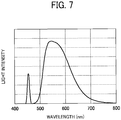
- the mirror having the optical characteristics of FIG. 8A or the lens having the optical characteristics of FIG. 8B at any position in the optical path between the exit end of the wavelength-selective polarization splitter 13 and the exit end of the projection optical section 25, the blue light near the wavelength of 450 nm that is unintentionally mixed with light, such as yellow light, is weakened as illustrated in FIG. 9 , thereby providing a color change in an appropriate range, thus preventing image quality degradation.
- any optical component on a light-source side of the color wheel 16 has the optical characteristics of FIG. 8A or FIG. 8B , the blue light irradiated to the phosphor wheel 18 is weakened, thereby unsuccessfully reducing the brightness obtained. Therefore, any optical component having the optical characteristics of FIG. 8A or FIG. 8B is arranged in the optical system after the color wheel 16 (on the side of the projection optical section 25 from the color wheel 16).
- the image forming element 24 is preferably cooled so as to have a constant temperature.
- the optical component having the optical characteristics of FIG. 8A or FIG. 8B in the optical system on the side of the light source 11 from the image forming element 24, the intensity of light irradiated to the image forming element 24 is reduced, thereby advantageously facilitating cooling down the image forming element 24.
- the configuration that the optical components as a part of the optical system has the optical characteristics of FIG. 8A or FIG. 8B prevents or reduces image quality deterioration in the image projection apparatus according to each embodiment same as in the image projection apparatus 1.
- the optical characteristics (reflectance spectrum) of FIG. 8A is only an example, and may have optical characteristics (reflectance spectrum) different from those of FIG. 8A as long as an average reflectance of the wavelengths of not less than 400 nm and less than 500 nm is lower than an average reflectance of the wavelengths of not less than 500 nm and less than 800 nm.
- the optical characteristic (transmittance spectrum) of FIG. 8B is an example, and if the average transmittance of 400 nm or more and may have optical characteristics (transmittance spectrum) different from those of FIG. 8B as long as an average reflectance of the wavelengths of not less than 400 nm and less than 500 nm is lower than an average reflectance of the wavelengths of not less than 500 nm and less than 800 nm.
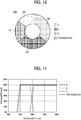
- FIG. 10 is an enlarged plan view of the color wheel 16 according to the second embodiment when viewed from an incident side of the color wheel 16.
- a color wheel 16A is used in the illumination device 10, instead of the color wheel 16.
- the color wheel 16A according to the present embodiment has a configuration in which a disk-shaped member is divided into a plurality of fan-shaped areas (segments). Specifically, the color wheel 16A is divided into four fan-shaped areas (segments) of a red (R) area 161, a green (G) area 162, a transmissive area 163, and a yellow (Y) area 164.
- the color wheel 16A differs from the color wheel 16 (see FIG. 3 ) in that the color wheel 16A further includes the yellow (Y) area 164.
- the color wheel 16A has, for example, spectral transmittance characteristics as illustrated in FIG. 11 .
- the spectral transmittance characteristics of the red (R) area 161, the green (G) area 162, and the transmissive area 163 are the same as in the color wheel 16 of FIG. 4 .
- the yellow (Y) area 164 is an area in which a filter that transmits yellow light is formed. As illustrated in FIG. 11 , light in a wavelength range of approximately 500 nm or greater is transmitted through the yellow (Y) area 164, and light in the other wavelength range is reflected by the yellow (Y) area 164.
- the incident position of light coming from the first lens group 15 is switched between four areas (segments): the red (R) area 161, the green (G) area 162, the transmissive area 163, and the yellow (Y) area 164.
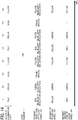
- the light source 11 is turned on (ON) while the red illumination light, the green illumination light, the blue illumination light, and the yellow illumination light are temporally taken out in turn.
- the timing chart of a period in which red illumination light is obtained in (1) of FIG. 12 , a period in which green illumination light is obtained in (2) of FIG. 12 , and a period in which blue illumination light is obtained in (3) of FIG. 12 is the same as that of (1) through (3) of FIG. 6 .
- the yellow (Y) area 164 is set at the incident position of the light from the first lens group 15 on the color wheel 16A. Accordingly, the blue laser light is reflected by the color wheel 16A, and passes through the optical system as described with referring to FIG. 1 , entering the phosphor wheel 18.
- the illumination device 11 has the configuration in which the color wheel 16A further includes the yellow (Y) area 164 to obtain the yellow illumination light. Taking out the yellow illumination light increases the brightness of the image projected onto, e.g., a screen.
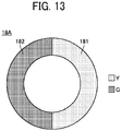
- FIG. 13 is an enlarged plan view of the phosphor wheel 18 according to the third embodiment when viewed from an incident side of the phosphor wheel 18.
- the phosphor wheel 18A used in the present embodiment is a disk-shaped member divided into a plurality of areas that emit different fluorescence.
- the phosphor wheel 18A is driven to rotate such that an area to which light from the wavelength-selective polarization splitter 13 is irradiated is sequentially changed.
- the phosphor wheel 18A has two divided fan-shaped areas (segments): an area in which a yellow fluorescent material 181 emitting yellow (Y) fluorescence is formed and an area in which a green fluorescent material 182 emitting green (G) fluorescence is formed.
- the phosphor wheel 18A differs from the phosphor wheel 18 (see FIG. 5 ) in that the green fluorescent material 182 is formed in the phosphor wheel 18A.
- the incident position of the light from the second lens group 17 is switched between areas (segments): the area in which the yellow fluorescent material 181 is formed and the area in which the green fluorescent material 182 is formed.
- the light source 11 is turned on (ON) while the red illumination light, the green illumination light, the blue illumination light, and the yellow illumination light are temporally taken out in turn.
- the red (R) area 161 is set at the incident position of the light from the first lens group 15. This configuration allows the blue laser light to be reflected by the color wheel 16A, and passes through a certain optical system as described with referring to FIG. 1 , entering the phosphor wheel 18A.
- the yellow fluorescent material 181 is disposed at the incident position of light from the second lens group 17 in the phosphor wheel 18A. This allows the yellow fluorescent material 181 to generate yellow fluorescence, and the generated yellow fluorescence passes through the optical system as described above with referring to FIG. 1 , entering the color wheel 16A again (for the second time). At this time, the red (R) area 161 remains disposed at the incident position of the light from the first lens group 15. Accordingly, the red fluorescence having entered the color wheel 16A passes through the color wheel 16A and becomes the red illumination light, entering the light tunnel 21 as the red illumination light.
- the green (G) area 162 is set at the incident position of the light from the first lens group 15 on the color wheel 16A. This configuration allows the blue laser light to be reflected by the color wheel 16A, and passes through a certain optical system as described with referring to FIG. 1 , entering the phosphor wheel 18A.
- the green fluorescent material 182 is disposed at the incident position of light from the second lens group 17 in the phosphor wheel 18A. Accordingly, the green fluorescent material 182 generates green fluorescence, and the generated green fluorescence passes through the optical system as described above with referring to FIG. 1 , entering the color wheel 16A again (for the second time). At this time, the green (G) area 162 remains disposed at the incident position of the light from the first lens group 15 in the color wheel 16A. Accordingly, the green fluorescence having entered the color wheel 16A passes through the color wheel 16A and becomes the green illumination light, entering the light tunnel 21 as the green illumination light.
- the transmissive area 163 is set at the incident position of the light from the first lens group 15 on the color wheel 16A. Accordingly, the blue laser light passes through the color wheel 16A and becomes the blue illumination light, entering the light tunnel 21 as the blue illumination light. In this case, since the blue laser light emitted from the light source 11 enters and passes through the color wheel 16A as is, for the first time. Thus, the blue laser light does not enter the phosphor wheel 18A (indicated by "-" in (3) of FIG. 14 ).
- the yellow (Y) area 164 is set at the incident position of the light from the first lens group 15 on the color wheel 16A. Accordingly, the blue laser light is reflected by the color wheel 16A, and passes through the optical system as described with referring to FIG. 1 , entering the phosphor wheel 18A.
- the yellow fluorescent material 181 is disposed at the incident position of light from the second lens group 17 in the phosphor wheel 18A. This allows the yellow fluorescent material 181 to generate yellow fluorescence, and the generated yellow fluorescence passes through the optical system as described above with referring to FIG. 1 , entering the color wheel 16A again (for the second time). At this time, the yellow (Y) area 164 remains disposed at the incident position of the light from the first lens group 15 in the color wheel 16A. Accordingly, the yellow fluorescence having entered the color wheel 16A passes through the color wheel 16A and becomes the yellow illumination light, entering the light tunnel 21 as the yellow illumination light. Thereafter, (1) through (4) of FIG. 14 are repeated in chronological order.
- the red, green, blue, and yellow illumination light are obtained in a time-division manner.
- the phosphor wheel 18A provided with the area to generate yellow fluorescence and the area to generate green fluorescence, the brightness of an image projected on, e.g., a screen is enhanced.
- the green color fluorescence is used to transmit the green color light through the color wheel as in the present embodiment, a small amount of light is sometimes discarded in the color wheel to adjust the color. However, the amount of discarded light is smaller than the case in which the green color light is made from the yellow fluorescence in the color wheel.
- the brightness of an image projected onto, e.g., a screen is enhanced in the case in which the green color light is transmitted through the color wheel using the green fluorescence.
- the heat generation of the color wheel is also reduced.
- the green color light is made from the yellow fluorescence in the color wheel as in the first and second embodiments.
- FIG. 15 is an enlarged plan view of the phosphor wheel 18 according to the fourth embodiment when viewed from an incident side of the phosphor wheel 18.
- the phosphor wheel 18B used in the present embodiment is a disk-shaped member divided into a plurality of areas that emit different fluorescence.
- the phosphor wheel 18B is driven to rotate such that an area to which light from the wavelength-selective polarization splitter 13 is irradiated is sequentially changed.
- the phosphor wheel 18B has three divided fan-shaped areas (segments): an area in which a yellow fluorescent material 181 emitting yellow (Y) fluorescence is formed, an area in which a green fluorescent material 182 emitting green (G) fluorescence is formed, and an area in which a red fluorescent material 183 emitting red (R) fluorescence is formed.
- the phosphor wheel 18B differs from the phosphor wheel 18A (see FIG. 13 ) in that the red fluorescent material 183 is formed in the phosphor wheel 18B.
- the incident position of the light from the second lens group 17 is switched between areas (segments), the area in which the yellow fluorescent material 181 is formed, the area in which the green fluorescent material 182 is formed, and the area in which the red fluorescent material 183 is formed.
- the light source 11 is turned on (ON) while the red illumination light, the green illumination light, the blue illumination light, and the yellow illumination light are temporally taken out in turn.
- the red (R) area 161 is set at the incident position of the light from the first lens group 15. This configuration allows the blue laser light to be reflected by the color wheel 16A, and passes through a certain optical system as described with referring to FIG. 1 , entering the phosphor wheel 18B.
- the red fluorescent material 183 is disposed at the incident position of light from the second lens group 17 in the phosphor wheel 18B. This allows the red fluorescent material 183 to generate red fluorescence, and the generated red fluorescence passes through the optical system as described above with referring to FIG. 1 , entering the color wheel 16A again (for the second time). At this time, the red (R) area 161 remains disposed at the incident position of the light from the first lens group 15. Accordingly, the red fluorescence having entered the color wheel 16A passes through the color wheel 16A and becomes the red illumination light, entering the light tunnel 21 as the red illumination light.
- the timing chart of a period in which green illumination light is obtained in (2) of FIG. 16 , a period in which blue illumination light is obtained in (3) of FIG. 16 , and a period in which yellow illumination light is obtained in (4) of FIG. 16 is the same as that of (2) through (4) of FIG. 14 . Thereafter, (1) through (4) of FIG. 16 are repeated in chronological order.
- the red, green, blue, and yellow illumination light are obtained in a time-division manner.
- the phosphor wheel 18B provided with the area to generate yellow fluorescence, the area to generate green fluorescence, and the area to generate red fluorescence, the brightness of an image projected on, e.g., a screen is enhanced.
- the red color fluorescence is used to transmit the red color light through the color wheel as in the present embodiment, a small amount of light is sometimes discarded in the color wheel to adjust the color. However, the amount of discarded light is smaller than the case in which the red color light is made from the yellow fluorescence in the color wheel.
- the brightness of an image projected onto, e.g., a screen is enhanced in the case in which the red color light is transmitted through the color wheel using the red fluorescence.
- the heat generation of the color wheel is also reduced.
- the red color light is made from the yellow fluorescence in the color wheel as in the first through third embodiments.
- FIG. 17 is a schematic illustration of an example of an image projection apparatus 1A according to a fifth embodiment of the present disclosure.
- the image projection apparatus 1A includes an illumination device 10A, a light tunnel 21, a lens group 22, a mirror group 23, an image forming element 24, and a projection optical section 25.
- the illumination device 10A differs from the illumination device 10 in the arrangement of the optical system and in that the illumination device 10A includes a wavelength-selective polarization splitter 13A instead of the wavelength-selective polarization splitter 13.
- the blue laser light emitted from the light source 11 passes through the condenser lens 12 and is directed to the wavelength-selective polarization splitter 13A.
- the wavelength-selective polarization splitter 13A has, for example, spectral transmittance characteristics as illustrated in FIG. 18 .
- the wavelength-selective polarization splitter 13A has a characteristic of reflecting the P wave and transmitting the S wave. As can be seen from the spectral transmittance characteristics of FIG. 18 , irrespective of whether it is the P wave or the S wave (regardless of polarization characteristics), light having a wavelength of approximately 500 nm or greater is reflected by the wavelength-selective polarization splitter 13A.
- a polarization beam splitter is used as the wavelength-selective polarization splitter 13A.
- the P-wave blue laser light having entered the wavelength-selective polarization splitter 13A passes through the wavelength-selective polarization splitter 13A, and is directed to the quarter wavelength plate 14.
- the light transmitted through the quarter wavelength plate 14 becomes circularly polarized light, is collected by the first lens group 15, entering the color wheel 16.
- the transmissive area 163 At the timing when the transmissive area 163 is disposed at the incident position of the light coming from the first lens group 15, the blue laser light entering the color wheel 16 passes through the color wheel 16 to become blue illumination light, entering the light tunnel 21.
- the blue laser light entering the color wheel 16 is reflected by the color wheel 16. Subsequently, the blue laser light reflected by the color wheel 16 passes through the first lens group 15, entering the quarter wavelength plate 14.
- the light transmitted through the quarter wavelength plate 14 changes from circularly polarized light to the S wave (S polarized light), and enters the wavelength-selective polarization splitter 13A.
- the S-wave blue laser light having entered the wavelength-selective polarization splitter 13A passes through the wavelength-selective polarization splitter 13A, and is collected by the second lens group 17, entering the phosphor wheel 18.
- the yellow fluorescent material 181 With the blue laser light incident on the phosphor wheel 18 as excitation light, the yellow fluorescent material 181 generates yellow fluorescence.
- the yellow fluorescence passes through the second lens group 17 and is directed to the wavelength-selective polarization splitter 13A.
- the yellow fluorescence passes through the wavelength-selective polarization splitter 13A (see FIG. 18 ), and further passes through the quarter wavelength plate 14 and the first lens group 15, entering the color wheel 16.
- the other characteristics in the optical path after the color wheel 16 are the same as in the image projection apparatus 1 in FIG. 1 .
- the optical system is arranged such that the blue laser light emitted from the light source 11 is reflected by the wavelength-selective polarization splitter 13A.
- the distance between the light source 11 and the color wheel 16 has to be separated to some extent (to condense the light), which increases the lateral width of the optical system.
- the light source 11 and the color wheel 16 are not opposed to each other, which allows a reduction in the lateral width of the optical system. That is, the illumination device 10A in FIG. 17 is further reduced in size as compared to the illumination device 10 in FIG. 1 .
- FIG. 19 is a schematic illustration of an example of an image projection apparatus 1A according to a sixth embodiment of the present disclosure.
- the image projection apparatus 1B includes an illumination device 10B, a light tunnel 21, a lens group 22, a mirror group 23, an image forming element 24, and a projection optical section 25.
- the illumination device 10B differs from the illumination device 10 in the arrangement of the optical system and in that the illumination device 10B includes a wavelength-selective polarization splitter 13A instead of the wavelength-selective polarization splitter 13.
- the blue laser light emitted from the light source 11 passes through the condenser lens 12 and is directed to the wavelength-selective polarization splitter 13A.
- the wavelength-selective polarization splitter 13A has, for example, spectral transmittance characteristics as illustrated in FIG. 18 .
- the P-wave blue laser light having entered the wavelength-selective polarization splitter 13A passes through the wavelength-selective polarization splitter 13A, and is directed to the quarter wavelength plate 14.
- the light transmitted through the quarter wavelength plate 14 becomes circularly polarized light, is condensed by the first lens group 15, and enters the color wheel 16.
- the transmissive area 163 At the timing when the transmissive area 163 is disposed at the incident position of the light coming from the first lens group 15, the blue laser light entering the color wheel 16 passes through the color wheel 16 to become blue illumination light, entering the light tunnel 21.
- the blue laser light entering the color wheel 16 is reflected by the color wheel 16. Subsequently, the blue laser light reflected by the color wheel 16 passes through the first lens group 15, entering the quarter wavelength plate 14. The light transmitted through the quarter wavelength plate 14 changes from circularly polarized light to the S wave (S polarized light), and enters the wavelength-selective polarization splitter 13.
- the S-wave blue laser light entering the wavelength-selective polarization splitter 13 is reflected by the wavelength-selective polarization splitter 13 and collected by the lens group 17, entering the phosphor wheel 18.
- the yellow fluorescent material 181 With the blue laser light incident on the phosphor wheel 18 as excitation light, the yellow fluorescent material 181 generates yellow fluorescence.
- the yellow fluorescence passes through the second lens group 17 and is directed to the wavelength-selective polarization splitter 13.
- the yellow fluorescence is reflected by the wavelength selective polarization splitter 13 (see FIG. 2 ), and passes through the quarter wavelength plate 14 and the first lens group 15, entering the color wheel 16.
- the other characteristics in the optical path after the color wheel 16 are the same as in the image projection apparatus 1 in FIG. 1 .
- the image projection apparatus 1B includes a wavelength-selective polarization splitter 13 as an optical-path switcher and a wavelength-selective polarization splitter 13A.
- the wavelength-selective polarization splitter 13 transmits first light having the P polarization component and reflects second light having the S polarization component and fluorescence.
- the wavelength-selective polarization splitter 13A reflects the first light having the P polarization component and transmits the second light having the S polarization component and the fluorescence.
- wavelength-selective polarization splitter 13 is a representative example of a first polarization splitter according to the embodiments of the present disclosure
- wavelength-selective polarization splitter 13A is a representative example of a second polarization splitter according to the embodiments of the present disclosure.
- the first linearly polarized light component of the light source 11 is an S-polarized light component.
- the transmission and reflection characteristics of P-polarized light and S-polarized light in the wavelength-selective polarization splitter 13 or 13A are reversed to each other.
- the illumination device 10A in FIG. 17 or the illumination device 10B in FIG. 19 includes the color wheel 16A, the phosphor wheel 18A or 18B used.
- the illumination device according to each embodiment is applicable in a project as an example of an image projection apparatus. However, no limitation is intended thereby.
- the illumination device according to each embodiment is applicable in, for example, a heads-up display (HUD) or a head mount display (HMD).
- HUD heads-up display
- HMD head mount display
- the present invention can be implemented in any convenient form, for example using dedicated hardware, or a mixture of dedicated hardware and software.
- the present invention may be implemented as computer software implemented by one or more networked processing apparatuses.
- the processing apparatuses can compromise any suitably programmed apparatuses such as a general purpose computer, personal digital assistant, mobile telephone (such as a WAP or 3G-compliant phone) and so on. Since the present invention can be implemented as software, each and every aspect of the present invention thus encompasses computer software implementable on a programmable device.
- the computer software can be provided to the programmable device using any conventional carrier medium (carrier means).
- the carrier medium can compromise a transient carrier medium such as an electrical, optical, microwave, acoustic or radio frequency signal carrying the computer code.
- transient medium is a TCP/IP signal carrying computer code over an IP network, such as the Internet.
- the carrier medium can also comprise a storage medium for storing processor readable code such as a floppy disk, hard disk, CD ROM, magnetic tape device or solid state memory device.
Landscapes
- Physics & Mathematics (AREA)
- General Physics & Mathematics (AREA)
- Engineering & Computer Science (AREA)
- Multimedia (AREA)
- Optics & Photonics (AREA)
- Projection Apparatus (AREA)
- Transforming Electric Information Into Light Information (AREA)
Applications Claiming Priority (1)
| Application Number | Priority Date | Filing Date | Title |
|---|---|---|---|
| JP2017032527A JP2018136506A (ja) | 2017-02-23 | 2017-02-23 | 照明装置、画像投射装置 |
Publications (2)
| Publication Number | Publication Date |
|---|---|
| EP3367162A1 true EP3367162A1 (de) | 2018-08-29 |
| EP3367162B1 EP3367162B1 (de) | 2020-04-15 |
Family
ID=61258155
Family Applications (1)
| Application Number | Title | Priority Date | Filing Date |
|---|---|---|---|
| EP18157814.7A Not-in-force EP3367162B1 (de) | 2017-02-23 | 2018-02-21 | Beleuchtungsvorrichtung und bildprojektionsvorrichtung |
Country Status (3)
| Country | Link |
|---|---|
| US (1) | US10139718B2 (de) |
| EP (1) | EP3367162B1 (de) |
| JP (1) | JP2018136506A (de) |
Cited By (1)
| Publication number | Priority date | Publication date | Assignee | Title |
|---|---|---|---|---|
| CN111766757A (zh) * | 2019-04-02 | 2020-10-13 | 中强光电股份有限公司 | 照明系统与投影装置 |
Families Citing this family (12)
| Publication number | Priority date | Publication date | Assignee | Title |
|---|---|---|---|---|
| JP5637274B2 (ja) * | 2012-12-26 | 2014-12-10 | 株式会社リコー | 光源装置及びこれを用いたプロジェクタ |
| CN106200237A (zh) * | 2016-09-09 | 2016-12-07 | 合肥鑫晟光电科技有限公司 | 荧光轮及投影仪 |
| CN110703552B (zh) * | 2018-07-10 | 2021-10-15 | 中强光电股份有限公司 | 照明系统以及投影装置 |
| CN209281140U (zh) * | 2018-12-17 | 2019-08-20 | 深圳光峰科技股份有限公司 | 光源改善装置 |
| JP7212843B2 (ja) | 2018-12-19 | 2023-01-26 | カシオ計算機株式会社 | 光源装置及び投影装置 |
| CN111381428B (zh) * | 2018-12-29 | 2022-03-04 | 深圳光峰科技股份有限公司 | 光源系统及投影装置 |
| CN114280880A (zh) * | 2020-09-28 | 2022-04-05 | 中强光电股份有限公司 | 照明系统及投影装置 |
| CN114488671B (zh) | 2020-10-26 | 2024-04-09 | 中强光电股份有限公司 | 投影装置以及照明系统 |
| CN215867492U (zh) * | 2021-08-27 | 2022-02-18 | 中强光电股份有限公司 | 照明装置及投影装置 |
| JP7571754B2 (ja) * | 2022-03-16 | 2024-10-23 | カシオ計算機株式会社 | 光源装置及び投影装置 |
| CN117850138A (zh) * | 2022-09-30 | 2024-04-09 | 深圳洛克创新科技有限公司 | 投影照明装置及投影设备 |
| US20250044675A1 (en) * | 2023-08-02 | 2025-02-06 | Texas Instruments Incorporated | System and method for optical architecture |
Citations (7)
| Publication number | Priority date | Publication date | Assignee | Title |
|---|---|---|---|---|
| JPS49736B1 (de) | 1968-02-26 | 1974-01-09 | ||
| JP2010237443A (ja) | 2009-03-31 | 2010-10-21 | Casio Computer Co Ltd | 光源装置及びプロジェクタ |
| EP2544048A1 (de) * | 2011-07-05 | 2013-01-09 | Ricoh Company, Ltd. | Beleuchtungsvorrichtung und Projektionsvorrichtung |
| US20130242534A1 (en) * | 2011-10-13 | 2013-09-19 | Texas Instruments Incorporated | Projector light source and system, including configuration for display of 3d images |
| JP2015028504A (ja) * | 2013-07-30 | 2015-02-12 | 株式会社リコー | 照明装置および投射表示装置 |
| US20150124431A1 (en) * | 2013-11-05 | 2015-05-07 | Panasonic Intellectual Property Management Co., Ltd. | Illumination apparatus |
| WO2015183053A1 (en) * | 2014-05-30 | 2015-12-03 | Lg Electronics Inc. | Optical device and image projection apparatus including the same |
Family Cites Families (2)
| Publication number | Priority date | Publication date | Assignee | Title |
|---|---|---|---|---|
| JP4429656B2 (ja) | 2003-08-04 | 2010-03-10 | 株式会社リコー | 画像投影装置および画像投影方法 |
| JP2018060127A (ja) * | 2016-10-07 | 2018-04-12 | ウシオ電機株式会社 | 光源装置 |
-
2017
- 2017-02-23 JP JP2017032527A patent/JP2018136506A/ja active Pending
-
2018
- 2018-02-09 US US15/892,703 patent/US10139718B2/en active Active
- 2018-02-21 EP EP18157814.7A patent/EP3367162B1/de not_active Not-in-force
Patent Citations (7)
| Publication number | Priority date | Publication date | Assignee | Title |
|---|---|---|---|---|
| JPS49736B1 (de) | 1968-02-26 | 1974-01-09 | ||
| JP2010237443A (ja) | 2009-03-31 | 2010-10-21 | Casio Computer Co Ltd | 光源装置及びプロジェクタ |
| EP2544048A1 (de) * | 2011-07-05 | 2013-01-09 | Ricoh Company, Ltd. | Beleuchtungsvorrichtung und Projektionsvorrichtung |
| US20130242534A1 (en) * | 2011-10-13 | 2013-09-19 | Texas Instruments Incorporated | Projector light source and system, including configuration for display of 3d images |
| JP2015028504A (ja) * | 2013-07-30 | 2015-02-12 | 株式会社リコー | 照明装置および投射表示装置 |
| US20150124431A1 (en) * | 2013-11-05 | 2015-05-07 | Panasonic Intellectual Property Management Co., Ltd. | Illumination apparatus |
| WO2015183053A1 (en) * | 2014-05-30 | 2015-12-03 | Lg Electronics Inc. | Optical device and image projection apparatus including the same |
Cited By (3)
| Publication number | Priority date | Publication date | Assignee | Title |
|---|---|---|---|---|
| CN111766757A (zh) * | 2019-04-02 | 2020-10-13 | 中强光电股份有限公司 | 照明系统与投影装置 |
| US11126074B2 (en) | 2019-04-02 | 2021-09-21 | Coretronic Corporation | Illumination system and projection apparatus |
| CN111766757B (zh) * | 2019-04-02 | 2021-10-29 | 中强光电股份有限公司 | 照明系统与投影装置 |
Also Published As
| Publication number | Publication date |
|---|---|
| JP2018136506A (ja) | 2018-08-30 |
| US10139718B2 (en) | 2018-11-27 |
| US20180239233A1 (en) | 2018-08-23 |
| EP3367162B1 (de) | 2020-04-15 |
Similar Documents
| Publication | Publication Date | Title |
|---|---|---|
| EP3367162B1 (de) | Beleuchtungsvorrichtung und bildprojektionsvorrichtung | |
| US8840253B2 (en) | Light source apparatus and image display apparatus using the same | |
| EP2544048B1 (de) | Beleuchtungsvorrichtung und Projektionsvorrichtung | |
| US9417511B2 (en) | Lighting device, projector including the same, and lighting method | |
| US9594296B2 (en) | Illumination device including a wavelength converter | |
| JP6238387B2 (ja) | 光源装置およびプロジェクタ | |
| US8562146B2 (en) | Light source device and image display apparatus | |
| JP6452172B2 (ja) | 照明装置、ホイール劣化検出方法及びプロジェクタ | |
| US11359793B2 (en) | Lighting apparatus and projection-type image display apparatus | |
| JP6759853B2 (ja) | 照明装置、画像投射装置 | |
| EP2990869A1 (de) | Lichtquellenvorrichtung und projektor mit lichtquellenvorrichtung | |
| CN104062837A (zh) | 光源装置和显示装置 | |
| JP2012008549A (ja) | 光源装置およびこれを用いた照明装置ならびに画像表示装置 | |
| KR20160019177A (ko) | 일체형 파장 변환 휠 및 컬러 휠이 구비된 프로젝션 장치 | |
| WO2014041636A1 (ja) | 照明光学装置、プロジェクタ、および照明光学装置の制御方法 | |
| JP2016166925A (ja) | 照明装置及び投射表示装置 | |
| KR100777907B1 (ko) | 칼라 영상투사장치의 조명광학계 |
Legal Events
| Date | Code | Title | Description |
|---|---|---|---|
| PUAI | Public reference made under article 153(3) epc to a published international application that has entered the european phase |
Free format text: ORIGINAL CODE: 0009012 |
|
| STAA | Information on the status of an ep patent application or granted ep patent |
Free format text: STATUS: REQUEST FOR EXAMINATION WAS MADE |
|
| 17P | Request for examination filed |
Effective date: 20180221 |
|
| AK | Designated contracting states |
Kind code of ref document: A1 Designated state(s): AL AT BE BG CH CY CZ DE DK EE ES FI FR GB GR HR HU IE IS IT LI LT LU LV MC MK MT NL NO PL PT RO RS SE SI SK SM TR |
|
| AX | Request for extension of the european patent |
Extension state: BA ME |
|
| REG | Reference to a national code |
Ref country code: DE Ref legal event code: R079 Ref document number: 602018003688 Country of ref document: DE Free format text: PREVIOUS MAIN CLASS: G03B0021140000 Ipc: G02B0026000000 |
|
| RIC1 | Information provided on ipc code assigned before grant |
Ipc: G03B 21/16 20060101ALI20190729BHEP Ipc: G02B 27/28 20060101ALI20190729BHEP Ipc: G02B 26/00 20060101AFI20190729BHEP Ipc: G03B 21/14 20060101ALI20190729BHEP Ipc: G03B 33/08 20060101ALI20190729BHEP Ipc: G03B 21/20 20060101ALI20190729BHEP |
|
| GRAP | Despatch of communication of intention to grant a patent |
Free format text: ORIGINAL CODE: EPIDOSNIGR1 |
|
| STAA | Information on the status of an ep patent application or granted ep patent |
Free format text: STATUS: GRANT OF PATENT IS INTENDED |
|
| INTG | Intention to grant announced |
Effective date: 20191114 |
|
| RAP1 | Party data changed (applicant data changed or rights of an application transferred) |
Owner name: RICOH COMPANY, LTD. |
|
| GRAS | Grant fee paid |
Free format text: ORIGINAL CODE: EPIDOSNIGR3 |
|
| GRAA | (expected) grant |
Free format text: ORIGINAL CODE: 0009210 |
|
| STAA | Information on the status of an ep patent application or granted ep patent |
Free format text: STATUS: THE PATENT HAS BEEN GRANTED |
|
| AK | Designated contracting states |
Kind code of ref document: B1 Designated state(s): AL AT BE BG CH CY CZ DE DK EE ES FI FR GB GR HR HU IE IS IT LI LT LU LV MC MK MT NL NO PL PT RO RS SE SI SK SM TR |
|
| REG | Reference to a national code |
Ref country code: CH Ref legal event code: EP |
|
| REG | Reference to a national code |
Ref country code: DE Ref legal event code: R096 Ref document number: 602018003688 Country of ref document: DE |
|
| REG | Reference to a national code |
Ref country code: IE Ref legal event code: FG4D |
|
| REG | Reference to a national code |
Ref country code: AT Ref legal event code: REF Ref document number: 1257999 Country of ref document: AT Kind code of ref document: T Effective date: 20200515 |
|
| REG | Reference to a national code |
Ref country code: NL Ref legal event code: MP Effective date: 20200415 |
|
| REG | Reference to a national code |
Ref country code: LT Ref legal event code: MG4D |
|
| PG25 | Lapsed in a contracting state [announced via postgrant information from national office to epo] |
Ref country code: IS Free format text: LAPSE BECAUSE OF FAILURE TO SUBMIT A TRANSLATION OF THE DESCRIPTION OR TO PAY THE FEE WITHIN THE PRESCRIBED TIME-LIMIT Effective date: 20200815 Ref country code: NL Free format text: LAPSE BECAUSE OF FAILURE TO SUBMIT A TRANSLATION OF THE DESCRIPTION OR TO PAY THE FEE WITHIN THE PRESCRIBED TIME-LIMIT Effective date: 20200415 Ref country code: SE Free format text: LAPSE BECAUSE OF FAILURE TO SUBMIT A TRANSLATION OF THE DESCRIPTION OR TO PAY THE FEE WITHIN THE PRESCRIBED TIME-LIMIT Effective date: 20200415 Ref country code: PT Free format text: LAPSE BECAUSE OF FAILURE TO SUBMIT A TRANSLATION OF THE DESCRIPTION OR TO PAY THE FEE WITHIN THE PRESCRIBED TIME-LIMIT Effective date: 20200817 Ref country code: LT Free format text: LAPSE BECAUSE OF FAILURE TO SUBMIT A TRANSLATION OF THE DESCRIPTION OR TO PAY THE FEE WITHIN THE PRESCRIBED TIME-LIMIT Effective date: 20200415 Ref country code: FI Free format text: LAPSE BECAUSE OF FAILURE TO SUBMIT A TRANSLATION OF THE DESCRIPTION OR TO PAY THE FEE WITHIN THE PRESCRIBED TIME-LIMIT Effective date: 20200415 Ref country code: NO Free format text: LAPSE BECAUSE OF FAILURE TO SUBMIT A TRANSLATION OF THE DESCRIPTION OR TO PAY THE FEE WITHIN THE PRESCRIBED TIME-LIMIT Effective date: 20200715 Ref country code: GR Free format text: LAPSE BECAUSE OF FAILURE TO SUBMIT A TRANSLATION OF THE DESCRIPTION OR TO PAY THE FEE WITHIN THE PRESCRIBED TIME-LIMIT Effective date: 20200716 |
|
| REG | Reference to a national code |
Ref country code: AT Ref legal event code: MK05 Ref document number: 1257999 Country of ref document: AT Kind code of ref document: T Effective date: 20200415 |
|
| PG25 | Lapsed in a contracting state [announced via postgrant information from national office to epo] |
Ref country code: HR Free format text: LAPSE BECAUSE OF FAILURE TO SUBMIT A TRANSLATION OF THE DESCRIPTION OR TO PAY THE FEE WITHIN THE PRESCRIBED TIME-LIMIT Effective date: 20200415 Ref country code: LV Free format text: LAPSE BECAUSE OF FAILURE TO SUBMIT A TRANSLATION OF THE DESCRIPTION OR TO PAY THE FEE WITHIN THE PRESCRIBED TIME-LIMIT Effective date: 20200415 Ref country code: BG Free format text: LAPSE BECAUSE OF FAILURE TO SUBMIT A TRANSLATION OF THE DESCRIPTION OR TO PAY THE FEE WITHIN THE PRESCRIBED TIME-LIMIT Effective date: 20200715 Ref country code: RS Free format text: LAPSE BECAUSE OF FAILURE TO SUBMIT A TRANSLATION OF THE DESCRIPTION OR TO PAY THE FEE WITHIN THE PRESCRIBED TIME-LIMIT Effective date: 20200415 |
|
| PG25 | Lapsed in a contracting state [announced via postgrant information from national office to epo] |
Ref country code: AL Free format text: LAPSE BECAUSE OF FAILURE TO SUBMIT A TRANSLATION OF THE DESCRIPTION OR TO PAY THE FEE WITHIN THE PRESCRIBED TIME-LIMIT Effective date: 20200415 |
|
| REG | Reference to a national code |
Ref country code: DE Ref legal event code: R097 Ref document number: 602018003688 Country of ref document: DE |
|
| PG25 | Lapsed in a contracting state [announced via postgrant information from national office to epo] |
Ref country code: AT Free format text: LAPSE BECAUSE OF FAILURE TO SUBMIT A TRANSLATION OF THE DESCRIPTION OR TO PAY THE FEE WITHIN THE PRESCRIBED TIME-LIMIT Effective date: 20200415 Ref country code: EE Free format text: LAPSE BECAUSE OF FAILURE TO SUBMIT A TRANSLATION OF THE DESCRIPTION OR TO PAY THE FEE WITHIN THE PRESCRIBED TIME-LIMIT Effective date: 20200415 Ref country code: SM Free format text: LAPSE BECAUSE OF FAILURE TO SUBMIT A TRANSLATION OF THE DESCRIPTION OR TO PAY THE FEE WITHIN THE PRESCRIBED TIME-LIMIT Effective date: 20200415 Ref country code: RO Free format text: LAPSE BECAUSE OF FAILURE TO SUBMIT A TRANSLATION OF THE DESCRIPTION OR TO PAY THE FEE WITHIN THE PRESCRIBED TIME-LIMIT Effective date: 20200415 Ref country code: IT Free format text: LAPSE BECAUSE OF FAILURE TO SUBMIT A TRANSLATION OF THE DESCRIPTION OR TO PAY THE FEE WITHIN THE PRESCRIBED TIME-LIMIT Effective date: 20200415 Ref country code: CZ Free format text: LAPSE BECAUSE OF FAILURE TO SUBMIT A TRANSLATION OF THE DESCRIPTION OR TO PAY THE FEE WITHIN THE PRESCRIBED TIME-LIMIT Effective date: 20200415 Ref country code: DK Free format text: LAPSE BECAUSE OF FAILURE TO SUBMIT A TRANSLATION OF THE DESCRIPTION OR TO PAY THE FEE WITHIN THE PRESCRIBED TIME-LIMIT Effective date: 20200415 Ref country code: ES Free format text: LAPSE BECAUSE OF FAILURE TO SUBMIT A TRANSLATION OF THE DESCRIPTION OR TO PAY THE FEE WITHIN THE PRESCRIBED TIME-LIMIT Effective date: 20200415 |
|
| PLBE | No opposition filed within time limit |
Free format text: ORIGINAL CODE: 0009261 |
|
| STAA | Information on the status of an ep patent application or granted ep patent |
Free format text: STATUS: NO OPPOSITION FILED WITHIN TIME LIMIT |
|
| PG25 | Lapsed in a contracting state [announced via postgrant information from national office to epo] |
Ref country code: PL Free format text: LAPSE BECAUSE OF FAILURE TO SUBMIT A TRANSLATION OF THE DESCRIPTION OR TO PAY THE FEE WITHIN THE PRESCRIBED TIME-LIMIT Effective date: 20200415 Ref country code: SK Free format text: LAPSE BECAUSE OF FAILURE TO SUBMIT A TRANSLATION OF THE DESCRIPTION OR TO PAY THE FEE WITHIN THE PRESCRIBED TIME-LIMIT Effective date: 20200415 |
|
| 26N | No opposition filed |
Effective date: 20210118 |
|
| PG25 | Lapsed in a contracting state [announced via postgrant information from national office to epo] |
Ref country code: SI Free format text: LAPSE BECAUSE OF FAILURE TO SUBMIT A TRANSLATION OF THE DESCRIPTION OR TO PAY THE FEE WITHIN THE PRESCRIBED TIME-LIMIT Effective date: 20200415 |
|
| PG25 | Lapsed in a contracting state [announced via postgrant information from national office to epo] |
Ref country code: MC Free format text: LAPSE BECAUSE OF FAILURE TO SUBMIT A TRANSLATION OF THE DESCRIPTION OR TO PAY THE FEE WITHIN THE PRESCRIBED TIME-LIMIT Effective date: 20200415 |
|
| REG | Reference to a national code |
Ref country code: BE Ref legal event code: MM Effective date: 20210228 |
|
| PG25 | Lapsed in a contracting state [announced via postgrant information from national office to epo] |
Ref country code: LU Free format text: LAPSE BECAUSE OF NON-PAYMENT OF DUE FEES Effective date: 20210221 Ref country code: LI Free format text: LAPSE BECAUSE OF NON-PAYMENT OF DUE FEES Effective date: 20210228 Ref country code: CH Free format text: LAPSE BECAUSE OF NON-PAYMENT OF DUE FEES Effective date: 20210228 |
|
| PG25 | Lapsed in a contracting state [announced via postgrant information from national office to epo] |
Ref country code: IE Free format text: LAPSE BECAUSE OF NON-PAYMENT OF DUE FEES Effective date: 20210221 |
|
| PGFP | Annual fee paid to national office [announced via postgrant information from national office to epo] |
Ref country code: GB Payment date: 20220223 Year of fee payment: 5 Ref country code: DE Payment date: 20220217 Year of fee payment: 5 |
|
| PGFP | Annual fee paid to national office [announced via postgrant information from national office to epo] |
Ref country code: FR Payment date: 20220216 Year of fee payment: 5 |
|
| PG25 | Lapsed in a contracting state [announced via postgrant information from national office to epo] |
Ref country code: BE Free format text: LAPSE BECAUSE OF NON-PAYMENT OF DUE FEES Effective date: 20210228 |
|
| PG25 | Lapsed in a contracting state [announced via postgrant information from national office to epo] |
Ref country code: CY Free format text: LAPSE BECAUSE OF FAILURE TO SUBMIT A TRANSLATION OF THE DESCRIPTION OR TO PAY THE FEE WITHIN THE PRESCRIBED TIME-LIMIT Effective date: 20200415 |
|
| PG25 | Lapsed in a contracting state [announced via postgrant information from national office to epo] |
Ref country code: HU Free format text: LAPSE BECAUSE OF FAILURE TO SUBMIT A TRANSLATION OF THE DESCRIPTION OR TO PAY THE FEE WITHIN THE PRESCRIBED TIME-LIMIT; INVALID AB INITIO Effective date: 20180221 |
|
| REG | Reference to a national code |
Ref country code: DE Ref legal event code: R119 Ref document number: 602018003688 Country of ref document: DE |
|
| GBPC | Gb: european patent ceased through non-payment of renewal fee |
Effective date: 20230221 |
|
| PG25 | Lapsed in a contracting state [announced via postgrant information from national office to epo] |
Ref country code: GB Free format text: LAPSE BECAUSE OF NON-PAYMENT OF DUE FEES Effective date: 20230221 |
|
| PG25 | Lapsed in a contracting state [announced via postgrant information from national office to epo] |
Ref country code: GB Free format text: LAPSE BECAUSE OF NON-PAYMENT OF DUE FEES Effective date: 20230221 Ref country code: FR Free format text: LAPSE BECAUSE OF NON-PAYMENT OF DUE FEES Effective date: 20230228 Ref country code: DE Free format text: LAPSE BECAUSE OF NON-PAYMENT OF DUE FEES Effective date: 20230901 |
|
| PG25 | Lapsed in a contracting state [announced via postgrant information from national office to epo] |
Ref country code: MK Free format text: LAPSE BECAUSE OF FAILURE TO SUBMIT A TRANSLATION OF THE DESCRIPTION OR TO PAY THE FEE WITHIN THE PRESCRIBED TIME-LIMIT Effective date: 20200415 |
|
| PG25 | Lapsed in a contracting state [announced via postgrant information from national office to epo] |
Ref country code: MT Free format text: LAPSE BECAUSE OF FAILURE TO SUBMIT A TRANSLATION OF THE DESCRIPTION OR TO PAY THE FEE WITHIN THE PRESCRIBED TIME-LIMIT Effective date: 20200415 |
|
| PG25 | Lapsed in a contracting state [announced via postgrant information from national office to epo] |
Ref country code: TR Free format text: LAPSE BECAUSE OF FAILURE TO SUBMIT A TRANSLATION OF THE DESCRIPTION OR TO PAY THE FEE WITHIN THE PRESCRIBED TIME-LIMIT Effective date: 20200415 |