EP3367152B1 - Mikroskop - Google Patents
Mikroskop Download PDFInfo
- Publication number
- EP3367152B1 EP3367152B1 EP15906635.6A EP15906635A EP3367152B1 EP 3367152 B1 EP3367152 B1 EP 3367152B1 EP 15906635 A EP15906635 A EP 15906635A EP 3367152 B1 EP3367152 B1 EP 3367152B1
- Authority
- EP
- European Patent Office
- Prior art keywords
- lens
- optical system
- pupil
- light source
- fly
- Prior art date
- Legal status (The legal status is an assumption and is not a legal conclusion. Google has not performed a legal analysis and makes no representation as to the accuracy of the status listed.)
- Active
Links
Images


Classifications
-
- G—PHYSICS
- G02—OPTICS
- G02B—OPTICAL ELEMENTS, SYSTEMS OR APPARATUS
- G02B21/00—Microscopes
- G02B21/06—Means for illuminating specimens
-
- G—PHYSICS
- G02—OPTICS
- G02B—OPTICAL ELEMENTS, SYSTEMS OR APPARATUS
- G02B21/00—Microscopes
- G02B21/0004—Microscopes specially adapted for specific applications
- G02B21/0088—Inverse microscopes
-
- G—PHYSICS
- G02—OPTICS
- G02B—OPTICAL ELEMENTS, SYSTEMS OR APPARATUS
- G02B21/00—Microscopes
- G02B21/06—Means for illuminating specimens
- G02B21/08—Condensers
- G02B21/082—Condensers for incident illumination only
-
- G—PHYSICS
- G02—OPTICS
- G02B—OPTICAL ELEMENTS, SYSTEMS OR APPARATUS
- G02B27/00—Optical systems or apparatus not provided for by any of the groups G02B1/00 - G02B26/00, G02B30/00
- G02B27/09—Beam shaping, e.g. changing the cross-sectional area, not otherwise provided for
- G02B27/0905—Dividing and/or superposing multiple light beams
-
- G—PHYSICS
- G02—OPTICS
- G02B—OPTICAL ELEMENTS, SYSTEMS OR APPARATUS
- G02B27/00—Optical systems or apparatus not provided for by any of the groups G02B1/00 - G02B26/00, G02B30/00
- G02B27/09—Beam shaping, e.g. changing the cross-sectional area, not otherwise provided for
- G02B27/0938—Using specific optical elements
- G02B27/095—Refractive optical elements
- G02B27/0955—Lenses
- G02B27/0961—Lens arrays
-
- G—PHYSICS
- G02—OPTICS
- G02B—OPTICAL ELEMENTS, SYSTEMS OR APPARATUS
- G02B3/00—Simple or compound lenses
- G02B3/0006—Arrays
- G02B3/0037—Arrays characterized by the distribution or form of lenses
- G02B3/0056—Arrays characterized by the distribution or form of lenses arranged along two different directions in a plane, e.g. honeycomb arrangement of lenses
-
- G—PHYSICS
- G03—PHOTOGRAPHY; CINEMATOGRAPHY; ANALOGOUS TECHNIQUES USING WAVES OTHER THAN OPTICAL WAVES; ELECTROGRAPHY; HOLOGRAPHY
- G03B—APPARATUS OR ARRANGEMENTS FOR TAKING PHOTOGRAPHS OR FOR PROJECTING OR VIEWING THEM; APPARATUS OR ARRANGEMENTS EMPLOYING ANALOGOUS TECHNIQUES USING WAVES OTHER THAN OPTICAL WAVES; ACCESSORIES THEREFOR
- G03B21/00—Projectors or projection-type viewers; Accessories therefor
- G03B21/54—Accessories
- G03B21/56—Projection screens
- G03B21/60—Projection screens characterised by the nature of the surface
- G03B21/62—Translucent screens
- G03B21/625—Lenticular translucent screens
Definitions
- the present invention relates to a microscope.
- Patent Document 1 In order to uniformly illuminate a field of vision, there is a microscope with a fly-eye lens (refer to US 2011/0235170 A1 , hereinafter Patent Document 1, for example).
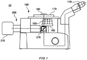
- FIG. 1 is a schematic diagram of a microscope 10.
- the microscope 10 includes an observation optical system 100, an illumination optical system 200, and a light source 210.
- the observation optical system 100 forms an image of a sample 180.
- the observation optical system 100 has an eye piece 110 and an objective lens 160.
- the objective lens 160 is disposed directly under the sample 180 placed on a stage 170, so as to face toward the sample 180.
- a plurality of objective lenses 160 are attached to a revolver 162, where the plurality of objective lenses 160 have respective magnification and objective pupil diameters of the objective lenses, which are different from each other.
- the stage 170 has an observation hole that allows illumination and observation of the sample 180 from the lower side of the diagram, and the sample 180 is placed on the stage 170 to be an object for observation. Also, the stage 170 can be moved separately in the horizontal direction or the vertical direction in an environment where the microscope 10 is put down.
- the illumination optical system 200 irradiates illumination light emitted from the light source 210 to the sample 180.
- a filter cube 270 is disposed directly under the objective lens 160. The filter cube 270 will be described below in detail.
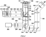
- FIG. 2 is a schematic diagram showing an optical configuration of the microscope 10.
- the observation optical system 100 includes the objective lens 160, the filter cube 270, an imaging lens 150, a plurality of relay lenses 132, 134, and 136 and a plurality of reflection mirrors 120, 142, and 144.
- the objective lens 160 is disposed such that it faces toward an observation surface 191 for a sample 180. Through the objective lens 160 and the imaging lens 150, a primary image 192 of the sample 180 placed on the stage 170 is formed.
- a secondary image 193 is formed via the relay lenses 132, 134, and 136 which relay the primary image 192 formed by the imaging lens 150.
- a user of the microscope 10 observes the secondary image 193 through the eye piece 110.
- the filter cube 270 is disposed between the objective lens 160 and the imaging lens 150.
- the filter cube 270 has an excitation filter 272, a dichroic mirror 274, and a barrier filter 276.
- the excitation filter 272 has a characteristic of, for example, selectively transmitting light in a bandwidth that generates fluorescence to the sample 180 (excitation light), while blocking light in the other bandwidths.
- the dichroic mirror 274 reflects illumination light irradiated from the illumination optical system 200, as well as transmitting observation light such as fluorescence emanated from the sample 180. Thereby, the illumination optical system 200 can perform illumination or excitation of the sample 180 from the same side of the objective lens 160.
- the barrier filter 276 has a characteristic of blocking light in bandwidths, except where the fluorescence is emanated from the sample 180.
- the reflection mirrors 120, 142 and 144 bend an optical path of the observation optical system 100.
- the microscope 10 includes a second observation optical system 202, and a camera 282 that takes an observed image formed by the second observation system 202.
- the second observation optical system 202 shares the objective lens 160, the filter cube 270, and the imaging lens 150 with the observation optical system 100.
- the second observation optical system 202 has relay lenses 284 and a prism 286.
- the prism 286 is replaceably disposed on an optical path of the second observation optical system 202 to reflect observation light and direct it to the relay lenses 284.
- the relay lenses 284 direct the reflected observation light to the camera 282 to form an image.
- the camera 282 uses an image sensor such as a CCD sensor or a CMOS sensor to convert the observed image into an electrical signal to output.
- the illumination optical system 200 has a collector lens 220, a fly-eye lens 230, relay lenses 242 and 244, and a field stop 250.
- the objective lens 160 in the observation optical system 100 also acts as a condenser lens in the illumination optical system 200.
- the illumination optical system 200 shares the filter cube 270 with the observation optical system 100.
- a light emitter such as an LED, an LD or the like is used as the light source 210.
- the collector lens 220 is disposed at a position where its front focus coincide with a light-emitting surface of the light source 210, and makes illumination light emitted from the light source 210 into substantially parallel light.
- the fly-eye lens 230 has a plurality of lens elements 239.
- a pair of relay lenses 242 and 244 is disposed between the fly-eye lens 230 and the objective lens 160.
- the emission end surface of the fly-eye lens 230 is disposed at a pupil conjugate position which is a position conjugate to a pupil position (rear focal position) of the objective lens 160, or vicinity thereto. Note that, the vicinity of the pupil conjugate position is within ⁇ 15 mm from the pupil conjugate position, for example.
- the incident end surface of the fly-eye lens 230 is disposed at a position conjugate to the field stop 250.
- the field stop 250 is disposed between the pair of relay lenses 242 and 244.
- the emission end surface of the fly-eye lens 230 is disposed at a position conjugate to the pupil position (rear focal position) of the objective lens 160 (pupil conjugate position) or vicinity thereto, images of the lens elements 239 are projected on the pupil of the objective lens 160 through the pair of relay lenses 242 and 244, forming a secondary light source.
- images on incident end surfaces of the plurality of lens elements 239 are formed such that they overlap with each other.
- An image conjugate to this image is formed on the observation surface 191 holding the sample 180, and illuminate the sample 180.
- the illumination light source 210, the collector lens 220 and the fly-eye lens 230 may collectively form a replacement unit 209, which can be collectively replaced according to an application of the microscope 10.
- a resin fly-eye lens 230 may be used.
- the LED with a long emission wavelength of 470 nm, the collector lens 220, and the resin fly-eye lens 230 may be combined so that to they can be collectively replaced.
- a quartz or silicone resin fly-eye lens 230 may be used. In this case, the LED with a short emission wavelength of 385 nm, 455 nm etc., the collector lens 220 and the quartz or silicone resin fly-eye lens 230 may be combined so that to they can be collectively replaced.
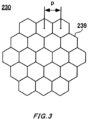
- FIG. 3 is a drawing showing a configuration of the fly-eye lens 230.
- the fly-eye lens 230 has a configuration in which the lens elements 239, each of which is hexagonal, are disposed in a beehive (honeycomb) pattern.
- each lens element 239 has the same curvature radiuses on its incident side and emission side, and when a parallel luminous flux enters from the incident side, it is converged on the emission end surface.
- FIG. 4 are drawings respectively showing images of fly-eye lenses 231, 232, 233, 234 and 235 which are projected on a pupil surface of the objective lens 160.
- the sizes of pupils 251 are the same, whereas respective sizes of images 237 of the lens elements 239 projected on the pupils 251 are different.
- the images 237 of the lens elements are projected on an outer perimeter of the pupils 251.
- the inventers of the present invention have found out that the images 237 of the lens elements projected on the outer perimeter of the pupils 251 affect unevenness in the illumination light.
- ratio of the images 237 of the lens element that pass through the pupil 251 to the images 237 projected on the outer perimeter of the pupil 251, that is, proportion of the images 237 contributing as illumination light differs between the X1 direction and the X2 direction in the drawing two-dimensional unevenness in the illumination light is affected. The same can be said for the direction Y1 and the direction Y2 in the drawing (b) of FIG. 4 .
- the inventers have examined effect of the lens elements 239 projected on the outer perimeter of the pupil 251 upon two-dimensional unevenness in the illumination light. Specifically, they have simulated, from (a) to (e) of FIG. 4 , their respective illuminance distributions on the observation surface 191. In the simulation, the illuminance distributions are calculated in one-dimensional direction.
- the number of the images 237 of the lens elements in the image 231 of the fly-eye lens projected on the pupil 251 is as follows.
- the number (n 2 ) of the images 237 of the lens elements projected on the outer perimeter of the pupil 251 is 6.
- n 2 is the number of the images 237 of the lens elements that cross the outer perimeter of the pupil 251.
- the number (n 1 ) of the images 237 of the lens elements projected inside the pupil 251 is 1.
- n 1 is the number of the images 237 of the lens elements surrounded by the images 237 of the 6 lens elements that cross the outer perimeter of the pupil 251.
- n 2 and n 1 of the image 232 of the fly-eye lens shown in (b) of FIG. 4 are 12 and 7 respectively. Relations between the n 1 and n 2 are shown in Table 1, together with other examples not shown in FIG. 4 .
- [Table 1] NUMBER OF ELEMENTS NUMBER n INNER REGION n 1 PERIPHERAL REGION n 2 INSIDE/OUTSIDE RATIO n 1 /n 2 1 1 6 0.1667 2 7 12 0.5833 3 19 18 1.0566 4 37 24 1.5417 5 61 30 2.0333 6 91 36 2.5278 7 127 42 3.0238 8 169 48 3.5208 9 217 54 4.0185 10 271 60 4.5167
- FIG. 5 is a graph showing respective simulation results of illuminance distributions on the observation surface 191, which correspond to (a) to (e) of FIG. 4 .
- the illuminance distribution in the one-dimensional direction on the observation surface 191 becomes substantially uniform, thus the effect upon unevenness in the illuminance distribution in the two-dimensional direction caused by the images 237 of the lens elements projected on the outer perimeter of the pupil 251 can be reduced. Accordingly, the unevenness in the two-dimensional direction on the observation surface 191 is reduced.
- FIG. 6 is a diagram for explaining correspondence of an image 236 of the lens elements 239 with change of a pupil diameter in the microscope 10.
- the microscope 10 includes the plurality of objective lenses 160 attached to the revolver 162, and can easily switch between the objective lenses 160 to use for observation.
- a pupil diameter may change. For example, when a magnification of the objective lens 160 is changed from ⁇ 10 to ⁇ 40, a pupil diameter may get smaller. That is, upon changing the objective lens 160 to use, a pupil 254 may change to a pupil 256 as shown in FIG. 6 . Therefore, in the microscope 10, the illumination optical system 200 is configured so as to maintain the above condition, i.e., n 1 > n 2 , even when the objective lens 160 is switched and a pupil diameter gets smaller, in order to realize a microscope 10 of which uniformity of illumination light illuminance on the observation surface 191 does not drop by changing the objective lens 160 to be formed.
- the illumination optical system 200 can be configured so as to maintain the relation of n 1 > n 2 , even for the pupil 256 with a small pupil diameter.
- a first objective lens having a first pupil diameter and a second objective lens having a second pupil diameter smaller than the first pupil diameter are switchable, and it is preferable to configure the illumination optical system 200 such that the number n 1 is greater than the number n 2 with respect to the second objective lens.
- the illumination optical system 200 when using more than or equal to 3 switchable objective lenses having pupil diameters different from each other, it is preferable to configure the illumination optical system 200 such that the number n 1 is greater than the number n 2 with respect to an objective lens with the smallest pupil diameter among the plurality of objective lenses.
- FIG. 7 is a schematic diagram showing a configuration of another illumination optical system 201.
- the illumination optical system 201 has the same configuration as that of the illumination optical system 200 shown in FIG. 2 except for the portions described below, thereby the same reference numerals are used for the components in common and redundant descriptions are omitted.
- the illumination optical system 201 is different from the illumination optical system 200, as it has a variable magnification optical system 246 formed of a plurality of lenses instead of having one of the relay lenses 242.
- magnification of the variable magnification optical system 246 is changed, the size of an image of the fly-eye lens 230 to be projected on a pupil surface changes.
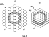
- FIG. 8 is a drawing for explaining an image of the fly-eye lens 230 through the variable magnification optical system 246.
- the variable magnification optical system 246, as shown in (A) of FIG. 8 for example assume that, in an image 290 of the fly-eye lens, the number (n 2 ) of images 237 of lens elements projected on an outer perimeter of a pupil 251 is 12, whereas the number (n 1 ) of images 237 of lens elements projected inside the pupil 251 is 7.
- n 1 and n 2 can be 19 and 18 respectively, by changing magnification of the variable magnification optical system 246 smaller to reduce the size of an image 291 of the fly-eye lens 230 more than the size of the image 290 of the fly-eye lens 230. In this way, by using the variable magnification optical system 246, the n 1 > n 2 condition can be satisfied without changing the fly-eye lens 230 itself.
- FIG. 9 is a diagram showing an image of the light source 210 projected on an emission surface of the fly-eye lens 230 in the illumination optical system 200. Shown in the illustrated example is a case in which an LED with a square light-emitting surface is used as the light source 210. As shown in FIG. 9 , a is a length of each side of the light source 210. Also, a gap between parallel sides opposing to each other of the lens element 239 is equal to an element pitch p.
- Magnification of the light source 210 projected on the emission surface of the fly-eye lens 230 can be expressed by (f FE /f cl ), where f cl and f FE are the focal distance of the collector lens 220 and the focal distance of the lens elements 239 respectively.
- the length of one side of the image of the light source 210 projected on the emission surface of the fly-eye lens 230 is (f FE /f cl )a
- the area in which the LED is projected on each of the emission surfaces of the lens elements 239 can be expressed by (f FE /f cl ) 2 a 2 .
- the area of the emission surfaces of the lens elements 239 is ((3 1/2 ⁇ p 2 )/2).
- a filling rate of the image of the light source 210 in the lens element 239 can be defined as a ratio of the area of the image of the light source 210 to the area of the lens element 239.
- the filling rate it is preferable for the filling rate to be more than or equal to 50%. It is because, if the filling rate is less than 50%, the area of the image of the light source 210 in a pupil 252 is reduced, and thus a substantial NA drops.
- a condition therefor of the illumination optical system 200 is expressed as follows, where a is the length of one side of the light source 210. p ⁇ 2 3 4 a f FE f cl
- the pitch p of the lens element 239 is expressed as follows, where a is the one side length of the light source 210. 3 2 a f FE f cl ⁇ p
- FIG. 10 is a diagram showing an image of a light source 219 projected on the emission surface of the fly-eye lens 230 in the illumination optical system 200. Shown in the illustrated example is a case in which the light source 219 (an optical fiber 219) with diameter b is used instead of the light source 210.
- the diameter and the area of the image of the optical fiber 219 projected on the emission surface of the lens element 239 are expressed by (f FE /f cl )b and ⁇ (f FE /f cl ) 2 (b/2) 2 respectively.
- the filling rate it is preferable for the filling rate to be more than or equal to 50% when the image of the optical fiber 219 is projected inside the emission surface of the lens element 239 in a similar manner as that in FIG.9 described above (an image 218 in FIG. 10 ).
- the image of the optical fiber 219 is larger than the emission surface of the lens element 239 (an image 216 in FIG.
- the pitch p of the lens element 239 is expressed as follows, where b is the diameter of the optical fiber 219. 3 2 b f FE f cl ⁇ p ⁇ ⁇ 3 4 b f FE f cl
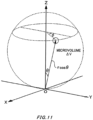
- ⁇ V r cos ⁇ sin ⁇ ⁇ r cos ⁇ d ⁇ ⁇ cos ⁇ dr
- Equation 6 is obtained by integrating this equation, which expresses an acceptance light amount in the range within the emission angle ⁇ from a single point of the light-emitting surface of the light source 210.
- Equation 8 is obtained by solving cos ⁇ 1 on this equation and expressing the result by sin ⁇ 1.
- the illumination optical system 200 with the fly-eye lens 230 can also accommodate another light source 210, such as a halogen lamp.
- another light source 210 such as a halogen lamp.
- an emission end which is a waveguide for an optical fiber or the like that introduces illumination light supplied from the outside can be used as the light source 210.
- the illumination optical system 200 is used for vertical illumination.
- such illumination optical system 200 with the fly-eye lens 230 described above can also be used for illumination of the sample 180 in transmission illumination observation using the microscope 10.
- the above illumination optical system 200 may irradiate illumination light for bright field observation, or may irradiate excitation light for fluorescence observation.
Landscapes
- Physics & Mathematics (AREA)
- General Physics & Mathematics (AREA)
- Optics & Photonics (AREA)
- Chemical & Material Sciences (AREA)
- Analytical Chemistry (AREA)
- Microscoopes, Condenser (AREA)
Claims (6)
- Mikroskop (10), aufweisend:ein optisches Beobachtungssystem (100) mit einer Objektivlinse (160) mit einem vorbestimmten Pupillendurchmesser; undein optisches Beleuchtungssystem (200), das eine Fliegenaugenlinse (230) aufweist und so konfiguriert ist, dass es Licht von einer Lichtquelle (210) durch die Fliegenaugenlinse und die Objektivlinse auf eine Probe (180) strahlt, wobeidie Fliegenaugenlinse eine Vielzahl von Linsenelementen (239) aufweist;in dem optischen Beleuchtungssystem Bilder der Vielzahl von Linsenelementen innerhalb und auf einen äußeren Umfang einer Pupille der Objektivlinse projiziert werden;die Bilder von Linsenelementen, die innerhalb der Pupille der Objektivlinse projiziert werden, Bilder sind, die von den Bildern von Linsenelementen umgeben sind, die auf den äußeren Umfang der Pupille der Objektivlinse projiziert werden; dadurch gekennzeichnet, dasseine Anzahl (n1) von Bildern der Linsenelemente, die innerhalb der Pupille der Objektivlinse projiziert werden, größer ist als eine Anzahl (n2) von Bildern der Linsenelemente, die auf den äußeren Umfang der Pupille der Objektivlinse projiziert werden, wobeieine Vielzahl von Objektivlinsen mit jeweils voneinander unterschiedlichen Pupillendurchmessern umschaltbar sind; unddie Zahl n1 größer ist als die Zahl n2 in Bezug auf eine Objektivlinse mit dem kleinsten Pupillendurchmesser unter der Vielzahl von Objektivlinsen.
- Mikroskop gemäß Anspruch 1, dadurch gekennzeichnet, dass:
ein Satz aus einer Lichtquelle und der Fliegenaugenlinse abnehmbar ist. - Mikroskop gemäß Anspruch 1 oder 2, dadurch gekennzeichnet, dass:in dem optischen Beleuchtungssystem ein Akzeptanzwinkel NA' von Licht, das von einer Lichtquelle ausgestrahlt wird, die folgende Gleichung 1 erfüllt.

- Mikroskop gemäß einem der Ansprüche 1 bis 3, das ferner eine Sammellinse aufweist, um zu bewirken, dass von einer Lichtquelle ausgestrahltes Beleuchtungslicht in die Fliegenaugenlinse eintritt, dadurch gekennzeichnet, dass:wenn eine lichtemittierende Fläche der Lichtquelle eine quadratische Form hat, das optische Beleuchtungssystem die folgende Gleichung 2 erfüllt,
 wobei p ein Pitch der Vielzahl von Linsenelementen ist,a eine Länge einer Seite der lichtemittierenden Fläche ist,fFE eine Brennweite der Linsenelemente ist, undfcl eine Brennweite der Sammellinse ist.
 - Mikroskop gemäß einem der Ansprüche 1 bis 3, das ferner eine Sammellinse aufweist, um zu bewirken, dass von einer Lichtquelle ausgestrahltes Beleuchtungslicht in die Fliegenaugenlinse eintritt, wobei das Mikroskop dadurch gekennzeichnet ist, dass:wenn eine lichtemittierende Fläche der Lichtquelle eine runde Form hat, das optische Beleuchtungssystem die folgende Gleichung 3 erfüllt,
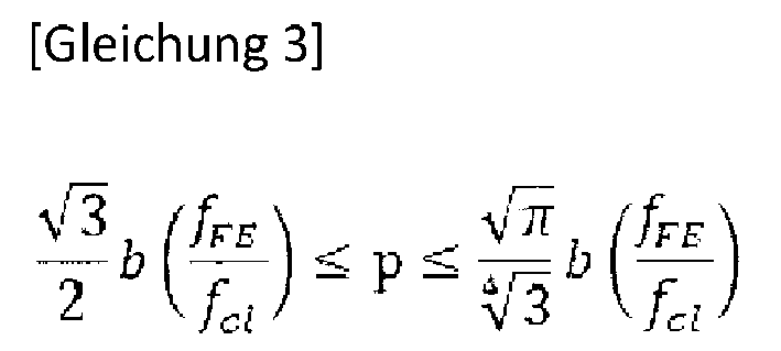 wobei p ein Pitch der Vielzahl von Linsenelementen ist,b ein Durchmesser der lichtemittierenden Fläche ist,fFE eine Brennweite der Linsenelemente ist, undfcl eine Brennweite der Sammellinse ist.
 - Mikroskop gemäß einem der Ansprüche 1 bis 5, wobei das optische Beleuchtungssystem dadurch gekennzeichnet ist, dass es aufweist:
ein optisches System (246) mit variabler Vergrößerung, um die Vergrößerung der Bilder der Vielzahl von Linsenelementen, die auf die Pupille der Objektivlinse projiziert werden, zu ändern.
Applications Claiming Priority (1)
| Application Number | Priority Date | Filing Date | Title |
|---|---|---|---|
| PCT/JP2015/079455 WO2017068627A1 (ja) | 2015-10-19 | 2015-10-19 | 顕微鏡 |
Publications (3)
| Publication Number | Publication Date |
|---|---|
| EP3367152A1 EP3367152A1 (de) | 2018-08-29 |
| EP3367152A4 EP3367152A4 (de) | 2019-06-26 |
| EP3367152B1 true EP3367152B1 (de) | 2024-12-11 |
Family
ID=58557949
Family Applications (1)
| Application Number | Title | Priority Date | Filing Date |
|---|---|---|---|
| EP15906635.6A Active EP3367152B1 (de) | 2015-10-19 | 2015-10-19 | Mikroskop |
Country Status (4)
| Country | Link |
|---|---|
| US (1) | US10802258B2 (de) |
| EP (1) | EP3367152B1 (de) |
| JP (1) | JP6673362B2 (de) |
| WO (1) | WO2017068627A1 (de) |
Families Citing this family (2)
| Publication number | Priority date | Publication date | Assignee | Title |
|---|---|---|---|---|
| JP7730665B2 (ja) * | 2021-05-25 | 2025-08-28 | 株式会社ミツトヨ | 顕微鏡ユニット |
| JP7689866B2 (ja) | 2021-05-25 | 2025-06-09 | 株式会社ミツトヨ | 顕微鏡ユニット |
Family Cites Families (9)
| Publication number | Priority date | Publication date | Assignee | Title |
|---|---|---|---|---|
| JP2004004169A (ja) * | 2002-05-30 | 2004-01-08 | Nikon Corp | 顕微鏡照明装置及び顕微鏡装置 |
| JP5018192B2 (ja) * | 2007-04-06 | 2012-09-05 | 株式会社ニコン | 照明装置 |
| JP2009069691A (ja) | 2007-09-14 | 2009-04-02 | Olympus Corp | 顕微鏡照明装置 |
| JP2009276544A (ja) * | 2008-05-14 | 2009-11-26 | Olympus Corp | 顕微鏡照明装置 |
| JP2009288314A (ja) * | 2008-05-27 | 2009-12-10 | Nikon Corp | 顕微鏡装置 |
| JP2010134191A (ja) * | 2008-12-04 | 2010-06-17 | Nikon Corp | 照明装置と、これを有する顕微鏡装置 |
| JP2010145780A (ja) * | 2008-12-19 | 2010-07-01 | Nikon Corp | インテグレータ、このインテグレータを有する照明装置、及び、この照明装置を有する顕微鏡装置 |
| JP5558162B2 (ja) * | 2010-03-29 | 2014-07-23 | オリンパス株式会社 | 落射蛍光照明装置、及び、それを用いた蛍光顕微鏡 |
| JP5603761B2 (ja) * | 2010-11-29 | 2014-10-08 | オリンパス株式会社 | 蛍光顕微鏡用照明光学系 |
-
2015
- 2015-10-19 JP JP2017546293A patent/JP6673362B2/ja active Active
- 2015-10-19 EP EP15906635.6A patent/EP3367152B1/de active Active
- 2015-10-19 WO PCT/JP2015/079455 patent/WO2017068627A1/ja not_active Ceased
-
2018
- 2018-04-18 US US15/956,516 patent/US10802258B2/en active Active
Also Published As
| Publication number | Publication date |
|---|---|
| US10802258B2 (en) | 2020-10-13 |
| US20180231755A1 (en) | 2018-08-16 |
| JPWO2017068627A1 (ja) | 2018-06-28 |
| JP6673362B2 (ja) | 2020-03-25 |
| EP3367152A1 (de) | 2018-08-29 |
| WO2017068627A1 (ja) | 2017-04-27 |
| EP3367152A4 (de) | 2019-06-26 |
Similar Documents
| Publication | Publication Date | Title |
|---|---|---|
| EP2805670B1 (de) | Verbesserungen an und in zusammenhang mit ophthalmoskopen | |
| WO2015182025A1 (en) | Illumination apparatus, method and medical imaging system | |
| CN105988207B (zh) | 放大光学系统、光学单元和投影仪设备 | |
| US7411735B2 (en) | Illumination system incorporating collimated light source | |
| JP6394071B2 (ja) | 照明装置、照明方法及び内視鏡 | |
| US8926152B2 (en) | Ring light illuminator, beam shaper and method for illumination | |
| KR102047612B1 (ko) | 레이저광 정형 및 파면 제어용 광학계 | |
| US10180234B2 (en) | Illumination optical system, illumination apparatus, and illumination optical element | |
| EP1750154B1 (de) | Mikroskopbeleuchtungsgerät | |
| JP2015223463A (ja) | 照明装置、照明方法及び内視鏡 | |
| KR101907845B1 (ko) | 쾰러조명계를 포함하는 투과 형광현미경 | |
| US10802258B2 (en) | Microscope including an illumination optical system having a plurality of lens elements | |
| JP5533334B2 (ja) | 実体顕微鏡 | |
| CN106461917A (zh) | 光学镜头 | |
| US6980377B1 (en) | Chromatic vignetting in lens systems | |
| JP6642654B2 (ja) | 照明装置、照明方法、内視鏡システム及び医療用観察システム | |
| GB2553559A (en) | Diffusers for head up displays | |
| US7248404B2 (en) | Microscope | |
| CN113126281A (zh) | 宽谱线高分辨率光学系统 | |
| RU127949U1 (ru) | Зеркально-линзовый вариообъектив | |
| EP4151976A1 (de) | Optische vorrichtung, beurteilungsvorrichtung, beurteilungsverfahren und herstellungsverfahren eines optischen systems | |
| JP2020170118A (ja) | 画像検査装置 | |
| JP2011242702A (ja) | 結像光学系及び形状測定装置 | |
| RU20180U1 (ru) | Устройство для формирования оптического пучка | |
| EP4113195A1 (de) | Verfahren und vorrichtung zur strahlformung mit vollbildübertragung für planare lichtquellen |
Legal Events
| Date | Code | Title | Description |
|---|---|---|---|
| STAA | Information on the status of an ep patent application or granted ep patent |
Free format text: STATUS: THE INTERNATIONAL PUBLICATION HAS BEEN MADE |
|
| PUAI | Public reference made under article 153(3) epc to a published international application that has entered the european phase |
Free format text: ORIGINAL CODE: 0009012 |
|
| STAA | Information on the status of an ep patent application or granted ep patent |
Free format text: STATUS: REQUEST FOR EXAMINATION WAS MADE |
|
| 17P | Request for examination filed |
Effective date: 20180418 |
|
| AK | Designated contracting states |
Kind code of ref document: A1 Designated state(s): AL AT BE BG CH CY CZ DE DK EE ES FI FR GB GR HR HU IE IS IT LI LT LU LV MC MK MT NL NO PL PT RO RS SE SI SK SM TR |
|
| AX | Request for extension of the european patent |
Extension state: BA ME |
|
| DAV | Request for validation of the european patent (deleted) | ||
| DAX | Request for extension of the european patent (deleted) | ||
| A4 | Supplementary search report drawn up and despatched |
Effective date: 20190523 |
|
| RIC1 | Information provided on ipc code assigned before grant |
Ipc: G02B 21/06 20060101AFI20190517BHEP Ipc: G02B 3/00 20060101ALI20190517BHEP Ipc: G02B 27/09 20060101ALI20190517BHEP Ipc: G02B 27/30 20060101ALI20190517BHEP |
|
| STAA | Information on the status of an ep patent application or granted ep patent |
Free format text: STATUS: EXAMINATION IS IN PROGRESS |
|
| 17Q | First examination report despatched |
Effective date: 20211223 |
|
| P01 | Opt-out of the competence of the unified patent court (upc) registered |
Effective date: 20230517 |
|
| REG | Reference to a national code |
Ref country code: DE Ref legal event code: R079 Ref document number: 602015090637 Country of ref document: DE Free format text: PREVIOUS MAIN CLASS: G02B0021060000 Ipc: G02B0003000000 |
|
| GRAP | Despatch of communication of intention to grant a patent |
Free format text: ORIGINAL CODE: EPIDOSNIGR1 |
|
| STAA | Information on the status of an ep patent application or granted ep patent |
Free format text: STATUS: GRANT OF PATENT IS INTENDED |
|
| RIC1 | Information provided on ipc code assigned before grant |
Ipc: G02B 21/00 20060101ALN20240617BHEP Ipc: G02B 21/06 20060101ALI20240617BHEP Ipc: G02B 27/09 20060101ALI20240617BHEP Ipc: G02B 21/08 20060101ALI20240617BHEP Ipc: G02B 3/00 20060101AFI20240617BHEP |
|
| INTG | Intention to grant announced |
Effective date: 20240709 |
|
| RAP3 | Party data changed (applicant data changed or rights of an application transferred) |
Owner name: NIKON CORPORATION |
|
| GRAS | Grant fee paid |
Free format text: ORIGINAL CODE: EPIDOSNIGR3 |
|
| GRAA | (expected) grant |
Free format text: ORIGINAL CODE: 0009210 |
|
| STAA | Information on the status of an ep patent application or granted ep patent |
Free format text: STATUS: THE PATENT HAS BEEN GRANTED |
|
| AK | Designated contracting states |
Kind code of ref document: B1 Designated state(s): AL AT BE BG CH CY CZ DE DK EE ES FI FR GB GR HR HU IE IS IT LI LT LU LV MC MK MT NL NO PL PT RO RS SE SI SK SM TR |
|
| REG | Reference to a national code |
Ref country code: GB Ref legal event code: FG4D |
|
| REG | Reference to a national code |
Ref country code: CH Ref legal event code: EP |
|
| REG | Reference to a national code |
Ref country code: IE Ref legal event code: FG4D |
|
| REG | Reference to a national code |
Ref country code: DE Ref legal event code: R096 Ref document number: 602015090637 Country of ref document: DE |
|
| REG | Reference to a national code |
Ref country code: LT Ref legal event code: MG9D |
|
| PG25 | Lapsed in a contracting state [announced via postgrant information from national office to epo] |
Ref country code: HR Free format text: LAPSE BECAUSE OF FAILURE TO SUBMIT A TRANSLATION OF THE DESCRIPTION OR TO PAY THE FEE WITHIN THE PRESCRIBED TIME-LIMIT Effective date: 20241211 |
|
| PG25 | Lapsed in a contracting state [announced via postgrant information from national office to epo] |
Ref country code: FI Free format text: LAPSE BECAUSE OF FAILURE TO SUBMIT A TRANSLATION OF THE DESCRIPTION OR TO PAY THE FEE WITHIN THE PRESCRIBED TIME-LIMIT Effective date: 20241211 |
|
| PG25 | Lapsed in a contracting state [announced via postgrant information from national office to epo] |
Ref country code: BG Free format text: LAPSE BECAUSE OF FAILURE TO SUBMIT A TRANSLATION OF THE DESCRIPTION OR TO PAY THE FEE WITHIN THE PRESCRIBED TIME-LIMIT Effective date: 20241211 |
|
| REG | Reference to a national code |
Ref country code: NL Ref legal event code: MP Effective date: 20241211 |
|
| PG25 | Lapsed in a contracting state [announced via postgrant information from national office to epo] |
Ref country code: ES Free format text: LAPSE BECAUSE OF FAILURE TO SUBMIT A TRANSLATION OF THE DESCRIPTION OR TO PAY THE FEE WITHIN THE PRESCRIBED TIME-LIMIT Effective date: 20241211 |
|
| PG25 | Lapsed in a contracting state [announced via postgrant information from national office to epo] |
Ref country code: NO Free format text: LAPSE BECAUSE OF FAILURE TO SUBMIT A TRANSLATION OF THE DESCRIPTION OR TO PAY THE FEE WITHIN THE PRESCRIBED TIME-LIMIT Effective date: 20250311 |
|
| PG25 | Lapsed in a contracting state [announced via postgrant information from national office to epo] |
Ref country code: LV Free format text: LAPSE BECAUSE OF FAILURE TO SUBMIT A TRANSLATION OF THE DESCRIPTION OR TO PAY THE FEE WITHIN THE PRESCRIBED TIME-LIMIT Effective date: 20241211 Ref country code: GR Free format text: LAPSE BECAUSE OF FAILURE TO SUBMIT A TRANSLATION OF THE DESCRIPTION OR TO PAY THE FEE WITHIN THE PRESCRIBED TIME-LIMIT Effective date: 20250312 |
|
| PG25 | Lapsed in a contracting state [announced via postgrant information from national office to epo] |
Ref country code: RS Free format text: LAPSE BECAUSE OF FAILURE TO SUBMIT A TRANSLATION OF THE DESCRIPTION OR TO PAY THE FEE WITHIN THE PRESCRIBED TIME-LIMIT Effective date: 20250311 |
|
| PG25 | Lapsed in a contracting state [announced via postgrant information from national office to epo] |
Ref country code: NL Free format text: LAPSE BECAUSE OF FAILURE TO SUBMIT A TRANSLATION OF THE DESCRIPTION OR TO PAY THE FEE WITHIN THE PRESCRIBED TIME-LIMIT Effective date: 20241211 |
|
| REG | Reference to a national code |
Ref country code: AT Ref legal event code: MK05 Ref document number: 1750830 Country of ref document: AT Kind code of ref document: T Effective date: 20241211 |
|
| PG25 | Lapsed in a contracting state [announced via postgrant information from national office to epo] |
Ref country code: SM Free format text: LAPSE BECAUSE OF FAILURE TO SUBMIT A TRANSLATION OF THE DESCRIPTION OR TO PAY THE FEE WITHIN THE PRESCRIBED TIME-LIMIT Effective date: 20241211 |
|
| PG25 | Lapsed in a contracting state [announced via postgrant information from national office to epo] |
Ref country code: PL Free format text: LAPSE BECAUSE OF FAILURE TO SUBMIT A TRANSLATION OF THE DESCRIPTION OR TO PAY THE FEE WITHIN THE PRESCRIBED TIME-LIMIT Effective date: 20241211 |
|
| PG25 | Lapsed in a contracting state [announced via postgrant information from national office to epo] |
Ref country code: IS Free format text: LAPSE BECAUSE OF FAILURE TO SUBMIT A TRANSLATION OF THE DESCRIPTION OR TO PAY THE FEE WITHIN THE PRESCRIBED TIME-LIMIT Effective date: 20250411 |
|
| PG25 | Lapsed in a contracting state [announced via postgrant information from national office to epo] |
Ref country code: PT Free format text: LAPSE BECAUSE OF FAILURE TO SUBMIT A TRANSLATION OF THE DESCRIPTION OR TO PAY THE FEE WITHIN THE PRESCRIBED TIME-LIMIT Effective date: 20250411 |
|
| PG25 | Lapsed in a contracting state [announced via postgrant information from national office to epo] |
Ref country code: EE Free format text: LAPSE BECAUSE OF FAILURE TO SUBMIT A TRANSLATION OF THE DESCRIPTION OR TO PAY THE FEE WITHIN THE PRESCRIBED TIME-LIMIT Effective date: 20241211 |
|
| PG25 | Lapsed in a contracting state [announced via postgrant information from national office to epo] |
Ref country code: RO Free format text: LAPSE BECAUSE OF FAILURE TO SUBMIT A TRANSLATION OF THE DESCRIPTION OR TO PAY THE FEE WITHIN THE PRESCRIBED TIME-LIMIT Effective date: 20241211 Ref country code: AT Free format text: LAPSE BECAUSE OF FAILURE TO SUBMIT A TRANSLATION OF THE DESCRIPTION OR TO PAY THE FEE WITHIN THE PRESCRIBED TIME-LIMIT Effective date: 20241211 |
|
| PG25 | Lapsed in a contracting state [announced via postgrant information from national office to epo] |
Ref country code: SK Free format text: LAPSE BECAUSE OF FAILURE TO SUBMIT A TRANSLATION OF THE DESCRIPTION OR TO PAY THE FEE WITHIN THE PRESCRIBED TIME-LIMIT Effective date: 20241211 |
|
| PG25 | Lapsed in a contracting state [announced via postgrant information from national office to epo] |
Ref country code: CZ Free format text: LAPSE BECAUSE OF FAILURE TO SUBMIT A TRANSLATION OF THE DESCRIPTION OR TO PAY THE FEE WITHIN THE PRESCRIBED TIME-LIMIT Effective date: 20241211 |
|
| PG25 | Lapsed in a contracting state [announced via postgrant information from national office to epo] |
Ref country code: IT Free format text: LAPSE BECAUSE OF FAILURE TO SUBMIT A TRANSLATION OF THE DESCRIPTION OR TO PAY THE FEE WITHIN THE PRESCRIBED TIME-LIMIT Effective date: 20241211 |
|
| PG25 | Lapsed in a contracting state [announced via postgrant information from national office to epo] |
Ref country code: SE Free format text: LAPSE BECAUSE OF FAILURE TO SUBMIT A TRANSLATION OF THE DESCRIPTION OR TO PAY THE FEE WITHIN THE PRESCRIBED TIME-LIMIT Effective date: 20241211 |
|
| REG | Reference to a national code |
Ref country code: DE Ref legal event code: R097 Ref document number: 602015090637 Country of ref document: DE |
|
| PG25 | Lapsed in a contracting state [announced via postgrant information from national office to epo] |
Ref country code: DK Free format text: LAPSE BECAUSE OF FAILURE TO SUBMIT A TRANSLATION OF THE DESCRIPTION OR TO PAY THE FEE WITHIN THE PRESCRIBED TIME-LIMIT Effective date: 20241211 |
|
| PLBE | No opposition filed within time limit |
Free format text: ORIGINAL CODE: 0009261 |
|
| STAA | Information on the status of an ep patent application or granted ep patent |
Free format text: STATUS: NO OPPOSITION FILED WITHIN TIME LIMIT |
|
| 26N | No opposition filed |
Effective date: 20250912 |
|
| PGFP | Annual fee paid to national office [announced via postgrant information from national office to epo] |
Ref country code: DE Payment date: 20250902 Year of fee payment: 11 |