EP3366964A1 - Élement ignifuge - Google Patents
Élement ignifuge Download PDFInfo
- Publication number
- EP3366964A1 EP3366964A1 EP17157376.9A EP17157376A EP3366964A1 EP 3366964 A1 EP3366964 A1 EP 3366964A1 EP 17157376 A EP17157376 A EP 17157376A EP 3366964 A1 EP3366964 A1 EP 3366964A1
- Authority
- EP
- European Patent Office
- Prior art keywords
- fire protection
- protection element
- element according
- frame
- intumescent material
- Prior art date
- Legal status (The legal status is an assumption and is not a legal conclusion. Google has not performed a legal analysis and makes no representation as to the accuracy of the status listed.)
- Withdrawn
Links
- 239000003063 flame retardant Substances 0.000 title description 2
- 239000000463 material Substances 0.000 claims abstract description 56
- 239000012528 membrane Substances 0.000 claims abstract description 35
- 238000007789 sealing Methods 0.000 claims abstract description 8
- 239000002184 metal Substances 0.000 claims description 12
- OKTJSMMVPCPJKN-UHFFFAOYSA-N Carbon Chemical compound [C] OKTJSMMVPCPJKN-UHFFFAOYSA-N 0.000 claims description 11
- 239000010439 graphite Substances 0.000 claims description 11
- 229910002804 graphite Inorganic materials 0.000 claims description 11
- 229920002748 Basalt fiber Polymers 0.000 claims description 6
- 229920000049 Carbon (fiber) Polymers 0.000 claims description 6
- 239000004917 carbon fiber Substances 0.000 claims description 6
- 239000000919 ceramic Substances 0.000 claims description 6
- 239000000835 fiber Substances 0.000 claims description 6
- 239000003365 glass fiber Substances 0.000 claims description 6
- 239000000779 smoke Substances 0.000 claims description 6
- 239000011111 cardboard Substances 0.000 claims description 5
- 238000000465 moulding Methods 0.000 description 34
- 241000264877 Hippospongia communis Species 0.000 description 26
- 239000006260 foam Substances 0.000 description 20
- 239000004744 fabric Substances 0.000 description 6
- 239000010410 layer Substances 0.000 description 6
- 239000002245 particle Substances 0.000 description 6
- 238000004519 manufacturing process Methods 0.000 description 5
- 239000007789 gas Substances 0.000 description 3
- 230000003014 reinforcing effect Effects 0.000 description 3
- UGFAIRIUMAVXCW-UHFFFAOYSA-N Carbon monoxide Chemical compound [O+]#[C-] UGFAIRIUMAVXCW-UHFFFAOYSA-N 0.000 description 2
- 239000000654 additive Substances 0.000 description 2
- 238000004132 cross linking Methods 0.000 description 2
- 239000011152 fibreglass Substances 0.000 description 2
- 239000003546 flue gas Substances 0.000 description 2
- 229910052500 inorganic mineral Inorganic materials 0.000 description 2
- 239000011707 mineral Substances 0.000 description 2
- 230000000087 stabilizing effect Effects 0.000 description 2
- 238000003860 storage Methods 0.000 description 2
- 230000003213 activating effect Effects 0.000 description 1
- 238000004026 adhesive bonding Methods 0.000 description 1
- 230000015572 biosynthetic process Effects 0.000 description 1
- 238000004891 communication Methods 0.000 description 1
- 239000000470 constituent Substances 0.000 description 1
- 238000010276 construction Methods 0.000 description 1
- 230000005611 electricity Effects 0.000 description 1
- 230000002349 favourable effect Effects 0.000 description 1
- 239000006261 foam material Substances 0.000 description 1
- 238000009413 insulation Methods 0.000 description 1
- 239000011087 paperboard Substances 0.000 description 1
- 239000011241 protective layer Substances 0.000 description 1
- 230000007704 transition Effects 0.000 description 1
- 238000009423 ventilation Methods 0.000 description 1
Images


Classifications
-
- F—MECHANICAL ENGINEERING; LIGHTING; HEATING; WEAPONS; BLASTING
- F16—ENGINEERING ELEMENTS AND UNITS; GENERAL MEASURES FOR PRODUCING AND MAINTAINING EFFECTIVE FUNCTIONING OF MACHINES OR INSTALLATIONS; THERMAL INSULATION IN GENERAL
- F16L—PIPES; JOINTS OR FITTINGS FOR PIPES; SUPPORTS FOR PIPES, CABLES OR PROTECTIVE TUBING; MEANS FOR THERMAL INSULATION IN GENERAL
- F16L5/00—Devices for use where pipes, cables or protective tubing pass through walls or partitions
- F16L5/02—Sealing
- F16L5/04—Sealing to form a firebreak device
-
- A—HUMAN NECESSITIES
- A62—LIFE-SAVING; FIRE-FIGHTING
- A62C—FIRE-FIGHTING
- A62C2/00—Fire prevention or containment
- A62C2/06—Physical fire-barriers
- A62C2/065—Physical fire-barriers having as the main closure device materials, whose characteristics undergo an irreversible change under high temperatures, e.g. intumescent
-
- B—PERFORMING OPERATIONS; TRANSPORTING
- B32—LAYERED PRODUCTS
- B32B—LAYERED PRODUCTS, i.e. PRODUCTS BUILT-UP OF STRATA OF FLAT OR NON-FLAT, e.g. CELLULAR OR HONEYCOMB, FORM
- B32B3/00—Layered products comprising a layer with external or internal discontinuities or unevennesses, or a layer of non-planar shape; Layered products comprising a layer having particular features of form
- B32B3/10—Layered products comprising a layer with external or internal discontinuities or unevennesses, or a layer of non-planar shape; Layered products comprising a layer having particular features of form characterised by a discontinuous layer, i.e. formed of separate pieces of material
- B32B3/12—Layered products comprising a layer with external or internal discontinuities or unevennesses, or a layer of non-planar shape; Layered products comprising a layer having particular features of form characterised by a discontinuous layer, i.e. formed of separate pieces of material characterised by a layer of regularly- arranged cells, e.g. a honeycomb structure
-
- H—ELECTRICITY
- H02—GENERATION; CONVERSION OR DISTRIBUTION OF ELECTRIC POWER
- H02G—INSTALLATION OF ELECTRIC CABLES OR LINES, OR OF COMBINED OPTICAL AND ELECTRIC CABLES OR LINES
- H02G3/00—Installations of electric cables or lines or protective tubing therefor in or on buildings, equivalent structures or vehicles
- H02G3/02—Details
- H02G3/04—Protective tubing or conduits, e.g. cable ladders or cable troughs
- H02G3/0406—Details thereof
- H02G3/0412—Heat or fire protective means
-
- H—ELECTRICITY
- H02—GENERATION; CONVERSION OR DISTRIBUTION OF ELECTRIC POWER
- H02G—INSTALLATION OF ELECTRIC CABLES OR LINES, OR OF COMBINED OPTICAL AND ELECTRIC CABLES OR LINES
- H02G3/00—Installations of electric cables or lines or protective tubing therefor in or on buildings, equivalent structures or vehicles
- H02G3/22—Installations of cables or lines through walls, floors or ceilings, e.g. into buildings
Definitions
- the invention relates to a fire protection element for sealing off openings passing through walls or ceilings, in particular of line passages, with a molded part of intumescent material.
- Fire protection elements that can close cable ducts with non-refractory pipes or cables in ceilings or walls in case of fire to prevent the spread of fire and smoke in buildings, are known in various designs.
- the fire protection elements typically include an intumescent material with expanded graphite disposed about the leads and a reinforcing insert that stabilizes the intumescent material.
- the expandable graphite particles are activated by the heat at the surface, expand towards the fire and initially form an insulating crust.
- it becomes unstable after some time and falls off.
- the crust is no longer available as an insulating layer, and the underlying intumescent layer is activated.
- the fire protection element burns off step by step and ensures protection only for a limited duration.
- the object of the invention is to provide a fire protection element, which forms a more stable crust in the event of fire and which makes it easier to install cables ordered.
- a fire protection element for sealing off openings passing through walls or ceilings, in particular of line passages, with a molded part made of intumescent material.
- the molded part has a plurality of passage openings for the passage of lines, which extend in particular parallel to each other from a first side to an opposite second side of the fire protection element and are each sealed by a gas-tight sealing membrane.
- the several Through openings in the fire protection element allow a simple way, different types of lines separated from each other by the fire protection element to lead, for example, by electricity and data cables occupy their own through holes. In this way, the fire protection element can be used as a cable management system.
- the membrane ensures that unoccupied through-holes are smoke gas tight.
- the membrane In order to guide a line through a passage opening, the membrane is pierced in the corresponding passage opening. It may be provided a single membrane which closes all passage openings, for example by the membrane extends substantially through the entire molded part. Alternatively, it is also possible to provide a plurality of membranes, each of which closes only a part of the through-openings or only individual through-openings.
- the molding preferably has a honeycomb structure.
- a honeycomb structure is a three-dimensional grid which is constructed in a sectional plane from one or more basic shapes in the form of polygons and extends along an axis which is in particular perpendicular to the sectional plane.
- the honeycomb structure has a uniform, hexagonal basic shape and thus forms a kind of honeycomb or honeycomb.
- the advantage of the fire protection element according to the invention is that due to the lattice-shaped honeycomb structure, the intumescent material can expand into the honeycomb and can there connect with intumescent material of adjacent honeycomb structures. This creates a networked, stable crust in case of fire, which ensures reliable fire protection for a longer period.
- the membrane is located midway between the first and second sides and preferably runs parallel to one of these sides.
- the membrane separates the passage opening into two sections, which have the same depth perpendicular to the first or second side.
- At least part of the passage openings can be filled with a filling foam.
- the filling foam ensures a smoke-tight closure of the passage opening which has been pierced by a line in that the passage opening, in particular completely, is filled with the filling foam. Furthermore, the filling foam is used for storage of the pipes and the sound insulation.
- the fire protection element has a frame which surrounds the molded part in a circumferential direction at least in sections, in particular wherein the circumferential direction extends around an axis which is arranged parallel to the axial extent of the through holes.
- the first and the second side of the molding are not covered by the frame.
- the frame is preferably in one piece. This offers the advantage that there are only a few transition areas between different sections of the frame, in which intumescent material and / or filling material can escape in case of fire. In this way, the frame limits the propagation of the intumescent material in the event of fire and thus makes it possible to direct the expansion of the intumescent material in a desired direction. Thus, since the intumescent material no longer propagates uncontrollably in all directions, the amount of intumescent material in the fire protection element can be reduced, resulting in lower manufacturing costs. Further, different portions of the frame stabilize each other in the expansion of the intumescent material, so that the structural integrity of the fire protection element is improved by this design.
- the frame comprises a material from the following group: cardboard, metal, glass fibers, basalt fibers, carbon fibers, or ceramic fibers. Also, a hybrid structure of the frame of several materials is possible. These materials show in comparison to intumescent material of the molding on a higher temperature resistance. This is advantageous because the frame is not affected by the temperature activating the intumescent material and can thus exert its stabilizing function even in case of fire.
- the frame comprises a metal sheet, an expanded metal, a mineral structural panel, a fiberglass screen or mesh.
- a fabric provides a good connection of the frame with the molding.
- a fabric frame retains its stabilizing properties even with isolated structural damage.
- the frame may comprise an intumescent material, wherein the intumescent material may be identical to the intumescent material of the honeycomb structure.
- the frame expands in case of fire in addition to the intumescent material of the honeycomb structure and ensures a tight closure of the opening and secure storage of the fire protection element in the opening.
- the fire protection element has a cover plate to protect the molded part.
- the cover plate is in particular intended to cover the first or the second side of the fire protection element, which are outside, i. potentially facing the fire. It is advantageous if the cover plate substantially completely covers one side of the molded part. It can also be provided several cover plates, in particular one on the first and one on the second side.
- the cover plate preferably comprises a material from the following group: cardboard, metal, glass fibers, basalt fibers, carbon fibers or ceramic fibers.
- a hybrid construction of the cover plate of several materials is possible. These materials have a high temperature resistance compared to the intumescent material of the molded part and improve the fire protection properties of the fire protection element.
- the cover plate comprises a metal sheet, an expanded metal, a mineral building board, a fiberglass grid or fabric.
- a fabric has the advantage that lines are more easily passed through the cover plate can be. Further, a fabric cover plate maintains its structural integrity even with isolated damage.
- the cover plate may have an intumescent material.
- the cover plate is an additional intumescent layer, which improves the fire protection properties of the fire protection element.
- the molded part has expandable graphite.
- the intumescent material which forms the walls of the through-openings, contains expandable graphite as an essential constituent, in the event of fire branches of expandable graphite particles form in the passage openings, which interlock with other branches of expandable graphite particles from opposite walls and form clusters.
- a networked structure of expanded graphite particles which ensures a particularly high stability of the intumescent crust and thus significantly improves the fire protection properties of the fire protection element.
- the molding is preferably cuboid or cylindrical, in particular circular cylindrical.
- the molding may be a prism.
- the fire protection element has substantially the same shape. This design has the advantage that the fire protection element is particularly suitable for sealing off rectangular or round openings, which occur most frequently in practice. Furthermore, molded parts in these forms are inexpensive to produce and can be stored space efficient.
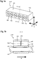
- FIG. 1a an inventive fire protection element 100 is shown with a molding 112 made of intumescent material, which is provided for fireproof closure of component openings with cable bushings such as cables and / or pipes.
- the molding 112 is an approximately parallelepipedic block whose edges extend along the axes X, Y, and Z of an orthogonal coordinate system.
- the molding 112 may have any geometry suitable for securely closing an opening through walls or ceilings.
- the molding 112 may be formed in the shape of a circular cylinder or a prism.
- the molding member 112 has a honeycomb structure 114 formed by through-holes 116 in the form of honeycombs having an equilateral hexagonal basic shape in the X-Y plane and whose honeycomb walls 118 extend axially in the Z direction. This means that the passage openings 116 are arranged parallel to one another.
- the through holes 116 are provided in a tubular shape and each have a membrane 119 (see FIG. 1 b) that completely closes the through hole 116 in the XY plane. Through the membranes 119, the passage openings 116 are closed smoke-tight, so that the fire protection element 100 is by default tight against smoke and gases.
- passage openings 116 are designed identical to one another. Alternatively, passage openings 116 may also be provided, which have different opening cross-sections both in shape and in size.
- passage openings 116 may be provided with a circular cross-sectional area and a diameter which is matched to the diameter of corresponding lines 121.
- lines 121 can be guided through passage openings 116 with a corresponding diameter, so that the honeycomb wall 118 or, in this case, the inner wall of the passage opening 116 rests against the line 121, preferably by means of an interference fit.
- the flue gas tightness of the molding 112 is ensured even after the piercing of the membrane 119, without the need for further action would be required, such as the ejection of the through hole 116 with a sealing foam.
- the arrangement of the through openings 116 is essentially arbitrary. However, it is advantageous if the passage openings 116 are arranged in a symmetrical pattern in order to be able to ensure similar fire protection properties over the entire fire protection element 100.
- the passage openings 116 extend from a first end face 122 to an opposite second end face 123 of the molding part 112. Thus, the passage openings 116 extend in the Z direction through the entire molding part 112.
- the diaphragm 119 is disposed in the axial center of the through-hole 116, i. at the same distance and parallel to the two end faces 122, 123.
- a separate membrane 119 is provided for each passage opening 116.
- the molded part 112 may have a membrane 119 which extends at least in sections through the molded part 112 and closes a plurality or all through openings 116.
- a portion of the through holes 116 may be provided without a membrane.
- the fire protection element 100 would be at least partially permeable to air in the axial direction Z.
- the fire protection element 100 for example, the necessary ventilation in a gap of a wall with a curtain facade but close the gap in case of fire by the reaction of the intumescent material
- the passage openings 116 are provided as passages in the axial direction Z through the molding part 112 for lines.
- the membrane 119 of the corresponding passage opening 116 is pierced.
- the puncturing of the membrane 119 can be done by means of a tool, for example a lance, or without tools, by using one end of the conduit 121 as a lance.
- a passage opening 116 may be provided for one or more conduits 121.
- the intumescent material from which the molded part 112 is formed comprises a proportion of expandable graphite and, depending on requirements, may have a specific intumescent behavior (inter alia foam height and pressure), by means of which the fire protection element 100 can be adapted to different operating conditions.
- the intumescent material has an intumescent volume which ensures a secure closure of the passage openings 116 in the event of a fire.
- the membrane 119 may be formed of the same intumescent material as the molding 112.
- the membrane 119 can be made of any smoke gas-tight material, which preferably has a higher temperature resistance than the intumescent material of the molding 112 and can preferably be pierced without tools with the end of a conduit 121.
- the membrane 119 is elastic so that it can tightly engage around one or more lines 121 passing through it, thereby sealing the passage opening 116.
- the fire protection element 100 provides an ordering system that makes it easier to sort and group different lines. This way you can the fire protection element 100 can be used as a line management system or line order system.
- passage openings 116 may be specially configured for a particular type of conduit.
- a through hole 116 for communication cables could have a sleeve for shielding electromagnetic interference fields.
- FIG. 5 shows a further embodiment of a fire protection element 200 according to the invention comprising a frame 210 and a molded part 212 made of intumescent material with through openings 216 in the form of honeycombs which form a honeycomb structure 214.
- the honeycomb structure 214 extends in comparison to the first embodiment of the fire protection element 100 over the entire molded part 212, which, however, otherwise identical to the molded part 112 of the fire protection element 100 is constructed.
- the molded part 212 has at least one membrane which closes the passage openings 216.
- corresponding reference numerals are therefore assigned below.
- the fire protection element 200 is cuboidal and is enclosed by the frame 210 at its periphery 220 in the circumferential direction U, wherein the end faces 222, 223 of the molding 212 remain free.
- the circumferential direction U extends around the Z-axis, which is arranged parallel to the axial orientation of the passage openings 216.
- the end faces 222, 223 show the basic shape of the honeycomb structure 214 in the X-Y plane and the passage openings 216 extend in the Z direction through the entire molding 212.
- the invention is not limited to fire protection elements 200 with rectangular shaped parts 212 and frame 210, but also includes fire protection elements 200, which have any shape and any cross-section.
- the frame 210 completely covers the periphery 220 except for a narrow slot 224.
- the slot 224 is formed by two oppositely disposed ends 226, 228 of the frame 210, which lie opposite one another on one side of the fire protection element 200.
- the frame 210 may be closed in the circumferential direction U and may not have a slot 224 (see FIG FIG. 4 ).
- the frame 210 is preferably in one piece.
- the frame 210 may be formed of a plurality of interconnected sections.
- the passage openings 216 are filled with a flexible Artschaum 230.
- the passage openings 216 may be filled with a pressure-stable Artschaum 230.
- the filling foam 230 has substantially no fire protection additives.
- the filling foam 230 may comprise fire protection additives to improve the fire protection properties of the fire protection element 200.
- the passage openings 216 are preferably uniformly filled with the filling foam 230 in order to ensure homogeneous properties over the entire molding 212.
- the passage openings 216 may be partially filled with a Guschaum 230.
- the passage openings 216 may be filled with filling foam 230 only at the end faces 222, 223, while the passage openings 216 are empty in the interior. In this way, Guschaum 230 can be saved and the weight of the fire protection element 200 can be reduced.
- different through-openings 216 can be filled with different filling foams 230, or the shaped part 212 can have empty through-openings 216, ie without filling foam 230, in order to combine the properties of the different filling foams 230 or empty through-openings 216.
- different Gremorume 230 for example by a colored marking on the end faces 222, 223, are identifiable. This allows, inter alia, a simplified assembly by lines can be selectively guided through through holes 216 with a Guschaum 230, which offers less resistance in the performance of the lines due to its properties or which rests tightly on the lines and ensures in this way a particularly high density.
- the Golfschaum 230 is fixed, preferably cohesively connected to the honeycomb 214. This ensures that the filling foam 230 is not pressed out of the passage openings 216 when a line is passed through the filling foam 230 or a passage for a line in the filling foam 230 is formed.
- the molding 212 is fixed, preferably cohesively, connected to the frame 210.
- the frame 210 is made of plug metal.
- the frame 210 may be formed of a plate, mat, grid, or web which is preferably made of paperboard, metal, glass fibers, basalt fibers, carbon fibers, or ceramic fibers.
- the frame 210 may comprise an intumescent material, in particular the same intumescent material as the honeycomb 214.
- the frame 210 may be formed solely of intumescent material.
- the frame 210 may additionally comprise the intumescent material, wherein the non-intumescent material of the frame 210 may form a reinforcing insert disposed on a layer of intumescent material or at least partially disposed in a layer of intumescent material. In both cases, the layer of intumescent material is firmly bonded to the reinforcing insert.
- the fire protection element 200 may include a cover plate 232 (see FIG. 3 that covers one side of the fire protection element 200 at least in sections.
- the cover plate 232 covers the end face 222 of the molding 212 and thus forms an additional protective layer.
- the cover plate 232 is made of plug metal.
- the cover plate 232 of a plate, a mat, a Grid or a fabric may be formed, which (s) is preferably made of cardboard, metal, glass fibers, basalt fibers, carbon fibers or ceramic fibers.
- the cover plate 232 may comprise an intumescent material, in particular the same intumescent material as the honeycomb 214.
- the cover plate 232 is fixed, preferably a material fit, connected to the molding 212 and / or the frame 210.
- the cover plate 232 has markings which correspond to the arrangement of the passage openings 216, so that lines can be selectively carried out through the individual passage openings 216 arranged below the cover plate 232.
- the fire protection element 200 may have a plurality of cover plates 232, which are arranged on different sides of the fire protection element 200.
- a plurality of cover plates 232 may be arranged side by side and / or one above the other on one side of the fire protection element 200.
- the production of the molding 112, 212 of the fire protection element 100, 200 according to the invention by means of an intumescent foam, which is introduced into a mold with a corresponding geometry.
- a frame 210 made of intumescent material is provided for the fire protection element 100, 200, then it can be formed directly in this step by means of a corresponding shape.
- the membrane 119 may be provided in the mold so that the through-holes 116, 216 with the membrane 119 can be made in one step.
- the membrane 119 in particular if it is made of a different material than the molding 112, 212, are inserted into the mold, so that the molding 112, 212 is formed in the manufacture corresponding to the membrane 119.
- the membrane 119 between two halves of the molding 112, 212 in particular cohesively, be attached accordingly.
- the passage openings 116, 216 can be ejected with a filling foam 230.
- the frame 210 can be provided in an open form, for example as a plate or with a U-profile.
- the mold part 112, 212 is placed on the frame inside and the ends 226, 228 folded around the mold part 112, 212, whereby the closed frame 210 is formed.
- Slits 224 in frame 210 may be closed by a suitable fire retardant, such as an intumescent liner, and / or injected with an intumescent foam material.
- a suitable fire retardant such as an intumescent liner
- the molding 112, 212 may also be inserted into an already formed frame 210.
- the mold part 112, 212 has a small oversize, so that the mold part 112, 212 is held in the frame 210 by means of a press fit and gaps are securely sealed.
- the molded part 112, 212 can be fastened in the frame 210 in a material-locking manner, for example by gluing, in order to prevent the molded part 112, 212 from being able to be pushed out of the frame 210.
- the frame 210 of the fire protection element 200 is first formed and then the molded part 112, 212 formed directly in the frame 210.
- the frame 210 may serve as part of the mold used to make the molding 112, 212.
- the fire protection element 100, 200 can be made ready to be installed in an opening to be closed.
- the fire protection element 100, 200 can be completed only in the opening to be closed, in particular by the filling foam 230 is first introduced into the through holes 116, 216, when the molding 212 is already disposed in the opening.
- the passage openings 116, 216 can be used to lead lines spaced from each other by the fire protection element 100, 200 before the Greschaum 230 is introduced.
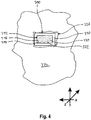
- FIG. 4 a section of a wall 334 is shown with an opening 336, in which a fire protection element 300 is installed as a firewall.
- the fire protection element 300 is arranged so that the end face 322 are aligned substantially parallel to the wall 334 and the sides which are covered by the frame 310, in the direction of the wall 334 point. In this way, the Z-direction through-holes 316 extend through the opening 336, and leads can be passed through the fire protection element 300 without damaging the honeycomb structure 314 and / or the frame 310. Here only the membrane (see FIG. 1 b) are pierced, which seals the passage openings 316.
- a passage in Medschaum 330 can be created, through which the line can be pushed.
- the passage openings 316 of the fire protection element 300 are not filled with a Greet 330 and therefore empty.
- the membrane see FIG. 1b ) the smoke gas tightness of the fire protection element 300 safely.
- FIG. 5 is exemplified by means of a through hole 316, how the fire protection element according to the invention behaves in case of fire.
- a limit temperature is exceeded, the expandable graphite particles in the honeycomb structure 314 are activated and expand as branches 338 into the passage openings 316.
- the branches 338 of different honeycomb walls 318 branch off and form clusters 340, which leads to a cross-linking of the honeycomb structure 314. In this way, the stability of the forming intumescent crust increases, which provides longer-lasting protection.
- the propagation behavior of the branches 338 and the formation of clusters 340 influenced.
- special crosslinking patterns can be provided in this way, which give the fire-protection element 300 particularly favorable fire-protection properties in the event of fire.
- the fire protection element according to the invention can be in this way quickly and easily foreclose a passing through walls or ceilings opening safely and permanently.
- Through the membrane fire protection element according to the invention is smoke-tight even without cable assignment and without further measures.
- a fire protection element is provided with the fire protection element according to the invention, which in addition to the fire protection and the flue gas tightness offers the possibility to separate different types of lines separated and laid in a simple manner.
Landscapes
- Engineering & Computer Science (AREA)
- Architecture (AREA)
- Civil Engineering (AREA)
- Structural Engineering (AREA)
- General Engineering & Computer Science (AREA)
- Mechanical Engineering (AREA)
- Health & Medical Sciences (AREA)
- Public Health (AREA)
- Business, Economics & Management (AREA)
- Emergency Management (AREA)
- Building Environments (AREA)
Priority Applications (5)
| Application Number | Priority Date | Filing Date | Title |
|---|---|---|---|
| EP17157376.9A EP3366964A1 (fr) | 2017-02-22 | 2017-02-22 | Élement ignifuge |
| US16/461,031 US10907751B2 (en) | 2017-02-22 | 2018-02-07 | Fire protection element |
| EP18703324.6A EP3586051A1 (fr) | 2017-02-22 | 2018-02-07 | Élément coupe-feu |
| PCT/EP2018/053012 WO2018153667A1 (fr) | 2017-02-22 | 2018-02-07 | Élément coupe-feu |
| CA3044787A CA3044787A1 (fr) | 2017-02-22 | 2018-02-07 | Element coupe-feu |
Applications Claiming Priority (1)
| Application Number | Priority Date | Filing Date | Title |
|---|---|---|---|
| EP17157376.9A EP3366964A1 (fr) | 2017-02-22 | 2017-02-22 | Élement ignifuge |
Publications (1)
| Publication Number | Publication Date |
|---|---|
| EP3366964A1 true EP3366964A1 (fr) | 2018-08-29 |
Family
ID=58108519
Family Applications (2)
| Application Number | Title | Priority Date | Filing Date |
|---|---|---|---|
| EP17157376.9A Withdrawn EP3366964A1 (fr) | 2017-02-22 | 2017-02-22 | Élement ignifuge |
| EP18703324.6A Withdrawn EP3586051A1 (fr) | 2017-02-22 | 2018-02-07 | Élément coupe-feu |
Family Applications After (1)
| Application Number | Title | Priority Date | Filing Date |
|---|---|---|---|
| EP18703324.6A Withdrawn EP3586051A1 (fr) | 2017-02-22 | 2018-02-07 | Élément coupe-feu |
Country Status (4)
| Country | Link |
|---|---|
| US (1) | US10907751B2 (fr) |
| EP (2) | EP3366964A1 (fr) |
| CA (1) | CA3044787A1 (fr) |
| WO (1) | WO2018153667A1 (fr) |
Families Citing this family (3)
| Publication number | Priority date | Publication date | Assignee | Title |
|---|---|---|---|---|
| PL3559531T3 (pl) * | 2016-12-20 | 2023-05-08 | Rockwool A/S | System do zapewniania ogniobezpiecznego uszczelnienia w otworze w ścianie, suficie lub podłodze budynku, element dla systemu ogniobezpiecznego uszczelnienia i przegroda dla ogniobezpiecznego uszczelnienia w otworze |
| CA3100572A1 (fr) * | 2018-07-17 | 2020-01-23 | Hilti Aktiengesellschaft | Module de passage a monter dans une construction en bois |
| CN111139951B (zh) * | 2020-02-24 | 2021-07-13 | 神华天津煤炭码头有限责任公司 | 可拆装式电缆桥架防火墙及制作方法 |
Citations (6)
| Publication number | Priority date | Publication date | Assignee | Title |
|---|---|---|---|---|
| US3976825A (en) * | 1973-01-15 | 1976-08-24 | Hans Erik Anderberg | Lead-through for electric cables and the like |
| EP0534563A1 (fr) * | 1991-09-27 | 1993-03-31 | Beele Engineering B.V. | Système résistant au feu et procédé pour introduire au moins un câble, tuyau ou similaire à travers une ouverture dans un mur; système résistant au feu et procédé pour empêcher le feu de se propager le long d'une ouverture dans un mur |
| WO2004096369A1 (fr) * | 2003-04-28 | 2004-11-11 | Beele Engineering B.V. | Mousse coupe-feu, elements de construction comprenant cette mousse coupe-feu, systeme permettant de rendre etanche au feu une ouverture et procede permettant d'obturer une ouverture dans une paroi |
| FR2884580A1 (fr) * | 2005-01-21 | 2006-10-20 | Marinoni S P A | Dispositif coupe-feu pour la fermeture provisoire d'ouvertures sur des parois et/ou des ponts |
| WO2011151937A1 (fr) * | 2010-06-04 | 2011-12-08 | 株式会社古河テクノマテリアル | Construction ignifuge pour navires, procédé de réalisation d'une construction ignifuge et procédé d'ajout / retrait / échange de câble à / dans une construction ignifuge temporaire |
| EP2607761A1 (fr) * | 2011-12-22 | 2013-06-26 | HILTI Aktiengesellschaft | Manchette pare-feu |
Family Cites Families (8)
| Publication number | Priority date | Publication date | Assignee | Title |
|---|---|---|---|---|
| US5887396A (en) * | 1998-05-13 | 1999-03-30 | Minnesota Mining And Manufacturing Company | Intumescable fire stop device having quick fasteners |
| JP4142263B2 (ja) * | 2001-02-20 | 2008-09-03 | 株式会社古河テクノマテリアル | 可燃性長尺体貫通部の防火処理用充填材及び防火処理方法 |
| DE102004024501A1 (de) * | 2004-05-18 | 2005-12-15 | Hilti Ag | Brandschutzmaterial |
| CA2502346A1 (fr) * | 2005-03-24 | 2006-09-24 | Royal Group Technologies Limited | Element coupe-feu |
| GB0800765D0 (en) * | 2008-01-16 | 2008-02-27 | Beele Eng Bv | Fire-stop system for placement in a conduit through which a thermally weakenable pipe extends, method for placing the system and conduit provided |
| US8813450B1 (en) * | 2009-03-24 | 2014-08-26 | Emseal Joint Systems Ltd. | Fire and water resistant expansion and seismic joint system |
| DE102011004575A1 (de) * | 2011-02-23 | 2012-08-23 | Hilti Aktiengesellschaft | Leitungselementdurchführung |
| EP2827465A1 (fr) * | 2013-07-17 | 2015-01-21 | HILTI Aktiengesellschaft | Passage de ligne, procédé de fabrication d'un passage de ligne et procédé de montage d'un passage de ligne |
-
2017
- 2017-02-22 EP EP17157376.9A patent/EP3366964A1/fr not_active Withdrawn
-
2018
- 2018-02-07 CA CA3044787A patent/CA3044787A1/fr active Pending
- 2018-02-07 WO PCT/EP2018/053012 patent/WO2018153667A1/fr unknown
- 2018-02-07 US US16/461,031 patent/US10907751B2/en active Active
- 2018-02-07 EP EP18703324.6A patent/EP3586051A1/fr not_active Withdrawn
Patent Citations (6)
| Publication number | Priority date | Publication date | Assignee | Title |
|---|---|---|---|---|
| US3976825A (en) * | 1973-01-15 | 1976-08-24 | Hans Erik Anderberg | Lead-through for electric cables and the like |
| EP0534563A1 (fr) * | 1991-09-27 | 1993-03-31 | Beele Engineering B.V. | Système résistant au feu et procédé pour introduire au moins un câble, tuyau ou similaire à travers une ouverture dans un mur; système résistant au feu et procédé pour empêcher le feu de se propager le long d'une ouverture dans un mur |
| WO2004096369A1 (fr) * | 2003-04-28 | 2004-11-11 | Beele Engineering B.V. | Mousse coupe-feu, elements de construction comprenant cette mousse coupe-feu, systeme permettant de rendre etanche au feu une ouverture et procede permettant d'obturer une ouverture dans une paroi |
| FR2884580A1 (fr) * | 2005-01-21 | 2006-10-20 | Marinoni S P A | Dispositif coupe-feu pour la fermeture provisoire d'ouvertures sur des parois et/ou des ponts |
| WO2011151937A1 (fr) * | 2010-06-04 | 2011-12-08 | 株式会社古河テクノマテリアル | Construction ignifuge pour navires, procédé de réalisation d'une construction ignifuge et procédé d'ajout / retrait / échange de câble à / dans une construction ignifuge temporaire |
| EP2607761A1 (fr) * | 2011-12-22 | 2013-06-26 | HILTI Aktiengesellschaft | Manchette pare-feu |
Also Published As
| Publication number | Publication date |
|---|---|
| CA3044787A1 (fr) | 2018-08-30 |
| WO2018153667A1 (fr) | 2018-08-30 |
| EP3586051A1 (fr) | 2020-01-01 |
| US10907751B2 (en) | 2021-02-02 |
| US20190271416A1 (en) | 2019-09-05 |
Similar Documents
| Publication | Publication Date | Title |
|---|---|---|
| EP3586050B1 (fr) | Élement ignifuge | |
| EP2570157B1 (fr) | Elément ignifuge | |
| DE60103649T2 (de) | Brandschutzabdeckplatte für elektrische steckdosen und schalter | |
| EP2906304B1 (fr) | Manchon coupe-feu | |
| EP3289265B1 (fr) | Manchette coupe-feu | |
| EP3080502B1 (fr) | Dispositif permettant de faire passer des conduites ou des câbles à travers une ouverture de bâtiment | |
| EP2339708B1 (fr) | Guide-câble protégé contre le feu | |
| WO2018153667A1 (fr) | Élément coupe-feu | |
| EP1814634A1 (fr) | Procede pour proteger de la chaleur et/ou du feu un passage de cables et/ou de tuyaux, et element ignifuge utilise a cet effet | |
| EP3586049B1 (fr) | Élement ignifuge | |
| EP3289266B1 (fr) | Manchette coupe-feu | |
| EP3273556A1 (fr) | Collier de passage pour tuyau / passage de câbles ignifugé | |
| EP1429436A2 (fr) | Canalistion de cables protégée contre le feu et sa méthode de fabrication | |
| EP3289267B1 (fr) | Manchette coupe-feu | |
| WO2018219730A1 (fr) | Élément coupe-feu et bandage coupe-feu | |
| EP3246613A1 (fr) | Panneau coupe-feu et caisson modulaire | |
| DE102018110950A1 (de) | Brandschutzmanschette und verfahren zu ihrer herstellung | |
| EP3272965B1 (fr) | Dispositif coupe-feu pour structures de faux-planchers | |
| EP3260173A1 (fr) | Élement ignifuge | |
| EP3366965A1 (fr) | Élément ignifuge et module | |
| DE10303943A1 (de) | Brandgeschützter Kabelkanal und Verfahren zur Herstellung desselben | |
| DE7539331U (de) | Vorrichtung zum sperren des freiraums eines der durchfuehrung mindestens einer versorgungsleitung dienenden kanals |
Legal Events
| Date | Code | Title | Description |
|---|---|---|---|
| PUAI | Public reference made under article 153(3) epc to a published international application that has entered the european phase |
Free format text: ORIGINAL CODE: 0009012 |
|
| AK | Designated contracting states |
Kind code of ref document: A1 Designated state(s): AL AT BE BG CH CY CZ DE DK EE ES FI FR GB GR HR HU IE IS IT LI LT LU LV MC MK MT NL NO PL PT RO RS SE SI SK SM TR |
|
| AX | Request for extension of the european patent |
Extension state: BA ME |
|
| STAA | Information on the status of an ep patent application or granted ep patent |
Free format text: STATUS: THE APPLICATION IS DEEMED TO BE WITHDRAWN |
|
| 18D | Application deemed to be withdrawn |
Effective date: 20190301 |