EP3366931A1 - Sleeve comprising a sensor arrangement with rfid - Google Patents
Sleeve comprising a sensor arrangement with rfid Download PDFInfo
- Publication number
- EP3366931A1 EP3366931A1 EP17157462.7A EP17157462A EP3366931A1 EP 3366931 A1 EP3366931 A1 EP 3366931A1 EP 17157462 A EP17157462 A EP 17157462A EP 3366931 A1 EP3366931 A1 EP 3366931A1
- Authority
- EP
- European Patent Office
- Prior art keywords
- grommet
- spout
- tip
- sleeve
- sensor
- Prior art date
- Legal status (The legal status is an assumption and is not a legal conclusion. Google has not performed a legal analysis and makes no representation as to the accuracy of the status listed.)
- Granted
Links
- 238000009413 insulation Methods 0.000 claims description 10
- 238000004519 manufacturing process Methods 0.000 claims description 4
- 239000002184 metal Substances 0.000 claims description 2
- 239000002023 wood Substances 0.000 claims description 2
- 238000009434 installation Methods 0.000 description 7
- 238000005259 measurement Methods 0.000 description 6
- 238000000034 method Methods 0.000 description 5
- 239000007787 solid Substances 0.000 description 5
- 239000000463 material Substances 0.000 description 4
- 238000013461 design Methods 0.000 description 3
- 239000012528 membrane Substances 0.000 description 3
- 239000004033 plastic Substances 0.000 description 3
- 239000000243 solution Substances 0.000 description 3
- 238000010276 construction Methods 0.000 description 2
- 238000001514 detection method Methods 0.000 description 2
- 230000007613 environmental effect Effects 0.000 description 2
- 230000006870 function Effects 0.000 description 2
- 238000003780 insertion Methods 0.000 description 2
- 230000037431 insertion Effects 0.000 description 2
- 230000035515 penetration Effects 0.000 description 2
- 239000002985 plastic film Substances 0.000 description 2
- 229920006255 plastic film Polymers 0.000 description 2
- 238000012545 processing Methods 0.000 description 2
- XLYOFNOQVPJJNP-UHFFFAOYSA-N water Substances O XLYOFNOQVPJJNP-UHFFFAOYSA-N 0.000 description 2
- 229910000831 Steel Inorganic materials 0.000 description 1
- 239000000853 adhesive Substances 0.000 description 1
- 230000001070 adhesive effect Effects 0.000 description 1
- 239000002313 adhesive film Substances 0.000 description 1
- 230000005540 biological transmission Effects 0.000 description 1
- 238000009529 body temperature measurement Methods 0.000 description 1
- 238000006243 chemical reaction Methods 0.000 description 1
- 230000001143 conditioned effect Effects 0.000 description 1
- 239000004020 conductor Substances 0.000 description 1
- 230000008878 coupling Effects 0.000 description 1
- 238000010168 coupling process Methods 0.000 description 1
- 238000005859 coupling reaction Methods 0.000 description 1
- 238000011161 development Methods 0.000 description 1
- 238000002405 diagnostic procedure Methods 0.000 description 1
- 230000000694 effects Effects 0.000 description 1
- 238000010292 electrical insulation Methods 0.000 description 1
- 238000010291 electrical method Methods 0.000 description 1
- 238000005516 engineering process Methods 0.000 description 1
- 239000006260 foam Substances 0.000 description 1
- 238000003384 imaging method Methods 0.000 description 1
- 230000006698 induction Effects 0.000 description 1
- 238000002347 injection Methods 0.000 description 1
- 239000007924 injection Substances 0.000 description 1
- 238000001746 injection moulding Methods 0.000 description 1
- 239000011810 insulating material Substances 0.000 description 1
- 230000015654 memory Effects 0.000 description 1
- 239000002557 mineral fiber Substances 0.000 description 1
- 239000000203 mixture Substances 0.000 description 1
- 239000002991 molded plastic Substances 0.000 description 1
- 238000007639 printing Methods 0.000 description 1
- 239000000047 product Substances 0.000 description 1
- 230000001681 protective effect Effects 0.000 description 1
- 230000000717 retained effect Effects 0.000 description 1
- 239000004065 semiconductor Substances 0.000 description 1
- 238000000926 separation method Methods 0.000 description 1
- 239000010959 steel Substances 0.000 description 1
- 238000001931 thermography Methods 0.000 description 1
- 239000010409 thin film Substances 0.000 description 1
- 238000010023 transfer printing Methods 0.000 description 1
- 238000003466 welding Methods 0.000 description 1
Images

Classifications
-
- E—FIXED CONSTRUCTIONS
- E04—BUILDING
- E04B—GENERAL BUILDING CONSTRUCTIONS; WALLS, e.g. PARTITIONS; ROOFS; FLOORS; CEILINGS; INSULATION OR OTHER PROTECTION OF BUILDINGS
- E04B1/00—Constructions in general; Structures which are not restricted either to walls, e.g. partitions, or floors or ceilings or roofs
- E04B1/62—Insulation or other protection; Elements or use of specified material therefor
- E04B1/74—Heat, sound or noise insulation, absorption, or reflection; Other building methods affording favourable thermal or acoustical conditions, e.g. accumulating of heat within walls
- E04B1/76—Heat, sound or noise insulation, absorption, or reflection; Other building methods affording favourable thermal or acoustical conditions, e.g. accumulating of heat within walls specifically with respect to heat only
- E04B1/762—Exterior insulation of exterior walls
- E04B1/7629—Details of the mechanical connection of the insulation to the wall
- E04B1/7633—Dowels with enlarged insulation retaining head
-
- G—PHYSICS
- G06—COMPUTING; CALCULATING OR COUNTING
- G06K—GRAPHICAL DATA READING; PRESENTATION OF DATA; RECORD CARRIERS; HANDLING RECORD CARRIERS
- G06K19/00—Record carriers for use with machines and with at least a part designed to carry digital markings
- G06K19/06—Record carriers for use with machines and with at least a part designed to carry digital markings characterised by the kind of the digital marking, e.g. shape, nature, code
- G06K19/067—Record carriers with conductive marks, printed circuits or semiconductor circuit elements, e.g. credit or identity cards also with resonating or responding marks without active components
- G06K19/07—Record carriers with conductive marks, printed circuits or semiconductor circuit elements, e.g. credit or identity cards also with resonating or responding marks without active components with integrated circuit chips
- G06K19/077—Constructional details, e.g. mounting of circuits in the carrier
- G06K19/07749—Constructional details, e.g. mounting of circuits in the carrier the record carrier being capable of non-contact communication, e.g. constructional details of the antenna of a non-contact smart card
- G06K19/07773—Antenna details
-
- G—PHYSICS
- G01—MEASURING; TESTING
- G01D—MEASURING NOT SPECIALLY ADAPTED FOR A SPECIFIC VARIABLE; ARRANGEMENTS FOR MEASURING TWO OR MORE VARIABLES NOT COVERED IN A SINGLE OTHER SUBCLASS; TARIFF METERING APPARATUS; MEASURING OR TESTING NOT OTHERWISE PROVIDED FOR
- G01D11/00—Component parts of measuring arrangements not specially adapted for a specific variable
- G01D11/24—Housings ; Casings for instruments
- G01D11/245—Housings for sensors
-
- F—MECHANICAL ENGINEERING; LIGHTING; HEATING; WEAPONS; BLASTING
- F16—ENGINEERING ELEMENTS AND UNITS; GENERAL MEASURES FOR PRODUCING AND MAINTAINING EFFECTIVE FUNCTIONING OF MACHINES OR INSTALLATIONS; THERMAL INSULATION IN GENERAL
- F16B—DEVICES FOR FASTENING OR SECURING CONSTRUCTIONAL ELEMENTS OR MACHINE PARTS TOGETHER, e.g. NAILS, BOLTS, CIRCLIPS, CLAMPS, CLIPS OR WEDGES; JOINTS OR JOINTING
- F16B13/00—Dowels or other devices fastened in walls or the like by inserting them in holes made therein for that purpose
- F16B13/12—Separate metal or non-separate or non-metal dowel sleeves fastened by inserting the screw, nail or the like
- F16B13/124—Separate metal or non-separate or non-metal dowel sleeves fastened by inserting the screw, nail or the like fastened by inserting a threaded element, e.g. screw or bolt
-
- G—PHYSICS
- G01—MEASURING; TESTING
- G01N—INVESTIGATING OR ANALYSING MATERIALS BY DETERMINING THEIR CHEMICAL OR PHYSICAL PROPERTIES
- G01N33/00—Investigating or analysing materials by specific methods not covered by groups G01N1/00 - G01N31/00
- G01N33/38—Concrete; ceramics; glass; bricks
- G01N33/383—Concrete, cement
Definitions
- the present invention is concerned with a sensor arrangement in building envelopes, in particular for the measurement of environmental parameters and the detection of structural damage.
- leakage detection methods based on different diagnostic methods are used.
- tightness measurements can be carried out with overpressure or by means of imaging thermography, if the leakage creates a thermal bridge.
- Common to all methods is a high expenditure in the application or during installation.
- RFID systems radio-frequency identification
- a transponder with an antenna and a matching reader.
- Such RFID systems have the advantage that not only the identification via the antenna of the transponder, but also the power supply via magnetic alternating fields or by high-frequency radio pulses (induction).
- This power supply is also sufficient to operate simple sensors, such as humidity sensors or temperature sensors. Combined with non-volatile memories, this makes it possible to set up measuring networks that can do without cabling and their own power supply.
- the present invention addresses this problem and proposes, based on the features of main claim 1, an inventive solution.
- the subclaims describe further variants and development stages of the invention.
- the EP 1 175 567 A shows a spout 10, which essentially consists of a head 11 with a large-surface washer 14, at the center hole of which a tubular sleeve 13 adjoins, which conically narrows at the head-distant end to a smaller diameter.
- the sleeve can take a screw (in FIG. 1 not shown), whose shaft can pass through the cone through an axial opening 16, but whose head abuts against the conical constriction 15.
- these spouts can be designed differently, both in terms of the length of the sleeve 13, as well as the size and material of the large-surface washer 14.
- sleeves 13 of different lengths and washers 14 of different diameters and shapes can be combined, which increases the possibilities of use.
- the sleeve 13 is usually designed so that it has a collar at its end facing away from the tip, a circumferential, radially projecting edge, which acts as a stop for a pushed-off from the tip washer 14.
- the invention now proposes to provide a fastener of the type mentioned with an RFID transponder and a sensor. This can - without providing an additional processing step to be introduced in a defined mounting position and depth a sensor in a layer of a roof structure. Likewise, an additional violation of the insulation layers or the roof membrane can be avoided - the already existing attachment point is used. Furthermore, it makes sense to add that in the industry the know-how to install such grommet / screw systems is available, retraining or conversion to the new system can be done very easily. In addition, planning can be simplified. Already now, such fasteners are installed on (for example by wind or alternating load) highly stressed roof areas in higher numbers per square meter. To increase the number of measuring points on such surfaces (for reasons of redundancy or safety) can be realized without great planning effort.
- fasteners can be used according to the prior art, without changing the setting process itself.
- the "intelligent" RFID setting points can be distinguished from the normal attachment points.
- magazine strips in which the fasteners are bundled inserted into a setting device, the number or the ratio of "intelligent" to normal fasteners can be set, thus avoiding a mistake during assembly from the outset.
- a spout 20, 30 consists essentially of a head 21, a tip 22 and a sleeve 23 therebetween, the head 21 being designed as a washer 24 (large area, detachable or fixed, depending on the application) or as a stop collar 17.
- the outer shape of the washer 24 may be (preferably) circular, continue to be executed as an oval, or square with and without Kantenverrundung.
- the tubular sleeve 23 closes, which in turn opens into the tip 22.
- This tip may be preferred have a cone (26) or conical shape 27 and therefore narrows to a smaller diameter than the sleeve 23 has.
- the spout 20, 30 will have a sensor arrangement 25, with at least one RFID transponder with antenna and a sensor operatively connected to the transponder.
- nozzles are, as known in the art, produced as injection molded plastic.
- the sensor assembly can be inserted before the injection molding in the tool and are thus completely or partially enclosed by the plastic of the grommet. Alternatively, a subsequent attachment or attachment of the sensor assembly to the spout is possible.
- the sleeve element with the tip and the washer can be made separately and plugged together before assembly (detachable or, for example, by means of locking or clamping or adhesive elements insoluble) are connected.
- the grommet 20, 30 characterized in that the sensor assembly 25 is mounted flat on the outside of the sleeve 23, on the washer 24 or at the top 22.
- the sensor arrangement may be advantageous to arrange the sensor arrangement on the spout 20, 30 spatially distributed on or on the spout.
- Spatially distributed means a deliberate spatial separation of the sensor (sensor) itself from the transponder with antenna.
- the transponder with antenna is close to the head on the sleeve 23 or on the washer 24 itself, while the sensor is mounted near the top of the sleeve 23 or at the top 22 itself.
- the measuring points are always placed in a defined depth of the insulation layer, while the antenna itself is closer to the surface of the building envelope, which improves the reception and transmission conditions. Since the grommets should occupy all installation positions that are as identical as possible when laying, all sensors are also at the same depth, which enormously facilitates the comparability of resulting measurement results over a roof surface.
- a spout 20, 30 with a detachably mounted sensor assembly 25.
- a detachably mounted sensor assembly 25 lies the advantage in the flexibility of the arrangement of the sensors, if required.
- the sensor assembly 25 is permanently connected to the spout.
- the sensor assembly may be glued, adhered, welded, cast or at least partially integrated into the spout as part of the manufacturing process. Sticking or pinning are useful if the sensor arrangements are present as a separate thin-film component on an adhesive film or intended for welding. It is also conceivable to use the components, the antenna and / or the printed conductors in a printing process, e.g. by a transfer printing process. This would have clear advantages, especially for non-planned documents.
- a grommet 20 on or in the tip 22 will have a passage opening 28 coaxial with the central axis 29 of the sleeve 23.
- This serves for the passage of a fastener 41, which can be inserted head-side with the tip ahead in the spout.
- the attachment to a building envelope then takes place as known from the prior art.
- the nozzle 20, supplemented by the fastener 41 to a fastening element 40, with the insulating layers 42 on a fixed base 43 can be attached.
- the fastener 41 may be part of the fastener 40 is a wood screw, a sheet metal screw, a concrete screw, a bolt or a rivet.
- a spout includes both variants with and without passage opening 28. It would be conceivable and advantageous to use a spout purely as a plug-in element in a roofing membrane or insulation layer, even without them with a fastener 41 as a fastener 44 (see FIG. 4 ) ("plug-in grommet"). The advantages of the depth-accurate attachment are retained, as well as the usual installation together with other fasteners 40.
- a spout 44 may have a tip, as in FIG. 2 shown on the left, which facilitates the penetration of the insulating material 42.
- the sensor arrangement 25 is also considered in connection, comprising an RFID transponder with antenna and at least one sensor operatively connected to the transponder.
- the sensor assembly is designed to be used as part of a fastener 40, which in turn may be used as part of a building shell fastening system 45.
- the head 51 may be disc-shaped as shown, but could in turn also have a specifically shaped engagement for a (manual or motorized) tool or coupling or interface to a turning or striking tool.
- the length A in FIG. 6 determines the setting depth of the sensor carrier 55.
- the upper part 50 thus essentially fulfills the task of a setting tool (applicator) for the sensor carrier 55.
- the sensor carrier 55 itself consists of a rod-shaped body 57, on or in which a sensor arrangement 54 is attached. To the possibilities of attachment (placement and type), the above already applies mutatis mutandis here.
- a tip 53 At one end of the body 57 is a tip 53, at the other end the receptacle 58.
- the sensor carrier 55 is inserted, with the tip 53 ahead, in the insulation layers 42 of the roof structure or driven.
- FIG. 5 shows here the installation situation.
- the body of the sensor carrier 55 can follow the dimensions and materials of the above described for the spout, but this is only preferred, but not mandatory.
- the rod-shaped body 57 can have a round, circular, (polygonal) or square cross-section and can be produced as a hollow body or solid body.
- a mixture is also conceivable, for example with a solid tip and a sleeve-shaped longitudinal body 57.
- the receptacle 58 described above is preferred because it allows a controlled and plannable attachment or insertion of the sensor carrier (control of angle & penetration depth).
- the sensor carrier as in FIG. 5 shown on the right, only to be inserted flush with the surface, it may be possible to dispense with the use of a tool, then the application of the upper part would be omitted and also a special recording 58 would not be necessary.
- a sensor carrier 55 thus comprises a rod-shaped solid and / or hollow body 57 with a round, circular, (poly) square or square Cross-section on or in which a sensor arrangement 54 is attached.
- a sensor arrangement 54 includes, as described above, an RFID transponder and a sensor.
- a tip 53 At one end of the rod-shaped body is a tip 53, at the other end there may be a receptacle which can cooperate positively and / or non-positively with an adapter 56 of an upper part 50.
- the upper part 50 acts as a tool for introducing the sensor carrier and has a head 51, which may have a tool holder and / or a disk-shaped form.
Abstract
Eine Tülle (20, 30) als Teil eines Befestigungselementes für eine Gebäudehülle umfasst im Wesentlichen einen Kopf (21), eine Spitze (22) und eine Hülse (23) dazwischen, wobei der Kopf (21) im Wesentlichen als grossflächige Unterlagscheibe (24) ausgebildet ist, an deren Mittenloch sich die rohrförmige Hülse (23) anschliesst. Die Spitze (22) verjüngt sich sich im Wesentlichen konus- oder kegelförmig auf einen kleineren Durchmesser. Die Tülle (20, 30) weist eine Sensoranordnung (25) auf, mit zumindest einem RFID Transponder mit Antenne und einen mit dem Transponder wirkverbundenen Sensor.A spout (20, 30) as part of a fastener element for a building envelope essentially comprises a head (21), a tip (22) and a sleeve (23) therebetween, the head (21) essentially being a large-area washer (24). is formed, at the center hole, the tubular sleeve (23) adjoins. The tip (22) tapers substantially conical or conical to a smaller diameter. The spout (20, 30) has a sensor arrangement (25), with at least one RFID transponder with antenna and a sensor operatively connected to the transponder.
Description
Die vorliegende Erfindung befasst sich mit einer Sensoranordnung in Gebäudehüllen, insbesondere zur Messung von Umweltparametern und Erkennung von Bauschäden.The present invention is concerned with a sensor arrangement in building envelopes, in particular for the measurement of environmental parameters and the detection of structural damage.
Im Bauwesen sind im zunehmenden Masse hochkomplexe Gebäudehüllen im Einsatz, die aus mehrlagigen, funktionell abgestimmten Schichten bestehen. Dabei werden sowohl bei Aussenwand wie auch Dachkonstruktionen Kombinationen von thermischen Isolationsschichten, tragenden/fixierenden Elementen und Schutzmembranen gegen Umwelteinflüsse wie Wind, Regen, Schnee etc. eingesetzt. Kombinationen von Mineralfaserprodukten, Schaumstoffen, Kunststofffolien und punktförmigen Befestigungselementen dafür sind speziell bei Dachaufbauten heute üblich.
Solche Gebäudehüllen dauerhaft dampf- und wasserdicht zu halten erfordert nicht nur eine abgestimmte Auswahl von Produkten, sondern auch hohe Sorgfalt bei der Verarbeitung und Montage. Bei Industriedächern mit teilweise Tausenden von Quadratmetern, wo Hunderte von Metern an Schweissnähten zwischen Kunststofffolienbahnen anfallen können, sind die Anforderungen besonders hoch. Erschwerend kommt hinzu, dass die zunehmend dicken Isolationslagen je nach Material Wasser aufnehmen können, was dazu führt, dass eventuelle Leckagen erst spät entdeckt werden können und dann der entstandene Schaden bereits hoch ist.In construction, highly complex building envelopes are increasingly being used, consisting of multi-layered, functionally coordinated layers. Combinations of thermal insulation layers, load-bearing / fixing elements and protective membranes against environmental influences such as wind, rain, snow, etc. are used both in the outer wall and roof structures. Combinations of mineral fiber products, foams, plastic films and punctiform fasteners are common today, especially for roof structures.
Keeping such building envelopes permanently steam- and watertight requires not only a coordinated selection of products, but also great care during processing and assembly. In industrial roofs, sometimes thousands of square meters, where hundreds of meters of weld seams between plastic film webs can occur, the requirements are particularly high. To make matters worse, that the increasingly thick insulation layers can absorb water depending on the material, which means that any leaks can be discovered late and then the damage is already high.
Es sind im Stand der Technik verschiedene Lösungen für dieses Problem beschrieben. Zum einen werden Detektionsverfahren für Leckagen eingesetzt, die auf verschiedenen Diagnosemethoden beruhen. Es gibt elektrische Verfahren, bei denen über ein Geflecht von in der Unterkonstruktion angebrachten Leitungen Leckströme messbar werden, sobald sich durch einen lokalen Wassereinbruch die elektrische Isolationswirkung des Dachaufbaus verändert. Alternativ können Dichtheitsmessungen mit Überdruck erfolgen oder aber über bildgebende Thermografie, wenn durch die Leckage eine Wärmebrücke entsteht. Allen Verfahren gemein ist ein hoher Aufwand bei der Anwendung bzw. bei der Installation.Various solutions to this problem have been described in the prior art. On the one hand, leakage detection methods based on different diagnostic methods are used. There are electrical methods in which leakage currents can be measured via a network of cables mounted in the substructure as soon as the electrical insulation effect of the roof structure changes due to a local flooding of the water. Alternatively, tightness measurements can be carried out with overpressure or by means of imaging thermography, if the leakage creates a thermal bridge. Common to all methods is a high expenditure in the application or during installation.
Es wurden auch bereits Verfahren beschrieben, die mit Hilfe von RFID-gekoppelten Sensoren arbeiten. RFID Systeme (radio-frequency identification) verwenden ein als Transponder bezeichnetes Halbleiterbauelement mit einer Antenne und ein dazu passendes Lesegerät. Solche RFID-Systeme haben den Vorteil, dass über die Antenne nicht nur die Identifikation des Transponders erfolgt, sondern auch die Energieversorgung via magnetische Wechselfelder oder durch hochfrequente Radioimpulse (Induktion). Diese Energieversorgung reicht auch aus, um einfache Sensoren zu betreiben, z.B. Feuchtesensoren oder Temperaturfühler. Kombiniert mit nicht-flüchtigen Speichern lassen sich so Messnetze aufbauen, die ohne Verkabelung und eigene Stromversorgung auskommen können.Methods have also been described which operate with the aid of RFID-coupled sensors. RFID systems (radio-frequency identification) use a semiconductor device called a transponder with an antenna and a matching reader. Such RFID systems have the advantage that not only the identification via the antenna of the transponder, but also the power supply via magnetic alternating fields or by high-frequency radio pulses (induction). This power supply is also sufficient to operate simple sensors, such as humidity sensors or temperature sensors. Combined with non-volatile memories, this makes it possible to set up measuring networks that can do without cabling and their own power supply.
Nachteilig bei dieser Lösung ist, dass diese Sensoren mit RFID Transponder separat verlegt werden müssen, z.B. unterhalb oder zwischen verschiedenen Schichten der Gebäudehülle. Auch eine definierte Einbaulage bzw. Einbautiefe (relativ z.B. zur Oberfläche einer Dachfläche) muss gewährleistet sein - einerseits um eine Vergleichbarkeit der Messergebnisse zu erlauben aber auch wegen der Erreichbarkeit des Sensors selbst.The disadvantage of this solution is that these sensors must be routed separately with RFID transponders, e.g. below or between different layers of the building envelope. A defined installation position or mounting depth (for example relative to the surface of a roof surface) must also be ensured - on the one hand to allow comparability of the measurement results but also because of the accessibility of the sensor itself.
Die vorliegende Erfindung befasst sich mit diesem Problem und schlägt, basierend auf den Merkmalen des Hauptanspruchs 1, eine erfinderische Lösung vor. Die Unteransprüche beschreiben weitere Varianten und Ausbaustufen der Erfindung.The present invention addresses this problem and proposes, based on the features of main claim 1, an inventive solution. The subclaims describe further variants and development stages of the invention.
In der Gebäudetechnik sind seit langem Befestigungselemente bekannt, bei denen eine Kombination aus einer Plastiktülle und einem Schraubelement verwendet wird, um eine Dachisolationsbahn auf einem festen Unterbau zu befestigen. Die
Bekanntermassen können diese Tüllen unterschiedlich ausgeführt werden, sowohl was die Länge der Hülse 13 angeht, wie auch Grösse und Material der grossflächigen Unterlagscheibe 14. So ist bekannt, die Hülse 13 und die Unterlagscheibe 14 getrennt zu fertigen. Somit können Hülsen 13 verschiedener Länge und Unterlagscheiben 14 verschiedenen Durchmessers und Form (eckig, rund, oval,...) kombiniert werden, was die Einsatzmöglichkeiten erhöht. Zudem ist es bekannt die Unterlagscheiben 14 z.B. aus geprägtem / gestanztem Stahlblech oder aus Kunststoff zu fertigen. Dann wird in der Regel die Hülse 13 so ausgelegt, dass sie an ihrem der Spitze abgewandtem Ende einen Bund aufweist, einen umlaufenden, radial vorstehenden Rand, der für eine von der Spitze her aufgeschobene Unterlagscheibe 14 als Anschlag wirkt. Dazu können Elemente kommen, die diese Unterlagscheibe lösbar oder dauerhaft fixiert an ihrem Platz halten, wie Rastelemente, Klemmen, Klebungen, etc. Wenn im Folgenden von "Tülle" die Rede ist, ist die grundsätzlichste Ausführungsform gemeint. "Tülle mit grossflächiger Unterlagscheibe" umfasst daher sowohl die ein- wie auch die zweistückige Ausführung.As is known, these spouts can be designed differently, both in terms of the length of the
Die Erfindung schlägt nun vor, ein Befestigungselement der genannten Art mit einem RFID Transponder und einer Sensorik zu versehen. Dadurch kann - ohne einen zusätzlichen Bearbeitungsschritt vorzusehen, in einer definierten Einbaulage und -tiefe ein Sensor in einer Schicht eines Dachaufbaus eingebracht werden. Ebenso kann eine zusätzliche Verletzung der Isolationsschichten bzw. der Dachmembran vermieden werden - es wird der ohnehin vorhandene Befestigungspunkt verwendet. Ferner kommt erleichternd hinzu, dass in der Branche das Knowhow zur Verlegung solcher Tülle/Schraube-Systeme vorhanden ist, eine Umschulung oder Umstellung auf das neue System kann denkbar einfach erfolgen. Zudem kann die Planung vereinfacht werden. Bereits jetzt werden solche Befestigungselemente an (z.B. durch Wind oder Wechselbelastung) hochbeanspruchten Dachbereichen in höherer Anzahl pro Quadratmeter verbaut. Die Anzahl von Messstellen an solchen Flächen zu erhöhen (sei es aus Gründen der Redundanz oder Sicherheit) lässt sich so ohne grossen Planungsaufwand realisieren.The invention now proposes to provide a fastener of the type mentioned with an RFID transponder and a sensor. This can - without providing an additional processing step to be introduced in a defined mounting position and depth a sensor in a layer of a roof structure. Likewise, an additional violation of the insulation layers or the roof membrane can be avoided - the already existing attachment point is used. Furthermore, it makes sense to add that in the industry the know-how to install such grommet / screw systems is available, retraining or conversion to the new system can be done very easily. In addition, planning can be simplified. Already now, such fasteners are installed on (for example by wind or alternating load) highly stressed roof areas in higher numbers per square meter. To increase the number of measuring points on such surfaces (for reasons of redundancy or safety) can be realized without great planning effort.
Dort, wo ein Befestigungspunkt mit Sensorelement nicht notwendig erscheint, können Befestigungselemente (Tülle/Schraube) gemäss Stand der Technik verwendet werden, ohne den Setzvorgang selbst zu verändern. Durch unterschiedliche Farbkennzeichnung können die "intelligenten" RFID-Setzpunkte von den normalen Befestigungspunkten unterschieden werden. Bei Verwendung von Magazinstreifen, in denen die Befestigungselemente gebündelt in ein Setzgerät eingelegt werden, lässt sich die Anzahl bzw. das Verhältnis von "intelligenten" zu normalen Befestigungselementen einstellen und so ein Irrtum bei der Montage von vornherein vermeiden.Where a mounting point with sensor element does not seem necessary, fasteners (spout / screw) can be used according to the prior art, without changing the setting process itself. By different color coding the "intelligent" RFID setting points can be distinguished from the normal attachment points. When using magazine strips, in which the fasteners are bundled inserted into a setting device, the number or the ratio of "intelligent" to normal fasteners can be set, thus avoiding a mistake during assembly from the outset.
Im Kern besteht eine Tülle 20, 30 im Wesentlichen aus einem Kopf 21, einer Spitze 22 und einer Hülse 23 dazwischen, wobei der Kopf 21 eine als (je nach Einsatzfall grossflächige, lösbare oder fixe) Unterlagscheibe 24 ausgebildet sein kann oder als Anschlagbund 17. Die äussere Form der Unterlagscheibe 24 kann (bevorzugt) kreisrund, weiterhin als Oval, oder eckig mit und ohne Kantenverrundung ausgeführt sein. An den Kopf 21 schliesst sich die rohrförmige Hülse 23 an, die wiederum in die Spitze 22 mündet. Diese Spitze kann bevorzugt im Wesentlichen eine Konus- (26) oder Kegelform 27 aufweisen und verengt sich daher auf einen kleineren Durchmesser als die Hülse 23 besitzt. Erfindungsgemäss wird die Tülle 20, 30 eine Sensoranordnung 25 aufweisen, mit zumindest einem RFID Transponder mit Antenne und einen mit dem Transponder wirkverbundenen Sensor.Essentially, a
Diese Tüllen sind, wie die im Stand der Technik Bekannten, als Spritzgiessteil aus Kunststoff herstellbar. Die Sensoranordnung kann dabei vor dem Spritzgiessvorgang in das Werkzeug eingelegt werden und so vom Kunststoff der Tülle ganz oder teilweise umschlossen werden. Alternativ ist auch ein nachträgliches Befestigen bzw. Anbringen der Sensoranordnung an der Tülle möglich. Wie im Stand der Technik können das Hülsenelement mit der Spitze und die Unterlagscheibe separat angefertigt und vor der Montage zusammengesteckt (lösbar oder z.B. durch Rast- oder Klemm- bzw. Klebeelemente unlösbar) verbunden werden.
In einer bevorzugten Ausführungsform zeichnet sich die Tülle 20, 30 dadurch aus, dass die Sensoranordnung 25 flächig auf der Aussenseite der Hülse 23, an der Unterlagscheibe 24 oder an der Spitze 22 angebracht ist. Dadurch ist der Sensor wie auch die Antenne des Transponders nach aussen erkennbar und die Messung erfolgt im direkten Kontakt mit dem umgebenden Material.These nozzles are, as known in the art, produced as injection molded plastic. The sensor assembly can be inserted before the injection molding in the tool and are thus completely or partially enclosed by the plastic of the grommet. Alternatively, a subsequent attachment or attachment of the sensor assembly to the spout is possible. As in the prior art, the sleeve element with the tip and the washer can be made separately and plugged together before assembly (detachable or, for example, by means of locking or clamping or adhesive elements insoluble) are connected.
In a preferred embodiment, the
Je nach Anordnungsprofil kann es von Vorteil sein, die Sensoranordnung auf der Tülle 20, 30 räumlich verteilt auf bzw. an der Tülle anzuordnen. Räumlich verteilt meint hierbei eine bewusste räumliche Trennung des Messfühlers (Sensors) an sich vom Transponder mit Antenne. In einer bevorzugten Variante befindet sich der Transponder mit Antenne kopfnah an der Hülse 23 oder an der Unterlagscheibe 24 selbst, während der Sensor nahe der Spitze an der Hülse 23 oder an der Spitze 22 selbst angebracht ist. Dadurch können z.B. bei Temperaturmessungen die Messpunkte immer in einer definierten Tiefe der Isolationsschicht angebracht werden, während die Antenne selbst näher an der Oberfläche der Gebäudehülle liegt, was die Empfangs- und Sendebedingungen verbessert. Da die Tüllen beim Verlegen alle möglichst identische Einbaulagen einnehmen sollen, liegen auch alle Sensoren in derselben Tiefe, was die Vergleichbarkeit resultierender Messergebnisse über eine Dachfläche enorm erleichtert.Depending on the arrangement profile, it may be advantageous to arrange the sensor arrangement on the
Je nach Auslegung kann es auch vorteilhaft sein, eine Tülle 20, 30mit einer lösbar angebrachten Sensoranordnung 25 vorzusehen. Hier liegt der Vorteil in der Flexibilität der Anordnung der Sensorik, falls gefordert.Depending on the design, it may also be advantageous to provide a
Alternativ und eher bevorzugt ist die Sensoranordnung 25 unlösbar mit der Tülle verbunden. Die Sensoranordnung kann aufgeklebt, angeheftet, angeschweisst, vergossen oder als Teil des Herstellvorgangs zumindest teilweise in die Tülle integriert werden. Aufkleben oder Anheften bieten sich an, wenn die Sensoranordnungen als separates Dünnschichtbauteil auf einer Klebefolie vorliegen oder zum Aufschweissen vorgesehen sind. Denkbar ist ebenfalls, die Bauteile, die Antenne und/oder die Leiterbahnen in einem Druckverfahren, z.B. durch ein Transferdruckverfahren anzubringen. Das hätte vor allem bei nicht-planen Unterlagen deutliche Vorteile.Alternatively, and more preferably, the
In einer erfindungsgemässen Variante wird eine Tülle 20 an bzw. in der Spitze 22 eine zur Zentralachse 29 der Hülse 23 koaxiale Durchtrittsöffnung 28 aufweisen. Diese dient zum Durchtritt eines Befestigers 41, der kopfseitig mit der Spitze voran in die Tülle eingeführt werden kann. Die Befestigung an einer Gebäudehülle erfolgt danach wie aus dem Stand der Technik bekannt. Dabei wird die Tülle 20, ergänzt um den Befestiger 41 zu einem Befestigungselement 40, mit dem Isolationsschichten 42 auf einem festen Unterbau 43 befestigt werden können. Je nach Einsatzprofil bzw. Auslegung kann der Befestiger 41 als Teil des Befestigungselements 40 eine Holzschraube, eine Blechschraube, eine Betonschraube, ein Bolzen oder ein Niet sein.In a variant according to the invention, a
Im Sinne dieser Erfindung umfasst eine Tülle sowohl Varianten mit und ohne Durchtrittsöffnung 28. So wäre denkbar und vorteilhaft, eine Tülle rein als einsteckbares Element in eine Dachbahn bzw. Isolationsschicht einzusetzen, auch ohne sie mit einem Befestiger 41 als Befestigungselement 44 (siehe
Als Teil der Erfindung wird im Zusammenhang auch die Sensoranordnung 25 betrachtet, umfassend einen RFID Transponder mit Antenne und mindestens einen mit dem Transponder wirkverbundenen Sensor. Die Sensoranordnung ist ausgelegt, als Teil eines Befestigungselements 40 eingesetzt zu werden, welches wiederum als Teil eines Befestigungssystems 45 für eine Gebäudehülle verwendbar ist.As part of the invention, the
Auch wenn die Beschreibung nicht alle möglichen Kombinationen der Merkmale direkt ausformuliert, ist damit die Kombinierbarkeit solcher Merkmale nicht ausgeschlossen.Even if the description does not directly formulate all possible combinations of the features, the combinability of such features is not excluded.
-
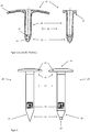
Figur 1 zeigt ein Befestigungselement 10 nach dem Stand der Technik in zwei Varianten. In der Ausführung links ist der Kopf 11 ist als eine grossflächige Unterlagscheibe 14 ausgebildet, die, wie inFigur 4 gezeigt, auf einer Isolationsschicht einer Dachhülle aufliegen kann und dann die vertikalen Zugkräfte verteilt. Die Variante inFigur 1 rechts besitzt nur einen Anschlagbund 17, der mit verschiedenen Unterlagscheiben kombiniert werden kann. Eine rohrförmige Hülse 13 verbindet jeweils den Kopf 11 mit einer konischen Spitze 12, wie im Schnitt gezeigt. Die Hülse verengt sich am im Konus bei Merkmal 15 und geht über in eine axiale Öffnung 16.FIG. 1 shows a fastener 10 according to the prior art in two variants. In the embodiment on the left, thehead 11 is designed as a large-surface washer 14, which, as inFIG. 4 shown, can rest on an insulating layer of a roof shell and then distributed the vertical tensile forces. The variant inFIG. 1 right has only onestop collar 17, which can be combined with different washers. Atubular sleeve 13 respectively connects thehead 11 to aconical tip 12, as shown in section. The sleeve narrows at the cone infeature 15 and merges into anaxial opening 16. -
Figur 2 zeigt die zwei bevorzugten Hauptvarianten der erfindungsgemässen Tülle. Die Variante in derFigur 2 rechts entspricht einer Tülle 20, deren Verwendungszweck die Funktion als Teil eines Befestigungselementes einschliesst, wie inFigur 4 illustriert ("Befestigungstülle"). Die Variante einer Tülle 30, im Bild links, entspricht dem reinen Einsteckelement ohne Befestigungsfunktion ("Einstecktülle"). Der Aufbau aus Kopf 21 mit Unterlagscheibe 24, Hülse 23 und Spitze 22 entspricht im Wesentlichen dem vonFigur 1 und ist für Tülle 20 wie 30 vergleichbar. Die Form der Spitze 22 ist technisch bedingt und wird vom Fachmann unter Berücksichtigung fertigungstechnischer Vorgaben so ausgelegt werden, wie es der Einsatzzweck erfordert. Für die Einstecktülle 30 mit Spitze 27 empfiehlt sich eine geschlossene Spitze. Die Befestigungstülle 20 weist an der Spitze die Durchtrittsöffnung 28 auf, um einen Befestiger 41 aufzunehmen wie inFigur 3 bzw.Figur 4 gezeigt. Diese Öffnung ist koaxial mit der Zentralachse 29 der Hülse 23. Die Anbringung der Sensoranordnung 25 ist exemplarisch gezeigt, illustriert aber, dass sowohl die Befestigungstülle wie auch die Einstecktülle dieselbe Einbaulage und -tiefe erlauben.FIG. 2 shows the two preferred main variants of the inventive spout. The variant in theFIG. 2 right corresponds to aspout 20, the use of which includes the function as part of a fastener, as inFIG. 4 illustrated ("Fastening grommet"). The variant of aspout 30, in the picture on the left, corresponds to the pure plug-in element without fastening function ("plug-in spout"). The construction ofhead 21 withwasher 24,sleeve 23 andtip 22 substantially corresponds to that ofFIG. 1 and is comparable forspout 20 like 30. The shape of thetip 22 is technically conditioned and will be interpreted by the skilled worker taking into account manufacturing specifications as it requires the application. For theEinstecktülle 30 withtip 27, a closed tip is recommended. Thegrommet 20 has at the top of thepassage opening 28 to receive afastener 41 as inFIG. 3 or.FIG. 4 shown. This opening is coaxial with thecentral axis 29 of thesleeve 23. The attachment of thesensor assembly 25 is shown as an example, but illustrates that allow both the grommet and the Einsteckge the same installation position and depth. -
Figur 3 zeigt die Kombination einer Befestigungstülle 20 mit einem eingesteckten Befestiger 41 als Befestigungselement 40.FIG. 3 shows the combination of agrommet 20 with an insertedfastener 41 as a fastener 40th -
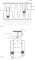
Figur 4 zeigt ein Befestigungssystem 45 mit einem festen Unterbau 43, einer darauf angeordneten Isolationsschicht 42 und einer Deckfolie 46. Der Befestiger 41 eines Befestigungselements 40 ist in dem Unterbau 43 verankert, während die Einstecktülle 48 ohne Befestiger auskommt. Die Einbautiefe der Sensoranordnung ist dieselbe. Dies ist kein zwingendes merkmal, durch die unterschiedliche Anordnung gleicher Sensortypen liessen sich ohne weiteres Querschnittsmessungen eines gewählten Parameters (Temperatur, Feuchte,...) über die Schicht 42 erreichen.FIG. 4 shows afastening system 45 with a fixedbase 43, an insulatinglayer 42 disposed thereon and acover sheet 46. Thefastener 41 of afastener 40 is anchored in thebase 43, while the Einstecktülle 48 does not require fasteners. The installation depth of the sensor arrangement is the same. This is not a mandatory feature, because of the different arrangement of the same sensor types, cross-sectional measurements of a selected parameter (temperature, humidity,...) Over thelayer 42 could easily be achieved. -
Figur 6 zeigt zwei Varianten der weiter oben beschriebenen bzw. inFigur 2 gezeigten "Einstecktülle" 30 mit unterschiedlichen Spitzenformen und -längen. Eine Besonderheit ist hierbei die Ausführung in zwei Teilen. Ein Oberteil 50 besteht vorrangig aus einem Kopf 51 und einem stabförmigen Körper 52. Dieser weist optional an seinem vom Kopf 51 abgewandten Ende einen Adapter 56 auf, welcher mit einem Gegenstück an einem Sensorträger 55 korrespondieren kann. Der Adapter kann ein Konus sein, ein Zylinder, ein Vierkant oder ein Vielkant. Das Gegenstück, eine Aufnahme 58, wird entsprechend so geformt, dass es kraftoder formschlüssig verbunden werden kann. Die Platzierung von Adapter 56 und Aufnahme 58 kann natürlich auch umgekehrt werden.FIG. 6 shows two variants of those described above or inFIG. 2 shown "Einstecktülle" 30 with different tip shapes and lengths. A special feature here is the execution in two parts. Anupper part 50 consists primarily of ahead 51 and a rod-shapedbody 52. This optionally has at its end remote from thehead 51 anadapter 56, which may correspond to a counterpart on asensor carrier 55. The adapter can be a cone, a cylinder, a square or a polygon. The counterpart, areceptacle 58, is correspondingly shaped so that it can be positively or positively connected. The placement ofadapter 56 andreceptacle 58 can of course be reversed.
Der Kopf 51 kann, wie gezeigt, scheibenförmig ausgeführt sein, könnte aber wiederum auch einen spezifisch geformten Angriff für ein (manuelles oder motorisiertes) Werkzeug bzw. eine Kupplung oder eine Schnittstelle zu einem Dreh- oder Schlagwerkzeug. Die Länge A in Figur 6 bestimmt in der gezeigten Ausführung die Setztiefe des Sensorträgers 55. Das Oberteil 50 insgesamt erfüllt somit im Wesentlichen die Aufgabe eines Setzwerkzeugs (Applikator) für den Sensorträger 55.The
Der Sensorträger 55 selbst besteht aus einem stabförmigen Körper 57, auf bzw. in dem eine Sensoranordnung 54 angebracht ist. Zu den Möglichkeiten der Anbringung (Platzierung und Art) gilt das bereits oben Geschilderte sinngemäss auch hier. An einem Ende des Körpers 57 befindet sich eine Spitze 53, am anderen Ende die Aufnahme 58. Der Sensorträger 55 wird, mit der Spitze 53 voran, in die Isolationsschichten 42 des Dachaufbaus eingesteckt bzw. eingetrieben.
In der einfachsten Ausführung umfasst somit ein Sensorträger 55 damit einen stabförmigen Voll- und/oder Hohl-Körper 57 mit einem runden, kreisrunden, (viel-)eckigen bzw. quadratischen Querschnitt, auf bzw. in dem eine Sensoranordnung 54 angebracht ist. Diese umfasst, wie oben beschrieben, einen RFID Transponder und einen Sensor. An einem Ende des stabförmigen Körpers befindet sich eine Spitze 53, am anderen Ende kann sich eine Aufnahme befinden, die form- und/oder kraftschlüssig mit einem Adapter 56 eines Oberteils 50 zusammenwirken kann. Das Oberteil 50 wirkt als Werkzeug zur Einbringung des Sensorträgers und hat einen Kopf 51, der eine Werkzeugaufnahme und/oder eine scheibenförmige Form aufweisen kann.In the simplest embodiment, a
- 1010
- Tüllespout
- 2020
- Tülle, BefestigungstülleGrommet, grommet
- 30, 4830, 48
- Tülle, EinstecktülleGrommet, insertion grommet
- 1111
- Kopfhead
- 1212
- Spitzetop
- 1313
- (rohrförmige) Hülse(tubular) sleeve
- 1414
- (grossflächige) Unterlagscheibe(large area) washer
- 1515
- Konus-VerengungCone narrowing
- 1616
- axiale Öffnungaxial opening
- 1717
- Bund, AnschlagbundBund, stop collar
- 2121
- Kopfhead
- 2222
- Spitzetop
- 2323
- (rohrförmige) Hülse(tubular) sleeve
- 2424
- Unterlagscheibewasher
- 2525
- Sensoranordnungsensor arrangement
- 2626
- konusförmige Spitzecone-shaped tip
- 2727
- kegelförmige Spitzeconical tip
- 2828
- DurchtrittsöffnungThrough opening
- 2929
- Zentralachsecentral axis
- 4040
- Befestigungselementfastener
- 4141
- Befestigerfasteners
- 4242
- Isolationsschicht(en)Insulation layer (s)
- 4343
- (fester) Unterbau(solid) substructure
- 4444
- Tülle (ohne Durchtrittsöffnung 28)Grommet (without opening 28)
- 4545
- Befestigungssystem für GebäudehülleFixing system for building envelope
- 4646
- Deckfoliecover sheet
- 5050
- Oberteiltop
- 5151
-
Kopf 51
Head 51 - 5252
- (stabförmiger) Körper(rod-shaped) body
- 5353
- Spitzetop
- 5454
- Sensoranordnungsensor arrangement
- 5555
- Sensorträgersensor support
- 5656
- Adapteradapter
- 5757
- (Stabförmiger) Körper(Rod-shaped) body
- 5858
- Aufnahmeadmission
Claims (9)
Priority Applications (6)
| Application Number | Priority Date | Filing Date | Title |
|---|---|---|---|
| ES17157462T ES2877196T3 (en) | 2017-02-22 | 2017-02-22 | Cuff comprising a sensing device with RFID |
| PL17157462T PL3366931T3 (en) | 2017-02-22 | 2017-02-22 | Sleeve comprising a sensor arrangement with rfid |
| EP17157462.7A EP3366931B1 (en) | 2017-02-22 | 2017-02-22 | Sleeve comprising a sensor arrangement with rfid |
| DK17157462.7T DK3366931T3 (en) | 2017-02-22 | 2017-02-22 | Tulle comprising a sensor arrangement with RFID |
| US15/901,224 US10713554B2 (en) | 2017-02-22 | 2018-02-21 | Sensor arrangement with RFID |
| CN201810153222.5A CN108458737B (en) | 2017-02-22 | 2018-02-22 | Sleeve pipe |
Applications Claiming Priority (1)
| Application Number | Priority Date | Filing Date | Title |
|---|---|---|---|
| EP17157462.7A EP3366931B1 (en) | 2017-02-22 | 2017-02-22 | Sleeve comprising a sensor arrangement with rfid |
Publications (2)
| Publication Number | Publication Date |
|---|---|
| EP3366931A1 true EP3366931A1 (en) | 2018-08-29 |
| EP3366931B1 EP3366931B1 (en) | 2021-06-16 |
Family
ID=58162461
Family Applications (1)
| Application Number | Title | Priority Date | Filing Date |
|---|---|---|---|
| EP17157462.7A Active EP3366931B1 (en) | 2017-02-22 | 2017-02-22 | Sleeve comprising a sensor arrangement with rfid |
Country Status (6)
| Country | Link |
|---|---|
| US (1) | US10713554B2 (en) |
| EP (1) | EP3366931B1 (en) |
| CN (1) | CN108458737B (en) |
| DK (1) | DK3366931T3 (en) |
| ES (1) | ES2877196T3 (en) |
| PL (1) | PL3366931T3 (en) |
Cited By (1)
| Publication number | Priority date | Publication date | Assignee | Title |
|---|---|---|---|---|
| EP4180791A1 (en) | 2021-11-10 | 2023-05-17 | SFS Group International AG | Sensor arrangement |
Families Citing this family (2)
| Publication number | Priority date | Publication date | Assignee | Title |
|---|---|---|---|---|
| KR20200108448A (en) | 2018-01-11 | 2020-09-18 | 조프리 그로브 | Metal fastener with embedded RFID tag and manufacturing method |
| WO2021072089A1 (en) * | 2019-10-08 | 2021-04-15 | California Institute Of Technology | Airflow sensing based adaptive nonlinear flight control of a flying car or fixed-wing vtol |
Citations (3)
| Publication number | Priority date | Publication date | Assignee | Title |
|---|---|---|---|---|
| EP1175567A1 (en) | 1999-05-06 | 2002-01-30 | SFS intec Holding AG | Fixing element for fixing insulating strips or plates on a solid substructure |
| KR20070092374A (en) * | 2006-03-09 | 2007-09-13 | 조현아 | Underground-construction indication nail having a rfid and search system for underground-construction information thereof |
| JP2015215226A (en) * | 2014-05-09 | 2015-12-03 | オムロン株式会社 | State detection device |
Family Cites Families (11)
| Publication number | Priority date | Publication date | Assignee | Title |
|---|---|---|---|---|
| US7278341B1 (en) * | 2005-06-24 | 2007-10-09 | Selective Site Consultants, Inc. | Structural bolt security apparatus |
| CA2614213A1 (en) * | 2005-08-19 | 2007-02-22 | Telezygology Inc. | Strip fastener |
| US8683869B2 (en) * | 2008-09-04 | 2014-04-01 | The Boeing Company | Monitoring fastener preload |
| CN101737389B (en) * | 2009-12-31 | 2015-09-30 | 马宇尘 | A kind of nail realizing radio-frequency tag function |
| DE102012201293A1 (en) * | 2012-01-31 | 2013-08-01 | Hilti Aktiengesellschaft | Anchor system, in particular undercut anchor system |
| CN203551140U (en) * | 2013-10-19 | 2014-04-16 | 国家电网公司 | Passive wireless temperature sensor |
| CN105960582B (en) * | 2014-04-04 | 2019-04-26 | 应变实验室有限公司 | Intelligent bolt and its system |
| US9493133B2 (en) * | 2014-05-20 | 2016-11-15 | Ford Global Technologies, Llc | Fastening and sensing apparatus |
| US20160126664A1 (en) * | 2014-10-31 | 2016-05-05 | Motorola Solutions, Inc | Connector providing combined fastener and radio frequency interface |
| CN205533657U (en) * | 2016-01-29 | 2016-08-31 | 武汉中科鑫海科技有限公司 | Implant RFID electronic tags's bolt |
| CN106137359A (en) * | 2016-07-22 | 2016-11-23 | 张立沼 | A kind of orthopaedics lock screw |
-
2017
- 2017-02-22 PL PL17157462T patent/PL3366931T3/en unknown
- 2017-02-22 ES ES17157462T patent/ES2877196T3/en active Active
- 2017-02-22 DK DK17157462.7T patent/DK3366931T3/en active
- 2017-02-22 EP EP17157462.7A patent/EP3366931B1/en active Active
-
2018
- 2018-02-21 US US15/901,224 patent/US10713554B2/en active Active
- 2018-02-22 CN CN201810153222.5A patent/CN108458737B/en active Active
Patent Citations (3)
| Publication number | Priority date | Publication date | Assignee | Title |
|---|---|---|---|---|
| EP1175567A1 (en) | 1999-05-06 | 2002-01-30 | SFS intec Holding AG | Fixing element for fixing insulating strips or plates on a solid substructure |
| KR20070092374A (en) * | 2006-03-09 | 2007-09-13 | 조현아 | Underground-construction indication nail having a rfid and search system for underground-construction information thereof |
| JP2015215226A (en) * | 2014-05-09 | 2015-12-03 | オムロン株式会社 | State detection device |
Cited By (1)
| Publication number | Priority date | Publication date | Assignee | Title |
|---|---|---|---|---|
| EP4180791A1 (en) | 2021-11-10 | 2023-05-17 | SFS Group International AG | Sensor arrangement |
Also Published As
| Publication number | Publication date |
|---|---|
| DK3366931T3 (en) | 2021-09-20 |
| CN108458737B (en) | 2022-06-24 |
| EP3366931B1 (en) | 2021-06-16 |
| ES2877196T3 (en) | 2021-11-16 |
| US10713554B2 (en) | 2020-07-14 |
| CN108458737A (en) | 2018-08-28 |
| US20180240004A1 (en) | 2018-08-23 |
| PL3366931T3 (en) | 2021-11-02 |
Similar Documents
| Publication | Publication Date | Title |
|---|---|---|
| EP3366931B1 (en) | Sleeve comprising a sensor arrangement with rfid | |
| EP1868885B1 (en) | Aircraft structural element provided with a cavity and drainage element | |
| DE102007016236B3 (en) | Spacer for fixing a retaining element in a wall | |
| EP0086452A2 (en) | Method of fixing an insulating slab to be plastered to a building surface | |
| DE2455918A1 (en) | PIPE COUPLING | |
| EP0397168B1 (en) | Cryostat | |
| DE2433669C2 (en) | Device for fastening a loosely laid roof waterproofing membrane | |
| DE202012008452U1 (en) | immersion probe | |
| DE102014220249A1 (en) | Rotor blade of a wind turbine | |
| EP2122084A1 (en) | Fastening device | |
| WO2014139946A1 (en) | Nozzle and fastening element for fastening a material layer | |
| DE1947332U (en) | FASTENING ELEMENT MADE OF TOAELASTIC MATERIAL. | |
| EP3126575B1 (en) | Bridge cap and fastening unit for fastening a bridge cap | |
| DE102004050675A1 (en) | Cable lug attaching device, has collar for arrangement of cable lug, and capnut with threaded hole and clamping plane is screwed on threaded shaft, where cable lug is tightened between support flange and clamping plane | |
| AT413993B (en) | INSULATED FASTENING DEVICE FOR INSULATED FAÇADES | |
| DE102008034409B4 (en) | Foil penetration element and its use | |
| DE102011089942A1 (en) | Receiving device for measuring insert, has mold portion for fastening receiving device to pipeline, where mold portion has bore, in which component is inserted from end of bore | |
| DE102016009614A1 (en) | fastening device | |
| EP3101188A1 (en) | Insulation mount for fastening insulation panels to a substrate | |
| EP0166982A1 (en) | Connecting device to construct a multidimensional construction | |
| DE10315099A1 (en) | Device for watering roads | |
| EP3775434A1 (en) | Boom arm with inner pipe holder screw connection | |
| EP2712972A2 (en) | Spacer for fixing an object to a wall which is insulated | |
| EP3842774B1 (en) | Holding device for a temperature sensor, immersion tube with such a holding device and device with such an immersion tube | |
| DE202006017450U1 (en) | Connecting adapter e.g. for coaxial connection of two mast sections of mast building group, has base having two connecting surfaces enclosing and providing actuated connection between base and end |
Legal Events
| Date | Code | Title | Description |
|---|---|---|---|
| PUAI | Public reference made under article 153(3) epc to a published international application that has entered the european phase |
Free format text: ORIGINAL CODE: 0009012 |
|
| STAA | Information on the status of an ep patent application or granted ep patent |
Free format text: STATUS: REQUEST FOR EXAMINATION WAS MADE |
|
| 17P | Request for examination filed |
Effective date: 20180130 |
|
| AK | Designated contracting states |
Kind code of ref document: A1 Designated state(s): AL AT BE BG CH CY CZ DE DK EE ES FI FR GB GR HR HU IE IS IT LI LT LU LV MC MK MT NL NO PL PT RO RS SE SI SK SM TR |
|
| AX | Request for extension of the european patent |
Extension state: BA ME |
|
| RAP1 | Party data changed (applicant data changed or rights of an application transferred) |
Owner name: SFS INTEC HOLDING AG |
|
| STAA | Information on the status of an ep patent application or granted ep patent |
Free format text: STATUS: EXAMINATION IS IN PROGRESS |
|
| 17Q | First examination report despatched |
Effective date: 20191004 |
|
| STAA | Information on the status of an ep patent application or granted ep patent |
Free format text: STATUS: EXAMINATION IS IN PROGRESS |
|
| GRAP | Despatch of communication of intention to grant a patent |
Free format text: ORIGINAL CODE: EPIDOSNIGR1 |
|
| STAA | Information on the status of an ep patent application or granted ep patent |
Free format text: STATUS: GRANT OF PATENT IS INTENDED |
|
| INTG | Intention to grant announced |
Effective date: 20210310 |
|
| GRAS | Grant fee paid |
Free format text: ORIGINAL CODE: EPIDOSNIGR3 |
|
| GRAA | (expected) grant |
Free format text: ORIGINAL CODE: 0009210 |
|
| STAA | Information on the status of an ep patent application or granted ep patent |
Free format text: STATUS: THE PATENT HAS BEEN GRANTED |
|
| AK | Designated contracting states |
Kind code of ref document: B1 Designated state(s): AL AT BE BG CH CY CZ DE DK EE ES FI FR GB GR HR HU IE IS IT LI LT LU LV MC MK MT NL NO PL PT RO RS SE SI SK SM TR |
|
| REG | Reference to a national code |
Ref country code: GB Ref legal event code: FG4D Free format text: NOT ENGLISH |
|
| REG | Reference to a national code |
Ref country code: CH Ref legal event code: EP |
|
| REG | Reference to a national code |
Ref country code: DE Ref legal event code: R096 Ref document number: 502017010643 Country of ref document: DE |
|
| REG | Reference to a national code |
Ref country code: AT Ref legal event code: REF Ref document number: 1402573 Country of ref document: AT Kind code of ref document: T Effective date: 20210715 |
|
| REG | Reference to a national code |
Ref country code: IE Ref legal event code: FG4D Free format text: LANGUAGE OF EP DOCUMENT: GERMAN |
|
| REG | Reference to a national code |
Ref country code: NL Ref legal event code: FP |
|
| REG | Reference to a national code |
Ref country code: FI Ref legal event code: FGE |
|
| REG | Reference to a national code |
Ref country code: SE Ref legal event code: TRGR |
|
| REG | Reference to a national code |
Ref country code: DK Ref legal event code: T3 Effective date: 20210913 Ref country code: NO Ref legal event code: T2 Effective date: 20210616 |
|
| REG | Reference to a national code |
Ref country code: LT Ref legal event code: MG9D |
|
| PG25 | Lapsed in a contracting state [announced via postgrant information from national office to epo] |
Ref country code: LT Free format text: LAPSE BECAUSE OF FAILURE TO SUBMIT A TRANSLATION OF THE DESCRIPTION OR TO PAY THE FEE WITHIN THE PRESCRIBED TIME-LIMIT Effective date: 20210616 Ref country code: HR Free format text: LAPSE BECAUSE OF FAILURE TO SUBMIT A TRANSLATION OF THE DESCRIPTION OR TO PAY THE FEE WITHIN THE PRESCRIBED TIME-LIMIT Effective date: 20210616 Ref country code: BG Free format text: LAPSE BECAUSE OF FAILURE TO SUBMIT A TRANSLATION OF THE DESCRIPTION OR TO PAY THE FEE WITHIN THE PRESCRIBED TIME-LIMIT Effective date: 20210916 |
|
| REG | Reference to a national code |
Ref country code: ES Ref legal event code: FG2A Ref document number: 2877196 Country of ref document: ES Kind code of ref document: T3 Effective date: 20211116 |
|
| PG25 | Lapsed in a contracting state [announced via postgrant information from national office to epo] |
Ref country code: RS Free format text: LAPSE BECAUSE OF FAILURE TO SUBMIT A TRANSLATION OF THE DESCRIPTION OR TO PAY THE FEE WITHIN THE PRESCRIBED TIME-LIMIT Effective date: 20210616 Ref country code: GR Free format text: LAPSE BECAUSE OF FAILURE TO SUBMIT A TRANSLATION OF THE DESCRIPTION OR TO PAY THE FEE WITHIN THE PRESCRIBED TIME-LIMIT Effective date: 20210917 Ref country code: LV Free format text: LAPSE BECAUSE OF FAILURE TO SUBMIT A TRANSLATION OF THE DESCRIPTION OR TO PAY THE FEE WITHIN THE PRESCRIBED TIME-LIMIT Effective date: 20210616 |
|
| PG25 | Lapsed in a contracting state [announced via postgrant information from national office to epo] |
Ref country code: SM Free format text: LAPSE BECAUSE OF FAILURE TO SUBMIT A TRANSLATION OF THE DESCRIPTION OR TO PAY THE FEE WITHIN THE PRESCRIBED TIME-LIMIT Effective date: 20210616 Ref country code: SK Free format text: LAPSE BECAUSE OF FAILURE TO SUBMIT A TRANSLATION OF THE DESCRIPTION OR TO PAY THE FEE WITHIN THE PRESCRIBED TIME-LIMIT Effective date: 20210616 Ref country code: PT Free format text: LAPSE BECAUSE OF FAILURE TO SUBMIT A TRANSLATION OF THE DESCRIPTION OR TO PAY THE FEE WITHIN THE PRESCRIBED TIME-LIMIT Effective date: 20211018 Ref country code: RO Free format text: LAPSE BECAUSE OF FAILURE TO SUBMIT A TRANSLATION OF THE DESCRIPTION OR TO PAY THE FEE WITHIN THE PRESCRIBED TIME-LIMIT Effective date: 20210616 Ref country code: EE Free format text: LAPSE BECAUSE OF FAILURE TO SUBMIT A TRANSLATION OF THE DESCRIPTION OR TO PAY THE FEE WITHIN THE PRESCRIBED TIME-LIMIT Effective date: 20210616 |
|
| REG | Reference to a national code |
Ref country code: DE Ref legal event code: R097 Ref document number: 502017010643 Country of ref document: DE |
|
| RAP4 | Party data changed (patent owner data changed or rights of a patent transferred) |
Owner name: SFS GROUP INTERNATIONAL AG |
|
| PLBE | No opposition filed within time limit |
Free format text: ORIGINAL CODE: 0009261 |
|
| STAA | Information on the status of an ep patent application or granted ep patent |
Free format text: STATUS: NO OPPOSITION FILED WITHIN TIME LIMIT |
|
| 26N | No opposition filed |
Effective date: 20220317 |
|
| PG25 | Lapsed in a contracting state [announced via postgrant information from national office to epo] |
Ref country code: AL Free format text: LAPSE BECAUSE OF FAILURE TO SUBMIT A TRANSLATION OF THE DESCRIPTION OR TO PAY THE FEE WITHIN THE PRESCRIBED TIME-LIMIT Effective date: 20210616 |
|
| REG | Reference to a national code |
Ref country code: NO Ref legal event code: MMEP |
|
| PG25 | Lapsed in a contracting state [announced via postgrant information from national office to epo] |
Ref country code: MC Free format text: LAPSE BECAUSE OF FAILURE TO SUBMIT A TRANSLATION OF THE DESCRIPTION OR TO PAY THE FEE WITHIN THE PRESCRIBED TIME-LIMIT Effective date: 20210616 |
|
| REG | Reference to a national code |
Ref country code: SE Ref legal event code: EUG |
|
| REG | Reference to a national code |
Ref country code: CH Ref legal event code: PL |
|
| PG25 | Lapsed in a contracting state [announced via postgrant information from national office to epo] |
Ref country code: SE Free format text: LAPSE BECAUSE OF NON-PAYMENT OF DUE FEES Effective date: 20220223 Ref country code: NO Free format text: LAPSE BECAUSE OF NON-PAYMENT OF DUE FEES Effective date: 20220228 Ref country code: LU Free format text: LAPSE BECAUSE OF NON-PAYMENT OF DUE FEES Effective date: 20220222 Ref country code: CZ Free format text: LAPSE BECAUSE OF NON-PAYMENT OF DUE FEES Effective date: 20220222 |
|
| PG25 | Lapsed in a contracting state [announced via postgrant information from national office to epo] |
Ref country code: FR Free format text: LAPSE BECAUSE OF NON-PAYMENT OF DUE FEES Effective date: 20220228 |
|
| PG25 | Lapsed in a contracting state [announced via postgrant information from national office to epo] |
Ref country code: LI Free format text: LAPSE BECAUSE OF NON-PAYMENT OF DUE FEES Effective date: 20220228 Ref country code: IE Free format text: LAPSE BECAUSE OF NON-PAYMENT OF DUE FEES Effective date: 20220222 Ref country code: CH Free format text: LAPSE BECAUSE OF NON-PAYMENT OF DUE FEES Effective date: 20220228 |
|
| PGFP | Annual fee paid to national office [announced via postgrant information from national office to epo] |
Ref country code: NL Payment date: 20230220 Year of fee payment: 7 |
|
| REG | Reference to a national code |
Ref country code: ES Ref legal event code: FD2A Effective date: 20230331 |
|
| REG | Reference to a national code |
Ref country code: AT Ref legal event code: MM01 Ref document number: 1402573 Country of ref document: AT Kind code of ref document: T Effective date: 20220222 |
|
| PG25 | Lapsed in a contracting state [announced via postgrant information from national office to epo] |
Ref country code: ES Free format text: LAPSE BECAUSE OF NON-PAYMENT OF DUE FEES Effective date: 20220223 Ref country code: AT Free format text: LAPSE BECAUSE OF NON-PAYMENT OF DUE FEES Effective date: 20220222 |
|
| PGFP | Annual fee paid to national office [announced via postgrant information from national office to epo] |
Ref country code: FI Payment date: 20230222 Year of fee payment: 7 Ref country code: DK Payment date: 20230220 Year of fee payment: 7 |
|
| PG25 | Lapsed in a contracting state [announced via postgrant information from national office to epo] |
Ref country code: IT Free format text: LAPSE BECAUSE OF NON-PAYMENT OF DUE FEES Effective date: 20220222 |
|
| PGFP | Annual fee paid to national office [announced via postgrant information from national office to epo] |
Ref country code: GB Payment date: 20230221 Year of fee payment: 7 Ref country code: DE Payment date: 20230216 Year of fee payment: 7 Ref country code: BE Payment date: 20230220 Year of fee payment: 7 |
|
| P01 | Opt-out of the competence of the unified patent court (upc) registered |
Effective date: 20230622 |
|
| PG25 | Lapsed in a contracting state [announced via postgrant information from national office to epo] |
Ref country code: HU Free format text: LAPSE BECAUSE OF FAILURE TO SUBMIT A TRANSLATION OF THE DESCRIPTION OR TO PAY THE FEE WITHIN THE PRESCRIBED TIME-LIMIT; INVALID AB INITIO Effective date: 20170222 |
|
| PGFP | Annual fee paid to national office [announced via postgrant information from national office to epo] |
Ref country code: NL Payment date: 20240228 Year of fee payment: 8 |