EP0397168B1 - Cryostat - Google Patents
Cryostat Download PDFInfo
- Publication number
- EP0397168B1 EP0397168B1 EP19900108810 EP90108810A EP0397168B1 EP 0397168 B1 EP0397168 B1 EP 0397168B1 EP 19900108810 EP19900108810 EP 19900108810 EP 90108810 A EP90108810 A EP 90108810A EP 0397168 B1 EP0397168 B1 EP 0397168B1
- Authority
- EP
- European Patent Office
- Prior art keywords
- tension
- bore
- cryostat
- tie rod
- fiber glass
- Prior art date
- Legal status (The legal status is an assumption and is not a legal conclusion. Google has not performed a legal analysis and makes no representation as to the accuracy of the status listed.)
- Expired - Lifetime
Links
Images


Classifications
-
- B—PERFORMING OPERATIONS; TRANSPORTING
- B29—WORKING OF PLASTICS; WORKING OF SUBSTANCES IN A PLASTIC STATE IN GENERAL
- B29C—SHAPING OR JOINING OF PLASTICS; SHAPING OF MATERIAL IN A PLASTIC STATE, NOT OTHERWISE PROVIDED FOR; AFTER-TREATMENT OF THE SHAPED PRODUCTS, e.g. REPAIRING
- B29C70/00—Shaping composites, i.e. plastics material comprising reinforcements, fillers or preformed parts, e.g. inserts
- B29C70/04—Shaping composites, i.e. plastics material comprising reinforcements, fillers or preformed parts, e.g. inserts comprising reinforcements only, e.g. self-reinforcing plastics
- B29C70/06—Fibrous reinforcements only
- B29C70/10—Fibrous reinforcements only characterised by the structure of fibrous reinforcements, e.g. hollow fibres
- B29C70/16—Fibrous reinforcements only characterised by the structure of fibrous reinforcements, e.g. hollow fibres using fibres of substantial or continuous length
- B29C70/20—Fibrous reinforcements only characterised by the structure of fibrous reinforcements, e.g. hollow fibres using fibres of substantial or continuous length oriented in a single direction, e.g. roofing or other parallel fibres
-
- B—PERFORMING OPERATIONS; TRANSPORTING
- B29—WORKING OF PLASTICS; WORKING OF SUBSTANCES IN A PLASTIC STATE IN GENERAL
- B29D—PRODUCING PARTICULAR ARTICLES FROM PLASTICS OR FROM SUBSTANCES IN A PLASTIC STATE
- B29D99/00—Subject matter not provided for in other groups of this subclass
- B29D99/0046—Producing rods
-
- F—MECHANICAL ENGINEERING; LIGHTING; HEATING; WEAPONS; BLASTING
- F17—STORING OR DISTRIBUTING GASES OR LIQUIDS
- F17C—VESSELS FOR CONTAINING OR STORING COMPRESSED, LIQUEFIED OR SOLIDIFIED GASES; FIXED-CAPACITY GAS-HOLDERS; FILLING VESSELS WITH, OR DISCHARGING FROM VESSELS, COMPRESSED, LIQUEFIED, OR SOLIDIFIED GASES
- F17C3/00—Vessels not under pressure
- F17C3/02—Vessels not under pressure with provision for thermal insulation
- F17C3/08—Vessels not under pressure with provision for thermal insulation by vacuum spaces, e.g. Dewar flask
- F17C3/085—Cryostats
-
- B—PERFORMING OPERATIONS; TRANSPORTING
- B29—WORKING OF PLASTICS; WORKING OF SUBSTANCES IN A PLASTIC STATE IN GENERAL
- B29L—INDEXING SCHEME ASSOCIATED WITH SUBCLASS B29C, RELATING TO PARTICULAR ARTICLES
- B29L2031/00—Other particular articles
- B29L2031/06—Rods, e.g. connecting rods, rails, stakes
-
- Y—GENERAL TAGGING OF NEW TECHNOLOGICAL DEVELOPMENTS; GENERAL TAGGING OF CROSS-SECTIONAL TECHNOLOGIES SPANNING OVER SEVERAL SECTIONS OF THE IPC; TECHNICAL SUBJECTS COVERED BY FORMER USPC CROSS-REFERENCE ART COLLECTIONS [XRACs] AND DIGESTS
- Y02—TECHNOLOGIES OR APPLICATIONS FOR MITIGATION OR ADAPTATION AGAINST CLIMATE CHANGE
- Y02E—REDUCTION OF GREENHOUSE GAS [GHG] EMISSIONS, RELATED TO ENERGY GENERATION, TRANSMISSION OR DISTRIBUTION
- Y02E60/00—Enabling technologies; Technologies with a potential or indirect contribution to GHG emissions mitigation
- Y02E60/30—Hydrogen technology
- Y02E60/32—Hydrogen storage
Definitions
- the invention relates to a cryostat, in particular for superconducting magnets, with nested components, one of which forms an outer shell and at least another forms a vessel arranged in the shell for receiving a coolant, and to the connecting rods connecting the components, with each of which an inner component is suspended from the adjacent, more external component, which tie rods are designed as round plastic rods reinforced with glass fibers or aramid fibers, have tie rods at both ends and are fastened to the respective component via the tie rods, the ends of the tie rods being made of glass fibers or Aramid fibers are formed and the ends are fixed in an expanding hole in the tie rod.
- the invention also relates to a method for producing such traction means.
- cryostats for superconducting magnets which generally have the structure described above
- the design of the traction means which are generally designed as traction rods, poses particular problems.
- These tension rods must have a high tensile strength in order to safely carry the relatively large masses, and at the same time have a low thermal conductivity in order to keep the heat transport into the interior of a cryostat as small as possible.
- they should be easy to manufacture and assemble and take up as little space as possible in the cryostat, since the rooms required for their accommodation can make a considerable contribution to the construction volume of such a cryostat.
- Plastic rods are known, e.g. from WO-8604016 (PCT / GB 86/000 14), which are reinforced with directional glass fibers. These tension rods have the advantage that they have the required tensile strength without taking up too much space in the cryostat.
- these tension rods are provided with tie rods via which the forces are introduced.
- An intimate connection between the tension rod and the tie rod is achieved in that the glass fibers are formed into a loop at the end of the plastic rod and the loop protrudes at the end of the plastic rod.
- the tie rod has a conically widening bore into which the end of the tension rod is inserted and passed in such a way that the glass fiber loop projects beyond the enlarged end. A wedge is now inserted into the protruding loop, the glass fibers are drawn with the wedge into the bore tapering in the pulling direction and finally the glass fibers are cured in this position.
- this high-strength connection of tie rod and tie rod has the disadvantage that the ends of the tie rods must be provided with loops made of glass fibers, which is cost-intensive on the one hand, and complex on the other hand, since a large number of tie rods are used different lengths are used in a cryostat and a tension rod with loops at its ends must be produced for each length. Due to the different materials of tie rod, wedge and plastic rod, there is a further disadvantage that, because of their different expansion coefficients, a good surface connection between the tie rod and the tie rod cannot be produced. The security against breakage of this connection is therefore limited.
- the object of the invention is to create traction means for cryostats which can be produced in a simple and inexpensive manner while adhering to narrow tolerances, require little space and at the same time are more break-proof.
- the device according to the invention in that the glass fibers or aramid fibers forming the ends of the tension rods end at the ends of the tension rod and are fanned out in the bore of the tie rod, each end of the fiber being surrounded with an adhesive and in that the bore of the tie rod is over a first area is cylindrical and extends conically over the remaining area.
- the traction means are provided with tie rods, the tie rods having an expanding bore.
- the ends of the traction means which are formed by directional glass fibers, are spread out so that the end of the traction means has a larger cross-sectional area than the rest of the body of the traction means, and the ends are provided with an adhesive which surrounds each individual glass fiber and envelops.
- the traction means is arranged in the tie rod in such a way that it passes through its bore and the end of the glass fibers that is fanned out and soaked with the adhesive is located in the enlarged end of the bore.
- the tie rod is advantageously made of plastic and is reinforced with directional or bidirectional glass fibers.
- a form of the traction means containing glass fibers has proven to be particularly advantageous, in which they are designed as round plastic rods reinforced with directional glass fibers.
- Such glass fiber reinforced plastic rods are available in bulk, which only need to be cut to the desired length, and in which only the ends of the resin surrounding the glass fibers have to be freed, so that the glass fibers fanned out after the insertion of the plastic rod into the bore of the tie rod and can be provided with an adhesive.
- the narrower end of the bore preferably has a cross section corresponding to the cross section of the plastic rod.
- the traction means are designed as Kevlar cords.
- Kevlar cords consisting of aramid fibers, can transmit very high tensile forces and have the advantage that they do not require any pretreatment for the connection to the tie rod.
- the Kevlar cord is only inserted into the tie rod through the narrower end of the tie rod, that it towers over the extended end. After fanning out the protruding ends of the aramid fibers and adding adhesive, the protruding end is drawn back into the hole in the tie rod, so that the adhesive can harden in this position.
- the amount of heat transferred by the traction means must be kept as small as possible.
- the pulling means used in the cryostat according to the invention have the advantage that, because of the small thickness of the pulling means, the contact area between the pulling means and the tie rods attached to them is relatively small, so that the heat transfer by heat conduction is relatively small.
- the traction means advantageously have sufficient tensile strength.
- the tie rod is preferably provided with a bore which widens conically towards a bore opening.
- the bore of the tie rod extends cylindrically over a first area and widens conically over the remaining area.
- the cylindrical region of the bore can be adapted to the cross section of the traction means, whereas the conically widening region is designed in such a way that it completely receives the fanned out ends of the directional glass fibers which are embedded in adhesive.
- the section of the traction means adjoining the fanned-out end and located in the cylindrical region of the bore of the tie rod can also be glued into this cylindrical region.
- tie rod is provided with a step-widening bore. This hole is also easy to manufacture and can be provided with a number of steps corresponding to the intended use.
- a tie rod In a preferred example of a tie rod, it is cylindrical, the bore runs coaxially and its outside is provided with an external thread. This tie rod transfers the forces applied to it evenly to the tension rod defined in the coaxial bore. Furthermore, this tie rod has the advantage that it is fixed in a threaded hole that the position of the component to be fastened can be easily adjusted via the screw-in depth of the tie rod. Handling of the tie rod is achieved via a tool engagement surface which is provided on its outside. On this tool contact surface, e.g. a wrench can be used, through which the bolt-shaped tie rod is screwed into a blind hole.
- a tool engagement surface which is provided on its outside. On this tool contact surface, e.g. a wrench can be used, through which the bolt-shaped tie rod is screwed into a blind hole.
- tie rod is advantageously designed in several parts, the tie rod having an inner sleeve surrounding the traction means and an outer sleeve surrounding the inner sleeve and axially supported thereon.
- the end of the traction means is connected to the inner sleeve
- the outer sleeve is designed as a freely movable component and can therefore perform rotational movements relative to the inner sleeve, but supports it axially.
- the axial support of the outer and inner sleeves is advantageously achieved in that the inner sleeve has a radially widening shoulder at its end facing the free end of the traction means and the outer sleeve has a radially inward projection that engages behind the shoulder.
- the inner sleeve is preferably made of plastic, in particular the plastic of the tension rod embedding the glass fibers, and the outer sleeve is made of metal, in particular brass. This ensures a stable attachment of the tie rod e.g. in a threaded hole and a high-strength surface connection between the inner sleeve and the tension rod, since their materials have the same expansion coefficient.
- the adhesive is advantageously an epoxy adhesive.
- the above object is achieved by the process according to the invention in that the glass fiber ends at the ends of the traction means are freed of plastic, these glass fiber ends are inserted into the bore of the tie rod to such an extent that they protrude beyond its enlarged end in such a way that the glass fiber ends are fanned out and with Apply the adhesive, pull it back into the hole and harden it.
- This method provides that in the case of glass fiber reinforced plastic rods, the glass fibers are exposed at the ends so that they can be fanned out after being inserted into the bore of the tie rods, the diameter of the glass fiber bundle increasing and the glass fiber ends after the fanning out be provided with an adhesive and finally pulled back into the tie rod until they come to rest in the widening hole.
- the adhesive hardens and connects the glass fiber ends to a graft that lies securely in the hole of the tie rod that narrows in the direction of pull.
- the glass fibers only have to be fanned out after passing through the hole in the tie rod, provided with adhesive and pulled back into the hole. The previous cleaning of the glass fiber ends from adhering plastic is unnecessary here.
- the fanned-out glass fiber ends can preferably also be textured, compressed or the like. This additional deformation of the glass fiber ends also prevents them from later being pulled out of the plug fixed in the hole in the tie rod.
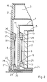
- the cryostat 1 shown in FIG. 1 has a nitrogen tank 3, a shield 4 and a helium tank 5, which contains a superconducting magnet 6, inside a jacket 2, viewed from the outside inwards.
- the shield 4 is fastened to the end faces 7 of the nitrogen tank 3 by means of tension rods 8, just as the helium tank 5 is fastened to the shield 4 by means of tension rods 9.
- the helium tank 5 is connected to the nitrogen tank 3 by at least one axially extending tension rod 10.
- the nitrogen tank 3 is also attached to the end faces 11 of the jacket 2 by means of tie rods 12.
- the tie rods 8, 9, 10, and 12 each have at their ends a connection point 13, via which they are fixed to the component to be fastened.
- the pull rod 9 connecting the helium tank 5 to the shield 4 is fastened with its upper end 14 to the inside of the end wall 15 of the radiation shield 4 via the connection point 13.
- the lower end 16 of the tension rod 9 is fixed via a connection point 13 on the outside of the end wall 17 of the helium tank 5.
- the pull rod 8 connecting the radiation shield 4 to the nitrogen tank 3 is also fastened in the same way.
- the connection point 13, in which the upper end 18 of the tension rod 8 is fixed is not fastened directly to the end wall 19 of the nitrogen tank 3, but to the end wall 20, which bears with its outer edge 21 on the end wall 19 of the nitrogen tank 3.
- the lower end 22 of the tension rod 8 is fixed in a bearing piece 23 which is fastened to an inner jacket part 24 of the shield 4.
- the attachment of the ends 14, 16, 18 and 22 of the tie rods 9 and 8 in the connection points 13 and in the bearing piece 23 is carried out in that the ends of the tie rods 8 and 9 are provided with an externally threaded tie rod 25, which in corresponding threaded holes Connection points 13 and the bearing piece 23 are screwed.
- the tension rods 8 and 9 can each be fastened to the inside of the outer component during the assembly of the cryostat 1 before the inner component is inserted into the outer, and finally the fastening to the outside of the inner component can be done by a recess 26 and 27, respectively in the outer component. These recesses 26 and 27 can be easily closed if necessary.
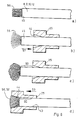
- connection point 13 shows an enlarged representation of an embodiment of a connection point 13 in cross section, into which a tie rod 25 with a tension rod fixed therein is inserted.
- the tie rod is cylindrical and has a first cylindrical region 28 which has a smaller diameter than the second cylindrical region 29. The area 28 is separated from the area 29 via a shoulder 30.
- the tie rod 25 has a bore, generally designated 31, which comprises a cylindrical region 32 and an adjoining region 33 which widens conically towards the outside. The end of one of the tension rods 8, 9, 10 or 12 is inserted into this bore 31, the end of the tension rod also being widened in the conically widening region 33, which will be discussed in more detail later.
- the tie rod 25 itself is inserted into a recess 34 of the connection point 13, which is open in the direction of the top 35 and in the direction of one of its vertical sides 36 so that the tie rod 25 can be inserted into the recess 34, the region 28 of the tie rod 25 finally coming to rest in a recess 37 which is provided in the bottom 38 of the connection point 13 in such a way that projections 39 and 40 cover the region 29 reach under the tie rod 25 at paragraph 30.
- the vertical side 36 is designed such that it partially surrounds the tie rod 25 inserted in the recess 34 in the circumferential direction. The tie rod 25 thus lies securely in the recess 34, so that forces can be introduced in a targeted manner from the tension rod via the connection point 13 to components attached to it.
- the tie rod 25 shown in FIG. 4 is a further embodiment, the tie rod 25 now consisting of an inner sleeve 41 and an outer sleeve 42 coaxially encompassing the inner sleeve 41.
- the inner sleeve 41 is designed in accordance with the tie rod 25 shown in FIG. 3 with a first cylindrical region 28 and a second cylindrical region 29 adjoining it via a shoulder 30 and having a larger diameter than the region 28.
- the inner sleeve 41 also has a cylindrical bore 43 and an adjoining, conically widening bore 44. The end 45 of one of the tension rods 8, 9, 10 or 12 is inserted into these bores 43 and 44.
- the outer sleeve 42 surrounding the inner sleeve 41 has on its outside an external thread 46 extending over part of the axial length and is provided with a tool engagement surface 47, for example a hexagon, which extends over the remaining axial length of the outer surface of the outer sleeve 42 at the other Free end 45 of the tie rod facing side extends.
- the bore 48 of the outer sleeve 42 is designed such that it passes from an area 49 with a larger diameter via a shoulder 50 to an area 51 with a smaller diameter, the diameter of the area 49 being the diameter corresponds to the area 29 of the inner sleeve 41, and the area 28 of the inner sleeve 41 lies in the area 51 with play. Paragraphs 30 and 50 abut each other.
- the outer sleeve 42 is advantageously made of brass and the inner sleeve 41 is made of a plastic, preferably of the plastic of the plastic tension rod.
- the position of the free end 45 of the tension rod with respect to the connection point 13 can be set exactly by the screw-in depth, the screwing movement resulting from the two-part design of the tie rod is not transmitted to the inner sleeve 41 and thus to the tension rod.
- the tie rod 25 shown in FIG. 5 is likewise made in two parts, the inner sleeve 41 being in the form of a ball pin 52 made of metal and the outer sleeve 42 representing a ball socket 53 for the ball 54 of the ball pin 52.
- the ball 54 is followed by a cylindrical extension 55 corresponding to the region 28, which has the cylindrical bore 43, whereas the ball 54 is provided with the conically widening bore 44. If the outer sleeve 42 is now screwed into a threaded bore of a connection point 13 via its external thread 46, the forces of the connection point are only introduced axially into the pull rod 8, 9, 10 or 12.
- the tie rod 25 is axially pushed onto the tie rod in the direction of arrow 57 such that its conically widening bore 44 points in the direction of the free end 45 of the tie rod, and the tie rod 25 is spaced from the end 45. Then the glass fibers 56 projecting beyond the end 45 are fanned out or spread. The glass fibers can additionally be corrugated, melted or the like deformed.
- an adhesive 58 preferably an epoxy adhesive, as shown in FIG.
- the tie rod 25 finally becomes in the direction of arrow 59 in this way over the glass fibers 56 wetted with adhesive 58 moved that these fanned ends of the glass fibers 56 come to lie in the conically widening bore 44.
- the circumferential region of the tension rod can also have been provided with an adhesive over a certain distance 60, this distance 60 finally coming to rest in the cylindrical bore 43 of the tie rod 25, whereby an additional connection of the tie rod to the tie rod 25 is created.
Description
Die Erfindung betrifft einen Kryostat, insbesondere für supraleitende Magnete, mit ineinandergeschachtelten Bauteilen, von denen eines eine äußere Hülle und mindestens ein anderes ein in der Hülle angeordnetes Gefäß zur Aufnahme eines Kühlmittels bildet, und mit die Bauteile verbindenden Zugstäben, mit denen jeweils ein inneres Bauteil an dem benachbarten, weiter außen liegenden Bauteil aufgehängt ist, welche Zugstäbe als runde, mit Glasfasern oder Aramidfasern verstärkte Kunststoffstäbe ausgebildet sind, an ihren beiden Enden Zuganker aufweisen und über die Zuganker an dem jeweiligen Bauteil befestigt sind, wobei die Enden der Zugstäbe von Glasfasern oder Aramidfasern gebildet werden und die Enden in einer sich erweiternden Bohrung im Zuganker festgelegt sind. Die Erfindung betrifft außerdem ein Verfahren zur Herstellung derartiger Zugmittel.The invention relates to a cryostat, in particular for superconducting magnets, with nested components, one of which forms an outer shell and at least another forms a vessel arranged in the shell for receiving a coolant, and to the connecting rods connecting the components, with each of which an inner component is suspended from the adjacent, more external component, which tie rods are designed as round plastic rods reinforced with glass fibers or aramid fibers, have tie rods at both ends and are fastened to the respective component via the tie rods, the ends of the tie rods being made of glass fibers or Aramid fibers are formed and the ends are fixed in an expanding hole in the tie rod. The invention also relates to a method for producing such traction means.
Bei Kryostaten für supraleitende Magnete, die allgemein den vorstehend beschriebenen Aufbau haben, bereitet die Ausbildung der Zugmittel, die in der Regel als Zugstäbe ausgebildet sind, besondere Probleme. Diese Zugstäbe müssen eine hohe Zugfestigkeit haben, um die relativ großen Massen sicher zu tragen, und zugleich eine geringe Wärmeleitfähigkeit aufweisen, um den Wärmetransport in das Innere eines Kryostaten möglichst klein zu halten. Sie sollen zugleich einfach zu fertigen und zu montieren sein und im Kryostaten möglichst wenig Platz einnehmen, da die zu ihrer Unterbringung erforderlichen Räume erheblich zum Bauvolumen eines solchen Kryostaten beitragen können.In the case of cryostats for superconducting magnets, which generally have the structure described above, the design of the traction means, which are generally designed as traction rods, poses particular problems. These tension rods must have a high tensile strength in order to safely carry the relatively large masses, and at the same time have a low thermal conductivity in order to keep the heat transport into the interior of a cryostat as small as possible. At the same time, they should be easy to manufacture and assemble and take up as little space as possible in the cryostat, since the rooms required for their accommodation can make a considerable contribution to the construction volume of such a cryostat.
Es sind Kunststoffstäbe bekannt, Z.B. aus WO-8604016 (PCT/GB 86/000 14), die mit direktionalen Glasfasern verstärkt sind. Diese Zugstäbe weisen den Vorteil auf, daß sie die erforderliche Zugfestigkeit besitzen, ohne im Kryostaten übermäßig viel Platz in Anspruch zu nehmen. An ihren Enden sind diese Zugstäbe mit Zuganker versehen, über die die Kräfte eingeleitet werden. Eine innige Verbindung zwischen dem Zugstab und dem Zuganker wird dadurch erreicht, daß am Ende des Kunststoffstabes die Glasfasern zu einer Schlaufe ausgebildet sind, und die Schlaufe am Ende des Kunststoffstabes übersteht. Der Zuganker weist eine sich konisch erweiternde Bohrung auf, in die das Ende des Zugstabes derart ein- und hindurchgeführt wird, daß die Glasfaserschlaufe das erweiterte Ende überragt. In die überstehende Schlaufe wird nun ein Keil eingesetzt die Glasfasern mit dem Keil in die sich in Zugrichtung verjüngende Bohrung eingezogen und schließlich die Glasfasern in dieser Lage ausgehärtet.Plastic rods are known, e.g. from WO-8604016 (PCT / GB 86/000 14), which are reinforced with directional glass fibers. These tension rods have the advantage that they have the required tensile strength without taking up too much space in the cryostat. At their ends, these tension rods are provided with tie rods via which the forces are introduced. An intimate connection between the tension rod and the tie rod is achieved in that the glass fibers are formed into a loop at the end of the plastic rod and the loop protrudes at the end of the plastic rod. The tie rod has a conically widening bore into which the end of the tension rod is inserted and passed in such a way that the glass fiber loop projects beyond the enlarged end. A wedge is now inserted into the protruding loop, the glass fibers are drawn with the wedge into the bore tapering in the pulling direction and finally the glass fibers are cured in this position.
Diese hochfeste Verbindung von Zuganker und Zugstab weist aber den Nachteil auf, daß die Enden der Zugstäbe mit Schlaufen aus Glasfasern versehen sein müssen, was zum einen kostenintensiv, zum anderen aufwendig ist, da eine Vielzahl von Zugstäben mit unterschiedlichen Längen in einem Kryostaten Einsatz finden und für jede Länge ein Zugstab mit Schlaufen an seinen Enden hergestellt werden muß. Aufgrund der unterschiedlichen Materialien von Zuganker, Keil- und Kunststoffstab besteht ein weiterer Nachteil darin, daß wegen deren unterschiedlichen Ausdehnungskoeffizienten keine gute Oberflächenverbindung zwischen dem Zugstab und dem Zuganker hergestellt werden kann. Die Bruchsicherheit dieser Verbindung ist daher begrenzt.However, this high-strength connection of tie rod and tie rod has the disadvantage that the ends of the tie rods must be provided with loops made of glass fibers, which is cost-intensive on the one hand, and complex on the other hand, since a large number of tie rods are used different lengths are used in a cryostat and a tension rod with loops at its ends must be produced for each length. Due to the different materials of tie rod, wedge and plastic rod, there is a further disadvantage that, because of their different expansion coefficients, a good surface connection between the tie rod and the tie rod cannot be produced. The security against breakage of this connection is therefore limited.
Demgemäß liegt der Erfindung die Aufgabe zugrunde, Zugmittel für Kryostaten zu schaffen, die auf einfache und kostengünstige Weise unter Einhaltung enger Toleranzen herstellbar sind, einen geringen Platzbedarf haben und zugleich eine höhere Bruchsicherheit aufweisen.Accordingly, the object of the invention is to create traction means for cryostats which can be produced in a simple and inexpensive manner while adhering to narrow tolerances, require little space and at the same time are more break-proof.
Diese Aufgabe wird nach der erfindungsgemäßen Vorrichtung dadurch gelöst, daß die die Enden der Zugstäbe bildenden Glasfasern oder Aramidfasern an den Zugstabenden enden und aufgefächert in der Bohrung des Zugankers festgelegt sind, wobei ein jedes Faserende mit einem Klebstoff umgeben ist und daß die Bohrung des Zugankers über einen ersten Bereich zylindrisch und über den restlichen Bereich sich konisch erweiternal verläuft.This object is achieved by the device according to the invention in that the glass fibers or aramid fibers forming the ends of the tension rods end at the ends of the tension rod and are fanned out in the bore of the tie rod, each end of the fiber being surrounded with an adhesive and in that the bore of the tie rod is over a first area is cylindrical and extends conically over the remaining area.
Gemäß der Erfindung werden die Zugmittel mit Zuganker versehen, wobei die Zuganker eine sich erweiternde Bohrung aufweisen. Die Enden der Zugmittel, die von direktionalen Glasfasern gebildet werden, sind aufgefächert bzw. gespreizt, so daß das Ende der Zugmittel eine größere Querschnittsfläche als der restliche Körper des Zugmittels aufweist, und sind die Enden mit einem Klebstoff versehen, der jede einzelne Glasfaser umgibt und einhüllt. Das Zugmittel ist schließlich derart im Zuganker angeordnet, daß es dessen Bohrung durchgreift und das von den aufgefächerten und mit dem Klebstoff getränkte Ende der Glasfasern sich in dem erweiterten Ende der Bohrung befindet. Nach dem Aushärten des Klebstoffes können aufgrund der großflächigen und direkten Verbindung des Klebstoffes mit den Glasfaserenden sehr hohe Zugkräfte über den Zuganker auf die Zugmittel eingeleitet werden. Bei dieser Belastung wird der Klebstoff auf Scherung und Druck belastet, so daß der Klebstoff zwischen den Fasern eingeklemmt wird, da die Zugrichtung des Zugmittels in Richtung des sich verjüngenden Endes der Bohrung des Zugankers erfolgt, und somit eine Verdrängung des Klebstoffs bewirkt wird. Selbst bei einer beschädigten Verbindung von Zuganker und Zugmittel kann diese noch Kräfte übertragen, da der Verdrängung des Klebstoffes aus dem Raum zwischen den Fasern der Selbsthemmungseffekt entgegenwirkt. Diese Verbindung überträgt also auch noch nach dem Überschreiten der durch Lastspitzen hervorgerufenen Bruchdehnung Zugkräfte mit Sicherheit. Vorteilhaft besteht der Zuganker aus Kunststoff und ist mit direktionalen oder bidirektionalen Glasfasern verstärkt.According to the invention, the traction means are provided with tie rods, the tie rods having an expanding bore. The ends of the traction means, which are formed by directional glass fibers, are spread out so that the end of the traction means has a larger cross-sectional area than the rest of the body of the traction means, and the ends are provided with an adhesive which surrounds each individual glass fiber and envelops. Finally, the traction means is arranged in the tie rod in such a way that it passes through its bore and the end of the glass fibers that is fanned out and soaked with the adhesive is located in the enlarged end of the bore. After the adhesive has hardened, very large tensile forces can be introduced via the tie rod onto the traction means due to the large-area and direct connection of the adhesive to the glass fiber ends will. At this load, the adhesive is subjected to shear and pressure, so that the adhesive is pinched between the fibers, since the pulling direction of the traction means takes place in the direction of the tapered end of the bore of the tie rod, and thus a displacement of the adhesive is effected. Even if the tie rod and traction element are damaged, this can still transmit forces, since the displacement of the adhesive from the space between the fibers counteracts the self-locking effect. This connection therefore reliably transmits tensile forces even after the breaking elongation caused by load peaks has been exceeded. The tie rod is advantageously made of plastic and is reinforced with directional or bidirectional glass fibers.
Als besonders vorteilhaft hat sich eine Form der Glasfasern enthaltenden Zugmittel erwiesen, bei der diese als runde mit direktionalen Glasfasern verstärkte Kunststoffstäbe ausgebildet sind. Derartige glasfaserverstärkte Kunststoffstäbe sind als Massenware erhältlich, die nur noch auf die gewünschte Länge zugeschnitten werden müssen, und bei denen lediglich die Enden von dem die Glasfasern umgebenden Harz befreit werden müssen, so daß die Glasfasern nach dem Einführen des Kunststoffstabes in die Bohrung des Zugankers aufgefächert und mit einem Klebstoff versehen werden können. Bevorzugt weist das engere Ende der Bohrung einen dem Querschnitt des Kunststoffstabs entsprechenden Querschnitt auf.A form of the traction means containing glass fibers has proven to be particularly advantageous, in which they are designed as round plastic rods reinforced with directional glass fibers. Such glass fiber reinforced plastic rods are available in bulk, which only need to be cut to the desired length, and in which only the ends of the resin surrounding the glass fibers have to be freed, so that the glass fibers fanned out after the insertion of the plastic rod into the bore of the tie rod and can be provided with an adhesive. The narrower end of the bore preferably has a cross section corresponding to the cross section of the plastic rod.
Bei einer anderen vorteilhaften Ausführung ist vorgesehen, daß die Zugmittel als Kevlar-Kordeln ausgebildet sind. Auch diese Kevlar-Kordeln, bestehend aus Aramidfasern, können sehr hohe Zugkräfte übertragen und weisen den Vorteil auf, daß sie für die Herstellung der Verbindung mit dem Zuganker keiner Vorbehandlung bedürfen. Die Kevlar-Kordel wird lediglich über das engere Ende der Bohrung des Zugankers in diesen soweit eingeführt, daß sie das erweiterte Ende überragt. Nach dem Auffächern der überragenden Enden der Aramidfasern und dem Zusatz von Klebstoff wird das überragende Ende in die bohrung des Zugankers wieder eingezogen, so daß in dieser Lage der Klebstoff aushärten kann.In another advantageous embodiment it is provided that the traction means are designed as Kevlar cords. These Kevlar cords, consisting of aramid fibers, can transmit very high tensile forces and have the advantage that they do not require any pretreatment for the connection to the tie rod. The Kevlar cord is only inserted into the tie rod through the narrower end of the tie rod, that it towers over the extended end. After fanning out the protruding ends of the aramid fibers and adding adhesive, the protruding end is drawn back into the hole in the tie rod, so that the adhesive can harden in this position.
Wie bereits erwähnt, muß die von den Zugmitteln übertragene Wärmemenge möglichst klein gehalten werden. Für die Wärmeübertragung ist nicht nur die Wärmeleitfähigkeit des Zugmittels selbst von Bedeutung, sondern auch die Wärmeübertragung von den Bauteilen, an denen das Zugmittel befestigt ist, auf die Zug mittel. Dabei haben die in dem erfindungsgemäßen Kryostaten verwendeten Zugmittel den Vorteil, daß wegen der geringen Dicke der Zugmittel die Kontaktfläche zwischen den Zugmitteln und den daran befestigten Zugankern relativ klein ist, so daß der Wärmeübergang durch Wärmeleitung verhältnismäßig klein ist. Trotz der geringen Dicke besitzen die Zugmittel vorteilhaft eine ausreichende Zugfestigkeit.As already mentioned, the amount of heat transferred by the traction means must be kept as small as possible. For the heat transfer not only the thermal conductivity of the traction means itself is important, but also the heat transfer from the components to which the traction means is attached to the traction means. The pulling means used in the cryostat according to the invention have the advantage that, because of the small thickness of the pulling means, the contact area between the pulling means and the tie rods attached to them is relatively small, so that the heat transfer by heat conduction is relatively small. Despite the small thickness, the traction means advantageously have sufficient tensile strength.
Bevorzugt ist der Zuganker mit einer sich zu einer Bohrungsöffnung hin konisch erweiternden Bohrung versehen. Eine andere vorteilhafte Ausführungsform sieht vor, daß die Bohrung des Zugankers über einen ersten Bereich zylindrisch und über den restlichen Bereich sich konisch erweiternd verläuft. Der zylindrische Bereich der Bohrung kann dem Querschnitt des Zugmittels angepaßt sein, wohingegen der konisch sich erweiternde Bereich derart ausgebildet ist, daß dieser die aufgefächerten Enden der direktionalen Glasfasern die in Klebstoff eingebettet sind, vollständig aufnimmt. Bevorzugt kann auch der an das aufgefächerte Ende sich anschließende, im zylindrischen Bereich der Bohrung des Zugankers sich befindende Abschnitt des Zugmittels in diesen zylindrischen Bereich eingeklebt sein. Bei einer Zugbelastung des Zugmittels treten demnach im zylindrischen Bereich Scherkräfte zwischen dem Zugmittel und dem Zuganker und im konisch sich erweiternden Bereich der Bohrung Druck- und Scherkräfte auf. Dies hat den Vorteil, daß, da die Verbindung nicht auf reine Scherung beansprucht wird, wesentlich höhere Belastungen übertragen werden können.The tie rod is preferably provided with a bore which widens conically towards a bore opening. Another advantageous embodiment provides that the bore of the tie rod extends cylindrically over a first area and widens conically over the remaining area. The cylindrical region of the bore can be adapted to the cross section of the traction means, whereas the conically widening region is designed in such a way that it completely receives the fanned out ends of the directional glass fibers which are embedded in adhesive. The section of the traction means adjoining the fanned-out end and located in the cylindrical region of the bore of the tie rod can also be glued into this cylindrical region. When the traction means is subjected to tensile stress, shear forces therefore occur between the traction means and the tie rod in the cylindrical region and in the conically widening area of the bore pressure and shear forces. This has the advantage that, since the connection is not subjected to pure shear, significantly higher loads can be transmitted.
Bei einer anderen Ausbildung ist vorgesehen, daß der Zuganker mit einer sich stufenförmig erweiternden Bohrung versehen ist. Diese Bohrung ist ebenfalls einfach herzustellen und kann mit einer dem Einsatzzweck entsprechenden Anzahl von Stufen versehen werden.Another embodiment provides that the tie rod is provided with a step-widening bore. This hole is also easy to manufacture and can be provided with a number of steps corresponding to the intended use.
Bei einem bevorzugten Beispiel eines Zugankers ist dieser zylinderförmig ausgebildet, verläuft die Bohrung koaxial und ist seine Außenseite mit einem Außengewinde versehen. Dieser Zuganker überträgt die auf ihn eingeleiteten Kräfte gleichmäßig auf den in der koaxialen Bohrung festgelegten Zugstab. Weiterhin weist dieser Zuganker den Vorteil auf, da er in einer Gewindebohrung festgelegt wird, daß über die Einschraubtiefe des Zugankers einfach die Lage des zu befestigenden Bauteils eingestellt werden kann. Eine Handhabung des Zugankers wird über eine Werkzeugangriffsfläche erreicht, die an seiner Außenseite vorgesehen ist. An dieser Werkzeugangriffsfläche kann z.B. ein Gabelschlüssel angesetzt werden, über den der bolzenartig ausgebildete Zuganker in ein Sackloch eingeschraubt wird.In a preferred example of a tie rod, it is cylindrical, the bore runs coaxially and its outside is provided with an external thread. This tie rod transfers the forces applied to it evenly to the tension rod defined in the coaxial bore. Furthermore, this tie rod has the advantage that it is fixed in a threaded hole that the position of the component to be fastened can be easily adjusted via the screw-in depth of the tie rod. Handling of the tie rod is achieved via a tool engagement surface which is provided on its outside. On this tool contact surface, e.g. a wrench can be used, through which the bolt-shaped tie rod is screwed into a blind hole.
Ein anderer Zuganker ist vorteilhaft mehrteilig ausgebildet, wobei der Zuganker eine das Zugmittel umgebende Innenhülse und eine die Innenhülse umgebende und sich an dieser axial abstützende Außenhülse aufweist. Bei diesem Zuganker wird das Ende des Zugmittels mit der Innenhülse verbunden, wohingegen die Außenhülse als freibewegliches Bauteil ausgebildet ist, und demnach relativ zur Innenhülse Drehbewegungen ausführen kann, diese jedoch axial abstützt. Beim Festlegen der Außenhülse an dem zu haltenden Bauteil, z.B. durch Einschrauben, werden somit die Schraubbewegungen der Außenhülse nicht auf die Innenhülse und somit auch nicht auf den Zugstab übertragen, wodurch schädigende Torsionsbeanspruchungen vermieden werden. Axiale Kräfte werden jedoch über die Abstützung und die Innenhülse auf das Zugmittel eingeleitet.Another tie rod is advantageously designed in several parts, the tie rod having an inner sleeve surrounding the traction means and an outer sleeve surrounding the inner sleeve and axially supported thereon. In this tie rod, the end of the traction means is connected to the inner sleeve, whereas the outer sleeve is designed as a freely movable component and can therefore perform rotational movements relative to the inner sleeve, but supports it axially. When fixing the outer sleeve to the component to be held, for example by screwing in, are thus the screwing movements of the outer sleeve are not transmitted to the inner sleeve and thus not to the tension rod, whereby damaging torsional stresses are avoided. However, axial forces are applied to the traction device via the support and the inner sleeve.
Die axiale Abstützung von Außen- und Innenhülse wird vorteilhaft dadurch erreicht, daß die Innenhülse an ihrem dem freien Ende des Zugmittels zugewandten Ende einen radial sich erweiternden Absatz und die Außenhülse einen den Absatz hintergreifenden, sich radial nach innen erstreckenden Vorsprung aufweist.The axial support of the outer and inner sleeves is advantageously achieved in that the inner sleeve has a radially widening shoulder at its end facing the free end of the traction means and the outer sleeve has a radially inward projection that engages behind the shoulder.
Bevorzugt besteht die Innenhülse aus Kunststoff, insbesondere dem die Glasfasern einbettenden Kunststoff des Zugstabes, und die Außenhülse aus Metall, insbesondere Messing. Hierdurch wird eine stabile Befestigung des Zugankers z.B. in einer Gewindebohrung ermöglicht und eine hochfeste Oberflächenverbindung von Innenhülse und Zugstabgewährt, da deren Materialien den gleichen Ausdehnungskoeffizienten aufweisen. Weiterhin ist der Klebstoff vorteilhaft ein Epoxidklebstoff.The inner sleeve is preferably made of plastic, in particular the plastic of the tension rod embedding the glass fibers, and the outer sleeve is made of metal, in particular brass. This ensures a stable attachment of the tie rod e.g. in a threaded hole and a high-strength surface connection between the inner sleeve and the tension rod, since their materials have the same expansion coefficient. Furthermore, the adhesive is advantageously an epoxy adhesive.
Die oben genannte Aufgabe wird nach dem erfindungsgemäßen Verfahren dadurch gelöst, daß die Glasfaserenden an den Enden der Zugmittel von Kunststoff befreit werden, diese Glasfaserenden in die Bohrung des Zugankers soweit eingeführt werden, daß sie über dessen erweitertes Ende hinausragen, daß die Glasfaserenden aufgefächert und mit Klebstoff versehen, wieder in die Bohrung eingezogen und in dieser ausgehärtet werden.The above object is achieved by the process according to the invention in that the glass fiber ends at the ends of the traction means are freed of plastic, these glass fiber ends are inserted into the bore of the tie rod to such an extent that they protrude beyond its enlarged end in such a way that the glass fiber ends are fanned out and with Apply the adhesive, pull it back into the hole and harden it.
Dieses Verfahren sieht vor, daß bei glasfaserverstärkten Kunst3stoffstäben an den Enden die Glasfasern freigelegt werden, so daß diese nach dem Einführen in die Bohrung der Zuganker aufgefächert werden können, wobei sich der Durchmesser des Glasfaserbündels vergrößert, und die Glasfaserenden nach dem Auffächern mit einem Klebstoff versehen werden und schließlich soweit in den Zuganker wieder eingezogen werden, daß sie in der sich erweiternden Bohrung zu liegen kommen. In dieser Lage härtet nun der Klebstoff aus und verbindet die Glasfaserenden zu einem Pfropf, der sicher in der in Zugrichtung sich verengenden Bohrung des Zugankers liegt.This method provides that in the case of glass fiber reinforced plastic rods, the glass fibers are exposed at the ends so that they can be fanned out after being inserted into the bore of the tie rods, the diameter of the glass fiber bundle increasing and the glass fiber ends after the fanning out be provided with an adhesive and finally pulled back into the tie rod until they come to rest in the widening hole. In this position, the adhesive hardens and connects the glass fiber ends to a graft that lies securely in the hole of the tie rod that narrows in the direction of pull.
Bei Kevlar-Kordeln müssen die Glasfasern nach dem Durchtritt durch die Bohrung des Zugankers lediglich aufgefächert, mit Klebstoff versehen und in die Bohrung wieder eingezogen werden. Es erübrigt sich hier die vorherige Säuberung der Glasfaserenden von anhaftendem Kunststoff.With Kevlar cords, the glass fibers only have to be fanned out after passing through the hole in the tie rod, provided with adhesive and pulled back into the hole. The previous cleaning of the glass fiber ends from adhering plastic is unnecessary here.
Bevorzugt können die aufgefächerten Glasfaserenden zusätzlich noch textoriert, gestaucht oder dgl. verformt werden. Durch diese zusätzliche Verformung der Glasfaserenden wird ein späteres Herausziehen dieser aus dem in der Bohrung des Zugankers festliegenden Pfropf zusätzlich verhindert.The fanned-out glass fiber ends can preferably also be textured, compressed or the like. This additional deformation of the glass fiber ends also prevents them from later being pulled out of the plug fixed in the hole in the tie rod.
Weitere Vorteile, Merkmale und Einzelheiten ergeben sich aus der nachfolgenden Beschreibung, in der unter Bezugnahme auf die Zeichnung, Ausführungsbeispiele im einzelnen erläutert sind. Dabei zeigen:
- Fig.1
- teilweise in Seitenansicht und teilweise im Schnitt einen nach der Erfindung ausgebildeten Kryostaten in schematischer Darstellung;
- Fig.2
- einen Abschnitt des Kryostaten nach Fig.1 in vergrößertem Maßstab;
- Fig.3
- einen Querschnitt durch eine Ausführungsform einer Anschlußstelle eines Zugstabs in nochmal vergrößertem Maßstab;
- Fig.4 + 5
- einen Querschnitt durch beispielhafte Ausführungen eines Zugankers; und
- Fig.6 a-d
- in schematischer Darstellung vier Arbeitsschritte bei der Herstellung der Verbindung eines Zugstabs mit einem Zuganker.
- Fig. 1
- partly in side view and partly in section a cryostat designed according to the invention in a schematic representation;
- Fig. 2
- a portion of the cryostat according to Figure 1 on an enlarged scale;
- Fig. 3
- a cross section through an embodiment of a connection point of a tension rod in a further enlarged scale;
- Fig. 4 + 5
- a cross section through exemplary embodiments of a tie rod; and
- Fig. 6 ad
- a schematic representation of four steps in the manufacture of the connection of a tension rod with a tie rod.
Der in Fig.1 dargestellte Kryostat 1 weist innerhalb eines Mantels 2 von außen nach innen gesehen einen Stickstofftank 3, einen Schild 4 und einen Heliumtank 5 auf, der einen supraleitenden Magnet 6 enthält. Der Schild 4 ist an den Stirnseiten 7 des Stickstofftankes 3 mittels Zugstäben 8 befestigt, wie auch der Heliumtank 5 an dem Schild 4 mittels Zugstäben 9 befestigt ist. Ferner ist der Heliumtank 5 mit dem Stickstofftank 3 durch wenigstens einen sich axial erstreckenden Zugstab 10 verbunden. Schließlich ist auch der Stickstofftank 3 an den Stirnflächen 11 des Mantels 2 durch Zugstäbe 12 befestigt. Die Zugstäbe 8, 9, 10, und 12 weisen an ihren Enden jeweils eine Anschlußstelle 13 auf, über die sie an dem zu befestigenden Bauteil festgelegt sind.The
Wie aus Fig.2 ersichtlich, ist der den Heliumtank 5 mit dem Schild 4 verbindende Zugstab 9 mit seinem oberen Ende 14 über die Anschlußstelle 13 an der Innenseite der Stirnwand 15 des Strahlungsschildes 4 befestigt. Ebenso ist das untere Ende 16 des Zugstabes 9 über eine Anschlußstelle 13 an der Außenseite der Stirnwand 17 des Heliumtanks 5 festgelegt. In der gleichen Weise ist auch der den Strahlungsschild 4 mit dem Stickstofftank 3 verbindende Zugstab 8 befestigt. Allerdings ist die Anschlußstelle 13, in der das obere Ende 18 des Zugstabs 8 festgelegt ist nicht direkt an der Stirnwand 19 des Stickstofftanks 3 befestigt, sondern an der Stirnwand 20, die mit ihrem äußeren Rand 21 an der Stirnwand 19 des Stickstofftanks 3 anliegt. Das untere Ende 22 des Zugstabs 8 ist in einem Lagerstück 23 festgelegt, das an einem inneren Mantelteil 24 des Schildes 4 befestigt ist.As can be seen from FIG. 2, the
Die Befestigung der Enden 14, 16, 18 und 22 der Zugstäbe 9 und 8 in den Anschlußstellen 13 bzw. im Lagerstück 23 erfolgt dadurch, daß die Enden der Zugstäbe 8 und 9 mit ein Außengewinde aufweisenden Zugankern 25 versehen sind, die in entsprechende Gewindebohrungen der Anschlußstellen 13 bzw. des Lagerstücks 23 eingeschraubt sind. Die Zugstäbe 8 und 9 können bei der Montage des Kryostaten 1 jeweils an der Innenseite des äußeren Bauteils befestigt werden, bevor das innere Bauteil in das äußere eingeführt wird, und schließlich kann die Befestigung an der Außenseite des inneren Bauteils durch eine Aussparung 26 bzw. 27 im äußeren Bauteil hindurch erfolgen. Diese Aussparungen 26 und 27 können bei Bedarf leicht verschlossen werden.The attachment of the
Die Fig.3 zeigt in vergrößerter Darstellung eine Ausführungsform einer Anschlußstelle 13 im Querschnitt, in die ein Zuganker 25 mit einem darin festgelegten Zugstab eingesetzt ist. Der Zuganker ist zylinderförmig ausgebildet und weist einen ersten zylinderförmigen Bereich 28 auf, der gegenüber dem zweiten zylinderförmigen Bereich 29 einen geringeren Durchmesser aufweist. Der Bereich 28 ist vom Bereich 29 über einen Absatz 30 getrennt. Weiterhin weist der Zuganker 25 eine insgesamt mit 31 bezeichnete Bohrung auf, die einen Zylinderförmigen Bereich 32 und einen sich daran anschließenden Bereich 33 umfaßt, der sich nach außen hin konisch erweitert. In diese Bohrung 31 ist das Ende einer der Zugstäbe 8, 9, 10 oder 12 eingesetzt, wobei in dem sich konisch erweiternden Bereich 33 das Ende des Zugstabs ebenfalls erweitert ist, worauf später noch näher eingegangen wird. Der Zuganker 25 selbst ist in eine Ausnehmung 34 der Anschlußstelle 13 eingesetzt, die in Richtung der Oberseite 35 und in Richtung einer ihrer vertikalen Seiten 36 offen ausgebildet ist, so daß der Zuganker 25 in die Ausnehmung 34 eingeführt werden kann, wobei schließlich der Bereich 28 des Zugankers 25 in einer Ausnehmung 37 zu liegen kommt, die im Boden 38 der Anschlußstelle 13 derart vorgesehen ist, daß Vorsprünge 39 und 40 den Bereich 29 des Zugankers 25 am Absatz 30 untergreifen. Die vertikale Seite 36 ist derart ausgebildet, daß sie den in der Ausnehmung 34 eingesetzten Zuganker 25 in Umfangsrichtung teilweise umschließt. Der Zuganker 25 liegt also sicher in der Ausnehmung 34, so daß Kräfte gezielt vom Zugstab über die Anschlußstelle 13 auf daran befestigte Bauteile eingeleitet werden können.3 shows an enlarged representation of an embodiment of a
Bei dem in der Fig.4 gezeigten Zuganker 25 handelt es sich um eine weitere Ausführungsform, wobei nun der Zuganker 25 aus einer Innenhülse 41 und einer die Innenhülse 41 koaxial umgreifenden Außenhülse 42 besteht. Die Innenhülse 41 ist entsprechend dem in der Fig.3 dargestellten Zuganker 25 mit einem ersten zylindrischen Bereich 28 und einem sich über einen Absatz 30 daran anschließenden zweiten zylindrischen Bereich 29, der einen größeren Durchmesser als der Bereich 28 aufweist, ausgebildet. Ebenfalls weist die Innenhülse 41 eine zylindrische Bohrung 43 und eine sich daran anschließende, konisch erweiternde Bohrung 44 auf. In diese Bohrungen 43 und 44 ist das Ende 45 einer der Zugstäbe 8, 9, 10 oder 12 eingesetzt. Die die Innenhülse 41 umgebende Außenhülse 42 weist an ihrer Außenseite ein über einen Teil der axialen Länge sich erstreckendes Außengewinde 46 auf und ist mit einer Werkzeugangriffsfläche 47, z.B. einem Sechskant versehen, die sich über die restliche axiale Länge der Außenoberfläche der Außenhülse 42 an deren dem freien Ende 45 des Zugstabs abgewandten Seite erstreckt. Die Bohrung 48 der Außenhülse 42 ist derart ausgebildet, daß sie von einem Bereich 49 mit einem größeren Durchmesser über einen Absatz 50 zu einem Bereich 51 mit geringerem Durchmesser übergeht, wobei der Durchmesser des Bereichs 49 dem Durchmesser des Bereichs 29 der Innenhülse 41 entspricht, und der Bereich 28 der Innenhülse 41 mit Spiel im Bereich 51 liegt. Dabei liegen die Absätze 30 und 50 aneinander an. Vorteilhaft besteht die Außenhülse 42 aus Messing und ist die Innenhülse 41 aus einem Kunststoff, bevorzugt aus dem Kunststoff des Kunststoffzugstabes gebildet.The
Wird nun der Zuganker 25 über ein an der Werkzeugangriffsfläche 47 angesetztes Werkzeug in eine Gewindebohrung einer Anschlußstelle 13 eingeschraubt, so kann die Lage des freien Endes 45 des Zugstabs bezüglich der Anschlußstelle 13 exakt durch die Einschraubtiefe eingestellt werden, wobei sich die Schraubbewegung aufgrund der zweiteiligen Ausführung des Zugankers nicht auf die Innenhülse 41 und somit auf den Zugstab überträgt.If the
Der in Fig.5 gezeigte Zuganker 25 ist ebenfalls zweiteilig ausgeführt, wobei die Innenhülse 41 in Form eines aus Metall bestehenden Kugelbolzens 52 ausgebildet ist und die Außenhülse 42 eine Kugelpfanne 53 für die Kugel 54 des Kugelbolzens 52 darstellt. An die Kugel 54 schließt sich ein dem Bereich 28 entsprechender zylindrischer Fortsatz 55 an, der die zylindrische Bohrung 43 aufweist, wohingegen die Kugel 54 mit der sich konisch erweiternden Bohrung 44 versehen ist. Wird nun die Außenhülse 42 über ihr Außengewinde 46 in eine Gewindebohrung einer Anschlußstelle 13 eingeschraubt, so werden die Kräfte der Anschlußstelle ausschließlich axial in den Zugstab 8, 9, 10 oder 12 eingeleitet.The
Nachfolgend wird anhand dem in den Figuren 6 a-d gezeigten schematischen Ablauf die Herstellung einer Verbindung eines Endes eines Zugstabs 8, 9, 10 oder 12 mit einem Zuganker 25 beschrieben. Das Ende 45 des Zugstabs wird so vorbereitet, daß das Harz von den direktionalen Glasfasern 56 gelöst und entfernt wird, so daß die Glasfasern 56 den Kunststoff des Zugstabs axial überragen. Anstelle des in der Fig.6 gezeigten mit direktionalen Glasfasern verstärkten Kunstsoffstabs können auch Kevlar-Kordeln verwendet werden, bei denen dieser Schritt der Lösung und Entfernung des Harzes entfällt. Gemäß der Fig.6b wird der Zuganker 25 derart in Richtung des Pfeiles 57 auf den Zugstab axial aufgeschoben, daß dessen sich konisch erweiternde Bohrung 44 in Richtung des freien Endes 45 des Zugstabes zeigt, und der Zuganker 25 zum Ende 45 beabstandet ist. Sodann werden die das Ende 45 überragenden Glasfasern 56 aufgefächert oder gespreizt. Die Glasfasern können zusätzlich noch gewellt, angeschmolzen oder dergleichen verformt werden. Nach dem Aufbringen eines Klebstoffes 58, vorzugsweise eines Epoxidklebstoffes, wie in der Fig.6c dargestellt, der die freien Enden der Glasfasern 56 vollständig umfließt und einhüllt, wird schließlich der Zuganker 25 in Richtung des Pfeiles 59 derart über die mit Klebstoff 58 benetzten Glasfasern 56 verschoben, daß diese aufgefächerten Enden der Glasfasern 56 in der konisch sich erweiternden Bohrung 44 zu liegen kommen. Zusätzlich kann über eine gewisse Wegstrecke 60 der Umfangsbereich des Zugstabs ebenfalls mit einem Klebstoff versehen worden sein, wobei diese Wegstrecke 60 schließlich in der zylindrischen Bohrung 43 des Zugankers 25 zu liegen kommt, wodurch eine zusätzliche Verbindung des Zugstabs mit dem Zuganker 25 geschaffen wird. Nach dem Aushärten des Klebstoffs 58 ist eine dauerhafte und hochbelastbare Verbindung zwischen dem Zugstab und dem Zuganker 25 geschaffen, da im Bereich der Wegstrecke 60 die Verbindung auf Scherung, und der Klebstoff 58 zwischen den Enden der Glasfasern 56 ebenfalls auf Scherung und zusätzlich auf Druck beansprucht wird, wodurch aufgrund einer Selbsthemmung ein Herausziehen der Glasfasern 56 aus dem Klebstoff 58 verhindert wird. Selbst bei einer beschädigten Verbindung können noch Kräfte über eine gewisse Wegstrecke aufgenommen werden, so daß die Festigkeit der Verbindung bei einer Beschädigung nicht plötzlich absinkt und dadurch unkontrollierbare Lageänderungen der im Kryostat 1 über die Zugstäbe 8, 9, 10 und 12 festgelegten Behälter auftritt.In the following, the establishment of a connection of one end of a
Claims (12)
- Cryostat in particular for superconducting magnets with nested construction parts, from which one forms an outer shell and at least one other a vessel arranged within the shell for receiving a coolant, and with tension rods connecting the construction parts, with which each inner construction part is suspended on the neighboring more outer lying construction part, the tension bars being round fiber glass or aramide fiber reinforced plastic bars and exhibiting, on both ends, tension anchors, and by means of the tension anchors are attached to the corresponding construction part, whereby the ends of the tension bars are formed from fiber glass or aramide fibers and the ends are secured in a widened bore in the tension anchor, characterized in that the fiber glass or aramide fibers (56) which form the ends (45) of the tension bars, terminate at the ends of the tension bars (45) and are fanned out and secured in the bore (31) of the tension anchor (25), whereby each fiber end is surrounded with glue (58) and the bore (31) of the tension anchor (25) is cylindrical in a first region (32) and conically widening over the remaining region (33).
- Cryostat according to claim 1, characterized in that the tension anchor (25) is provided with a step-shaped widening bore.
- Cryostat according to one or more of the previous claims, characterized in that the tension anchor (25) is cylindrically shaped, the bore (31) runs coaxially, and its outer side is provided with an outer thread (46).
- Cryostat according to claim 3, characterized in that the outer side of the tension anchor (25) is provided with a tool engagement surface (47).
- Cryostat according to one or more of the preceding claims, characterized in that the tension anchor (25) exhibits an inner bushing (41) which surrounds the tension bar and an outer bushing (42) which surrounds and is axially supported (offsets 30 and 50) by the inner bushing.
- Cryostat according to claim 5, characterized in that the inner bushing (41) exhibits, on its free end (45) which faces the tension bar, a radially widening offset (30) and the outer bushing (42) exhibits a projection (39 and 40) which supports the offset (30) from below and extends radially inward.
- Cryostat according to claim 5 or 6, characterized in that the inner bushing (41) exhibits the same expansion coefficient as the tension bar.
- Cryostat according to one or more of the claims 5 to 7, characterized in that the inner bushing (41) is comprised of plastic, in particular from the plastic of the tension bar embedding the fiber glass or aramide fibers.
- Cryostat according to one or more of the claims 5 through 8, characterized in that the outer bushing (42) is made from metal, in particular brass.
- Cryostat according to one or more of the preceding claims, characterized in that the glue (58) is an epoxy glue.
- Method for the production of a tension means for a cryostat, in particular for superconducting magnets with nested construction parts, of which one forms an outer shell and at least one other a vessel, arranged inside the shell, for receiving a coolant, and with tension means fastening the construction parts, by means of which each inner construction part is suspended from the neighboring outer lying construction part, the tension means being round and having fiber glass or aramide fiber reinforced plastic bars, and exhibiting at their ends tension anchors, and via the tension anchors are secured to the corresponding construction part, characterized in that the fiber glass or aramide fibers are freed from plastic at the ends of the tension bars, that these aramide or fiber glass ends are introduced sufficiently far into the bore of the tension anchor that they project out beyond its widened end, and that the fiber glass or aramide fibers, fanned out and provided with glue, are pulled back into the bore and are hardened therein.
- Method according to claim 11, characterized in that the fanned-out fiber glass or aramide fiber ends are textured, buckled or similarly deformed.
Applications Claiming Priority (2)
| Application Number | Priority Date | Filing Date | Title |
|---|---|---|---|
| DE19893915578 DE3915578C1 (en) | 1989-05-12 | 1989-05-12 | |
| DE3915578 | 1989-05-12 |
Publications (3)
| Publication Number | Publication Date |
|---|---|
| EP0397168A2 EP0397168A2 (en) | 1990-11-14 |
| EP0397168A3 EP0397168A3 (en) | 1991-02-06 |
| EP0397168B1 true EP0397168B1 (en) | 1993-12-08 |
Family
ID=6380546
Family Applications (1)
| Application Number | Title | Priority Date | Filing Date |
|---|---|---|---|
| EP19900108810 Expired - Lifetime EP0397168B1 (en) | 1989-05-12 | 1990-05-10 | Cryostat |
Country Status (3)
| Country | Link |
|---|---|
| US (1) | US5140823A (en) |
| EP (1) | EP0397168B1 (en) |
| DE (2) | DE3915578C1 (en) |
Families Citing this family (12)
| Publication number | Priority date | Publication date | Assignee | Title |
|---|---|---|---|---|
| DE29613966U1 (en) * | 1996-08-13 | 1997-12-11 | Autokuehler Gmbh & Co Kg | Heat exchanger, in particular a condenser for the air conditioning system of a motor vehicle |
| US6416215B1 (en) | 1999-12-14 | 2002-07-09 | University Of Kentucky Research Foundation | Pumping or mixing system using a levitating magnetic element |
| GB2345745B (en) * | 1999-01-16 | 2003-03-05 | Oxford Magnet Tech | Improvements in or relating to suspension systems |
| US6758593B1 (en) | 2000-10-09 | 2004-07-06 | Levtech, Inc. | Pumping or mixing system using a levitating magnetic element, related system components, and related methods |
| US6570476B1 (en) * | 2002-07-17 | 2003-05-27 | General Electric Company | Thermal shield suspension for superconductive magnets |
| AT504239A1 (en) * | 2006-09-27 | 2008-04-15 | Rebernik Matthias Dipl Ing Dr | CRYOBE CONTAINER AND METHOD FOR THE PRODUCTION THEREOF |
| KR20090057284A (en) * | 2006-09-27 | 2009-06-04 | 마티아스 레베르닉 | Container for receiving media and/or units which are to be stored at low temperatures |
| GB2449652B (en) * | 2007-05-30 | 2009-06-10 | Siemens Magnet Technology Ltd | Suspension rod tensioning arrangements |
| US20140166662A1 (en) * | 2012-12-13 | 2014-06-19 | Hebeler Corporation | Suspension System for a Cryogenic Vessel |
| GB2517746B (en) * | 2013-08-30 | 2016-09-14 | Ubh Int Ltd | Storage tank suspension member and storage tank for storage of cryogenic liquid |
| US10928007B2 (en) * | 2016-05-04 | 2021-02-23 | Linde Aktiengesellschaft | Transport container |
| FR3081756A1 (en) * | 2018-05-31 | 2019-12-06 | Albea Services | METHOD FOR MANUFACTURING A PUMP GUIDE ROD |
Family Cites Families (12)
| Publication number | Priority date | Publication date | Assignee | Title |
|---|---|---|---|---|
| US3328229A (en) * | 1963-11-06 | 1967-06-27 | Dow Chemical Co | Method and apparatus for attaching load bearing members to low strength bodies |
| FR1472691A (en) * | 1966-03-28 | 1967-03-10 | Bliss E W Co | Fixing device on a clip at the end of a tape |
| CH571267A5 (en) * | 1974-10-23 | 1975-12-31 | Klaey Hans | Glass fibre-reinforced plastics tension rod for insulator - anchored in end fitting of insulator for transmission of tensile forces to all glass fibres |
| DE2610915A1 (en) * | 1976-03-16 | 1977-09-22 | Artur Rudolf | ELEMENT FOR INTRODUCING TENSIONING FORCE IN FIBER-REINFORCED PLASTIC PARTS |
| CH640973A5 (en) * | 1978-06-02 | 1984-01-31 | Micafil Ag | Method for producing an insulating rod, which is resistant to tension, compression and torsion and has attachment fittings, and a device for carrying out the method |
| DE2903787C2 (en) * | 1979-02-01 | 1983-11-03 | Messerschmitt-Bölkow-Blohm GmbH, 8000 München | Suspension device for a low-temperature tank arranged in a thermally insulated manner in an external container |
| US4483904A (en) * | 1983-04-26 | 1984-11-20 | Church Kenneth S | Connecting fibre reinforced pultrusions |
| GB8500495D0 (en) * | 1985-01-09 | 1985-02-13 | Oxford Magnet Tech | Epoxy bonded glass fibre rods |
| JPS6283597A (en) * | 1985-10-08 | 1987-04-17 | Toshiba Corp | Adiabatic supporting device for very low temperature vessel |
| US4848103A (en) * | 1987-04-02 | 1989-07-18 | General Electric Company | Radial cryostat suspension system |
| US4781034A (en) * | 1987-06-10 | 1988-11-01 | Universities Research Association, Inc. | Cryogenic support system |
| DE3724569A1 (en) * | 1987-07-24 | 1989-02-02 | Spectrospin Ag | CRYOSTAT |
-
1989
- 1989-05-12 DE DE19893915578 patent/DE3915578C1/de not_active Expired - Lifetime
-
1990
- 1990-05-10 DE DE90108810T patent/DE59003752D1/en not_active Expired - Lifetime
- 1990-05-10 US US07/521,732 patent/US5140823A/en not_active Expired - Lifetime
- 1990-05-10 EP EP19900108810 patent/EP0397168B1/en not_active Expired - Lifetime
Also Published As
| Publication number | Publication date |
|---|---|
| DE3915578C1 (en) | 1990-11-15 |
| DE59003752D1 (en) | 1994-01-20 |
| EP0397168A2 (en) | 1990-11-14 |
| EP0397168A3 (en) | 1991-02-06 |
| US5140823A (en) | 1992-08-25 |
Similar Documents
| Publication | Publication Date | Title |
|---|---|---|
| EP2162634B1 (en) | Arrangement for connecting an elongate element to a further component | |
| DE102016221309B4 (en) | Support structure for a power transmission element, aircraft reaction linkage, flight control surface drive unit, | |
| EP0397168B1 (en) | Cryostat | |
| DE1261358B (en) | Method for producing a tensile strength connection between a metal fitting and a smooth rod or tube made of plastic material | |
| DE60017433T2 (en) | CONNECTION DEVICE | |
| EP3586018B1 (en) | Fastening device and fastening assembly | |
| DE102010046518A1 (en) | Rotor blade or rotor segment for a wind turbine | |
| DE102016007663A1 (en) | Tubular fiber composite body with integrated stepless length adjustment | |
| DE4006028C2 (en) | Connecting bolts and arrangement of components | |
| DE4027230C2 (en) | Screw socket connection | |
| EP1598563B1 (en) | Connector system | |
| EP3204633A1 (en) | Wind turbine rotor blade | |
| DE19645467A1 (en) | Force application device | |
| DE1063428B (en) | End armoring for control ropes and coupling device for control ropes reinforced in this way, which are subject to tension and pressure and are guided in a flexible cover | |
| AT410035B (en) | INTERCEPTION DEVICE FOR AN OPTICAL CABLE | |
| DE102019108910A1 (en) | Multi-part adjustment element for a tolerance compensation arrangement | |
| DE2619830C3 (en) | Tow bars for automobiles | |
| DE1947332U (en) | FASTENING ELEMENT MADE OF TOAELASTIC MATERIAL. | |
| DE102021129101A1 (en) | Spacers and transport arrangement | |
| EP0641945A1 (en) | Control cable for actuation of vehicle devices | |
| DE3539392C2 (en) | ||
| CH664803A5 (en) | ARRANGEMENT FOR TRANSMITTING A FORCE AND METHOD FOR PRODUCING A ANCHOR BAR. | |
| DE102011013783A1 (en) | Connection arrangement for bamboo cane of baby carriage, has reinforcing plates and/or reinforcing plate sections pressed by clamping device against bamboo cane outer wall, where clamping device includes clamping element | |
| DE3139037A1 (en) | Fastening arrangement for helical tension springs | |
| DE19845937C1 (en) | Fastening for bearing cap to trunnion |
Legal Events
| Date | Code | Title | Description |
|---|---|---|---|
| PUAI | Public reference made under article 153(3) epc to a published international application that has entered the european phase |
Free format text: ORIGINAL CODE: 0009012 |
|
| AK | Designated contracting states |
Kind code of ref document: A2 Designated state(s): CH DE DK FR GB LI NL |
|
| PUAL | Search report despatched |
Free format text: ORIGINAL CODE: 0009013 |
|
| RBV | Designated contracting states (corrected) |
Designated state(s): CH DE FR GB LI NL |
|
| AK | Designated contracting states |
Kind code of ref document: A3 Designated state(s): CH DE DK FR GB LI NL |
|
| 17P | Request for examination filed |
Effective date: 19910209 |
|
| 17Q | First examination report despatched |
Effective date: 19920819 |
|
| GRAA | (expected) grant |
Free format text: ORIGINAL CODE: 0009210 |
|
| AK | Designated contracting states |
Kind code of ref document: B1 Designated state(s): CH DE FR GB LI NL |
|
| PG25 | Lapsed in a contracting state [announced via postgrant information from national office to epo] |
Ref country code: NL Effective date: 19931208 |
|
| GBT | Gb: translation of ep patent filed (gb section 77(6)(a)/1977) |
Effective date: 19931214 |
|
| REF | Corresponds to: |
Ref document number: 59003752 Country of ref document: DE Date of ref document: 19940120 |
|
| ET | Fr: translation filed | ||
| NLV1 | Nl: lapsed or annulled due to failure to fulfill the requirements of art. 29p and 29m of the patents act | ||
| PLBE | No opposition filed within time limit |
Free format text: ORIGINAL CODE: 0009261 |
|
| STAA | Information on the status of an ep patent application or granted ep patent |
Free format text: STATUS: NO OPPOSITION FILED WITHIN TIME LIMIT |
|
| 26N | No opposition filed | ||
| REG | Reference to a national code |
Ref country code: GB Ref legal event code: IF02 |
|
| REG | Reference to a national code |
Ref country code: CH Ref legal event code: PFA Free format text: SPECTROSPIN AG TRANSFER- BRUKER BIOSPIN AG |
|
| REG | Reference to a national code |
Ref country code: FR Ref legal event code: CD |
|
| PGFP | Annual fee paid to national office [announced via postgrant information from national office to epo] |
Ref country code: FR Payment date: 20040423 Year of fee payment: 15 |
|
| PGFP | Annual fee paid to national office [announced via postgrant information from national office to epo] |
Ref country code: GB Payment date: 20040428 Year of fee payment: 15 |
|
| PGFP | Annual fee paid to national office [announced via postgrant information from national office to epo] |
Ref country code: CH Payment date: 20040729 Year of fee payment: 15 |
|
| PG25 | Lapsed in a contracting state [announced via postgrant information from national office to epo] |
Ref country code: GB Free format text: LAPSE BECAUSE OF NON-PAYMENT OF DUE FEES Effective date: 20050510 |
|
| PG25 | Lapsed in a contracting state [announced via postgrant information from national office to epo] |
Ref country code: LI Free format text: LAPSE BECAUSE OF NON-PAYMENT OF DUE FEES Effective date: 20050531 Ref country code: CH Free format text: LAPSE BECAUSE OF NON-PAYMENT OF DUE FEES Effective date: 20050531 |
|
| REG | Reference to a national code |
Ref country code: CH Ref legal event code: PL |
|
| GBPC | Gb: european patent ceased through non-payment of renewal fee |
Effective date: 20050510 |
|
| PG25 | Lapsed in a contracting state [announced via postgrant information from national office to epo] |
Ref country code: FR Free format text: LAPSE BECAUSE OF NON-PAYMENT OF DUE FEES Effective date: 20060131 |
|
| REG | Reference to a national code |
Ref country code: FR Ref legal event code: ST Effective date: 20060131 |
|
| PGFP | Annual fee paid to national office [announced via postgrant information from national office to epo] |
Ref country code: DE Payment date: 20090527 Year of fee payment: 20 |
|
| PG25 | Lapsed in a contracting state [announced via postgrant information from national office to epo] |
Ref country code: DE Free format text: LAPSE BECAUSE OF EXPIRATION OF PROTECTION Effective date: 20100510 |