EP3366879A1 - Tool coupler with rotating coupling method for top drive - Google Patents
Tool coupler with rotating coupling method for top drive Download PDFInfo
- Publication number
- EP3366879A1 EP3366879A1 EP18158050.7A EP18158050A EP3366879A1 EP 3366879 A1 EP3366879 A1 EP 3366879A1 EP 18158050 A EP18158050 A EP 18158050A EP 3366879 A1 EP3366879 A1 EP 3366879A1
- Authority
- EP
- European Patent Office
- Prior art keywords
- ring coupler
- coupler
- housing
- component
- central shaft
- Prior art date
- Legal status (The legal status is an assumption and is not a legal conclusion. Google has not performed a legal analysis and makes no representation as to the accuracy of the status listed.)
- Granted
Links
- 238000010168 coupling process Methods 0.000 title claims abstract description 46
- 230000013011 mating Effects 0.000 claims abstract description 101
- 230000008878 coupling Effects 0.000 claims abstract description 45
- 238000005859 coupling reaction Methods 0.000 claims abstract description 45
- 238000000034 method Methods 0.000 claims abstract description 45
- 230000000295 complement effect Effects 0.000 claims abstract description 18
- 238000005553 drilling Methods 0.000 description 15
- 238000012546 transfer Methods 0.000 description 15
- 238000004519 manufacturing process Methods 0.000 description 9
- 230000003287 optical effect Effects 0.000 description 7
- 238000003780 insertion Methods 0.000 description 6
- 230000037431 insertion Effects 0.000 description 6
- 230000007246 mechanism Effects 0.000 description 6
- 239000012530 fluid Substances 0.000 description 5
- 230000008901 benefit Effects 0.000 description 3
- 238000004891 communication Methods 0.000 description 3
- 230000036316 preload Effects 0.000 description 3
- 230000008569 process Effects 0.000 description 3
- 230000015572 biosynthetic process Effects 0.000 description 2
- 238000010276 construction Methods 0.000 description 2
- 238000005755 formation reaction Methods 0.000 description 2
- 239000003550 marker Substances 0.000 description 2
- VNWKTOKETHGBQD-UHFFFAOYSA-N methane Chemical compound C VNWKTOKETHGBQD-UHFFFAOYSA-N 0.000 description 2
- 241000239290 Araneae Species 0.000 description 1
- 239000004215 Carbon black (E152) Substances 0.000 description 1
- 238000005452 bending Methods 0.000 description 1
- 230000009286 beneficial effect Effects 0.000 description 1
- 230000005540 biological transmission Effects 0.000 description 1
- 150000001875 compounds Chemical class 0.000 description 1
- 238000012790 confirmation Methods 0.000 description 1
- 239000010779 crude oil Substances 0.000 description 1
- 229930195733 hydrocarbon Natural products 0.000 description 1
- 150000002430 hydrocarbons Chemical group 0.000 description 1
- 238000012423 maintenance Methods 0.000 description 1
- 238000003801 milling Methods 0.000 description 1
- 239000003345 natural gas Substances 0.000 description 1
- 238000010248 power generation Methods 0.000 description 1
- 230000004044 response Effects 0.000 description 1
- 238000004513 sizing Methods 0.000 description 1
- 239000012207 thread-locking agent Substances 0.000 description 1
Images


Classifications
-
- E—FIXED CONSTRUCTIONS
- E21—EARTH DRILLING; MINING
- E21B—EARTH DRILLING, e.g. DEEP DRILLING; OBTAINING OIL, GAS, WATER, SOLUBLE OR MELTABLE MATERIALS OR A SLURRY OF MINERALS FROM WELLS
- E21B17/00—Drilling rods or pipes; Flexible drill strings; Kellies; Drill collars; Sucker rods; Cables; Casings; Tubings
- E21B17/02—Couplings; joints
- E21B17/04—Couplings; joints between rod or the like and bit or between rod and rod or the like
- E21B17/046—Couplings; joints between rod or the like and bit or between rod and rod or the like with ribs, pins, or jaws, and complementary grooves or the like, e.g. bayonet catches
-
- F—MECHANICAL ENGINEERING; LIGHTING; HEATING; WEAPONS; BLASTING
- F16—ENGINEERING ELEMENTS AND UNITS; GENERAL MEASURES FOR PRODUCING AND MAINTAINING EFFECTIVE FUNCTIONING OF MACHINES OR INSTALLATIONS; THERMAL INSULATION IN GENERAL
- F16B—DEVICES FOR FASTENING OR SECURING CONSTRUCTIONAL ELEMENTS OR MACHINE PARTS TOGETHER, e.g. NAILS, BOLTS, CIRCLIPS, CLAMPS, CLIPS OR WEDGES; JOINTS OR JOINTING
- F16B7/00—Connections of rods or tubes, e.g. of non-circular section, mutually, including resilient connections
- F16B7/18—Connections of rods or tubes, e.g. of non-circular section, mutually, including resilient connections using screw-thread elements
- F16B7/187—Connections of rods or tubes, e.g. of non-circular section, mutually, including resilient connections using screw-thread elements with sliding nuts or other additional connecting members for joining profiles provided with grooves or channels
Definitions
- Embodiments of the present invention generally relate to equipment and methods for coupling a top drive to one or more tools.
- the coupling may transfer both axial load and torque bi-directionally from the top drive to the one or more tools.
- a wellbore is formed to access hydrocarbon-bearing formations (e.g ., crude oil and/or natural gas) or for geothermal power generation by the use of drilling. Drilling is accomplished by utilizing a drill bit that is mounted on the end of a tool string. To drill within the wellbore to a predetermined depth, the tool string is often rotated by a top drive on a drilling rig. After drilling to a predetermined depth, the tool string and drill bit are removed, and a string of casing is lowered into the wellbore. Well construction and completion operations may then be conducted.
- hydrocarbon-bearing formations e.g ., crude oil and/or natural gas
- the attachments between the tools and the top drive typically include mechanical, electrical, optical, hydraulic, and/or pneumatic connections, conveying torque, load, data, signals, and/or power.
- Threaded connections also suffer from the risk of cross threading. When the threads are not correctly aligned before torque is applied, cross threading may damage the components. The result may be a weak or unsealed connection, risk of being unable to separate the components, and risk of being unable to re-connect the components once separated. Therefore, threading (length) compensation systems may be used to provide accurate alignment and/or positioning of components having threaded connections prior to application of make-up (or break-out) torque. Conventional threading compensation systems may require unacceptable increase in component length. For example, if a hydraulic cylinder positions a threaded component, providing threading compensation with the cylinder first requires an increase in the cylinder stroke length equal to the length compensation path.
- the cylinder housing must also be increased by the same amount to accommodate the cylinder stroke in a retracted position. So adding conventional threading compensation to a hydraulic cylinder would require additional component space up to twice the length compensation path length. For existing rigs, where vertical clearance and component weight are important, this can cause problems.
- the present invention generally relates to equipment and methods for coupling a top drive to one or more tools.
- the coupling may transfer both axial load and torque bi-directionally from the top drive to the one or more tools.
- a tool coupler includes a first component comprising: a ring coupler having mating features and rotatable between a first position and a second position; an actuator functionally connected to the ring coupler to rotate the ring coupler between the first position and the second position; and a second component comprising a profile complementary to the ring coupler.
- a method of coupling a first component to a second component includes inserting a central shaft of the first component into a housing of the second component; rotating a ring coupler around the central shaft; and engaging mating features of the ring coupler with a profile, wherein the profile is on an outside of the central shaft or an inside of the housing.
- a method of coupling a first component to a second component includes inserting a central shaft of the first component into a housing of the second component; rotating a first ring coupler around the central shaft; and clamping a profile using the first ring coupler and a second ring coupler, wherein the profile is on an outside of the central shaft or an inside of the housing.
- a method of coupling a first component to a second component includes inserting a central shaft of the first component into a housing of the second component; rotating a first ring coupler around the central shaft; and moving a second ring coupler vertically relative to the housing to engage a profile, wherein the profile is on an outside of the central shaft or an inside of the housing.
- the present invention provides equipment and methods for coupling a top drive to one or more tools.
- the top drive may include a control unit, a drive unit, and a tool coupler.
- the coupling may transfer torque bi-directionally from the top drive through the tool coupler to the one or more tools.
- the coupling may provide mechanical, electrical, optical, hydraulic, and/or pneumatic connections.
- the coupling may conveying torque, load, data, signals, and/or power.
- axial loads of tool strings may be expected to be several hundred tons, up to, including, and sometimes surpassing 750 tons.
- Required torque transmission may be tens of thousands of foot-pounds, up to, including, and sometimes surpassing 100 thousand foot-pounds.
- Embodiments disclosed herein may provide axial connection integrity, capable to support high axial loads, good sealability, resistance to bending, high flow rates, and high flow pressures.
- Some of the many benefits provided by embodiments of this disclosure include a tool coupler having a simple mechanism that is low maintenance. Benefits also include a reliable method to transfer full bi-directional torque, thereby reducing the risk of accidental breakout of threaded connections along the tool string.
- the moving parts of the mechanism may be completely covered. During coupling or decoupling, no turning of exposed parts of the coupler or tool may be required. Coupling and decoupling is not complicated, and the connections may be release by hand as a redundant backup.
- Embodiments of this disclosure may also provide a fast, hands-free method to connect and transfer power from the top drive to the tools. Embodiments may also provide automatic connection for power and data communications.
- Embodiments may also provide threading (length) compensation to reduce impact, forces, and/or damage at the threads.
- Embodiments may provide confirmation of orientation and/or position of the components, for example a stab-in signal. During make-up or break-out, threading compensation may reduce the axial load at the thread and therefore the risk of damage of the thread.
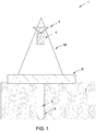
- FIG. 1 illustrates a drilling system 1, according to embodiments of the present disclosure.
- the drilling system 1 may include a drilling rig derrick 3d on a drilling rig floor 3f.
- drilling rig floor 3f is at the surface of a subsurface formation 7, but the drilling system 1 may also be an offshore drilling unit, having a platform or subsea wellhead in place of or in addition to rig floor 3f.
- the derrick may support a hoist 5, thereby supporting a top drive 4.
- the hoist 5 may be connected to the top drive 4 by threaded couplings.
- the top drive 4 may be connected to a tool string 2. At various times, top drive 4 may support the axial load of tool string 2.
- the top drive 4 may be connected to the tool string 2 by threaded couplings.
- the rig floor 3f may have an opening through which the tool string 2 extends downwardly into a wellbore 9. At various times, rig floor 3f may support the axial load of tool string 2.
- top drive 4 may provide torque to tool string 2, for example to operate a drilling bit near the bottom of the wellbore 9.
- the tool string 2 may include joints of drill pipe connected together, such as by threaded couplings.
- top drive 4 may provide right hand (RH) torque or left hand (LH) torque to tool string 2, for example to make up or break out joints of drill pipe.
- Power and/or signals may be communicated between top drive 4 and tool string 2.
- pneumatic, hydraulic, electrical, optical, or other power and/or signals may be communicated between top drive 4 and tool string 2.
- the top drive 4 may include a control unit, a drive unit, and a tool coupler.
- the tool coupler may utilize threaded connections.
- the tool coupler may be a combined multi-coupler (CMC) or quick connector to support load and transfer torque with couplings to transfer power (hydraulic, electric, data, and/or pneumatic).
- CMC combined multi-coupler
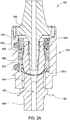
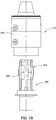
- FIG 2A illustrates a tool coupler 100 for a top drive system ( e.g., top drive 4 in Figure 1 ) according to embodiments described herein.
- tool coupler 100 includes a receiver assembly 110 and a tool adapter 150.
- the receiver assembly 110 generally includes a housing 120, one or more ring couplers 130, and one or more actuators 140 functionally connected to the ring couplers 130.
- each ring coupler 130 may be a single component forming a complete ring, multiple components connected together to form a complete ring, a single component forming a partial ring, or multiple components connected together to form one or more partial rings.
- the housing 120 may be connected to a top drive ( e.g., top drive 4 in Figure 1 ).
- the actuators 140 may be fixedly connected to the housing 120.
- the actuators 140 may be connected with bearings (e.g ., a spherical bearing connecting the actuator 140 to the housing, and another spherical bearing connecting the actuator 140 to the ring coupler 130.
- the ring couplers 130 may be connected to the housing 120 such that the ring couplers 130 may rotate 130-r relative to the housing 120.
- the ring couplers 130 may be connected to the housing 120 such that the ring couplers 130 may move translationally 130-t ( e.g., up or down) relative to the housing 120.
- the tool adapter 150 generally includes a tool stem 160, a profile 170 that is complementary to the ring couplers 130 of the receiver assembly 110, and a central shaft 180.
- the tool stem 160 generally remains below the receiver assembly 110.
- the tool stem 160 connects the tool coupler 100 to the tool string 2.
- the central shaft 180 generally inserts into the housing 120 of the receiver assembly 110.
- the housing 120 may include a central stem 190 with an outer diameter less than or equal to an inner diameter of central shaft 180.
- the central stem 190 and central shaft 180 may share a central bore 165 ( e.g. providing fluid communication through the tool coupler 100).
- central bore 165 is a sealed mud channel.
- central bore 165 provides a fluid connection (e.g., a high pressure fluid connection).
- the profile 170 may be disposed on the outside of the central shaft 180.
- the profile 170 may include convex features on the outer surface of central shaft 180.
- the housing 120 may have mating features 125 that are complementary to profile 170.
- the housing mating features 125 may be disposed on an interior of the housing 120.
- the housing mating features 125 may include convex features on an inner surface of the housing 120.
- the actuators 140 may cause the ring couplers 130 to rotate 130-r around the central shaft 180, and/or the actuators 140 may cause the ring couplers 130 to move translationally 130-t relative to central shaft 180.
- Rotation 130-r of the ring coupler 130 may be less than a full turn, less than 180 °, or even less than 30°.
- tool coupler 100 may transfer torque and/or load between the top drive and the tool.
- Figure 2B illustrates a tool coupler 100' having a reverse configuration of components as illustrated in Figure 2A .
- tool coupler 100' includes a receiver assembly 110' and a tool adapter 150'.
- the tool adapter 150' generally includes a housing 120', one or more ring couplers 130', and one or more actuators 140' functionally connected to the ring couplers 130'.
- the housing 120' may be connected to the tool string 2.
- the actuators 140' may be fixedly connected to the housing 120'.
- the ring couplers 130' may be connected to the housing 120' such that the ring couplers 130' may rotate and/or move translationally relative to the housing 120'.
- the receiver assembly 110' generally includes a drive stem 160', a profile 170' that is complementary to the ring couplers 130' of the tool adapter 150', and a central shaft 180'.
- the drive stem 160' generally remains above the tool adapter 150'.
- the drive stem 160' connects the tool coupler 100 to a top drive ( e.g ., top drive 4 in Figure 1 ).
- the central shaft 180' generally inserts into the housing 120' of the tool adapter 150'.
- the housing 120' may include a central stem 190' with an outer diameter less than or equal to an inner diameter of central shaft 180'.
- the central stem 190' and central shaft 180' may share a central bore 165' ( e.g . providing fluid communication through the tool coupler 100').
- the profile 170' may be disposed on the outside of the central shaft 180'.
- the profile 170' may include convex features on the outer surface of central shaft 180'.
- the housing 120' may have mating features 125' that are complementary to profile 170'.
- the housing mating features 125' may be disposed on an interior of the housing 120'.
- the housing mating features 125' may include convex features on an inner surface of the housing 120'.
- the actuators 140' may cause the ring couplers 130' to rotate and/or to move translationally relative to central shaft 180'.
- tool coupler 100' may transfer torque and/or load between the top drive and the tool. Consequently, for each embodiment described herein, it should be understood that the components of the tool couplers could be usefully implemented in reverse configurations.
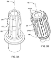
- the profile 170 may include splines 275 distributed on the outside of central shaft 180.
- the splines 275 may run vertically along central shaft 180.
- "vertically”, “up”, and “down” as used herein refer to the general orientation of top drive 4 as illustrated in Figure 1 . In some instances, the orientation may vary somewhat, in response to various operational conditions.
- the splines 275 may (as shown) or may not (not shown) be distributed symmetrically about the central axis 185 of the central shaft 180.
- the width of each spline 275 may (as shown) or may not (not shown) match the width of the other splines 275.
- the splines 275 may run contiguously along the outside of central shaft 180 (as shown in Figure 3A ).
- the splines 275 may include two or more discontiguous sets of splines distributed vertically along the outside of central shaft 180 (e.g., splines 275-a and 275-b in Figure 3B ; splines 275-a, 275-b, and 275-c in Figure 3C ).
- Figure 3A illustrates six splines 275 distributed about the central axis 185 of the central shaft 180.
- Figures 3B and 3C illustrate ten splines 275 distributed about the central axis 185 of the central shaft 180. It should be appreciated that any number of splines may be considered to accommodate manufacturing and operational conditions.
- Figure 3C also illustrates a stop surface 171 to be discussed below.
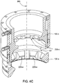
- one or more of the ring couplers 130 may have mating features 235 on an interior thereof.
- the ring coupler mating features 235 may include convex features on an inner surface of the ring coupler 130.
- the ring coupler 130 may have cogs 245 distributed on an outside thereof (further discussed below). In some embodiments, the cogs 245 may be near the top of the ring coupler 130 (not shown).
- the mating features 235 may be complementary with splines 275 from the respective central shaft 180. For example, during coupling or decoupling of receiver assembly 110 and tool adapter 150, the mating features 235 may slide between the splines 275.
- the mating features 235 may run vertically along the interior of ring coupler 130.
- the mating features 235 may (as shown) or may not (not shown) be distributed symmetrically about the central axis 285 of the ring coupler 130.
- the width of each mating feature 235 may (as shown) or may not (not shown) match the width of the other mating features 235.
- the mating features 235 may run contiguously along the interior of the ring couplers 130 (as shown in Figures 4A and 4B ).
- the mating features 235 may include two or more discontiguous sets of mating features distributed vertically along the interior of the ring couplers 130.
- ring coupler 130-c includes mating features 235-c, while ring coupler 130-s includes mating features 235-s which are below mating features 235-c.
- such discontiguous sets of mating features may be rotationally coupled.
- ring coupler 130-c may be fixed to ring coupler 130-s, thereby rotationally coupling mating features 235-c with mating features 235-s.
- Figure 4A illustrates six mating features 235 distributed about the central axis 285 of the ring couplers 130.
- Figures 4B and 4C illustrates ten mating features 235 distributed about the central axis 285 of the central shaft 180. It should be appreciated that any number of mating features may be considered to accommodate manufacturing and operational conditions.
- Figure 4C also illustrates a stop surface 131 to be discussed below.
- housing 120 may have mating features 125 on an interior thereof.
- the housing mating features 125 may be complementary with splines 275 from the respective central shaft 180.
- the mating features 125 may slide between the splines 275.
- the mating features 125 may run vertically along the interior of housing 120.
- the housing mating features 125 may be generally located lower on the housing 120 than the operational position of ring couplers 130.
- the mating features 125 may (as shown) or may not (not shown) be distributed symmetrically about the central axis 385 of the housing 120.
- the width of each mating feature 125 may (as shown) or may not (not shown) match the width of the other mating features 125.
- the mating features 125 may run contiguously along the interior of the housing 120 (as shown).
- one or more actuators 140 may be functionally connected to ring couplers 130.
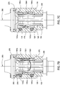
- Figure 5A illustrates an embodiment having three ring couplers 130 and two actuators 140.
- Figure 5B illustrates an embodiment showing one ring coupler 130 and two actuators 140. It should be appreciated that any number of ring couplers and actuators may be considered to accommodate manufacturing and operational conditions.
- the actuators 140 illustrated in Figure 5A are worm drives, and the actuators illustrated in Figure 5B are hydraulic cylinders. Other types of actuators 140 may be envisioned to drive motion of the ring couplers 130 relative to the housing 120.
- Adjacent to each actuator 140 in Figure 5A are ring couplers 130 having cogs 245 distributed on an outside thereof (better seen in Figure 4A ).
- Gearing of the actuators 140 may mesh with the cogs 245.
- the two actuators 140 in Figure 5A can thereby independently drive the two adjacent ring couplers 130 to rotate 130-r about central axis 285.
- the two actuators 140 in Figure 5B (i.e., the hydraulic cylinders) are both connected to the same ring coupler 130.
- the hydraulic cylinders are each disposed in cavity 115 in the housing 120 to permit linear actuation by the hydraulic cylinder.
- the two actuators 140 in Figure 5B can thereby drive the ring coupler 130 to rotate 130-r about central axis 285.
- ring coupler 130 shown in Figure 4B includes pin holes 142 positioned and sized to operationally couple to pins 141 (shown in Figure 11A ) of actuators 140.
- linear motion of the actuators 140 may cause ring coupler 130 to rotate, for example between about 0° and about 18°.
- Actuators 140 may be hydraulically, electrically, or manually controlled. In some embodiments, multiple control mechanism may be utilized to provide redundancy.
- one or more ring couplers 130 may move translationally 130-t relative to the housing 120.
- a ring coupler 130 such as upper ring coupler 130-u, may have threading 255 on an outside thereof. The threading 255 may mesh with a linear rack 265 on an interior of housing 120.
- Threading 255 and linear rack 265 drive upper ring coupler 130-u to move translationally 130-t relative to housing 120.
- Housing 120 may have a cavity 215 to allow upper ring coupler 130-u to move translationally 130-t.
- upper ring coupler 130-u is connected to lower ring coupler 130-l such that translational motion is transferred between the ring couplers 130.
- the connection between upper ring coupler 130-u and lower ring coupler 130-l may or may not also transfer rotational motion.
- the actuator 140 may drive upper ring coupler 130-u to rotate 130-r about central axis 285, thereby driving upper ring coupler 130-u to move translationally 130-t relative to housing 120, and thereby driving lower ring coupler 130-l to move translationally 130-t relative to housing 120.
- the lower ring coupler 130-l may be a bushing. In some embodiments, the interior diameter of the lower ring coupler 130-l may be larger at the bottom than at the top.
- the lower ring coupler may be a wedge bushing, having an interior diameter that linearly increases from top to bottom.
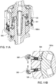
- Receiver assembly 110 may be coupled to tool adapter 150 in order to transfer torque and/or load between the top drive and the tool. Coupling may proceed as a multi-step process. In one embodiment, as illustrated in Figure 7A , coupling begins with inserting central shaft 180 of tool adapter 150 into housing 120 of receiver assembly 110. The tool adapter 150 is oriented so that splines 275 will align with mating features 235 of ring couplers 130 (shown in Figure 7B ) and with mating features 125 of housing 120 (shown in Figure 7B ). For example, during coupling, the ring coupler mating features 235 and the housing mating features 125 may slide between the splines 275.
- Coupling proceeds in Figure 7B , as one or more stop surfaces 131 of one or more ring couplers 130 engage complementary stop surfaces 171 of profile 170 of central shaft 180. As illustrated, stop surfaces 131 are disposed on an interior of lower ring coupler 130-l. It should be appreciated that other stop surface configurations may be considered to accommodate manufacturing and operational conditions. In some embodiments, position sensors may be used in conjunction with or in lieu of stop surfaces to identify when insertion of central shaft 180 into housing 120 has completed. Likewise, optical guides may be utilized to identify or confirm when insertion of central shaft 180 into housing 120 has completed. Coupling proceeds in Figure 7C as the profile 170 is clamped by ring couplers 130.
- support actuator 140-s may be actuated to drive support ring coupler 130-s to rotate 130-r about central axis 285.
- Rotation 130-r of the support ring coupler 130-s may be less than a full turn, less than 180°, or even less than 30°.
- Ring coupler mating features 235 may thereby rotate around profile 170 to engage splines 275.
- Pressure actuator 140-p may be actuated to drive upper ring coupler 130-u to rotate 130-r about central axis 285.
- pressure actuator 140-p may include worm gears.
- Rotation 130-r of the upper ring coupler 130-u may be less than or more than a full turn.
- Threading 255 and linear rack 265 may thereby drive upper ring coupler 130-u to move translationally 130-t downward relative to housing 120, thereby driving lower ring coupler 130-l to move downwards.
- Profile 170 of central shaft 180 may thus be clamped by lower ring coupler 130-l and support ring coupler 130-s.
- Mating features 125 of housing 120 may mesh with and engage splines 275. Torque and/or load may thereby be transferred between the top drive and the tool.
- pressure actuator 140-p may be actuated to drive upper ring coupler 130-u to rotate 130-r about central axis 285, and thereby to drive lower ring coupler 130-l to move translationally 130-t in order to preload the tool stem 160.
- Figure 8 provides another example of receiver assembly 110 coupling to tool adapter 150 in order to transfer torque and/or load between the top drive and the tool.
- coupling begins with inserting central shaft 180 of tool adapter 150 into housing 120 of receiver assembly 110.
- the tool adapter 150 is oriented so that splines 275 will align with mating features 235 of ring couplers 130 (shown in Figures 4B and 8B ) and with mating features 125 of housing 120 (shown in Figures 4D and 8A ).
- the ring coupler mating features 235 and the housing mating features 125 may slide between the splines 275 (e.g ., load splines 275-a, torque splines 275-b).
- Coupling proceeds in Figure 8B , as one or more stop surfaces 121 of housing 120 engage complementary stop surfaces 171 of profile 170 of central shaft 180.
- stop surface configurations may be considered to accommodate manufacturing and/or operational conditions.
- position sensors may be used in conjunction with or in lieu of stop surfaces to identify when insertion of central shaft 180 into housing 120 has completed.
- optical guides may be utilized to identify or confirm when insertion of central shaft 180 into housing 120 has completed.
- Coupling proceeds in Figure 8C as the profile 170 is engaged by ring couplers 130.
- support actuators 140-s may be actuated to drive support ring coupler 130-s to rotate 130-r about central axis 285.
- Ring coupler mating features 235 may thereby rotate around profile 170 to engage load splines 275-a.
- the weight of tool string 2 may not yet be transferred to tool adapter 150.
- Engagement of ring coupler mating features 235 with load splines 275-a may include being disposed in close proximity and/or making at least partial contact.
- Mating features 125 of housing 120 may then mesh with and/or engage torque splines 275-b. Torque and/or load may thereby be transferred between the top drive and the tool.
- receiver assembly 110 may include a clamp 135 and clamp actuator 145.
- clamp 135 may be an annular clamp
- clamp actuator 145 may be a hydraulic cylinder.
- Clamp 135 may move translationally 135-t relative to the housing 120.
- Clamp actuator 145 may drive clamp 135 to move translationally 135-t downward relative to housing 120.
- Load splines 275-a of profile 170 may thus be clamped by clamp 135 and support ring coupler 130-s.
- clamp actuator 145 may be actuated to drive clamp 135 to move translationally 135-t in order to preload the tool stem 160.
- tool coupler 100 may provide length compensation for longitudinal positioning of tool stem 160. It may be beneficial to adjust the longitudinal position of tool stem 160, for example, to provide for threading of piping on tool string 2. Such length compensation may benefit from greater control of longitudinal positioning, motion, and/or torque than is typically available during drilling or completion operations. As illustrated in Figure 9 , a compensation ring coupler 130-c may be configured to provide length compensation of tool stem 160 after load coupling of tool adapter 150 and receiver assembly 110.
- compensation ring coupler 130-c may rotate 130-r about central axis 285 to engage profile 170 of central shaft 180.
- compensation ring coupler 130-c may rotate 130-r to engage compensation splines 275-c with ring coupler mating features 235-c.
- the weight of tool string 2 may not yet be transferred to tool adapter 150.
- Engagement of ring coupler mating features 235-c with compensation splines 275-c may include being disposed in close proximity and/or making at least partial contact.
- compensation ring coupler 130-c may be rotationally fixed to support ring coupler 130-s, so that support actuators 140-s may be actuated to drive support ring coupler 130-s and compensation ring coupler 130-c to simultaneously rotate 130-r about central axis 285.
- compensation ring coupler 130-c may move translationally 135-t relative to the housing 120.
- compensation actuators 140-c may drive compensation ring coupler 130-c to move translationally 135-t relative to housing 120. More specifically, compensation actuators 140-c may drive compensation ring coupler 130-c to move translationally 135-t downward relative to housing 120, and thereby load splines 275-a of profile 170 may be clamped by compensation ring coupler 130-c and support ring coupler 130-s.
- compensation actuators 140-c may be actuated to apply vertical force on compensation ring coupler 130-c.
- compensation actuators 140-c may be one or more hydraulic cylinders.
- Actuation of the upper compensation actuator 140-c may apply a downward force and/or drive compensation ring coupler 130-c to move translationally 130-t downwards relative to housing 120 and/or support ring coupler 130-s, and thereby preload the tool stem 160.
- compensation ring coupler 130-c moves downwards, mating features 235-c may push downwards on load splines 275-a.
- Actuation of the lower compensation actuator 140-c may apply an upward force and/or drive compensation ring coupler 130-c to move translationally 130-t upwards relative to housing 120 and/or support ring coupler 130-s, and thereby provide length compensation for tool stem 160.
- compensation actuators 140-c may thereby cause compensation ring coupler 130-c to move translationally 130-t relative to housing 120 and/or support ring coupler 130-s.
- Housing 120 may have a cavity 315 to allow compensation ring coupler 130-c to move translationally 130-t.
- compensation ring coupler 130-c may move translationally 130-t several hundred millimeters, for example, 120 mm.
- a compensation actuator may be functionally connected to support ring coupler 130-s to provide an upward force in addition to or in lieu of a compensation actuator 140-c applying an upward force on compensation ring coupler 130-c.
- One or more sensors may be used to monitor relative positions of the components of the tool coupler 100.
- sensors may be used to identify or confirm relative alignment or orientation of receiver assembly 110 and tool adapter 150.
- a detector 311 e.g., a magnetic field detector
- a marker 351 e.g., a magnet
- tool adapter 150 may be rotated relative to receiver assembly 110 until the detector 311 detects marker 351, thereby confirming appropriate orientation. It should be appreciated that a variety of orienting sensor types may be considered to accommodate manufacturing and operational conditions.
- sensors may monitor the position of the ring couplers 130 relative to other components of the tool coupler 100.
- external indicators 323 may monitor and/or provide indication of the orientation of support ring coupler 130-s.
- the illustrated embodiment shows rocker pins 323 positioned externally to housing 120.
- the rocker pins 323 are configured to engage with one or more indentions 324 on support ring coupler 130-s. By appropriately locating the indentions 324 and the rocker pins 323, the orientation of support ring coupler 130-s relative to housing 120 may be visually determined.
- Such an embodiment may provide specific indication regarding whether support ring coupler 130-s is oriented appropriately for receiving the load of the tool string 2 (i.e., whether the ring coupler mating features 235 are oriented to engage the load splines 275-a).
- the load of the tool string 2 may be supported until, at least, the ring coupler mating features 235 on the support ring coupler 130-s have engaged the splines 275/275-a.
- a spider may longitudinally supporting the tool string 2 from the rig floor 3f until the ring coupler mating features 235 on the support ring coupler 130-s have engaged the splines 275/275-a.
- the load of the tool string 2 may be supported prior to disengagement of the mating features 235 on the support ring coupler 130-s with the splines 275/275-a.
- the relative sizes of the various components of tool coupler 100 may be selected for coupling/decoupling efficiency, load transfer efficiency, and/or torque transfer efficiency.
- a clearance of 20 mm may be provided in all directions between the top of load splines 275-a and the bottom of housing mating features 125.
- Such relative sizing may allow for more efficient coupling in the event of initial translational misalignment between the tool adapter 150 and the receiver assembly 110.
- the main body of torque splines 275-b and housing mating features 125 may only have a clearance on the order of 1 mm in all directions ( e.g., as illustrated in Figure 8C ).
- guide elements may assist in aligning and/or orienting tool adapter 150 during coupling with receiver assembly 110.
- one or more chamfer may be disposed at a lower-interior location on housing 120.
- One or more ridges and/or grooves may be disposed on central stem 190 to mesh with complementary grooves and/or ridges on central shaft 180.
- One or more pins may be disposed on tool adapter 150 to stab into holes on housing 120 to confirm and/or lock the orientation of the tool adapter 150 with the receiver assembly 110. In some embodiments, such pins/holes may provide stop surfaces to confirm complete insertion of tool adapter 150 into receiver assembly 110.
- seals such as O-rings, may be disposed on central stem 190.
- the seals may be configured to be engaged only when the tool adapter 150 is fully aligned with the receiver assembly 110.
- a locking mechanism may be used that remains locked while the tool coupler 100 conveys axial load. Decoupling may only occur when tool coupler 100 is not carrying load.
- actuators 140 may be self-locking (e.g., electronic interlock or hydraulic interlock).
- a locking pin may be used.
- tool coupler 100 a variety of configurations, sensors, actuators, and/or adapters types and/or configurations may be considered to accommodate manufacturing and operational conditions.
- Possible actuators include, for example, worm drives, hydraulic cylinders, compensation cylinders, etc.
- the actuators may be hydraulically, pneumatically, electrically, and/or manually controlled.
- multiple control mechanism may be utilized to provide redundancy.
- One or more sensors may be used to monitor relative positions of the components of the top drive system.
- the sensors may be position sensors, rotation sensors, pressure sensors, optical sensors, magnetic sensors, etc.
- stop surfaces may be used in conjunction with or in lieu of sensors to identify when components are appropriately positioned and/or oriented.
- optical guides may be utilized to identify or confirm when components are appropriately positioned and/or oriented.
- guide elements e.g., pins and holes, chamfers, etc.
- Bearings and seals may be disposed between components to provide support, cushioning, rotational freedom, and/or fluid management.
- a tool coupler includes a first component comprising: a ring coupler having mating features and rotatable between a first position and a second position; an actuator functionally connected to the ring coupler to rotate the ring coupler between the first position and the second position; and a second component comprising a profile complementary to the ring coupler.
- the mating features do not engage the profile; and with the ring coupler in the second position, the mating features engage the profile to couple the first component to the second component.
- the first component comprises a housing
- the second component comprises a central shaft
- the profile is disposed on an outside of the central shaft.
- the first component comprises a central shaft
- the second component comprises a housing
- the profile is disposed on an inside of the housing.
- the first component is a receiver assembly and the second component is a tool adapter.
- a rotation of the ring coupler is around a central axis of the tool coupler.
- the ring coupler is a single component forming a complete ring.
- the actuator is fixedly connected to the housing.
- the ring coupler is configured to rotate relative to the housing, to move translationally relative to the housing, or to both rotate and move translationally relative to the housing.
- the actuator is functionally connected to the ring coupler to cause the ring coupler to rotate relative to the housing, to move translationally relative to the housing, or to both rotate and move translationally relative to the housing.
- the first component further comprises a central stem having an outer diameter less than an inner diameter of the central shaft.
- the central stem and the central shaft share a central bore.
- the housing includes mating features disposed on an interior of the housing and complementary to the profile.
- the profile and the housing mating features are configured to transfer torque between the first component and the second component.
- the housing mating features are interleaved with features of the profile.
- the profile includes convex features on an outside of the central shaft.
- the profile comprises a plurality of splines that run vertically along an outside of the central shaft.
- the splines are distributed symmetrically about a central axis of the central shaft.
- each of the splines have a same width.
- the profile comprises at least two discontiguous sets of splines distributed vertically along the outside of the central shaft.
- the mating features comprise a plurality of mating features that run vertically along an interior thereof.
- the mating features include convex features on an inner surface of the ring coupler.
- the mating features are distributed symmetrically about a central axis of the ring coupler.
- each of the mating features are the same width.
- the ring coupler comprises cogs distributed on an outside thereof.
- the actuator has gearing that meshes with the cogs.
- the actuator comprises at least one of a worm drive and a hydraulic cylinder.
- the housing has a linear rack on an interior thereof; the ring coupler has threading on an outside thereof; and the ring coupler and the linear rack are configured such that rotation of the ring coupler causes the ring coupler to move translationally relative to the housing.
- the first component further comprises a second ring coupler; the actuator is configured to drive the ring coupler to rotate about a central axis; and the ring coupler is configured to drive the second ring coupler to move translationally relative to the housing.
- the first component further comprises a second actuator and a second ring coupler.
- the second actuator is functionally connected to the second ring coupler.
- the second actuator is functionally connected to the ring coupler.
- the first component further comprises a wedge bushing below the ring coupler.
- the first component further comprises an external indicator indicative of an orientation of the ring coupler.
- the first component further comprises a second ring coupler and a second actuator; and the second actuator is functionally connected to the second ring coupler to cause the second ring coupler to move translationally relative to the ring coupler.
- the second ring coupler is rotationally fixed to the ring coupler.
- the profile comprises a first set of splines and a second set of splines, each distributed vertically along the outside of the central shaft; and the first set of splines is discontiguous with the second set of splines.
- the ring coupler includes mating features on an interior thereof that are complementary with the first set of splines; and the second ring coupler includes mating features on an interior thereof that are complementary with the second set of splines.
- the first set of splines is between the ring coupler and the second ring coupler.
- the second ring coupler is capable of pushing downwards on the first set of splines; and the second ring coupler is capable of pushing upwards on the second set of splines.
- the second actuator comprises an upwards actuator that is capable of applying an upwards force on the second ring coupler, and a downwards actuator that is capable of applying a downwards force on the second ring coupler.
- the actuator comprises an upwards actuator that is capable of applying an upwards force on the ring coupler
- the second actuator comprises a downwards actuator that is capable of applying a downwards force on the second ring coupler
- a method of coupling a first component to a second component includes inserting a central shaft of the first component into a housing of the second component; rotating a ring coupler around the central shaft; and engaging mating features of the ring coupler with a profile, wherein the profile is on an outside of the central shaft or an inside of the housing.
- the first component is a tool adapter and the second component is a receiver assembly.
- the method also includes, after engaging the mating features, longitudinally positioning a tool stem connected to the central shaft.
- the method also includes detecting when inserting the central shaft into the housing has completed.
- the profile comprises a plurality of splines distributed on an outside of the central shaft.
- the method also includes sliding the ring coupler mating features between the splines.
- the method also includes sliding a plurality of housing mating features between the splines.
- the method also includes, prior to inserting the central shaft, detecting an orientation of the splines relative to mating features of the housing.
- an actuator drives the ring coupler to rotate about a central axis of the ring coupler.
- rotating the ring coupler comprises rotation of less than a full turn.
- the method also includes, after engaging the mating features with the profile, transferring at least one of torque and load between the first component and the second component.
- the profile comprises an upper set and a lower set of splines distributed vertically along the outside of the central shaft; and the ring coupler rotates between the two sets of splines.
- the method also includes interleaving the lower set of splines with a plurality of housing mating features.
- the method also includes, after engaging the ring coupler mating features with the profile: transferring torque between the lower set of splines and the housing mating features, and transferring load between the upper set of splines and the ring coupler mating features.
- a method of coupling a first component to a second component includes inserting a central shaft of the first component into a housing of the second component; rotating a first ring coupler around the central shaft; and clamping a profile using the first ring coupler and a second ring coupler, wherein the profile is on an outside of the central shaft or an inside of the housing.
- the first component is a tool adapter and the second component is a receiver assembly.
- the method also includes, after rotating the first ring coupler, rotating a third ring coupler around the central shaft, wherein: rotating the first ring coupler comprises rotation of less than a full turn, and rotating the third ring coupler comprise rotation of more than a full turn.
- rotating the first ring coupler causes rotation of the second ring coupler.
- the method also includes, after rotating the first ring coupler, moving the second ring coupler translationally relative to the housing.
- the method also includes, after rotating the first ring coupler: rotating a third ring coupler around the central shaft; and moving the second ring coupler and the third ring coupler translationally relative to the housing.
- the method also includes, after clamping the profile, transferring at least one of torque and load between the first component and the second component.
- a method of coupling a first component to a second component includes inserting a central shaft of the first component into a housing of the second component; rotating a first ring coupler around the central shaft; and moving a second ring coupler vertically relative to the housing to engage a profile, wherein the profile is on an outside of the central shaft or an inside of the housing.
- the first component is a tool adapter and the second component is a receiver assembly.
- engaging the profile comprises at least one of: clamping first splines of the profile between the first ring coupler and the second ring coupler; and pushing upwards on second splines of the profile.
- engaging the profile comprises both, at different times: pushing downward on first splines of the profile; and pushing upwards on second splines of the profile.
- the method also includes supporting a load from the first splines of the profile with the first ring coupler.
Abstract
Description
- Embodiments of the present invention generally relate to equipment and methods for coupling a top drive to one or more tools. The coupling may transfer both axial load and torque bi-directionally from the top drive to the one or more tools.
- A wellbore is formed to access hydrocarbon-bearing formations (e.g., crude oil and/or natural gas) or for geothermal power generation by the use of drilling. Drilling is accomplished by utilizing a drill bit that is mounted on the end of a tool string. To drill within the wellbore to a predetermined depth, the tool string is often rotated by a top drive on a drilling rig. After drilling to a predetermined depth, the tool string and drill bit are removed, and a string of casing is lowered into the wellbore. Well construction and completion operations may then be conducted.
- During drilling and well construction/completion, various tools are used which have to be attached to the top drive. The process of changing tools is very time consuming and dangerous, requiring personnel to work at heights. The attachments between the tools and the top drive typically include mechanical, electrical, optical, hydraulic, and/or pneumatic connections, conveying torque, load, data, signals, and/or power.
- Typically, sections of a tool string are connected together with threaded connections. Such threaded connections are capable of transferring load. Right-hand (RH) threaded connections are also capable of transferring RH torque. However, application of left-hand (LH) torque to a tool string with RH threaded connections (and vice versa) risks breaking the string. Methods have been employed to obtain bi-directional torque holding capabilities for connections. Some examples of these bi-directional setting devices include thread locking mechanisms for saver subs, hydraulic locking rings, set screws, jam nuts, lock washers, keys, cross/thru-bolting, lock wires, clutches and thread locking compounds. However, these solutions have shortcomings. For example, many of the methods used to obtain bi-directional torque capabilities are limited by friction between component surfaces or compounds that typically result in a relative low torque resistant connection. Locking rings may provide only limited torque resistance, and it may be difficult to fully monitor any problem due to limited accessibility and location. For applications that require high bi-directional torque capabilities, only positive locking methods such as keys, clutches or cross/through-bolting are typically effective. Further, some high bi-directional torque connections require both turning and milling operations to manufacture, which increase the cost of the connection over just a turning operation required to manufacture a simple male-to-female threaded connection. Some high bi-directional torque connections also require significant additional components as compared to a simple male-to-female threaded connection, which adds to the cost.
- Threaded connections also suffer from the risk of cross threading. When the threads are not correctly aligned before torque is applied, cross threading may damage the components. The result may be a weak or unsealed connection, risk of being unable to separate the components, and risk of being unable to re-connect the components once separated. Therefore, threading (length) compensation systems may be used to provide accurate alignment and/or positioning of components having threaded connections prior to application of make-up (or break-out) torque. Conventional threading compensation systems may require unacceptable increase in component length. For example, if a hydraulic cylinder positions a threaded component, providing threading compensation with the cylinder first requires an increase in the cylinder stroke length equal to the length compensation path. Next, the cylinder housing must also be increased by the same amount to accommodate the cylinder stroke in a retracted position. So adding conventional threading compensation to a hydraulic cylinder would require additional component space up to twice the length compensation path length. For existing rigs, where vertical clearance and component weight are important, this can cause problems.
- Safer, faster, more reliable, and more efficient connections that are capable of conveying load, data, signals, power and/or bi-directional torque between the tool string and the top drive are needed.
- The present invention generally relates to equipment and methods for coupling a top drive to one or more tools. The coupling may transfer both axial load and torque bi-directionally from the top drive to the one or more tools.
- In an embodiment, a tool coupler includes a first component comprising: a ring coupler having mating features and rotatable between a first position and a second position; an actuator functionally connected to the ring coupler to rotate the ring coupler between the first position and the second position; and a second component comprising a profile complementary to the ring coupler.
- In an embodiment, a method of coupling a first component to a second component includes inserting a central shaft of the first component into a housing of the second component; rotating a ring coupler around the central shaft; and engaging mating features of the ring coupler with a profile, wherein the profile is on an outside of the central shaft or an inside of the housing.
- In an embodiment, a method of coupling a first component to a second component includes inserting a central shaft of the first component into a housing of the second component; rotating a first ring coupler around the central shaft; and clamping a profile using the first ring coupler and a second ring coupler, wherein the profile is on an outside of the central shaft or an inside of the housing.
- In an embodiment, a method of coupling a first component to a second component includes inserting a central shaft of the first component into a housing of the second component; rotating a first ring coupler around the central shaft; and moving a second ring coupler vertically relative to the housing to engage a profile, wherein the profile is on an outside of the central shaft or an inside of the housing.
- So that the manner in which the above recited features of the present invention can be understood in detail, a more particular description of the invention, briefly summarized above, may be had by reference to embodiments, some of which are illustrated in the appended drawings. It is to be noted, however, that the appended drawings illustrate only typical embodiments of this invention and are therefore not to be considered limiting of its scope, for the invention may admit to other equally effective embodiments.
-
Figure 1 illustrates a drilling system, according to embodiments of the present disclosure. -
Figures 2A-2B illustrate an example tool coupler for a top drive system according to embodiments described herein. -
Figures 3A-3C illustrate example central shaft profiles for the tool coupler ofFigures 2A-2B . -
Figures 4A-4D illustrate example ring couplers for the tool coupler ofFigures 2A-2B . -
Figures 5A-5B illustrate example actuators for the tool coupler ofFigures 2A-2B . -
Figures 6A-6C illustrate example ring couplers for the tool coupler ofFigures 2A-2B . -
Figures 7A-7C illustrate a multi-step process for coupling a receiver assembly to a tool adapter. -
Figures 8A-8C illustrate another example tool coupler for a top drive system according to embodiments described herein. -
Figures 9A-9B illustrate example ring couplers for the tool coupler ofFigures 8A-8C . -
Figures 10A-10B illustrate example sensors for the tool coupler ofFigures 8A-8C . -
Figures 11A-11B illustrate other example sensors for the tool coupler ofFigures 8A-8C . -
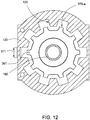
Figure 12 illustrates example components for the tool coupler ofFigures 8A-8C . - The present invention provides equipment and methods for coupling a top drive to one or more tools. The top drive may include a control unit, a drive unit, and a tool coupler. The coupling may transfer torque bi-directionally from the top drive through the tool coupler to the one or more tools. The coupling may provide mechanical, electrical, optical, hydraulic, and/or pneumatic connections. The coupling may conveying torque, load, data, signals, and/or power. For example, axial loads of tool strings may be expected to be several hundred tons, up to, including, and sometimes surpassing 750 tons. Required torque transmission may be tens of thousands of foot-pounds, up to, including, and sometimes surpassing 100 thousand foot-pounds. Embodiments disclosed herein may provide axial connection integrity, capable to support high axial loads, good sealability, resistance to bending, high flow rates, and high flow pressures.
- Some of the many benefits provided by embodiments of this disclosure include a tool coupler having a simple mechanism that is low maintenance. Benefits also include a reliable method to transfer full bi-directional torque, thereby reducing the risk of accidental breakout of threaded connections along the tool string. In some embodiments, the moving parts of the mechanism may be completely covered. During coupling or decoupling, no turning of exposed parts of the coupler or tool may be required. Coupling and decoupling is not complicated, and the connections may be release by hand as a redundant backup. Embodiments of this disclosure may also provide a fast, hands-free method to connect and transfer power from the top drive to the tools. Embodiments may also provide automatic connection for power and data communications. Embodiments may also provide threading (length) compensation to reduce impact, forces, and/or damage at the threads. Embodiments may provide confirmation of orientation and/or position of the components, for example a stab-in signal. During make-up or break-out, threading compensation may reduce the axial load at the thread and therefore the risk of damage of the thread.
-
Figure 1 illustrates adrilling system 1, according to embodiments of the present disclosure. Thedrilling system 1 may include adrilling rig derrick 3d on adrilling rig floor 3f. As illustrated,drilling rig floor 3f is at the surface of asubsurface formation 7, but thedrilling system 1 may also be an offshore drilling unit, having a platform or subsea wellhead in place of or in addition torig floor 3f. The derrick may support a hoist 5, thereby supporting atop drive 4. In some embodiments, the hoist 5 may be connected to thetop drive 4 by threaded couplings. Thetop drive 4 may be connected to atool string 2. At various times,top drive 4 may support the axial load oftool string 2. In some embodiments, thetop drive 4 may be connected to thetool string 2 by threaded couplings. Therig floor 3f may have an opening through which thetool string 2 extends downwardly into awellbore 9. At various times,rig floor 3f may support the axial load oftool string 2. During operation,top drive 4 may provide torque totool string 2, for example to operate a drilling bit near the bottom of thewellbore 9. Thetool string 2 may include joints of drill pipe connected together, such as by threaded couplings. - At various times,
top drive 4 may provide right hand (RH) torque or left hand (LH) torque totool string 2, for example to make up or break out joints of drill pipe. Power and/or signals may be communicated betweentop drive 4 andtool string 2. For example, pneumatic, hydraulic, electrical, optical, or other power and/or signals may be communicated betweentop drive 4 andtool string 2. Thetop drive 4 may include a control unit, a drive unit, and a tool coupler. In some embodiments, the tool coupler may utilize threaded connections. In some embodiments, the tool coupler may be a combined multi-coupler (CMC) or quick connector to support load and transfer torque with couplings to transfer power (hydraulic, electric, data, and/or pneumatic). -
Figure 2A illustrates atool coupler 100 for a top drive system (e.g.,top drive 4 inFigure 1 ) according to embodiments described herein. Generally,tool coupler 100 includes areceiver assembly 110 and atool adapter 150. Thereceiver assembly 110 generally includes ahousing 120, one ormore ring couplers 130, and one ormore actuators 140 functionally connected to thering couplers 130. Optionally, eachring coupler 130 may be a single component forming a complete ring, multiple components connected together to form a complete ring, a single component forming a partial ring, or multiple components connected together to form one or more partial rings. Thehousing 120 may be connected to a top drive (e.g.,top drive 4 inFigure 1 ). Theactuators 140 may be fixedly connected to thehousing 120. In some embodiments, theactuators 140 may be connected with bearings (e.g., a spherical bearing connecting theactuator 140 to the housing, and another spherical bearing connecting theactuator 140 to thering coupler 130. Thering couplers 130 may be connected to thehousing 120 such that thering couplers 130 may rotate 130-r relative to thehousing 120. Thering couplers 130 may be connected to thehousing 120 such that thering couplers 130 may move translationally 130-t (e.g., up or down) relative to thehousing 120. Thetool adapter 150 generally includes atool stem 160, aprofile 170 that is complementary to thering couplers 130 of thereceiver assembly 110, and acentral shaft 180. The tool stem 160 generally remains below thereceiver assembly 110. The tool stem 160 connects thetool coupler 100 to thetool string 2. Thecentral shaft 180 generally inserts into thehousing 120 of thereceiver assembly 110. Thehousing 120 may include acentral stem 190 with an outer diameter less than or equal to an inner diameter ofcentral shaft 180. Thecentral stem 190 andcentral shaft 180 may share a central bore 165 (e.g. providing fluid communication through the tool coupler 100). In some embodiments,central bore 165 is a sealed mud channel. In some embodiments,central bore 165 provides a fluid connection (e.g., a high pressure fluid connection). Theprofile 170 may be disposed on the outside of thecentral shaft 180. Theprofile 170 may include convex features on the outer surface ofcentral shaft 180. Thehousing 120 may have mating features 125 that are complementary toprofile 170. The housing mating features 125 may be disposed on an interior of thehousing 120. The housing mating features 125 may include convex features on an inner surface of thehousing 120. When thereceiver assembly 110 is coupled to thetool adapter 150, housing mating features 125 may be interleaved with features ofprofile 170 aroundcentral shaft 180. During coupling or decoupling operations, theactuators 140 may cause thering couplers 130 to rotate 130-r around thecentral shaft 180, and/or theactuators 140 may cause thering couplers 130 to move translationally 130-t relative tocentral shaft 180. Rotation 130-r of thering coupler 130 may be less than a full turn, less than 180 °, or even less than 30°. When thereceiver assembly 110 is coupled to thetool adapter 150,tool coupler 100 may transfer torque and/or load between the top drive and the tool. - It should be understood that the components of tool couplers described herein could be usefully implemented in reverse configurations. For example,
Figure 2B illustrates a tool coupler 100' having a reverse configuration of components as illustrated inFigure 2A . Generally, tool coupler 100' includes a receiver assembly 110' and a tool adapter 150'. The tool adapter 150' generally includes a housing 120', one or more ring couplers 130', and one or more actuators 140' functionally connected to the ring couplers 130'. The housing 120' may be connected to thetool string 2. The actuators 140' may be fixedly connected to the housing 120'. The ring couplers 130' may be connected to the housing 120' such that the ring couplers 130' may rotate and/or move translationally relative to the housing 120'. The receiver assembly 110' generally includes a drive stem 160', a profile 170' that is complementary to the ring couplers 130' of the tool adapter 150', and a central shaft 180'. The drive stem 160' generally remains above the tool adapter 150'. The drive stem 160' connects thetool coupler 100 to a top drive (e.g.,top drive 4 inFigure 1 ). The central shaft 180' generally inserts into the housing 120' of the tool adapter 150'. The housing 120' may include a central stem 190' with an outer diameter less than or equal to an inner diameter of central shaft 180'. The central stem 190' and central shaft 180' may share a central bore 165' (e.g. providing fluid communication through the tool coupler 100'). The profile 170' may be disposed on the outside of the central shaft 180'. The profile 170' may include convex features on the outer surface of central shaft 180'. The housing 120' may have mating features 125' that are complementary to profile 170'. The housing mating features 125' may be disposed on an interior of the housing 120'. The housing mating features 125' may include convex features on an inner surface of the housing 120'. During coupling or decoupling operations, the actuators 140' may cause the ring couplers 130' to rotate and/or to move translationally relative to central shaft 180'. When the receiver assembly 110' is coupled to the tool adapter 150', tool coupler 100' may transfer torque and/or load between the top drive and the tool. Consequently, for each embodiment described herein, it should be understood that the components of the tool couplers could be usefully implemented in reverse configurations. - As illustrated in
Figure 3 , theprofile 170 may includesplines 275 distributed on the outside ofcentral shaft 180. Thesplines 275 may run vertically alongcentral shaft 180. (It should be understood that "vertically", "up", and "down" as used herein refer to the general orientation oftop drive 4 as illustrated inFigure 1 . In some instances, the orientation may vary somewhat, in response to various operational conditions. In any instance wherein the central axis of the tool coupler is not aligned precisely with the direction of gravitational force, "vertically", "up", and "down" should be understood to be along the central axis of the tool coupler.) Thesplines 275 may (as shown) or may not (not shown) be distributed symmetrically about thecentral axis 185 of thecentral shaft 180. The width of eachspline 275 may (as shown) or may not (not shown) match the width of theother splines 275. Thesplines 275 may run contiguously along the outside of central shaft 180 (as shown inFigure 3A ). Thesplines 275 may include two or more discontiguous sets of splines distributed vertically along the outside of central shaft 180 (e.g., splines 275-a and 275-b inFigure 3B ; splines 275-a, 275-b, and 275-c inFigure 3C ).Figure 3A illustrates sixsplines 275 distributed about thecentral axis 185 of thecentral shaft 180.Figures 3B and3C illustrate tensplines 275 distributed about thecentral axis 185 of thecentral shaft 180. It should be appreciated that any number of splines may be considered to accommodate manufacturing and operational conditions.Figure 3C also illustrates astop surface 171 to be discussed below. - As illustrated in
Figure 4 , one or more of thering couplers 130 may have mating features 235 on an interior thereof. The ring coupler mating features 235 may include convex features on an inner surface of thering coupler 130. Thering coupler 130 may havecogs 245 distributed on an outside thereof (further discussed below). In some embodiments, thecogs 245 may be near the top of the ring coupler 130 (not shown). The mating features 235 may be complementary withsplines 275 from the respectivecentral shaft 180. For example, during coupling or decoupling ofreceiver assembly 110 andtool adapter 150, the mating features 235 may slide between thesplines 275. The mating features 235 may run vertically along the interior ofring coupler 130. The mating features 235 may (as shown) or may not (not shown) be distributed symmetrically about thecentral axis 285 of thering coupler 130. The width of eachmating feature 235 may (as shown) or may not (not shown) match the width of the other mating features 235. The mating features 235 may run contiguously along the interior of the ring couplers 130 (as shown inFigures 4A and 4B ). The mating features 235 may include two or more discontiguous sets of mating features distributed vertically along the interior of thering couplers 130. For example, as shown inFigure 4C , ring coupler 130-c includes mating features 235-c, while ring coupler 130-s includes mating features 235-s which are below mating features 235-c. In some embodiments, such discontiguous sets of mating features may be rotationally coupled. In the illustrated embodiment, ring coupler 130-c may be fixed to ring coupler 130-s, thereby rotationally coupling mating features 235-c with mating features 235-s.Figure 4A illustrates six mating features 235 distributed about thecentral axis 285 of thering couplers 130.Figures 4B and4C illustrates ten mating features 235 distributed about thecentral axis 285 of thecentral shaft 180. It should be appreciated that any number of mating features may be considered to accommodate manufacturing and operational conditions.Figure 4C also illustrates astop surface 131 to be discussed below. - Likewise, as illustrated in
Figure 4D ,housing 120 may have mating features 125 on an interior thereof. As with the ring coupler mating features 235, the housing mating features 125 may be complementary withsplines 275 from the respectivecentral shaft 180. For example, during coupling or decoupling ofreceiver assembly 110 andtool adapter 150, the mating features 125 may slide between thesplines 275. The mating features 125 may run vertically along the interior ofhousing 120. The housing mating features 125 may be generally located lower on thehousing 120 than the operational position ofring couplers 130. The mating features 125 may (as shown) or may not (not shown) be distributed symmetrically about thecentral axis 385 of thehousing 120. The width of eachmating feature 125 may (as shown) or may not (not shown) match the width of the other mating features 125. The mating features 125 may run contiguously along the interior of the housing 120 (as shown). - As illustrated in
Figure 5 , one ormore actuators 140 may be functionally connected to ringcouplers 130.Figure 5A illustrates an embodiment having threering couplers 130 and twoactuators 140.Figure 5B illustrates an embodiment showing onering coupler 130 and twoactuators 140. It should be appreciated that any number of ring couplers and actuators may be considered to accommodate manufacturing and operational conditions. Theactuators 140 illustrated inFigure 5A are worm drives, and the actuators illustrated inFigure 5B are hydraulic cylinders. Other types ofactuators 140 may be envisioned to drive motion of thering couplers 130 relative to thehousing 120. Adjacent to each actuator 140 inFigure 5A arering couplers 130 havingcogs 245 distributed on an outside thereof (better seen inFigure 4A ). Gearing of theactuators 140 may mesh with thecogs 245. The twoactuators 140 inFigure 5A can thereby independently drive the twoadjacent ring couplers 130 to rotate 130-r aboutcentral axis 285. The twoactuators 140 inFigure 5B (i.e., the hydraulic cylinders) are both connected to thesame ring coupler 130. The hydraulic cylinders are each disposed incavity 115 in thehousing 120 to permit linear actuation by the hydraulic cylinder. The twoactuators 140 inFigure 5B can thereby drive thering coupler 130 to rotate 130-r aboutcentral axis 285. For example,ring coupler 130 shown inFigure 4B includes pin holes 142 positioned and sized to operationally couple to pins 141 (shown inFigure 11A ) ofactuators 140. As illustrated inFigure 5B , linear motion of theactuators 140 may causering coupler 130 to rotate, for example between about 0° and about 18°.Actuators 140 may be hydraulically, electrically, or manually controlled. In some embodiments, multiple control mechanism may be utilized to provide redundancy. - In some embodiments, one or
more ring couplers 130 may move translationally 130-t relative to thehousing 120. For example, as illustrated inFigure 6 , aring coupler 130, such as upper ring coupler 130-u, may have threading 255 on an outside thereof. The threading 255 may mesh with alinear rack 265 on an interior ofhousing 120. As upper ring coupler 130-u rotates 130-r aboutcentral axis 285, threading 255 andlinear rack 265 drive upper ring coupler 130-u to move translationally 130-t relative tohousing 120.Housing 120 may have acavity 215 to allow upper ring coupler 130-u to move translationally 130-t. In the illustrated embodiment, upper ring coupler 130-u is connected to lower ring coupler 130-l such that translational motion is transferred between thering couplers 130. The connection between upper ring coupler 130-u and lower ring coupler 130-l may or may not also transfer rotational motion. In the illustrated embodiment, theactuator 140 may drive upper ring coupler 130-u to rotate 130-r aboutcentral axis 285, thereby driving upper ring coupler 130-u to move translationally 130-t relative tohousing 120, and thereby driving lower ring coupler 130-l to move translationally 130-t relative tohousing 120. - In some embodiments, the lower ring coupler 130-l may be a bushing. In some embodiments, the interior diameter of the lower ring coupler 130-l may be larger at the bottom than at the top.
- In some embodiments, the lower ring coupler may be a wedge bushing, having an interior diameter that linearly increases from top to bottom.
-
Receiver assembly 110 may be coupled totool adapter 150 in order to transfer torque and/or load between the top drive and the tool. Coupling may proceed as a multi-step process. In one embodiment, as illustrated inFigure 7A , coupling begins with insertingcentral shaft 180 oftool adapter 150 intohousing 120 ofreceiver assembly 110. Thetool adapter 150 is oriented so thatsplines 275 will align with mating features 235 of ring couplers 130 (shown inFigure 7B ) and with mating features 125 of housing 120 (shown inFigure 7B ). For example, during coupling, the ring coupler mating features 235 and the housing mating features 125 may slide between thesplines 275. Coupling proceeds inFigure 7B , as one or more stop surfaces 131 of one ormore ring couplers 130 engage complementary stop surfaces 171 ofprofile 170 ofcentral shaft 180. As illustrated, stopsurfaces 131 are disposed on an interior of lower ring coupler 130-l. It should be appreciated that other stop surface configurations may be considered to accommodate manufacturing and operational conditions. In some embodiments, position sensors may be used in conjunction with or in lieu of stop surfaces to identify when insertion ofcentral shaft 180 intohousing 120 has completed. Likewise, optical guides may be utilized to identify or confirm when insertion ofcentral shaft 180 intohousing 120 has completed. Coupling proceeds inFigure 7C as theprofile 170 is clamped byring couplers 130. For example, support actuator 140-s may be actuated to drive support ring coupler 130-s to rotate 130-r aboutcentral axis 285. Rotation 130-r of the support ring coupler 130-s may be less than a full turn, less than 180°, or even less than 30°. Ring coupler mating features 235 may thereby rotate aroundprofile 170 to engagesplines 275. Pressure actuator 140-p may be actuated to drive upper ring coupler 130-u to rotate 130-r aboutcentral axis 285. For example, pressure actuator 140-p may include worm gears. Rotation 130-r of the upper ring coupler 130-u may be less than or more than a full turn.Threading 255 andlinear rack 265 may thereby drive upper ring coupler 130-u to move translationally 130-t downward relative tohousing 120, thereby driving lower ring coupler 130-l to move downwards.Profile 170 ofcentral shaft 180 may thus be clamped by lower ring coupler 130-l and support ring coupler 130-s. Mating features 125 ofhousing 120 may mesh with and engagesplines 275. Torque and/or load may thereby be transferred between the top drive and the tool. - In some embodiments, pressure actuator 140-p may be actuated to drive upper ring coupler 130-u to rotate 130-r about
central axis 285, and thereby to drive lower ring coupler 130-l to move translationally 130-t in order to preload thetool stem 160. -
Figure 8 provides another example ofreceiver assembly 110 coupling totool adapter 150 in order to transfer torque and/or load between the top drive and the tool. In one embodiment, as illustrated inFigure 8A , coupling begins with insertingcentral shaft 180 oftool adapter 150 intohousing 120 ofreceiver assembly 110. Thetool adapter 150 is oriented so thatsplines 275 will align with mating features 235 of ring couplers 130 (shown inFigures 4B and8B ) and with mating features 125 of housing 120 (shown inFigures 4D and8A ). For example, during coupling, the ring coupler mating features 235 and the housing mating features 125 may slide between the splines 275 (e.g., load splines 275-a, torque splines 275-b). Coupling proceeds inFigure 8B , as one or more stop surfaces 121 ofhousing 120 engage complementary stop surfaces 171 ofprofile 170 ofcentral shaft 180. It should be appreciated that other stop surface configurations may be considered to accommodate manufacturing and/or operational conditions. In some embodiments, position sensors may be used in conjunction with or in lieu of stop surfaces to identify when insertion ofcentral shaft 180 intohousing 120 has completed. Likewise, optical guides may be utilized to identify or confirm when insertion ofcentral shaft 180 intohousing 120 has completed. Coupling proceeds inFigure 8C as theprofile 170 is engaged byring couplers 130. For example, support actuators 140-s may be actuated to drive support ring coupler 130-s to rotate 130-r aboutcentral axis 285. Ring coupler mating features 235 may thereby rotate aroundprofile 170 to engage load splines 275-a. It should be understood that, while support ring coupler 130-s is rotating 130-r aboutcentral axis 285, the weight oftool string 2 may not yet be transferred totool adapter 150. Engagement of ring coupler mating features 235 with load splines 275-a may include being disposed in close proximity and/or making at least partial contact. Mating features 125 ofhousing 120 may then mesh with and/or engage torque splines 275-b. Torque and/or load may thereby be transferred between the top drive and the tool. - In some embodiments,
receiver assembly 110 may include aclamp 135 andclamp actuator 145. For example, as illustrated inFigure 8C , clamp 135 may be an annular clamp, and clampactuator 145 may be a hydraulic cylinder.Clamp 135 may move translationally 135-t relative to thehousing 120.Clamp actuator 145 may driveclamp 135 to move translationally 135-t downward relative tohousing 120. Load splines 275-a ofprofile 170 may thus be clamped byclamp 135 and support ring coupler 130-s. In some embodiments,clamp actuator 145 may be actuated to driveclamp 135 to move translationally 135-t in order to preload thetool stem 160. - In some embodiments,
tool coupler 100 may provide length compensation for longitudinal positioning oftool stem 160. It may be beneficial to adjust the longitudinal position oftool stem 160, for example, to provide for threading of piping ontool string 2. Such length compensation may benefit from greater control of longitudinal positioning, motion, and/or torque than is typically available during drilling or completion operations. As illustrated inFigure 9 , a compensation ring coupler 130-c may be configured to provide length compensation of tool stem 160 after load coupling oftool adapter 150 andreceiver assembly 110. - Similar to support ring coupler 130-s, compensation ring coupler 130-c may rotate 130-r about
central axis 285 to engageprofile 170 ofcentral shaft 180. For example, as illustrated inFigure 9A , compensation ring coupler 130-c may rotate 130-r to engage compensation splines 275-c with ring coupler mating features 235-c. It should be understood that, while compensation ring coupler 130-c is rotating 130-r aboutcentral axis 285, the weight oftool string 2 may not yet be transferred totool adapter 150. Engagement of ring coupler mating features 235-c with compensation splines 275-c may include being disposed in close proximity and/or making at least partial contact. In some embodiments, compensation ring coupler 130-c may be rotationally fixed to support ring coupler 130-s, so that support actuators 140-s may be actuated to drive support ring coupler 130-s and compensation ring coupler 130-c to simultaneously rotate 130-r aboutcentral axis 285. - Similar to clamp 135, compensation ring coupler 130-c may move translationally 135-t relative to the
housing 120. For example, as illustrated inFigure 9B , compensation actuators 140-c may drive compensation ring coupler 130-c to move translationally 135-t relative tohousing 120. More specifically, compensation actuators 140-c may drive compensation ring coupler 130-c to move translationally 135-t downward relative tohousing 120, and thereby load splines 275-a ofprofile 170 may be clamped by compensation ring coupler 130-c and support ring coupler 130-s. In some embodiments, compensation actuators 140-c may be actuated to apply vertical force on compensation ring coupler 130-c. In some embodiments, compensation actuators 140-c may be one or more hydraulic cylinders. Actuation of the upper compensation actuator 140-c may apply a downward force and/or drive compensation ring coupler 130-c to move translationally 130-t downwards relative tohousing 120 and/or support ring coupler 130-s, and thereby preload thetool stem 160. When compensation ring coupler 130-c moves downwards, mating features 235-c may push downwards on load splines 275-a. Actuation of the lower compensation actuator 140-c may apply an upward force and/or drive compensation ring coupler 130-c to move translationally 130-t upwards relative tohousing 120 and/or support ring coupler 130-s, and thereby provide length compensation fortool stem 160. When compensation ring coupler 130-c moves upwards, mating features 235-c may push upwards on compensation splines 275-c. Compensation actuators 140-c may thereby cause compensation ring coupler 130-c to move translationally 130-t relative tohousing 120 and/or support ring coupler 130-s.Housing 120 may have acavity 315 to allow compensation ring coupler 130-c to move translationally 130-t. In some embodiments, compensation ring coupler 130-c may move translationally 130-t several hundred millimeters, for example, 120 mm. In some embodiments, a compensation actuator may be functionally connected to support ring coupler 130-s to provide an upward force in addition to or in lieu of a compensation actuator 140-c applying an upward force on compensation ring coupler 130-c. - One or more sensors may be used to monitor relative positions of the components of the
tool coupler 100. For example, as illustrated inFigure 10 , sensors may be used to identify or confirm relative alignment or orientation ofreceiver assembly 110 andtool adapter 150. In an embodiment, a detector 311 (e.g., a magnetic field detector) may be attached toreceiver assembly 110, and a marker 351 (e.g., a magnet) may be attached totool adapter 150. Prior to insertion,tool adapter 150 may be rotated relative toreceiver assembly 110 until thedetector 311 detectsmarker 351, thereby confirming appropriate orientation. It should be appreciated that a variety of orienting sensor types may be considered to accommodate manufacturing and operational conditions. - As another example, sensors may monitor the position of the
ring couplers 130 relative to other components of thetool coupler 100. For example, as illustrated inFigure 11 ,external indicators 323 may monitor and/or provide indication of the orientation of support ring coupler 130-s. The illustrated embodiment shows rocker pins 323 positioned externally tohousing 120. The rocker pins 323 are configured to engage with one ormore indentions 324 on support ring coupler 130-s. By appropriately locating theindentions 324 and the rocker pins 323, the orientation of support ring coupler 130-s relative tohousing 120 may be visually determined. Such an embodiment may provide specific indication regarding whether support ring coupler 130-s is oriented appropriately for receiving the load of the tool string 2 (i.e., whether the ring coupler mating features 235 are oriented to engage the load splines 275-a). The load of thetool string 2 may be supported until, at least, the ring coupler mating features 235 on the support ring coupler 130-s have engaged thesplines 275/275-a. For example, a spider may longitudinally supporting thetool string 2 from therig floor 3f until the ring coupler mating features 235 on the support ring coupler 130-s have engaged thesplines 275/275-a. Likewise, during decoupling, the load of thetool string 2 may be supported prior to disengagement of the mating features 235 on the support ring coupler 130-s with thesplines 275/275-a. - The relative sizes of the various components of
tool coupler 100 may be selected for coupling/decoupling efficiency, load transfer efficiency, and/or torque transfer efficiency. For example, as illustrated inFigure 12 , for ahousing 120 having an outer diameter of between about 36 inches and about 40 inches, a clearance of 20 mm may be provided in all directions between the top of load splines 275-a and the bottom of housing mating features 125. Such relative sizing may allow for more efficient coupling in the event of initial translational misalignment between thetool adapter 150 and thereceiver assembly 110. It should be understood that, once torque coupling is complete, the main body of torque splines 275-b and housing mating features 125 may only have a clearance on the order of 1 mm in all directions (e.g., as illustrated inFigure 8C ). - In some embodiments, guide elements may assist in aligning and/or orienting
tool adapter 150 during coupling withreceiver assembly 110. For example, one or more chamfer may be disposed at a lower-interior location onhousing 120. One or more ridges and/or grooves may be disposed oncentral stem 190 to mesh with complementary grooves and/or ridges oncentral shaft 180. One or more pins may be disposed ontool adapter 150 to stab into holes onhousing 120 to confirm and/or lock the orientation of thetool adapter 150 with thereceiver assembly 110. In some embodiments, such pins/holes may provide stop surfaces to confirm complete insertion oftool adapter 150 intoreceiver assembly 110. - Optionally, seals, such as O-rings, may be disposed on
central stem 190. The seals may be configured to be engaged only when thetool adapter 150 is fully aligned with thereceiver assembly 110. - Optionally, a locking mechanism may be used that remains locked while the
tool coupler 100 conveys axial load. Decoupling may only occur whentool coupler 100 is not carrying load. For example,actuators 140 may be self-locking (e.g., electronic interlock or hydraulic interlock). Alternatively, a locking pin may be used. - It should be appreciated that, for
tool coupler 100, a variety of configurations, sensors, actuators, and/or adapters types and/or configurations may be considered to accommodate manufacturing and operational conditions. For example, although the illustrated embodiments show a configuration wherein the ring couplers are attached to the receiver assembly, reverse configurations are envisioned (e.g., wherein the ring couplers are attached to the tool adapter). Possible actuators include, for example, worm drives, hydraulic cylinders, compensation cylinders, etc. The actuators may be hydraulically, pneumatically, electrically, and/or manually controlled. In some embodiments, multiple control mechanism may be utilized to provide redundancy. One or more sensors may be used to monitor relative positions of the components of the top drive system. The sensors may be position sensors, rotation sensors, pressure sensors, optical sensors, magnetic sensors, etc. In some embodiments, stop surfaces may be used in conjunction with or in lieu of sensors to identify when components are appropriately positioned and/or oriented. Likewise, optical guides may be utilized to identify or confirm when components are appropriately positioned and/or oriented. In some embodiments, guide elements (e.g., pins and holes, chamfers, etc.) may assist in aligning and/or orienting the components oftool coupler 100. Bearings and seals may be disposed between components to provide support, cushioning, rotational freedom, and/or fluid management. - In an embodiment, a tool coupler includes a first component comprising: a ring coupler having mating features and rotatable between a first position and a second position; an actuator functionally connected to the ring coupler to rotate the ring coupler between the first position and the second position; and a second component comprising a profile complementary to the ring coupler.
- In one or more embodiments disclosed herein, with the ring coupler in the first position, the mating features do not engage the profile; and with the ring coupler in the second position, the mating features engage the profile to couple the first component to the second component.
- In one or more embodiments disclosed herein, the first component comprises a housing, the second component comprises a central shaft, and the profile is disposed on an outside of the central shaft.
- In one or more embodiments disclosed herein, the first component comprises a central shaft, the second component comprises a housing, and the profile is disposed on an inside of the housing.
- In one or more embodiments disclosed herein, the first component is a receiver assembly and the second component is a tool adapter.
- In one or more embodiments disclosed herein, a rotation of the ring coupler is around a central axis of the tool coupler.
- In one or more embodiments disclosed herein, the ring coupler is a single component forming a complete ring.
- In one or more embodiments disclosed herein, the actuator is fixedly connected to the housing.
- In one or more embodiments disclosed herein, the ring coupler is configured to rotate relative to the housing, to move translationally relative to the housing, or to both rotate and move translationally relative to the housing.
- In one or more embodiments disclosed herein, the actuator is functionally connected to the ring coupler to cause the ring coupler to rotate relative to the housing, to move translationally relative to the housing, or to both rotate and move translationally relative to the housing.
- In one or more embodiments disclosed herein, the first component further comprises a central stem having an outer diameter less than an inner diameter of the central shaft.
- In one or more embodiments disclosed herein, when the first component is coupled to the second component, the central stem and the central shaft share a central bore.
- In one or more embodiments disclosed herein, the housing includes mating features disposed on an interior of the housing and complementary to the profile.
- In one or more embodiments disclosed herein, the profile and the housing mating features are configured to transfer torque between the first component and the second component.
- In one or more embodiments disclosed herein, when the first component is coupled to the second component, the housing mating features are interleaved with features of the profile.
- In one or more embodiments disclosed herein, the profile includes convex features on an outside of the central shaft.
- In one or more embodiments disclosed herein, the profile comprises a plurality of splines that run vertically along an outside of the central shaft.
- In one or more embodiments disclosed herein, the splines are distributed symmetrically about a central axis of the central shaft.
- In one or more embodiments disclosed herein, each of the splines have a same width.
- In one or more embodiments disclosed herein, the profile comprises at least two discontiguous sets of splines distributed vertically along the outside of the central shaft.
- In one or more embodiments disclosed herein, the mating features comprise a plurality of mating features that run vertically along an interior thereof.
- In one or more embodiments disclosed herein, the mating features include convex features on an inner surface of the ring coupler.
- In one or more embodiments disclosed herein, the mating features are distributed symmetrically about a central axis of the ring coupler.
- In one or more embodiments disclosed herein, each of the mating features are the same width.
- In one or more embodiments disclosed herein, the ring coupler comprises cogs distributed on an outside thereof.
- In one or more embodiments disclosed herein, the actuator has gearing that meshes with the cogs.
- In one or more embodiments disclosed herein, the actuator comprises at least one of a worm drive and a hydraulic cylinder.
- In one or more embodiments disclosed herein, the housing has a linear rack on an interior thereof; the ring coupler has threading on an outside thereof; and the ring coupler and the linear rack are configured such that rotation of the ring coupler causes the ring coupler to move translationally relative to the housing.
- In one or more embodiments disclosed herein, the first component further comprises a second ring coupler; the actuator is configured to drive the ring coupler to rotate about a central axis; and the ring coupler is configured to drive the second ring coupler to move translationally relative to the housing.
- In one or more embodiments disclosed herein, the first component further comprises a second actuator and a second ring coupler.
- In one or more embodiments disclosed herein, the second actuator is functionally connected to the second ring coupler.
- In one or more embodiments disclosed herein, the second actuator is functionally connected to the ring coupler.
- In one or more embodiments disclosed herein, the first component further comprises a wedge bushing below the ring coupler.
- In one or more embodiments disclosed herein, the first component further comprises an external indicator indicative of an orientation of the ring coupler.
- In one or more embodiments disclosed herein, the first component further comprises a second ring coupler and a second actuator; and the second actuator is functionally connected to the second ring coupler to cause the second ring coupler to move translationally relative to the ring coupler.
- In one or more embodiments disclosed herein, the second ring coupler is rotationally fixed to the ring coupler.
- In one or more embodiments disclosed herein, the profile comprises a first set of splines and a second set of splines, each distributed vertically along the outside of the central shaft; and the first set of splines is discontiguous with the second set of splines.
- In one or more embodiments disclosed herein, the ring coupler includes mating features on an interior thereof that are complementary with the first set of splines; and the second ring coupler includes mating features on an interior thereof that are complementary with the second set of splines.
- In one or more embodiments disclosed herein, when the central shaft is inserted into the housing, the first set of splines is between the ring coupler and the second ring coupler.
- In one or more embodiments disclosed herein, the second ring coupler is capable of pushing downwards on the first set of splines; and the second ring coupler is capable of pushing upwards on the second set of splines.
- In one or more embodiments disclosed herein, the second actuator comprises an upwards actuator that is capable of applying an upwards force on the second ring coupler, and a downwards actuator that is capable of applying a downwards force on the second ring coupler.
- In one or more embodiments disclosed herein, the actuator comprises an upwards actuator that is capable of applying an upwards force on the ring coupler, and the second actuator comprises a downwards actuator that is capable of applying a downwards force on the second ring coupler.
- In an embodiment, a method of coupling a first component to a second component includes inserting a central shaft of the first component into a housing of the second component; rotating a ring coupler around the central shaft; and engaging mating features of the ring coupler with a profile, wherein the profile is on an outside of the central shaft or an inside of the housing.
- In one or more embodiments disclosed herein, the first component is a tool adapter and the second component is a receiver assembly.
- In one or more embodiments disclosed herein, the method also includes, after engaging the mating features, longitudinally positioning a tool stem connected to the central shaft.
- In one or more embodiments disclosed herein, the method also includes detecting when inserting the central shaft into the housing has completed.
- In one or more embodiments disclosed herein, the profile comprises a plurality of splines distributed on an outside of the central shaft.
- In one or more embodiments disclosed herein, the method also includes sliding the ring coupler mating features between the splines.
- In one or more embodiments disclosed herein, the method also includes sliding a plurality of housing mating features between the splines.
- In one or more embodiments disclosed herein, the method also includes, prior to inserting the central shaft, detecting an orientation of the splines relative to mating features of the housing.
- In one or more embodiments disclosed herein, an actuator drives the ring coupler to rotate about a central axis of the ring coupler.
- In one or more embodiments disclosed herein, rotating the ring coupler comprises rotation of less than a full turn.
- In one or more embodiments disclosed herein, the method also includes, after engaging the mating features with the profile, transferring at least one of torque and load between the first component and the second component.
- In one or more embodiments disclosed herein, the profile comprises an upper set and a lower set of splines distributed vertically along the outside of the central shaft; and the ring coupler rotates between the two sets of splines.
- In one or more embodiments disclosed herein, the method also includes interleaving the lower set of splines with a plurality of housing mating features.
- In one or more embodiments disclosed herein, the method also includes, after engaging the ring coupler mating features with the profile: transferring torque between the lower set of splines and the housing mating features, and transferring load between the upper set of splines and the ring coupler mating features.
- In an embodiment, a method of coupling a first component to a second component includes inserting a central shaft of the first component into a housing of the second component; rotating a first ring coupler around the central shaft; and clamping a profile using the first ring coupler and a second ring coupler, wherein the profile is on an outside of the central shaft or an inside of the housing.
- In one or more embodiments disclosed herein, the first component is a tool adapter and the second component is a receiver assembly.
- In one or more embodiments disclosed herein, the method also includes, after rotating the first ring coupler, rotating a third ring coupler around the central shaft, wherein: rotating the first ring coupler comprises rotation of less than a full turn, and rotating the third ring coupler comprise rotation of more than a full turn.
- In one or more embodiments disclosed herein, rotating the first ring coupler causes rotation of the second ring coupler.
- In one or more embodiments disclosed herein, the method also includes, after rotating the first ring coupler, moving the second ring coupler translationally relative to the housing.
- In one or more embodiments disclosed herein, the method also includes, after rotating the first ring coupler: rotating a third ring coupler around the central shaft; and moving the second ring coupler and the third ring coupler translationally relative to the housing.
- In one or more embodiments disclosed herein, the method also includes, after clamping the profile, transferring at least one of torque and load between the first component and the second component.
- In an embodiment, a method of coupling a first component to a second component includes inserting a central shaft of the first component into a housing of the second component; rotating a first ring coupler around the central shaft; and moving a second ring coupler vertically relative to the housing to engage a profile, wherein the profile is on an outside of the central shaft or an inside of the housing.
- In one or more embodiments disclosed herein, the first component is a tool adapter and the second component is a receiver assembly.
- In one or more embodiments disclosed herein, engaging the profile comprises at least one of: clamping first splines of the profile between the first ring coupler and the second ring coupler; and pushing upwards on second splines of the profile.
- In one or more embodiments disclosed herein, engaging the profile comprises both, at different times: pushing downward on first splines of the profile; and pushing upwards on second splines of the profile.
- In one or more embodiments disclosed herein, the method also includes supporting a load from the first splines of the profile with the first ring coupler.
- While the foregoing is directed to embodiments of the present invention, other and further embodiments of the invention may be devised without departing from the basic scope thereof, and the scope thereof is determined by the claims that follow.
Claims (15)
- A tool coupler, comprising:a first component having:a ring coupler having mating features and rotatable between a first position and a second position; andan actuator functionally connected to the ring coupler to rotate the ring coupler between the first position and the second position; anda second component having a profile complementary to the ring coupler.
- The tool coupler of claim 1, wherein:when the ring coupler is in the first position, the mating features do not engage the profile; andwhen the ring coupler is in the second position, the mating features engage the profile to couple the first component to the second component.
- The tool coupler of claim 1 or 2, wherein:the first component comprises a housing,the second component comprises a central shaft, andthe profile is disposed on an outside of the central shaft;and/or wherein the first component is a receiver assembly and the second component is a tool adapter.
- The tool coupler of claim 3, wherein:the ring coupler comprises cogs distributed on an outside thereof; andthe actuator has gearing that meshes with the cogs;and/or wherein:the housing has a linear rack on an interior thereof;the ring coupler has threading on an outside thereof; andthe ring coupler and the linear rack are configured such that rotation of the ring coupler causes the ring coupler to move translationally relative to the housing.
- The tool coupler of claim 3 or 4, wherein:the first component further comprises a second ring coupler;the actuator is configured to drive the ring coupler to rotate about a central axis; andthe ring coupler is configured to drive the second ring coupler to move translationally relative to the housing.
- The tool coupler of claim 3, 4 or 5 wherein:the first component further comprises a second ring coupler and a second actuator;the second actuator is functionally connected to the second ring coupler to cause the second ring coupler to move translationally relative to the ring coupler.the profile comprises a first set of splines and a second set of splines, each distributed vertically along the outside of the central shaft; andthe first set of splines is discontiguous with the second set of splines;and/or wherein:the ring coupler includes mating features on an interior thereof that are complementary with the first set of splines; andthe second ring coupler includes mating features on an interior thereof that are complementary with the second set of splines;and/or wherein, when the central shaft is inserted into the housing, the first set of splines is between the ring coupler and the second ring coupler.
- The tool coupler of claim 6, wherein the second actuator comprises an upwards actuator that is capable of applying an upwards force on the second ring coupler, and a downwards actuator that is capable of applying a downwards force on the second ring coupler, and/or wherein the actuator comprises an upwards actuator that is capable of applying an upwards force on the ring coupler, and the second actuator comprises a downwards actuator that is capable of applying a downwards force on the second ring coupler.
- A method of coupling a first component to a second component comprising:inserting a central shaft of the first component into a housing of the second component;rotating a ring coupler around the central shaft; andengaging mating features of the ring coupler with a profile on an outside of the central shaft or an inside of the housing.
- The method of claim 8, further comprising, after engaging the mating features, longitudinally positioning a tool stem connected to the central shaft.
- The method of claim 8 or 9, wherein the profile comprises a plurality of splines distributed on an outside of the central shaft, the method further comprising at least one of:sliding the ring coupler mating features between the splines;sliding a plurality of housing mating features between the splines; andprior to inserting the central shaft, detecting an orientation of the splines relative to mating features of the housing;and/or wherein the method further comprises detecting when inserting the central shaft into the housing has completed.
- The method of claim 8, 9 or 10, wherein:the profile comprises an upper set and a lower set of splines distributed vertically along the outside of the central shaft; andthe ring coupler rotates between the two sets of splines;the method optionally further comprising:interleaving the lower set of splines with a plurality of housing mating features; andafter engaging the ring coupler mating features with the profile:transferring torque between the lower set of splines and the housing mating features, andtransferring load between the upper set of splines and the ring coupler mating features.
- A method of coupling a first component to a second component comprising:inserting a central shaft of the first component into a housing of the second component;rotating a first ring coupler around the central shaft; andclamping a profile using the first ring coupler and a second ring coupler, wherein the profile is on an outside of the central shaft or an inside of the housing.
- The method of claim 12, further comprising, after rotating the first ring coupler, moving the second ring coupler translationally relative to the housing;
and/or, after rotating the first ring coupler, rotating a third ring coupler around the central shaft and moving the second ring coupler and the third ring coupler translationally relative to the housing. - A method of coupling a first component to a second component comprising:inserting a central shaft of the first component into a housing of the second component;rotating a first ring coupler around the central shaft; andmoving a second ring coupler vertically relative to the housing to engage a profile on an outside of the central shaft or an inside of the housing.
- The method of any one of claims 8 to 14, wherein the first component is a tool adapter and the second component is a receiver assembly.
Applications Claiming Priority (1)
| Application Number | Priority Date | Filing Date | Title |
|---|---|---|---|
| US15/445,758 US10954753B2 (en) | 2017-02-28 | 2017-02-28 | Tool coupler with rotating coupling method for top drive |
Publications (2)
| Publication Number | Publication Date |
|---|---|
| EP3366879A1 true EP3366879A1 (en) | 2018-08-29 |
| EP3366879B1 EP3366879B1 (en) | 2020-06-17 |
Family
ID=61256779
Family Applications (1)
| Application Number | Title | Priority Date | Filing Date |
|---|---|---|---|
| EP18158050.7A Active EP3366879B1 (en) | 2017-02-28 | 2018-02-22 | Tool coupler with rotating coupling method for top drive |
Country Status (3)
| Country | Link |
|---|---|
| US (1) | US10954753B2 (en) |
| EP (1) | EP3366879B1 (en) |
| CA (1) | CA2995284C (en) |
Families Citing this family (4)
| Publication number | Priority date | Publication date | Assignee | Title |
|---|---|---|---|---|
| US10745978B2 (en) * | 2017-08-07 | 2020-08-18 | Weatherford Technology Holdings, Llc | Downhole tool coupling system |
| US11148821B2 (en) * | 2019-02-28 | 2021-10-19 | Hamilton Sundstrand Corporation | Motion limiter for ram air turbine (RAT) door linkage |
| US11828125B2 (en) | 2021-04-22 | 2023-11-28 | Onesubsea Ip Uk Limited | Connector assembly for multiple components |
| US11774773B1 (en) * | 2022-10-25 | 2023-10-03 | Ctl Analyzers Llc | Couplers for optical devices for reflected light and fluorescence detection and methods for use |
Citations (5)
| Publication number | Priority date | Publication date | Assignee | Title |
|---|---|---|---|---|
| GB1487948A (en) * | 1974-12-16 | 1977-10-05 | Hunting Oilfield Services Ltd | Pipe connectors |
| US20090151934A1 (en) * | 2007-12-12 | 2009-06-18 | Karsten Heidecke | Top drive system |
| US20120298376A1 (en) * | 2011-05-25 | 2012-11-29 | Twardowski Eric M | Tubular coupling device |
| WO2015176121A1 (en) * | 2014-05-23 | 2015-11-26 | Ignis Technologies Pty Ltd | Bit retaining system |
| US20160215592A1 (en) * | 2015-01-26 | 2016-07-28 | Weatherford Technology Holdings, Llc | Modular top drive system |
Family Cites Families (322)
| Publication number | Priority date | Publication date | Assignee | Title |
|---|---|---|---|---|
| US1367156A (en) | 1920-03-16 | 1921-02-01 | Budd D Mcalvay | Interlocking casing-reducing nipple |
| US1487948A (en) * | 1923-05-25 | 1924-03-25 | Kane Alfred | Radiator-cap light |
| US1610977A (en) | 1924-12-03 | 1926-12-14 | Henry T Scott | Coupling |
| US1822444A (en) | 1930-01-20 | 1931-09-08 | John W Macclatchie | Cementing head |
| US2370354A (en) | 1943-06-07 | 1945-02-27 | George L Hurst | Quick detachable coupling |
| US3147992A (en) | 1961-04-27 | 1964-09-08 | Shell Oil Co | Wellhead connector |
| US3354951A (en) | 1964-02-24 | 1967-11-28 | Offshore Co | Marine drilling apparatus |
| US3385370A (en) | 1966-06-29 | 1968-05-28 | Halliburton Co | Self-fill and flow control safety valve |
| US3747675A (en) | 1968-11-25 | 1973-07-24 | C Brown | Rotary drive connection for casing drilling string |
| US3662842A (en) | 1970-04-14 | 1972-05-16 | Automatic Drilling Mach | Automatic coupling system |
| US3698426A (en) | 1970-07-29 | 1972-10-17 | Smith International | Mud saver valve and method |
| US3766991A (en) | 1971-04-02 | 1973-10-23 | Brown Oil Tools | Electric power swivel and system for use in rotary well drilling |
| US3888318A (en) | 1971-09-16 | 1975-06-10 | Cicero C Brown | Well drilling apparatus |
| US3774697A (en) | 1971-12-09 | 1973-11-27 | C Brown | Rotary drive assembly for handling tubular members |
| US3776320A (en) | 1971-12-23 | 1973-12-04 | C Brown | Rotating drive assembly |
| US3842619A (en) | 1972-08-16 | 1974-10-22 | A Bychurch | Reversible kelly system for rotary drilling |
| US3913687A (en) | 1974-03-04 | 1975-10-21 | Ingersoll Rand Co | Pipe handling system |
| US3915244A (en) | 1974-06-06 | 1975-10-28 | Cicero C Brown | Break out elevators for rotary drive assemblies |
| US3899024A (en) | 1975-01-10 | 1975-08-12 | Production Data Inc | Auxiliary oil well tubing shut-off assembly |
| US3964552A (en) | 1975-01-23 | 1976-06-22 | Brown Oil Tools, Inc. | Drive connector with load compensator |
| US4022284A (en) | 1975-03-17 | 1977-05-10 | Dresser Industries, Inc. | Automatic alignment system for earth boring rig |
| US4051587A (en) | 1976-08-02 | 1977-10-04 | Varco International, Inc. | Pile handling apparatus and methods |
| US4100968A (en) | 1976-08-30 | 1978-07-18 | Charles George Delano | Technique for running casing |
| CA1069494A (en) | 1977-07-21 | 1980-01-08 | Gary D. Gray | Floating cushion sub |
| US4199847A (en) | 1979-01-29 | 1980-04-29 | Armco Inc. | Well riser support having elastomeric bearings |
| US4402239A (en) | 1979-04-30 | 1983-09-06 | Eckel Manufacturing Company, Inc. | Back-up power tongs and method |
| US4235469A (en) | 1979-05-11 | 1980-11-25 | Den-Con Tool Company | Pipe handling apparatus |
| US4374595A (en) | 1980-06-16 | 1983-02-22 | Hughes Tool Company | Metal to metal sealed joint for tubing string |
| US4377179A (en) | 1980-10-28 | 1983-03-22 | Bernhardt & Frederick Co., Inc. | Pressure balanced ball valve device |
| US4364407A (en) | 1981-02-23 | 1982-12-21 | Hilliard David R | Mud saver valve |
| US4449596A (en) | 1982-08-03 | 1984-05-22 | Varco International, Inc. | Drilling of wells with top drive unit |
| US4478244A (en) | 1983-01-05 | 1984-10-23 | Garrett William R | Mud saver valve |
| CA1224715A (en) | 1983-02-18 | 1987-07-28 | Peter R. Gibb | Apparatus and method for connecting subsea production equipment to a floating facility |
| US4497224A (en) | 1983-08-11 | 1985-02-05 | Norton Christensen, Inc. | Apparatus for making and breaking screw couplings |
| NO154578C (en) | 1984-01-25 | 1986-10-29 | Maritime Hydraulics As | BRIDGE DRILLING DEVICE. |
| JPH0240385Y2 (en) | 1986-02-14 | 1990-10-29 | ||
| US4693497A (en) | 1986-06-19 | 1987-09-15 | Cameron Iron Works, Inc. | Collet connector |
| US4779688A (en) | 1986-07-23 | 1988-10-25 | Baugh Benton F | Mud saver valve |
| US4762187A (en) | 1987-07-29 | 1988-08-09 | W-N Apache Corporation | Internal wrench for a top head drive assembly |
| US4821814A (en) | 1987-04-02 | 1989-04-18 | 501 W-N Apache Corporation | Top head drive assembly for earth drilling machine and components thereof |
| US4815546A (en) | 1987-04-02 | 1989-03-28 | W-N Apache Corporation | Top head drive assembly with axially movable quill |
| US4813493A (en) | 1987-04-14 | 1989-03-21 | Triten Corporation | Hydraulic top drive for wells |
| CA1302391C (en) | 1987-10-09 | 1992-06-02 | Keith M. Haney | Compact casing tongs for use on top head drive earth drilling machine |
| US4791997A (en) | 1988-01-07 | 1988-12-20 | Vetco Gray Inc. | Pipe handling apparatus and method |
| US4844181A (en) | 1988-08-19 | 1989-07-04 | Grey Bassinger | Floating sub |
| US4972741A (en) | 1988-10-13 | 1990-11-27 | Franks Casing Crew And Rental Tools, Inc. | Isolated torsional-transfer combined tong apparatus |
| US5172940A (en) | 1988-11-21 | 1992-12-22 | Usui Kokusai Sangyo Kaisha, Ltd. | Connector device for connecting small diameter pipe |
| US4962819A (en) | 1989-02-01 | 1990-10-16 | Drilex Systems, Inc. | Mud saver valve with replaceable inner sleeve |
| US4955949A (en) | 1989-02-01 | 1990-09-11 | Drilex Systems, Inc. | Mud saver valve with increased flow check valve |
| CA1335732C (en) | 1989-02-08 | 1995-05-30 | Allan S. Richardson | Drilling rig |
| US5036927A (en) | 1989-03-10 | 1991-08-06 | W-N Apache Corporation | Apparatus for gripping a down hole tubular for rotation |
| US4981180A (en) | 1989-07-14 | 1991-01-01 | National-Oilwell | Positive lock of a drive assembly |
| US5191939A (en) | 1990-01-03 | 1993-03-09 | Tam International | Casing circulator and method |
| US4997042A (en) | 1990-01-03 | 1991-03-05 | Jordan Ronald A | Casing circulator and method |
| US5099725A (en) | 1990-10-19 | 1992-03-31 | Franks Casing Crew And Rental Tools, Inc. | Torque transfer apparatus |
| US5348351A (en) | 1990-12-18 | 1994-09-20 | Lafleur Petroleum Services, Inc. | Coupling apparatus |
| US5152554A (en) | 1990-12-18 | 1992-10-06 | Lafleur Petroleum Services, Inc. | Coupling apparatus |
| US5245877A (en) | 1991-03-12 | 1993-09-21 | Weatherford U.S., Inc. | Tong load cell assembly |
| US5215153A (en) | 1991-11-08 | 1993-06-01 | Younes Joseph F | Apparatus for use in driving or withdrawing such earth entering elements as drills and casings |
| GB9125551D0 (en) | 1991-11-30 | 1992-01-29 | Appleton Robert P | Mud check valves in drilling apparatus(wells) |
| US5297833A (en) | 1992-11-12 | 1994-03-29 | W-N Apache Corporation | Apparatus for gripping a down hole tubular for support and rotation |
| US5433279A (en) | 1993-07-20 | 1995-07-18 | Tessari; Robert M. | Portable top drive assembly |
| US5385514A (en) | 1993-08-11 | 1995-01-31 | Excelermalic Inc. | High ratio planetary transmission |
| US5456320A (en) | 1993-12-06 | 1995-10-10 | Total Tool, Inc. | Casing seal and spool for use in fracturing wells |
| US5486223A (en) | 1994-01-19 | 1996-01-23 | Alyn Corporation | Metal matrix compositions and method of manufacture thereof |
| US5441310A (en) | 1994-03-04 | 1995-08-15 | Fmc Corporation | Cement head quick connector |
| IT1266026B1 (en) | 1994-06-14 | 1996-12-16 | Soilmec Spa | DEVICE FOR THE LOADING AND SCREWING OF RODS AND LINING PIPES COMPONENTS OF A DRILLING BATTERY |
| US5577566A (en) | 1995-08-09 | 1996-11-26 | Weatherford U.S., Inc. | Releasing tool |
| US5501280A (en) | 1994-10-27 | 1996-03-26 | Halliburton Company | Casing filling and circulating apparatus and method |
| US5509442A (en) | 1995-03-28 | 1996-04-23 | Claycomb; Jackson R. | Mud saver valve |
| US5584343A (en) | 1995-04-28 | 1996-12-17 | Davis-Lynch, Inc. | Method and apparatus for filling and circulating fluid in a wellbore during casing running operations |
| US5664310A (en) | 1995-06-23 | 1997-09-09 | Bilco Tools, Inc. | Combination power and backup tong support and method |
| GB2322821B (en) | 1995-11-07 | 2000-05-03 | Eckel Mfg Co | Hydraulic backup tong |
| US5682952A (en) | 1996-03-27 | 1997-11-04 | Tam International | Extendable casing circulator and method |
| GB9612923D0 (en) | 1996-06-20 | 1996-08-21 | B D Kendle Engineering Ltd | High strength quick connector |
| GB2315696A (en) | 1996-07-31 | 1998-02-11 | Weatherford Lamb | Mechanism for connecting and disconnecting tubulars |
| US5950724A (en) | 1996-09-04 | 1999-09-14 | Giebeler; James F. | Lifting top drive cement head |
| NO302774B1 (en) | 1996-09-13 | 1998-04-20 | Hitec Asa | Device for use in connection with feeding of feeding pipes |
| US7866390B2 (en) | 1996-10-04 | 2011-01-11 | Frank's International, Inc. | Casing make-up and running tool adapted for fluid and cement control |
| US6279654B1 (en) | 1996-10-04 | 2001-08-28 | Donald E. Mosing | Method and multi-purpose apparatus for dispensing and circulating fluid in wellbore casing |
| US5918673A (en) | 1996-10-04 | 1999-07-06 | Frank's International, Inc. | Method and multi-purpose apparatus for dispensing and circulating fluid in wellbore casing |
| US5735348A (en) | 1996-10-04 | 1998-04-07 | Frank's International, Inc. | Method and multi-purpose apparatus for dispensing and circulating fluid in wellbore casing |
| US5791410A (en) | 1997-01-17 | 1998-08-11 | Frank's Casing Crew & Rental Tools, Inc. | Apparatus and method for improved tubular grip assurance |
| US6053191A (en) | 1997-02-13 | 2000-04-25 | Hussey; James J. | Mud-saver valve |
| IT1292266B1 (en) | 1997-04-22 | 1999-01-29 | Soilmec Spa | LOCKING DEVICE FOR THE LOADING AND SCREWING OF A BATTERY OF RODS AND LINING PIPES FOR USE IN |
| US6742596B2 (en) | 2001-05-17 | 2004-06-01 | Weatherford/Lamb, Inc. | Apparatus and methods for tubular makeup interlock |
| US6536520B1 (en) | 2000-04-17 | 2003-03-25 | Weatherford/Lamb, Inc. | Top drive casing system |
| US7509722B2 (en) | 1997-09-02 | 2009-03-31 | Weatherford/Lamb, Inc. | Positioning and spinning device |
| US5971079A (en) | 1997-09-05 | 1999-10-26 | Mullins; Albert Augustus | Casing filling and circulating apparatus |
| US5992520A (en) | 1997-09-15 | 1999-11-30 | Halliburton Energy Services, Inc. | Annulus pressure operated downhole choke and associated methods |
| US6003412A (en) | 1998-04-20 | 1999-12-21 | White Bear Energy Services Ltd. | Back-up tong body |
| US6675889B1 (en) | 1998-05-11 | 2004-01-13 | Offshore Energy Services, Inc. | Tubular filling system |
| US6390190B2 (en) | 1998-05-11 | 2002-05-21 | Offshore Energy Services, Inc. | Tubular filling system |
| GB9815809D0 (en) | 1998-07-22 | 1998-09-16 | Appleton Robert P | Casing running tool |
| US6328343B1 (en) | 1998-08-14 | 2001-12-11 | Abb Vetco Gray, Inc. | Riser dog screw with fail safe mechanism |
| GB2340858A (en) | 1998-08-24 | 2000-03-01 | Weatherford Lamb | Methods and apparatus for facilitating the connection of tubulars using a top drive |
| GB2340859A (en) | 1998-08-24 | 2000-03-01 | Weatherford Lamb | Method and apparatus for facilitating the connection of tubulars using a top drive |
| GB2340857A (en) | 1998-08-24 | 2000-03-01 | Weatherford Lamb | An apparatus for facilitating the connection of tubulars and alignment with a top drive |
| WO2000019058A1 (en) | 1998-09-25 | 2000-04-06 | Weatherford Lamb | An apparatus for facilitating the connection of tubulars using a top drive |
| US6779599B2 (en) | 1998-09-25 | 2004-08-24 | Offshore Energy Services, Inc. | Tubular filling system |
| US6142545A (en) | 1998-11-13 | 2000-11-07 | Bj Services Company | Casing pushdown and rotating tool |
| GB2347441B (en) | 1998-12-24 | 2003-03-05 | Weatherford Lamb | Apparatus and method for facilitating the connection of tubulars using a top drive |
| GB2345074A (en) | 1998-12-24 | 2000-06-28 | Weatherford Lamb | Floating joint to facilitate the connection of tubulars using a top drive |
| US20120175130A1 (en) | 1998-12-24 | 2012-07-12 | Bernd-Georg Pietras | Apparatus and methods for facilitating the connection of tubulars using a top drive |
| US6173777B1 (en) | 1999-02-09 | 2001-01-16 | Albert Augustus Mullins | Single valve for a casing filling and circulating apparatus |
| US7699121B2 (en) | 1999-03-05 | 2010-04-20 | Varco I/P, Inc. | Pipe running tool having a primary load path |
| US7510006B2 (en) | 1999-03-05 | 2009-03-31 | Varco I/P, Inc. | Pipe running tool having a cement path |
| US6637526B2 (en) | 1999-03-05 | 2003-10-28 | Varco I/P, Inc. | Offset elevator for a pipe running tool and a method of using a pipe running tool |
| US6443241B1 (en) | 1999-03-05 | 2002-09-03 | Varco I/P, Inc. | Pipe running tool |
| US6691801B2 (en) | 1999-03-05 | 2004-02-17 | Varco I/P, Inc. | Load compensator for a pipe running tool |
| US7591304B2 (en) | 1999-03-05 | 2009-09-22 | Varco I/P, Inc. | Pipe running tool having wireless telemetry |
| US6309002B1 (en) | 1999-04-09 | 2001-10-30 | Frank's Casing Crew And Rental Tools, Inc. | Tubular running tool |
| US6431626B1 (en) | 1999-04-09 | 2002-08-13 | Frankis Casing Crew And Rental Tools, Inc. | Tubular running tool |
| US6289911B1 (en) | 1999-04-16 | 2001-09-18 | Smith International, Inc. | Mud saver kelly valve |
| US6401811B1 (en) | 1999-04-30 | 2002-06-11 | Davis-Lynch, Inc. | Tool tie-down |
| US6276450B1 (en) | 1999-05-02 | 2001-08-21 | Varco International, Inc. | Apparatus and method for rapid replacement of upper blowout preventers |
| US6311792B1 (en) | 1999-10-08 | 2001-11-06 | Tesco Corporation | Casing clamp |
| CA2287696C (en) | 1999-10-28 | 2005-11-22 | Leonardo Ritorto | Locking swivel device |
| US6460620B1 (en) | 1999-11-29 | 2002-10-08 | Weatherford/Lamb, Inc. | Mudsaver valve |
| US7107875B2 (en) | 2000-03-14 | 2006-09-19 | Weatherford/Lamb, Inc. | Methods and apparatus for connecting tubulars while drilling |
| CA2301963C (en) | 2000-03-22 | 2004-03-09 | Noetic Engineering Inc. | Method and apparatus for handling tubular goods |
| US7325610B2 (en) | 2000-04-17 | 2008-02-05 | Weatherford/Lamb, Inc. | Methods and apparatus for handling and drilling with tubulars or casing |
| WO2002037015A1 (en) | 2000-10-16 | 2002-05-10 | Weatherford/Lamb, Inc. | Coupling apparatus |
| US6571876B2 (en) | 2001-05-24 | 2003-06-03 | Halliburton Energy Services, Inc. | Fill up tool and mud saver for top drives |
| US6578632B2 (en) | 2001-08-15 | 2003-06-17 | Albert August Mullins | Swing mounted fill-up and circulating tool |
| US6655460B2 (en) | 2001-10-12 | 2003-12-02 | Weatherford/Lamb, Inc. | Methods and apparatus to control downhole tools |
| US6908121B2 (en) | 2001-10-22 | 2005-06-21 | Weatherford/Lamb, Inc. | Locking arrangement for a threaded connector |
| US6679333B2 (en) | 2001-10-26 | 2004-01-20 | Canrig Drilling Technology, Ltd. | Top drive well casing system and method |
| CA2364147A1 (en) | 2001-11-28 | 2003-05-28 | Cancoil Integrated Services Inc. | Improved mast and trolley arrangement for mobile multi-function rig |
| DE60239758D1 (en) | 2001-11-29 | 2011-05-26 | Compositech Inc | BELTED WHEEL RIM WITH SEAMLESS BRAKE PAD |
| CA2364348A1 (en) | 2001-12-03 | 2003-06-03 | William Ray Wenzel | Mudsaver valve with retrievable inner sleeve |
| US7281451B2 (en) | 2002-02-12 | 2007-10-16 | Weatherford/Lamb, Inc. | Tong |
| US6719046B2 (en) | 2002-03-20 | 2004-04-13 | Albert Augustus Mullins | Apparatus for controlling the annulus of an inner string and casing string |
| US6666273B2 (en) | 2002-05-10 | 2003-12-23 | Weatherford/Lamb, Inc. | Valve assembly for use in a wellbore |
| US6832656B2 (en) | 2002-06-26 | 2004-12-21 | Weartherford/Lamb, Inc. | Valve for an internal fill up tool and associated method |
| US6994176B2 (en) | 2002-07-29 | 2006-02-07 | Weatherford/Lamb, Inc. | Adjustable rotating guides for spider or elevator |
| US6892835B2 (en) | 2002-07-29 | 2005-05-17 | Weatherford/Lamb, Inc. | Flush mounted spider |
| WO2004011812A2 (en) | 2002-07-30 | 2004-02-05 | Comprehensive Power, Inc. | Actuator control system for hydraulic devices |
| ATE377136T1 (en) | 2002-09-09 | 2007-11-15 | Robichaux Kip M | POWER ROTARY HEAD SWIVEL APPARATUS AND METHOD |
| US7114235B2 (en) | 2002-09-12 | 2006-10-03 | Weatherford/Lamb, Inc. | Automated pipe joining system and method |
| US7303022B2 (en) | 2002-10-11 | 2007-12-04 | Weatherford/Lamb, Inc. | Wired casing |
| US6883605B2 (en) | 2002-11-27 | 2005-04-26 | Offshore Energy Services, Inc. | Wellbore cleanout tool and method |
| US7163065B2 (en) | 2002-12-06 | 2007-01-16 | Shell Oil Company | Combined telemetry system and method |
| CA2417746A1 (en) | 2003-01-30 | 2004-07-30 | Per G. Angman | Valve and method for casing drilling with pressurized gas |
| CA2677247C (en) | 2003-03-05 | 2012-09-25 | Weatherford/Lamb, Inc. | Casing running and drilling system |
| US7874352B2 (en) | 2003-03-05 | 2011-01-25 | Weatherford/Lamb, Inc. | Apparatus for gripping a tubular on a drilling rig |
| US7159654B2 (en) | 2004-04-15 | 2007-01-09 | Varco I/P, Inc. | Apparatus identification systems and methods |
| US7132958B2 (en) | 2003-04-28 | 2006-11-07 | Halliburton Energy Services, Inc. | Downhole telemetry system using multiple uplink modes as data channels using discrete multi-tone modulation |
| US7001065B2 (en) | 2003-05-05 | 2006-02-21 | Ray Dishaw | Oilfield thread makeup and breakout verification system and method |
| NO20032220L (en) | 2003-05-15 | 2004-11-16 | Mechlift As | Ceiling Tool II and method for using the same |
| US7178612B2 (en) | 2003-08-29 | 2007-02-20 | National Oilwell, L.P. | Automated arm for positioning of drilling tools such as an iron roughneck |
| US7040415B2 (en) | 2003-10-22 | 2006-05-09 | Schlumberger Technology Corporation | Downhole telemetry system and method |
| CA2448841C (en) | 2003-11-10 | 2012-05-15 | Tesco Corporation | Pipe handling device, method and system |
| CA2456338C (en) | 2004-01-28 | 2009-10-06 | Gerald Lesko | A method and system for connecting pipe to a top drive motor |
| US7017671B2 (en) | 2004-02-27 | 2006-03-28 | Williford Gary M | Mud saver valve |
| FR2866942B1 (en) * | 2004-03-01 | 2006-04-14 | Inst Francais Du Petrole | CONNECTOR FOR HIGH PRESSURE COLUMN |
| CA2560333C (en) | 2004-03-19 | 2012-08-21 | Tesco Corporation | Spear type blow out preventer |
| US7878237B2 (en) | 2004-03-19 | 2011-02-01 | Tesco Corporation | Actuation system for an oilfield tubular handling system |
| US7946356B2 (en) | 2004-04-15 | 2011-05-24 | National Oilwell Varco L.P. | Systems and methods for monitored drilling |
| US7000503B2 (en) | 2004-04-27 | 2006-02-21 | Mccoy Bros. Inc. | Support system for power tong assembly |
| US7284617B2 (en) | 2004-05-20 | 2007-10-23 | Weatherford/Lamb, Inc. | Casing running head |
| US7320374B2 (en) | 2004-06-07 | 2008-01-22 | Varco I/P, Inc. | Wellbore top drive systems |
| US7188686B2 (en) | 2004-06-07 | 2007-03-13 | Varco I/P, Inc. | Top drive systems |
| US7068183B2 (en) | 2004-06-30 | 2006-06-27 | Halliburton Energy Services, Inc. | Drill string incorporating an acoustic telemetry system employing one or more low frequency acoustic attenuators and an associated method of transmitting data |
| NO329611B1 (en) | 2004-07-20 | 2010-11-22 | Weatherford Lamb | Feeding Mater. |
| CA2514136C (en) | 2004-07-30 | 2011-09-13 | Weatherford/Lamb, Inc. | Apparatus and methods of setting and retrieving casing with drilling latch and bottom hole assembly |
| ATE495341T1 (en) | 2004-11-08 | 2011-01-15 | Tesco Corp | TORQUE AMPLIFIER FOR HANDLING WELL TUBES |
| US7270189B2 (en) | 2004-11-09 | 2007-09-18 | Tesco Corporation | Top drive assembly |
| US7373974B2 (en) * | 2004-11-30 | 2008-05-20 | Halliburton Energy Services, Inc. | Downhole release tool and method |
| US7730698B1 (en) | 2004-12-16 | 2010-06-08 | Montano Louis M | Split crimper for heat sealing packaging material |
| US7694744B2 (en) | 2005-01-12 | 2010-04-13 | Weatherford/Lamb, Inc. | One-position fill-up and circulating tool and method |
| CA2533115C (en) | 2005-01-18 | 2010-06-08 | Weatherford/Lamb, Inc. | Top drive torque booster |
| CA2609068C (en) | 2005-04-18 | 2012-08-28 | Canrig Drilling Technology, Ltd. | Quill saver sub |
| GB2469954A (en) | 2005-05-10 | 2010-11-03 | Baker Hughes Inc | Telemetry Apparatus for wellbore operations |
| EP1888871B1 (en) | 2005-06-10 | 2011-08-17 | Albert Augustus Mullins | Casing and drill pipe filling and circulation apparatus |
| US20070017671A1 (en) | 2005-07-05 | 2007-01-25 | Schlumberger Technology Corporation | Wellbore telemetry system and method |
| US8004421B2 (en) | 2006-05-10 | 2011-08-23 | Schlumberger Technology Corporation | Wellbore telemetry and noise cancellation systems and method for the same |
| US20080007421A1 (en) | 2005-08-02 | 2008-01-10 | University Of Houston | Measurement-while-drilling (mwd) telemetry by wireless mems radio units |
| US20070030167A1 (en) | 2005-08-04 | 2007-02-08 | Qiming Li | Surface communication apparatus and method for use with drill string telemetry |
| US7913773B2 (en) | 2005-08-04 | 2011-03-29 | Schlumberger Technology Corporation | Bidirectional drill string telemetry for measuring and drilling control |
| JP2009503306A (en) | 2005-08-04 | 2009-01-29 | シュルンベルジェ ホールディングス リミテッド | Interface for well telemetry system and interface method |
| GB2456653B (en) | 2005-08-23 | 2009-12-02 | Vetco Gray Inc | Preloaded riser coupling system |
| US9109439B2 (en) | 2005-09-16 | 2015-08-18 | Intelliserv, Llc | Wellbore telemetry system and method |
| JP4728764B2 (en) | 2005-10-05 | 2011-07-20 | 本田技研工業株式会社 | Magnetostrictive torque sensor and electric power steering device using the same |
| DE102005053799A1 (en) | 2005-11-09 | 2007-05-10 | Dt Swiss Ag | Rim and method of making a rim |
| BRPI0619754B8 (en) | 2005-12-12 | 2018-06-12 | Weatherford Tech Holding Llc | apparatus for gripping a tubular element in a drill rig |
| CN101371004B (en) | 2005-12-20 | 2012-02-22 | 坎里格钻探技术有限公司 | Modular top drive |
| DE602007001152D1 (en) | 2006-01-11 | 2009-07-09 | Weatherford Lamb | frame stabilizer |
| US8381823B2 (en) | 2006-02-08 | 2013-02-26 | Pilot Drilling Control Limited | Downhole tubular connector |
| US8316930B2 (en) | 2006-02-08 | 2012-11-27 | Pilot Drilling Control Limited | Downhole tubular connector |
| US20090200038A1 (en) | 2006-02-08 | 2009-08-13 | Pilot Drilling Control Limited | Hydraulic connector apparatuses and methods of use with downhole tubulars |
| US8002028B2 (en) | 2006-02-08 | 2011-08-23 | Pilot Drilling Control Limited | Hydraulic connector apparatuses and methods of use with downhole tubulars |
| US8006753B2 (en) | 2006-02-08 | 2011-08-30 | Pilot Drilling Control Limited | Hydraulic connector apparatuses and methods of use with downhole tubulars |
| GB2435059B (en) | 2006-02-08 | 2008-05-07 | Pilot Drilling Control Ltd | A Drill-String Connector |
| US8047278B2 (en) | 2006-02-08 | 2011-11-01 | Pilot Drilling Control Limited | Hydraulic connector apparatuses and methods of use with downhole tubulars |
| NO324746B1 (en) | 2006-03-23 | 2007-12-03 | Peak Well Solutions As | Tools for filling, circulating and backflowing fluids in a well |
| US7598886B2 (en) | 2006-04-21 | 2009-10-06 | Hall David R | System and method for wirelessly communicating with a downhole drill string |
| US7445050B2 (en) | 2006-04-25 | 2008-11-04 | Canrig Drilling Technology Ltd. | Tubular running tool |
| GB2437647B (en) | 2006-04-27 | 2011-02-09 | Weatherford Lamb | Torque sub for use with top drive |
| US7401664B2 (en) | 2006-04-28 | 2008-07-22 | Varco I/P | Top drive systems |
| WO2007143842A1 (en) | 2006-06-14 | 2007-12-21 | Roboweld Inc. | Systems and methods for autonomous tripping of oil well pipes |
| US7490677B2 (en) | 2006-07-05 | 2009-02-17 | Frank's International | Stabbing guide adapted for use with saver sub |
| NO325164B1 (en) * | 2006-07-10 | 2008-02-11 | Statoil Asa | Coupling device for connecting and disconnecting bottom hole equipment |
| US20090173493A1 (en) | 2006-08-03 | 2009-07-09 | Remi Hutin | Interface and method for transmitting information to and from a downhole tool |
| WO2008022425A1 (en) | 2006-08-24 | 2008-02-28 | Canrig Drilling Technology Ltd. | Oilfield tubular torque wrench |
| US7882902B2 (en) | 2006-11-17 | 2011-02-08 | Weatherford/Lamb, Inc. | Top drive interlock |
| US7665530B2 (en) | 2006-12-12 | 2010-02-23 | National Oilwell Varco L.P. | Tubular grippers and top drive systems |
| US7802636B2 (en) | 2007-02-23 | 2010-09-28 | Atwood Oceanics, Inc. | Simultaneous tubular handling system and method |
| US7841415B2 (en) | 2007-03-22 | 2010-11-30 | National Oilwell Varco, L.P. | Iron roughneck extension systems |
| DE102007016822B4 (en) | 2007-04-05 | 2009-01-15 | Tracto-Technik Gmbh & Co. Kg | Linkage coupling with pin |
| US8459361B2 (en) | 2007-04-11 | 2013-06-11 | Halliburton Energy Services, Inc. | Multipart sliding joint for floating rig |
| US8215196B2 (en) | 2007-04-27 | 2012-07-10 | Mccoy Corporation | Tong gear shift system |
| US20100182161A1 (en) | 2007-04-28 | 2010-07-22 | Halliburton Energy Services, Inc. | Wireless telemetry repeater systems and methods |
| US7779922B1 (en) | 2007-05-04 | 2010-08-24 | John Allen Harris | Breakout device with support structure |
| CA2809210C (en) | 2007-06-15 | 2015-09-29 | Weatherford/Lamb, Inc. | Control line running system |
| US20090146836A1 (en) | 2007-12-11 | 2009-06-11 | Schlumberger Technology Corporation | Methods and apparatus to configure drill string communications |
| AU2012201644B2 (en) | 2007-12-12 | 2014-06-12 | Weatherford Technology Holdings, Llc | Top drive system |
| AU2014215938B2 (en) | 2007-12-12 | 2016-09-29 | Weatherford Technology Holdings, Llc | Top drive system |
| DE102008003968B3 (en) | 2008-01-11 | 2009-12-24 | TERRA AG für Tiefbautechnik | drilling rig |
| US9297223B2 (en) | 2008-02-12 | 2016-03-29 | Warrior Rig Ltd. | Top drive with slewing power transmission |
| WO2009114625A2 (en) | 2008-03-11 | 2009-09-17 | Weatherford/Lamb, Inc. | Flowback tool |
| GB0807261D0 (en) | 2008-04-21 | 2008-05-28 | Accentus Plc | An article and a method of making an article |
| EP2584138B1 (en) | 2008-05-02 | 2019-01-02 | Weatherford Technology Holdings, LLC | Apparatus and methods for wedge lock prevention |
| EP2304165B1 (en) | 2008-05-02 | 2015-03-11 | Weatherford/Lamb, Inc. | Apparatus and methods for wedge lock prevention |
| RU2457313C1 (en) * | 2008-05-04 | 2012-07-27 | Акватик Компани | Riser aluminium arrangement |
| WO2009143409A2 (en) | 2008-05-23 | 2009-11-26 | Martin Scientific, Llc | Reliable downhole data transmission system |
| US8060311B2 (en) | 2008-06-23 | 2011-11-15 | Schlumberger Technology Corporation | Job monitoring methods and apparatus for logging-while-drilling equipment |
| US7854265B2 (en) | 2008-06-30 | 2010-12-21 | Tesco Corporation | Pipe gripping assembly with power screw actuator and method of gripping pipe on a rig |
| US8164980B2 (en) | 2008-10-20 | 2012-04-24 | Baker Hughes Incorporated | Methods and apparatuses for data collection and communication in drill string components |
| CA2741532C (en) | 2008-10-22 | 2014-01-28 | Frank's International, Inc. | External grip tubular running tool |
| NO330907B1 (en) | 2008-10-23 | 2011-08-15 | Peak Well Solutions As | Cementing head with wireless remote control |
| NO2389497T3 (en) | 2009-01-22 | 2018-09-01 | ||
| US7971637B2 (en) | 2009-02-26 | 2011-07-05 | Devin International, Inc. | Dual mini well surface control system |
| US8049506B2 (en) | 2009-02-26 | 2011-11-01 | Aquatic Company | Wired pipe with wireless joint transceiver |
| US8544534B2 (en) | 2009-03-19 | 2013-10-01 | Schlumberger Technology Corporation | Power systems for wireline well service using wired pipe string |
| US8307903B2 (en) | 2009-06-24 | 2012-11-13 | Weatherford / Lamb, Inc. | Methods and apparatus for subsea well intervention and subsea wellhead retrieval |
| US9500768B2 (en) | 2009-07-22 | 2016-11-22 | Schlumberger Technology Corporation | Wireless telemetry through drill pipe |
| US8400326B2 (en) | 2009-07-22 | 2013-03-19 | Schlumberger Technology Corporation | Instrumentation of appraisal well for telemetry |
| WO2011014389A2 (en) | 2009-07-31 | 2011-02-03 | Halliburton Energy Services, Inc. | Exploitation of sea floor rig structures to enhance measurement while drilling telemetry data |
| US8601910B2 (en) | 2009-08-06 | 2013-12-10 | Frank's Casing Crew And Rental Tools, Inc. | Tubular joining apparatus |
| US8490720B2 (en) | 2009-08-17 | 2013-07-23 | Tace Parley Hart | Self aligning mud saver valve seat |
| US8757254B2 (en) | 2009-08-18 | 2014-06-24 | Schlumberger Technology Corporation | Adjustment of mud circulation when evaluating a formation |
| US8636067B2 (en) * | 2009-08-28 | 2014-01-28 | Blackhawk Specialty Tools, Llc | Method and apparatus for performing cementing operations on top drive rigs |
| US9068406B2 (en) | 2009-11-19 | 2015-06-30 | Weatherford Technology Holdings, Llc | Tong positioning arm |
| CA2787275C (en) | 2010-01-15 | 2015-11-17 | Frank's International, Inc. | Tubular member adaptor apparatus |
| US20110214919A1 (en) | 2010-03-05 | 2011-09-08 | Mcclung Iii Guy L | Dual top drive systems and methods |
| US20140374122A1 (en) * | 2010-08-04 | 2014-12-25 | Thomas J. Fanguy | Hammerless Flow Coupler and Method of Use |
| WO2012021555A2 (en) | 2010-08-09 | 2012-02-16 | Weatherford/Lamb, Inc. | Fill up tool |
| US20120234107A1 (en) | 2010-08-26 | 2012-09-20 | Halliburton Energy Services, Inc. | Non-contact torque measurement apparatus and methd |
| EP2322357A1 (en) | 2010-09-10 | 2011-05-18 | Brainco Composites Inc. | Carbon fibre reinforced plastic bicycle rim with ceramic brake portion |
| KR20120033954A (en) | 2010-09-30 | 2012-04-09 | 인석신 | Boring machine having head part |
| EP2441997B1 (en) | 2010-10-18 | 2012-11-28 | Sandvik Intellectual Property AB | A pipe coupling |
| EP3176362B1 (en) | 2010-12-17 | 2018-10-31 | Weatherford Technology Holdings, LLC | Electronic control system for a tubular handling tool |
| US9080398B2 (en) | 2010-12-23 | 2015-07-14 | Frank's International, Llc | Wellbore tubular running devices, systems and methods |
| US8651175B2 (en) | 2011-01-14 | 2014-02-18 | Tesco Corporation | Top drive output torque measurement method |
| WO2012100019A1 (en) | 2011-01-21 | 2012-07-26 | 2M-Tek, Inc. | Tubular running device and method |
| US9797207B2 (en) | 2011-01-21 | 2017-10-24 | 2M-Tek, Inc. | Actuator assembly for tubular running device |
| NO2676456T3 (en) | 2011-02-17 | 2018-08-25 | ||
| WO2012115717A2 (en) | 2011-02-24 | 2012-08-30 | Mcclung Guy L Iii | Nanotag indentification systems and methods |
| GB201108415D0 (en) | 2011-05-19 | 2011-07-06 | Subsea Technologies Group Ltd | Connector |
| WO2013033251A1 (en) | 2011-08-29 | 2013-03-07 | Premiere, Inc. | Modular apparatus for assembling tubular goods |
| US8505984B2 (en) | 2011-09-02 | 2013-08-13 | Kris Henderson | Connection assembly for tubular goods |
| US20130075106A1 (en) | 2011-09-28 | 2013-03-28 | Lap Tan Tran | Electrical generator for a cementing manifold |
| US9322950B2 (en) | 2011-09-29 | 2016-04-26 | Voca As | Method and apparatus for finding stick-up height of a pipe or finding a joint between two pipes in a drilling environment |
| DE102011089500A1 (en) | 2011-12-21 | 2013-09-19 | Bentec Gmbh Drilling & Oilfield Systems | Handling device for drill pipe and so-called top drive with such a handling device |
| WO2013119667A1 (en) * | 2012-02-07 | 2013-08-15 | Premiere, Inc. | Connection assembly for tubular goods and accessories |
| US9706185B2 (en) | 2012-04-16 | 2017-07-11 | Canrig Drilling Technology Ltd. | Device control employing three-dimensional imaging |
| US20130278432A1 (en) | 2012-04-23 | 2013-10-24 | Halliburton Energy Services, Inc. | Simultaneous Data Transmission of Multiple Nodes |
| CA2871095C (en) | 2012-04-25 | 2015-11-24 | Mccoy Corporation | Casing running tool |
| US9206851B2 (en) * | 2012-08-16 | 2015-12-08 | The Charles Machine Works, Inc. | Horizontal directional drill pipe drive connection with locking feature |
| US20140083769A1 (en) | 2012-09-24 | 2014-03-27 | Schlumberger Technology Corporation | Coiled Tube Drilling Bottom Hole Assembly Having Wireless Power And Data Connection |
| US9217299B2 (en) | 2012-09-24 | 2015-12-22 | Schlumberger Technology Corporation | Drilling bottom hole assembly having wireless power and data connection |
| US9476268B2 (en) | 2012-10-02 | 2016-10-25 | Weatherford Technology Holdings, Llc | Compensating bails |
| WO2014056092A1 (en) | 2012-10-09 | 2014-04-17 | Noetic Technologies Inc. | Tool for gripping tubular items |
| CA2830860C (en) | 2012-10-25 | 2020-10-27 | Warrior Rig Ltd. | Integrated casing drive |
| WO2014100262A1 (en) | 2012-12-19 | 2014-06-26 | Exxonmobil Upstream Research Company | Telemetry for wireless electro-acoustical transmission of data along a wellbore |
| WO2014100276A1 (en) | 2012-12-19 | 2014-06-26 | Exxonmobil Upstream Research Company | Electro-acoustic transmission of data along a wellbore |
| US9316071B2 (en) | 2013-01-23 | 2016-04-19 | Weatherford Technology Holdings, Llc | Contingent continuous circulation drilling system |
| US9359831B2 (en) | 2013-03-15 | 2016-06-07 | Cameron Rig Solutions, Inc. | Top drive main shaft with threaded load nut |
| ITUD20130039A1 (en) | 2013-03-20 | 2014-09-21 | Fincantieri Cantieri Navali It | "METHOD AND SYSTEM OF HANDLING OF TUBULAR ELEMENTS" |
| CA2907456C (en) | 2013-03-28 | 2020-05-12 | Evolution Engineering Inc. | Electromagnetic communications system and method for a drilling operation |
| US10087725B2 (en) | 2013-04-11 | 2018-10-02 | Weatherford Technology Holdings, Llc | Telemetry operated tools for cementing a liner string |
| US9650854B2 (en) | 2013-05-28 | 2017-05-16 | Weatherford Technology Holdings, Llc | Packoff for liner deployment assembly |
| US20150075770A1 (en) | 2013-05-31 | 2015-03-19 | Michael Linley Fripp | Wireless activation of wellbore tools |
| AU2014286916B2 (en) | 2013-07-05 | 2018-05-24 | Precision Alignment Holdings Pty Ltd | Alignment system for alignment of a drill rod during drilling |
| US9890591B2 (en) | 2013-07-15 | 2018-02-13 | Nabors Drilling Technologies Usa, Inc. | Top drive module connector and methods |
| US20150090444A1 (en) | 2013-09-30 | 2015-04-02 | Schlumberger Technology Corporation | Power systems for wireline well service using wired pipe string |
| US9416601B2 (en) | 2013-10-17 | 2016-08-16 | DrawWorks LLP | Top drive operated casing running tool |
| GB2538152B (en) | 2013-12-05 | 2019-10-23 | Halliburton Energy Services Inc | Adaptive optimization of output power, waveform and mode for improving acoustic tools performance |
| CA2929081C (en) * | 2013-12-23 | 2018-01-02 | Anand Bhagwat KEDARE | Surface actuated downhole adjustable mud motor |
| CA2841654C (en) | 2014-02-03 | 2020-07-07 | Warrior Rig Ltd. | Top drive coupling for drilling |
| NO20140155A1 (en) | 2014-02-07 | 2015-08-10 | Kvik Con As | Pipe coupling device for ladder and lock pipes |
| US9920581B2 (en) | 2014-02-24 | 2018-03-20 | Baker Hughes, A Ge Company, Llc | Electromagnetic directional coupler wired pipe transmission device |
| NO337728B1 (en) | 2014-03-31 | 2016-06-13 | Wellpartner As | Coupling device for connecting two drill pipe sections and a method of using the same |
| CA2891750A1 (en) | 2014-05-21 | 2015-11-21 | Weatherford/Lamb, Inc. | Dart detector for wellbore tubular cementation |
| US9784054B2 (en) | 2014-07-28 | 2017-10-10 | Tesco Corporation | System and method for establishing tubular connections |
| US20160032715A1 (en) | 2014-07-30 | 2016-02-04 | Baker Hughes Incorporated | Rig telemetry system |
| US10196871B2 (en) | 2014-09-30 | 2019-02-05 | Hydril USA Distribution LLC | Sil rated system for blowout preventer control |
| US10113375B2 (en) | 2014-11-13 | 2018-10-30 | Nabors Drilling Technologies Usa, Inc. | Thread compensation apparatus |
| US10808523B2 (en) | 2014-11-25 | 2020-10-20 | Halliburton Energy Services, Inc. | Wireless activation of wellbore tools |
| WO2016085821A2 (en) | 2014-11-26 | 2016-06-02 | Weatherford Technology Holdings, Llc | Modular top drive |
| EP3032025A1 (en) | 2014-12-12 | 2016-06-15 | Services Pétroliers Schlumberger | Stabilizer assembly |
| NO346977B1 (en) | 2014-12-31 | 2023-03-20 | Halliburton Energy Services Inc | Magnetic sensor rotation and orientation about the drill string |
| GB2547175B (en) | 2015-01-19 | 2020-12-16 | Halliburton Energy Services Inc | Downhole acoustic telemetry module with multiple communication modes |
| US10107036B2 (en) | 2015-02-04 | 2018-10-23 | Nabors Drilling Technologies Usa, Inc. | Rotary transformer for power transmission on a drilling rig system and method |
| US10550640B2 (en) | 2015-03-31 | 2020-02-04 | Schlumberger Technology Corporation | Intelligent top drive for drilling rigs |
| EA035403B1 (en) | 2015-04-20 | 2020-06-08 | Эволюшн Инжиниринг Инк. | At-surface communication with downhole tools |
| AU2016275183A1 (en) | 2015-06-10 | 2017-12-14 | Warrior Rig Technologies Limited | High efficiency drilling and tripping system |
| US20170248012A1 (en) | 2015-07-30 | 2017-08-31 | Halliburton Energy Services, Inc. | Imaging subterranean anomalies using acoustic doppler arrays and distributed acoustic sensing fibers |
| BR112018000607A2 (en) | 2015-08-03 | 2018-09-11 | Halliburton Energy Services Inc | electromagnetic telemetry system for use with downhole equipment and method for communicating with a downhole transceiver |
| US10626683B2 (en) | 2015-08-11 | 2020-04-21 | Weatherford Technology Holdings, Llc | Tool identification |
| US10465457B2 (en) | 2015-08-11 | 2019-11-05 | Weatherford Technology Holdings, Llc | Tool detection and alignment for tool installation |
| BR112018003130A2 (en) | 2015-08-20 | 2018-09-18 | Weatherford Tech Holdings Llc | upper drive unit system and method for calculating the torque applied to a higher drive unit system |
| US10323484B2 (en) | 2015-09-04 | 2019-06-18 | Weatherford Technology Holdings, Llc | Combined multi-coupler for a top drive and a method for using the same for constructing a wellbore |
| US10309166B2 (en) | 2015-09-08 | 2019-06-04 | Weatherford Technology Holdings, Llc | Genset for top drive unit |
| US10590744B2 (en) | 2015-09-10 | 2020-03-17 | Weatherford Technology Holdings, Llc | Modular connection system for top drive |
| US10167671B2 (en) | 2016-01-22 | 2019-01-01 | Weatherford Technology Holdings, Llc | Power supply for a top drive |
| US11162309B2 (en) | 2016-01-25 | 2021-11-02 | Weatherford Technology Holdings, Llc | Compensated top drive unit and elevator links |
| WO2017146733A1 (en) | 2016-02-26 | 2017-08-31 | Intelliserv International Holding, Ltd. | System and method for wireless power transfer |
| US10465451B2 (en) * | 2016-06-01 | 2019-11-05 | Vetco Gray, LLC | Thread form for connector collar of offshore well riser pipe |
| US10655460B2 (en) | 2016-09-26 | 2020-05-19 | Schlumberger Technology Corporation | Integrated optical module for downhole tools |
| US11236606B2 (en) | 2017-03-06 | 2022-02-01 | Baker Hughes, A Ge Company, Llc | Wireless communication between downhole components and surface systems |
-
2017
- 2017-02-28 US US15/445,758 patent/US10954753B2/en active Active
-
2018
- 2018-02-15 CA CA2995284A patent/CA2995284C/en active Active
- 2018-02-22 EP EP18158050.7A patent/EP3366879B1/en active Active
Patent Citations (5)
| Publication number | Priority date | Publication date | Assignee | Title |
|---|---|---|---|---|
| GB1487948A (en) * | 1974-12-16 | 1977-10-05 | Hunting Oilfield Services Ltd | Pipe connectors |
| US20090151934A1 (en) * | 2007-12-12 | 2009-06-18 | Karsten Heidecke | Top drive system |
| US20120298376A1 (en) * | 2011-05-25 | 2012-11-29 | Twardowski Eric M | Tubular coupling device |
| WO2015176121A1 (en) * | 2014-05-23 | 2015-11-26 | Ignis Technologies Pty Ltd | Bit retaining system |
| US20160215592A1 (en) * | 2015-01-26 | 2016-07-28 | Weatherford Technology Holdings, Llc | Modular top drive system |
Also Published As
| Publication number | Publication date |
|---|---|
| EP3366879B1 (en) | 2020-06-17 |
| CA2995284A1 (en) | 2018-08-28 |
| US20180245433A1 (en) | 2018-08-30 |
| CA2995284C (en) | 2022-04-26 |
| US10954753B2 (en) | 2021-03-23 |
Similar Documents
| Publication | Publication Date | Title |
|---|---|---|
| EP3366879B1 (en) | Tool coupler with rotating coupling method for top drive | |
| US20220049557A1 (en) | Tool coupler with sliding coupling members for top drive | |
| CA3019042C (en) | Tool coupler with data and signal transfer methods for top drive | |
| EP3369887B1 (en) | Dual torque transfer for top drive system | |
| BR112020002672B1 (en) | Downhole Tool Coupling System and Method for Connecting a Drive Rod and Tool Rod | |
| EP3404196B1 (en) | Tool coupler with threaded connection for top drive | |
| EP3404195B1 (en) | Combined multi-coupler with rotating fixations for top drive | |
| EP3655618B1 (en) | Tool coupler for use with a top drive |
Legal Events
| Date | Code | Title | Description |
|---|---|---|---|
| PUAI | Public reference made under article 153(3) epc to a published international application that has entered the european phase |
Free format text: ORIGINAL CODE: 0009012 |
|
| STAA | Information on the status of an ep patent application or granted ep patent |
Free format text: STATUS: THE APPLICATION HAS BEEN PUBLISHED |
|
| AK | Designated contracting states |
Kind code of ref document: A1 Designated state(s): AL AT BE BG CH CY CZ DE DK EE ES FI FR GB GR HR HU IE IS IT LI LT LU LV MC MK MT NL NO PL PT RO RS SE SI SK SM TR |
|
| AX | Request for extension of the european patent |
Extension state: BA ME |
|
| STAA | Information on the status of an ep patent application or granted ep patent |
Free format text: STATUS: REQUEST FOR EXAMINATION WAS MADE |
|
| 17P | Request for examination filed |
Effective date: 20190227 |
|
| RBV | Designated contracting states (corrected) |
Designated state(s): AL AT BE BG CH CY CZ DE DK EE ES FI FR GB GR HR HU IE IS IT LI LT LU LV MC MK MT NL NO PL PT RO RS SE SI SK SM TR |
|
| RIC1 | Information provided on ipc code assigned before grant |
Ipc: E21B 17/046 20060101AFI20191021BHEP |
|
| GRAP | Despatch of communication of intention to grant a patent |
Free format text: ORIGINAL CODE: EPIDOSNIGR1 |
|
| STAA | Information on the status of an ep patent application or granted ep patent |
Free format text: STATUS: GRANT OF PATENT IS INTENDED |
|
| INTG | Intention to grant announced |
Effective date: 20191129 |
|
| GRAJ | Information related to disapproval of communication of intention to grant by the applicant or resumption of examination proceedings by the epo deleted |
Free format text: ORIGINAL CODE: EPIDOSDIGR1 |
|
| STAA | Information on the status of an ep patent application or granted ep patent |
Free format text: STATUS: REQUEST FOR EXAMINATION WAS MADE |
|
| GRAR | Information related to intention to grant a patent recorded |
Free format text: ORIGINAL CODE: EPIDOSNIGR71 |
|
| GRAS | Grant fee paid |
Free format text: ORIGINAL CODE: EPIDOSNIGR3 |
|
| INTC | Intention to grant announced (deleted) | ||
| STAA | Information on the status of an ep patent application or granted ep patent |
Free format text: STATUS: GRANT OF PATENT IS INTENDED |
|
| GRAA | (expected) grant |
Free format text: ORIGINAL CODE: 0009210 |
|
| STAA | Information on the status of an ep patent application or granted ep patent |
Free format text: STATUS: THE PATENT HAS BEEN GRANTED |
|
| INTG | Intention to grant announced |
Effective date: 20200506 |
|
| AK | Designated contracting states |
Kind code of ref document: B1 Designated state(s): AL AT BE BG CH CY CZ DE DK EE ES FI FR GB GR HR HU IE IS IT LI LT LU LV MC MK MT NL NO PL PT RO RS SE SI SK SM TR |
|
| REG | Reference to a national code |
Ref country code: GB Ref legal event code: FG4D |
|
| REG | Reference to a national code |
Ref country code: CH Ref legal event code: EP |
|
| REG | Reference to a national code |
Ref country code: IE Ref legal event code: FG4D |
|
| REG | Reference to a national code |
Ref country code: DE Ref legal event code: R096 Ref document number: 602018005255 Country of ref document: DE |
|
| REG | Reference to a national code |
Ref country code: AT Ref legal event code: REF Ref document number: 1281496 Country of ref document: AT Kind code of ref document: T Effective date: 20200715 |
|
| 111Z | Information provided on other rights and legal means of execution |
Free format text: AL AT BE BG CH CY CZ DE DK EE ES FI FR GB GR HR HU IE IS IT LT LU LV MC MK MT NL NO PL PT RO RS SE SI SK SM TR AL AT BE BG CH CY CZ DE DK EE ES FI FR GB GR HR HU IE IS IT LT LU LV MC MK MT NL NO PL PT RO RS SE SI SK SM TR Effective date: 20200511 |
|
| REG | Reference to a national code |
Ref country code: NL Ref legal event code: FP |
|
| PG25 | Lapsed in a contracting state [announced via postgrant information from national office to epo] |
Ref country code: LT Free format text: LAPSE BECAUSE OF FAILURE TO SUBMIT A TRANSLATION OF THE DESCRIPTION OR TO PAY THE FEE WITHIN THE PRESCRIBED TIME-LIMIT Effective date: 20200617 Ref country code: GR Free format text: LAPSE BECAUSE OF FAILURE TO SUBMIT A TRANSLATION OF THE DESCRIPTION OR TO PAY THE FEE WITHIN THE PRESCRIBED TIME-LIMIT Effective date: 20200918 Ref country code: FI Free format text: LAPSE BECAUSE OF FAILURE TO SUBMIT A TRANSLATION OF THE DESCRIPTION OR TO PAY THE FEE WITHIN THE PRESCRIBED TIME-LIMIT Effective date: 20200617 Ref country code: SE Free format text: LAPSE BECAUSE OF FAILURE TO SUBMIT A TRANSLATION OF THE DESCRIPTION OR TO PAY THE FEE WITHIN THE PRESCRIBED TIME-LIMIT Effective date: 20200617 |
|
| REG | Reference to a national code |
Ref country code: NO Ref legal event code: T2 Effective date: 20200617 |
|
| REG | Reference to a national code |
Ref country code: LT Ref legal event code: MG4D |
|
| PG25 | Lapsed in a contracting state [announced via postgrant information from national office to epo] |
Ref country code: LV Free format text: LAPSE BECAUSE OF FAILURE TO SUBMIT A TRANSLATION OF THE DESCRIPTION OR TO PAY THE FEE WITHIN THE PRESCRIBED TIME-LIMIT Effective date: 20200617 Ref country code: HR Free format text: LAPSE BECAUSE OF FAILURE TO SUBMIT A TRANSLATION OF THE DESCRIPTION OR TO PAY THE FEE WITHIN THE PRESCRIBED TIME-LIMIT Effective date: 20200617 Ref country code: RS Free format text: LAPSE BECAUSE OF FAILURE TO SUBMIT A TRANSLATION OF THE DESCRIPTION OR TO PAY THE FEE WITHIN THE PRESCRIBED TIME-LIMIT Effective date: 20200617 Ref country code: BG Free format text: LAPSE BECAUSE OF FAILURE TO SUBMIT A TRANSLATION OF THE DESCRIPTION OR TO PAY THE FEE WITHIN THE PRESCRIBED TIME-LIMIT Effective date: 20200917 |
|
| REG | Reference to a national code |
Ref country code: AT Ref legal event code: MK05 Ref document number: 1281496 Country of ref document: AT Kind code of ref document: T Effective date: 20200617 |
|
| REG | Reference to a national code |
Ref country code: GB Ref legal event code: 732E Free format text: REGISTERED BETWEEN 20201126 AND 20201202 |
|
| PG25 | Lapsed in a contracting state [announced via postgrant information from national office to epo] |
Ref country code: AL Free format text: LAPSE BECAUSE OF FAILURE TO SUBMIT A TRANSLATION OF THE DESCRIPTION OR TO PAY THE FEE WITHIN THE PRESCRIBED TIME-LIMIT Effective date: 20200617 |
|
| PG25 | Lapsed in a contracting state [announced via postgrant information from national office to epo] |
Ref country code: CZ Free format text: LAPSE BECAUSE OF FAILURE TO SUBMIT A TRANSLATION OF THE DESCRIPTION OR TO PAY THE FEE WITHIN THE PRESCRIBED TIME-LIMIT Effective date: 20200617 Ref country code: RO Free format text: LAPSE BECAUSE OF FAILURE TO SUBMIT A TRANSLATION OF THE DESCRIPTION OR TO PAY THE FEE WITHIN THE PRESCRIBED TIME-LIMIT Effective date: 20200617 Ref country code: ES Free format text: LAPSE BECAUSE OF FAILURE TO SUBMIT A TRANSLATION OF THE DESCRIPTION OR TO PAY THE FEE WITHIN THE PRESCRIBED TIME-LIMIT Effective date: 20200617 Ref country code: PT Free format text: LAPSE BECAUSE OF FAILURE TO SUBMIT A TRANSLATION OF THE DESCRIPTION OR TO PAY THE FEE WITHIN THE PRESCRIBED TIME-LIMIT Effective date: 20201019 Ref country code: IT Free format text: LAPSE BECAUSE OF FAILURE TO SUBMIT A TRANSLATION OF THE DESCRIPTION OR TO PAY THE FEE WITHIN THE PRESCRIBED TIME-LIMIT Effective date: 20200617 Ref country code: AT Free format text: LAPSE BECAUSE OF FAILURE TO SUBMIT A TRANSLATION OF THE DESCRIPTION OR TO PAY THE FEE WITHIN THE PRESCRIBED TIME-LIMIT Effective date: 20200617 Ref country code: EE Free format text: LAPSE BECAUSE OF FAILURE TO SUBMIT A TRANSLATION OF THE DESCRIPTION OR TO PAY THE FEE WITHIN THE PRESCRIBED TIME-LIMIT Effective date: 20200617 Ref country code: SM Free format text: LAPSE BECAUSE OF FAILURE TO SUBMIT A TRANSLATION OF THE DESCRIPTION OR TO PAY THE FEE WITHIN THE PRESCRIBED TIME-LIMIT Effective date: 20200617 |
|
| PG25 | Lapsed in a contracting state [announced via postgrant information from national office to epo] |
Ref country code: IS Free format text: LAPSE BECAUSE OF FAILURE TO SUBMIT A TRANSLATION OF THE DESCRIPTION OR TO PAY THE FEE WITHIN THE PRESCRIBED TIME-LIMIT Effective date: 20201017 Ref country code: SK Free format text: LAPSE BECAUSE OF FAILURE TO SUBMIT A TRANSLATION OF THE DESCRIPTION OR TO PAY THE FEE WITHIN THE PRESCRIBED TIME-LIMIT Effective date: 20200617 Ref country code: PL Free format text: LAPSE BECAUSE OF FAILURE TO SUBMIT A TRANSLATION OF THE DESCRIPTION OR TO PAY THE FEE WITHIN THE PRESCRIBED TIME-LIMIT Effective date: 20200617 |
|
| REG | Reference to a national code |
Ref country code: DE Ref legal event code: R097 Ref document number: 602018005255 Country of ref document: DE |
|
| PLBE | No opposition filed within time limit |
Free format text: ORIGINAL CODE: 0009261 |
|
| STAA | Information on the status of an ep patent application or granted ep patent |
Free format text: STATUS: NO OPPOSITION FILED WITHIN TIME LIMIT |
|
| PG25 | Lapsed in a contracting state [announced via postgrant information from national office to epo] |
Ref country code: DK Free format text: LAPSE BECAUSE OF FAILURE TO SUBMIT A TRANSLATION OF THE DESCRIPTION OR TO PAY THE FEE WITHIN THE PRESCRIBED TIME-LIMIT Effective date: 20200617 |
|
| 26N | No opposition filed |
Effective date: 20210318 |
|
| PG25 | Lapsed in a contracting state [announced via postgrant information from national office to epo] |
Ref country code: SI Free format text: LAPSE BECAUSE OF FAILURE TO SUBMIT A TRANSLATION OF THE DESCRIPTION OR TO PAY THE FEE WITHIN THE PRESCRIBED TIME-LIMIT Effective date: 20200617 |
|
| REG | Reference to a national code |
Ref country code: GB Ref legal event code: 732E Free format text: REGISTERED BETWEEN 20210812 AND 20210818 |
|
| PG25 | Lapsed in a contracting state [announced via postgrant information from national office to epo] |
Ref country code: MC Free format text: LAPSE BECAUSE OF FAILURE TO SUBMIT A TRANSLATION OF THE DESCRIPTION OR TO PAY THE FEE WITHIN THE PRESCRIBED TIME-LIMIT Effective date: 20200617 |
|
| REG | Reference to a national code |
Ref country code: BE Ref legal event code: MM Effective date: 20210228 |
|
| PG25 | Lapsed in a contracting state [announced via postgrant information from national office to epo] |
Ref country code: LU Free format text: LAPSE BECAUSE OF NON-PAYMENT OF DUE FEES Effective date: 20210222 Ref country code: LI Free format text: LAPSE BECAUSE OF NON-PAYMENT OF DUE FEES Effective date: 20210228 Ref country code: CH Free format text: LAPSE BECAUSE OF NON-PAYMENT OF DUE FEES Effective date: 20210228 |
|
| PG25 | Lapsed in a contracting state [announced via postgrant information from national office to epo] |
Ref country code: IE Free format text: LAPSE BECAUSE OF NON-PAYMENT OF DUE FEES Effective date: 20210222 Ref country code: FR Free format text: LAPSE BECAUSE OF NON-PAYMENT OF DUE FEES Effective date: 20210228 |
|
| PG25 | Lapsed in a contracting state [announced via postgrant information from national office to epo] |
Ref country code: BE Free format text: LAPSE BECAUSE OF NON-PAYMENT OF DUE FEES Effective date: 20210228 |
|
| PGFP | Annual fee paid to national office [announced via postgrant information from national office to epo] |
Ref country code: GB Payment date: 20221230 Year of fee payment: 6 |
|
| PGFP | Annual fee paid to national office [announced via postgrant information from national office to epo] |
Ref country code: NO Payment date: 20230208 Year of fee payment: 6 |
|
| PGFP | Annual fee paid to national office [announced via postgrant information from national office to epo] |
Ref country code: DE Payment date: 20221229 Year of fee payment: 6 |
|
| PG25 | Lapsed in a contracting state [announced via postgrant information from national office to epo] |
Ref country code: CY Free format text: LAPSE BECAUSE OF FAILURE TO SUBMIT A TRANSLATION OF THE DESCRIPTION OR TO PAY THE FEE WITHIN THE PRESCRIBED TIME-LIMIT Effective date: 20200617 |
|
| PGFP | Annual fee paid to national office [announced via postgrant information from national office to epo] |
Ref country code: NL Payment date: 20230113 Year of fee payment: 6 |
|
| PG25 | Lapsed in a contracting state [announced via postgrant information from national office to epo] |
Ref country code: HU Free format text: LAPSE BECAUSE OF FAILURE TO SUBMIT A TRANSLATION OF THE DESCRIPTION OR TO PAY THE FEE WITHIN THE PRESCRIBED TIME-LIMIT; INVALID AB INITIO Effective date: 20180222 |
|
| P01 | Opt-out of the competence of the unified patent court (upc) registered |
Effective date: 20230922 |