EP3366565A1 - Bicycle derailleur - Google Patents
Bicycle derailleur Download PDFInfo
- Publication number
- EP3366565A1 EP3366565A1 EP18158275.0A EP18158275A EP3366565A1 EP 3366565 A1 EP3366565 A1 EP 3366565A1 EP 18158275 A EP18158275 A EP 18158275A EP 3366565 A1 EP3366565 A1 EP 3366565A1
- Authority
- EP
- European Patent Office
- Prior art keywords
- actuation arm
- cable
- appendage
- rotation
- control cable
- Prior art date
- Legal status (The legal status is an assumption and is not a legal conclusion. Google has not performed a legal analysis and makes no representation as to the accuracy of the status listed.)
- Withdrawn
Links
- 230000005540 biological transmission Effects 0.000 claims abstract description 9
- 238000003780 insertion Methods 0.000 description 16
- 230000037431 insertion Effects 0.000 description 16
- 230000000284 resting effect Effects 0.000 description 7
- 230000006870 function Effects 0.000 description 3
- 230000007423 decrease Effects 0.000 description 2
- 238000009434 installation Methods 0.000 description 2
- 230000007246 mechanism Effects 0.000 description 2
- 229910000838 Al alloy Inorganic materials 0.000 description 1
- 229910000831 Steel Inorganic materials 0.000 description 1
- 230000009471 action Effects 0.000 description 1
- XAGFODPZIPBFFR-UHFFFAOYSA-N aluminium Chemical compound [Al] XAGFODPZIPBFFR-UHFFFAOYSA-N 0.000 description 1
- 229910052782 aluminium Inorganic materials 0.000 description 1
- 238000005452 bending Methods 0.000 description 1
- 230000008859 change Effects 0.000 description 1
- 238000013270 controlled release Methods 0.000 description 1
- 230000003247 decreasing effect Effects 0.000 description 1
- 238000012986 modification Methods 0.000 description 1
- 230000004048 modification Effects 0.000 description 1
- 230000008447 perception Effects 0.000 description 1
- 230000002093 peripheral effect Effects 0.000 description 1
- 230000036316 preload Effects 0.000 description 1
- 239000010959 steel Substances 0.000 description 1
- 238000003466 welding Methods 0.000 description 1
Images


Classifications
-
- B—PERFORMING OPERATIONS; TRANSPORTING
- B62—LAND VEHICLES FOR TRAVELLING OTHERWISE THAN ON RAILS
- B62M—RIDER PROPULSION OF WHEELED VEHICLES OR SLEDGES; POWERED PROPULSION OF SLEDGES OR SINGLE-TRACK CYCLES; TRANSMISSIONS SPECIALLY ADAPTED FOR SUCH VEHICLES
- B62M9/00—Transmissions characterised by use of an endless chain, belt, or the like
- B62M9/04—Transmissions characterised by use of an endless chain, belt, or the like of changeable ratio
- B62M9/06—Transmissions characterised by use of an endless chain, belt, or the like of changeable ratio using a single chain, belt, or the like
- B62M9/10—Transmissions characterised by use of an endless chain, belt, or the like of changeable ratio using a single chain, belt, or the like involving different-sized wheels, e.g. rear sprocket chain wheels selectively engaged by the chain, belt, or the like
- B62M9/12—Transmissions characterised by use of an endless chain, belt, or the like of changeable ratio using a single chain, belt, or the like involving different-sized wheels, e.g. rear sprocket chain wheels selectively engaged by the chain, belt, or the like the chain, belt, or the like being laterally shiftable, e.g. using a rear derailleur
- B62M9/131—Front derailleurs
- B62M9/134—Mechanisms for shifting laterally
-
- B—PERFORMING OPERATIONS; TRANSPORTING
- B62—LAND VEHICLES FOR TRAVELLING OTHERWISE THAN ON RAILS
- B62M—RIDER PROPULSION OF WHEELED VEHICLES OR SLEDGES; POWERED PROPULSION OF SLEDGES OR SINGLE-TRACK CYCLES; TRANSMISSIONS SPECIALLY ADAPTED FOR SUCH VEHICLES
- B62M9/00—Transmissions characterised by use of an endless chain, belt, or the like
- B62M9/04—Transmissions characterised by use of an endless chain, belt, or the like of changeable ratio
- B62M9/06—Transmissions characterised by use of an endless chain, belt, or the like of changeable ratio using a single chain, belt, or the like
- B62M9/10—Transmissions characterised by use of an endless chain, belt, or the like of changeable ratio using a single chain, belt, or the like involving different-sized wheels, e.g. rear sprocket chain wheels selectively engaged by the chain, belt, or the like
- B62M9/12—Transmissions characterised by use of an endless chain, belt, or the like of changeable ratio using a single chain, belt, or the like involving different-sized wheels, e.g. rear sprocket chain wheels selectively engaged by the chain, belt, or the like the chain, belt, or the like being laterally shiftable, e.g. using a rear derailleur
- B62M9/131—Front derailleurs
- B62M9/137—Mounting or guiding of cables
-
- B—PERFORMING OPERATIONS; TRANSPORTING
- B62—LAND VEHICLES FOR TRAVELLING OTHERWISE THAN ON RAILS
- B62M—RIDER PROPULSION OF WHEELED VEHICLES OR SLEDGES; POWERED PROPULSION OF SLEDGES OR SINGLE-TRACK CYCLES; TRANSMISSIONS SPECIALLY ADAPTED FOR SUCH VEHICLES
- B62M9/00—Transmissions characterised by use of an endless chain, belt, or the like
- B62M9/04—Transmissions characterised by use of an endless chain, belt, or the like of changeable ratio
- B62M9/06—Transmissions characterised by use of an endless chain, belt, or the like of changeable ratio using a single chain, belt, or the like
- B62M9/10—Transmissions characterised by use of an endless chain, belt, or the like of changeable ratio using a single chain, belt, or the like involving different-sized wheels, e.g. rear sprocket chain wheels selectively engaged by the chain, belt, or the like
- B62M9/12—Transmissions characterised by use of an endless chain, belt, or the like of changeable ratio using a single chain, belt, or the like involving different-sized wheels, e.g. rear sprocket chain wheels selectively engaged by the chain, belt, or the like the chain, belt, or the like being laterally shiftable, e.g. using a rear derailleur
- B62M9/131—Front derailleurs
- B62M9/134—Mechanisms for shifting laterally
- B62M9/1342—Mechanisms for shifting laterally characterised by the linkage mechanisms
-
- B—PERFORMING OPERATIONS; TRANSPORTING
- B62—LAND VEHICLES FOR TRAVELLING OTHERWISE THAN ON RAILS
- B62M—RIDER PROPULSION OF WHEELED VEHICLES OR SLEDGES; POWERED PROPULSION OF SLEDGES OR SINGLE-TRACK CYCLES; TRANSMISSIONS SPECIALLY ADAPTED FOR SUCH VEHICLES
- B62M9/00—Transmissions characterised by use of an endless chain, belt, or the like
- B62M9/04—Transmissions characterised by use of an endless chain, belt, or the like of changeable ratio
- B62M9/06—Transmissions characterised by use of an endless chain, belt, or the like of changeable ratio using a single chain, belt, or the like
- B62M9/10—Transmissions characterised by use of an endless chain, belt, or the like of changeable ratio using a single chain, belt, or the like involving different-sized wheels, e.g. rear sprocket chain wheels selectively engaged by the chain, belt, or the like
- B62M9/12—Transmissions characterised by use of an endless chain, belt, or the like of changeable ratio using a single chain, belt, or the like involving different-sized wheels, e.g. rear sprocket chain wheels selectively engaged by the chain, belt, or the like the chain, belt, or the like being laterally shiftable, e.g. using a rear derailleur
- B62M9/131—Front derailleurs
- B62M9/135—Mounting the derailleur on the frame
-
- B—PERFORMING OPERATIONS; TRANSPORTING
- B62—LAND VEHICLES FOR TRAVELLING OTHERWISE THAN ON RAILS
- B62M—RIDER PROPULSION OF WHEELED VEHICLES OR SLEDGES; POWERED PROPULSION OF SLEDGES OR SINGLE-TRACK CYCLES; TRANSMISSIONS SPECIALLY ADAPTED FOR SUCH VEHICLES
- B62M9/00—Transmissions characterised by use of an endless chain, belt, or the like
- B62M9/04—Transmissions characterised by use of an endless chain, belt, or the like of changeable ratio
- B62M9/06—Transmissions characterised by use of an endless chain, belt, or the like of changeable ratio using a single chain, belt, or the like
- B62M9/10—Transmissions characterised by use of an endless chain, belt, or the like of changeable ratio using a single chain, belt, or the like involving different-sized wheels, e.g. rear sprocket chain wheels selectively engaged by the chain, belt, or the like
- B62M9/12—Transmissions characterised by use of an endless chain, belt, or the like of changeable ratio using a single chain, belt, or the like involving different-sized wheels, e.g. rear sprocket chain wheels selectively engaged by the chain, belt, or the like the chain, belt, or the like being laterally shiftable, e.g. using a rear derailleur
- B62M9/131—Front derailleurs
- B62M9/136—Chain guides; Mounting thereof
Definitions
- the present invention relates to a bicycle derailleur, preferably for a racing bicycle.
- derailleurs whether front or rear, are used to move the transmission chain from one toothed wheel of the crankset or of the cassette to another toothed wheel of different diameter to carry out gearshifting, by changing the gear ratio.
- the movement of the derailleur is obtained through an actuation device mounted on the handlebars so as to be easily maneuvered by the cyclist.
- the front derailleur is for example moved between the crown gears of the crankset, upwards by a traction action exerted by a normally sheathed inextensible control cable (commonly called Bowden cable), and downwards by the release of the traction of the control cable.
- a normally sheathed inextensible control cable commonly called Bowden cable
- the derailleur comprises a chain guide (or cage) positioned above the transmission chain and a positioning mechanism of the chain guide that is fixed to the frame of the bicycle along the tube that connects the bottom bracket to the saddle ("seat-tube").
- the chain guide is formed from an inner plate and an outer plate facing one another and substantially parallel.
- the inner plate acts by thrusting on the chain to carry out the passage thereof from a crown having a small diameter to one having a larger diameter (upward gearshifting) and the outer plate acts by thrusting on the chain to carry out the passage thereof from a crown having a larger diameter to one having a smaller diameter (downward gearshifting).
- the positioning mechanism of the chain guide is usually formed by a deformable articulated quadrilateral.
- a deformable articulated quadrilateral comprises a fixed body (first side of the quadrilateral) fixedly connected to a strap for the connection about the seat tube, two connecting rods (inner connecting rod and outer connecting rod, which form another two sides of the quadrilateral) rotatably connected to the fixed body about two respective axes and the body of the chain guide itself (which forms the fourth side and completes the articulated quadrilateral) rotatably connected to each of the two connecting rods about two further respective axes.
- the four axes are parallel to one another.
- the outer connecting rod is hinged at the top to the fixed body about the first of the four axes and extends at the top beyond such an axis with an actuation arm to the end of which the control cable of the derailleur is connected.
- the control cable usually reaches the actuation arm coming from an area of the bicycle arranged below the front derailleur.
- the sheath of the control cable is fixed to the seat tube, or to another tube of the frame of the bicycle, to reach an area close to the bottom bracket and then rise towards the front derailleur.
- the sheath of the control cable is inserted inside the seat tube, or another tube of the frame of the bicycle, to then emerge from a hole in the frame arranged below the front derailleur.
- the parameters that influence the movement ratio include the following two parameters.
- the first is the distance, measured along a direction perpendicular to the four articulation axes of the articulated quadrilateral, between the exit point of the control cable from the frame (or from the support of the control cable) and the articulation axis of the actuation arm, in other words the distance between the exit point of the control cable and the derailleur.
- the second is the angle formed between the articulation axis of the actuation arm and the point of application of the traction force of the control cable on the actuation arm.
- the movement ratio decreases.
- the movement ratio increases.
- the front derailleurs are therefore mounted with very narrow tolerances, so as to obtain combinations between the aforementioned first and the second parameter that fall within predetermined limits.
- the first parameter in other words the distance between the exit point of the control cable and the derailleur, does not correspond to the design specifications and that the control cable comes out from the frame at a different point from that required for correct installation of the derailleur (very often the manufacturers of frames are not the same as the manufacturers of the bicycle components).
- Document EP3000711A1 describes a fastening system of the control cable in which a fastening portion has a central hole for being fixed with a bolt in a threaded hole of the actuation arm.
- the fastening portion comprises a deviating projection that extends away from the peripheral edge of the fastening portion.
- the deviating projection does or does not intercept the control cable.
- the deviating projection does not intercept the control cable, the latter has a path in a straight line with a first point of application of the traction force of the control cable on the actuation arm.
- the fastening portion is oriented so that the deviating projection intercepts the control cable, the latter is deviated defining a second point of application of the traction force of the control cable on the actuation arm.
- the present invention therefore relates to a bicycle derailleur comprising:
- the first fastening station determines a first point, or area, of application of the traction force of the control cable on the actuation arm and the second fastening station determines a secondo point, or area, different from the first, of application of the traction force of the control cable on the actuation arm.
- the cable-clamping washer has the task of locking the control cable on the actuation arm.
- the cable-clamping washer By providing the cable-clamping washer with an anti-rotation appendage inserted in a seat of the actuation arm, the cable-clamping washer is prevented, by mechanical interference between the anti-rotation appendage and the seat of the actuation arm, from making rotation, or in any case movements, with respect to the actuation arm.
- the Applicant has perceived that by arranging the anti-rotation appendage of the cable-clamping washer so that it abuts the control cable and defines a first contact surface for the control cable in at least one from the first and the second fastening station, the forced insertion of the anti-rotation appendage in the seat of the actuation arm unequivocally and certainly determines at least one of the two possible points of application of the traction force of the control cable on the actuation arm.
- the setting of the derailleur to obtain a movement ratio as close as possible to what was designed is very quick and simple, if nothing else in relation to at least one of the two fastening stations of the control cable to the actuation arm, since the position of the anti-rotation appendage is forced and not left to the perception of the person in charge of mounting and/or maintaining the bicycle.
- the bicycle derailleur of the present invention can comprise one or more of the following preferred features, taken individually or in combination.
- said anti-rotation appendage comprises a contact surface adapted for supporting the control cable in said at least one from the first and the second fastening station.
- said anti-rotation appendage and said holding seat of the actuation arm extend along directions parallel to said first articulation axis.
- said anti-rotation appendage of the cable-clamping washer is switchable so as to be inserted in a further holding seat of the actuation arm; said anti-rotation appendage having a second contact surface for the control cable.
- control cable can be fastened in an unequivocal and certain manner, making the setting of the front derailleur very quick and simple in both fastening stations.
- the cable-clamping washer has a single anti-rotation appendage; the insertion of the anti-rotation appendage in the holding seat or in the further holding seat defines an unequivocal position of the cable-clamping washer with respect to the actuation arm.
- said holding seat and said further holding seat extend according to directions parallel to one another and parallel to said anti-rotation appendage.
- said anti-rotation appendage is positioned so that the distance between said first contact surface thereof and a plane containing the first and the second articulation axis is different from the distance between said second contact surface thereof and the same plane.
- the first and the second contact surface of the anti-rotation appendage are defined on different portions of the anti-rotation appendage itself.
- the second contact surface is arranged a greater distance from a center of the cable-clamping washer with respect to the distance of the first contact surface from said center.
- said holding seat and said further holding seat are grooves formed on a side surface of the actuation arm.
- said cable-clamping washer comprises a further anti-rotation appendage adapted for being inserted in a further holding seat of the actuation arm; said further anti-rotation appendage having a second contact surface for the control cable.
- control cable can be fastened in an unequivocal and certain manner, making the setting of the front derailleur very quick and simple in both fastening stations.
- the cable-clamping washer has two anti-rotation appendages respectively inserted in the holding seat and in the further holding seat defining a single position of the cable-clamping washer with respect to the actuation arm.
- said anti-rotation appendage and said further anti-rotation appendage are parallel to one another and angularly spaced.
- said holding seat and said further holding seat extend according to directions parallel to one another and parallel to said anti-rotation appendage and further anti-rotation appendage.
- said anti-rotation appendage is positioned so that the distance between said first contact surface thereof and a plane containing the first and the second articulation axis is different from the distance between said second contact surface of said further anti-rotation appendage and the same plane.
- the second contact surface is arranged a greater distance from a center of the cable-clamping washer with respect to the distance of the first contact surface from said center.
- said holding seat and said further holding seat are grooves formed on a side surface of the actuation arm.
- said actuation arm comprises a projection having a second contact surface for the control cable.
- the second contact surface defines the point or area of application of the traction force of the control cable on the articulated arm.
- the reference for the constraint of the control cable on the second fastening station is formed on the actuation arm itself, avoiding any possibility of error in the positioning and constraint of the control cable.
- said projection extends substantially parallel to said anti-rotation appendage.
- said anti-rotation appendage engaged with said holding seat, is positioned so that the distance between said first contact surface thereof and a plane containing the first and the second articulation axis is different from the distance between said second contact surface of the projection of the actuation arm and the same plane.
- said projection extends away from said actuation arm along a direction parallel to said first articulation axis.
- a cable-guiding groove is preferably formed on one from said cable-clamping washer and said actuation arm and is open between said cable-clamping washer and said actuation arm.
- the cable-guiding groove has the function of holding the portion of control cable arranged between the cable-clamping washer and the actuation arm in a predetermined position.
- a further groove is formed on the cable-clamping washer or on said actuation arm; said groove and said further groove being at an angle to one another.
- said cable-guiding groove is formed on said cable-clamping washer and extends from an area of the cable-clamping washer close to said anti-rotation appendage.
- the derailleur is a front derailleur.
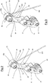
- the illustrated derailleur is a front derailleur and is wholly indicated with reference numeral 10.
- the front derailleur 10 is preferably a mechanical derailleur, in other words it does not need any electrical and/or electronic device for its operation.
- the derailleur 10 comprises a chain guide 11, which is configured to slidably engage a transmission chain of the bicycle (not illustrated) so as to move it from an inner position to an outer position crossing a plurality of intermediate positions between them.
- Predetermined positions of the chain guide 11 correspond to predetermined positions of the transmission chain on the crown gears of the crankset.
- the inner position of the chain guide 11 corresponds to a position of the transmission chain on the smallest crown gear of the crankset and the outer position corresponds to a position of the transmission chain on the largest crown gear of the crankset.
- the derailleur 10 comprises an inner end stop and an outer end stop (not illustrated) to limit the excursion of the chain guide 11.
- the movement of the chain guide 11 is actuated by a deformable quadrilateral 12.
- the deformable quadrilateral 12 comprises an inner connection element 13, an outer connection element 14, a fixed body 15 and a movable body 16.
- the chain guide 11 is fixedly connected to the movable body 16 of the deformable quadrilateral 12.
- the fixed body 15, the movable body 16 and the two connection elements 13, 14 are articulated to one another along four articulation axes A, B, C, D that are parallel to one another. More precisely, the fixed body 15 and the outer connection element 14 are articulated to one another according to a first articulation axis A; the outer connection element 14 and the movable body 16 are articulated to one another according to a second articulation axis B; the fixed body 15 and the inner connection element 13 are articulated to one another according to a third articulation axis C; the inner connection element 13 and the movable body 16 are articulated to one another according to a fourth articulation axis D.
- the movable body 16 comprises an inner plate 17 facing an outer plate 18 that make the chain guide 11.
- the movable body 16 is also provided with perforated flanges along the fourth articulation axis D for the connection to the inner connection element 13 and with perforated flanges for the connection to the outer connection element 14.
- the inner and outer connection elements 13, 14 are kinematically connecting rods, in other words they are elements that are not capable of transmitting pairs of forces to the elements to which they are connected along the respective articulation axes.
- the fixed body 15 comprises a collar 19 for attaching to a portion of the seat tube of the frame 101 of the bicycle, as schematically illustrated in figures 8 and 9 .
- the collar 19 allows the derailleur 10 to take up and maintain a predetermined position with respect to the crankset.
- the fixed body 15 can be fixedly connected to the seat tube of the frame of the bicycle without making use of the collar 19, for example welding the fixed body to the seat tube of the frame or constraining the fixed body 15 to an appendage directly formed in the seat tube of the frame.
- the derailleur 10 also comprises an actuation arm 20 hinged to the fixed body 15 about the first articulation axis A.
- the actuation arm 20 comprises a free end 20a at which a fastening system 21 of the control cable 100 is positioned.
- the actuation arm 20 rotates in a first angular direction E about the first articulation axis A, setting the outer connection element 14 in rotation with respect to the fixed body 15.
- This rotation of the actuation arm 20 and of the outer connection element 14 determines the deformation of the deformable quadrilateral 12 moving the chain guide 11 towards the outer position.
- the deformation of the deformable quadrilateral 12 takes place in contrast to a torsional return spring 22.
- the torsional return spring 22 is arranged on the fourth articulation axis D and is active between the movable body 16 and the inner connection element 13.
- the controlled release of the traction of the control cable 100 determines the deformation of the articulated quadrilateral 12 moving the chain guide 11 towards the inner position.
- the deformation of the articulated quadrilateral 12 takes place under the thrust of the torsional return spring 22.
- the actuation arm 20 can be an extension of the outer connection element 14 and can be made in one piece with it.
- the actuation arm 20 is physically distinct from the outer connection element 14.
- the actuation arm 20 is fixedly connected to the outer connection element 14 for rotations about the first articulation axis A.
- a torsional spring 23 acts with a preload, directed along a second angular direction opposite the first angular direction E, between the actuation arm 20 and the outer connection element 14.
- the torsional spring 23 opposes rotations along the first angular direction A of the actuation arm 20 with respect to the outer connection element 14.
- the actuation arm 20 and the outer connection element 14 behave like a rocker arm that oscillates about the first articulation axis A.
- the free end 20a of the actuation arm 20 is arranged going away from the first articulation axis A on the opposite side with respect to the second articulation axis B, as represented in figure 1 .
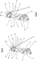
- the actuation arm 20 comprises, close to the free end 20a, a first surface 24 and a second end surface 25 which are opposite one another along a first direction F parallel to the first articulation axis A.
- the actuation arm 20 has a side surface 26 which joins together the first 24 and the second surface 25.
- the side surface 26 has a portion 27 which faces towards the third C and the fourth articulation axis D, in other words towards the fixed body 15.
- a cable-clamping washer 40 has an inner surface 41 intended to make contact with the actuation arm 20. Between the cable-clamping washer 40 and the actuation arm 20 a free end of the control cable 100 is arranged, so that the cable-clamping washer 40 locks the control cable 100 on the actuation arm 20.
- the cable-clamping washer 40 has a hole 42 arranged substantially at the center thereof.
- the free end 20a of the actuation arm 20 is also provided with a through hole (not visible in the attached figures) which passes through the actuation arm along the first direction F.
- the through hole in the actuation arm 20 extends between the first 24 and the second surface 25.
- a ferrule 30 is inserted inside the through hole, said through hole comprising a cylindrical inner cavity 31 open at both ends.
- the ferrule 30 can be equipped with a collar 32 (as illustrated in figure 8 ) or it can have a substantially cylindrical shape.
- the inner cavity 31 of the ferrule 30 is threaded to receive a bolt 32 which, engaging the hole 42 of the cable-clamping washer 40 locks the cable-clamping washer 40 on the actuation arm 20.
- the ferrule 30 is preferably made of steel and the actuation arm 20 is preferably made of aluminum or of an aluminum alloy.
- first 50 and a second 51 fastening station of the control cable 100 On the actuation arm 20, at the free end 20a there is a first 50 and a second 51 fastening station of the control cable 100.
- the first and the second fastening station 50, 51 are distinct from one another and have the function of making two different points or areas of application of the traction force of the control cable 100 on the actuation arm 20.
- the two points or areas of application of the traction force of the control cable 100 on the actuation arm 20 are arranged at different distances with respect to the plane P (the path of which is represented in figure 10 and 11 ) which contains both the first A and the second articulation axis B.
- the first 50 and the second fastening station 51 are arranged on the portion 27, facing towards the third C and fourth articulation axis D, of the side surface 26 of the actuation arm 20.
- the first fastening station 50 is arranged a shorter distance from the first articulation axis A with respect to the second fastening station 51, as represented in figures 2 to 7 .
- the holding seat 52 extends along the first direction F between the first 24 and the second surface 25 of the actuation arm 20.
- the holding seat 52 comprises a first insertion opening 52a arranged at an end of the holding seat 52.
- the first insertion opening 52a is formed on the first 24 or on the second surface 25 of the actuation arm 20.
- the holding seat 52 is open on the portion 27 of the side surface 26 of the actuation arm defining a groove.
- the holding seat 52 can be engaged by an anti-rotation appendage 43 of the cable-clamping washer 40.
- the anti-rotation appendage 43 extends substantially perpendicular to the inner surface 41 of the cable-clamping washer 40 and away from it.
- the anti-rotation appendage 43 projects from the outer edge 40a of the cable-clamping washer 40 joining to the edge itself.
- the anti-rotation appendage 43 has a first end 44 substantially aligned with an outer surface 45 opposite the inner surface 41 of the cable-clamping washer 40.
- a second end 46 of the anti-rotation appendage 43 is arranged going away from the inner surface 41 of the cable-clamping washer 40. The distance that separates the first 44 and the second end 46 of the anti-rotation appendage 43 defines the length of the appendage itself.
- the anti-rotation appendage 43 has a substantially prismatic shape in which the first 44 and the second 46 end are parallel to one another.
- the insertion of the anti-rotation appendage 43 in the holding seat 52 determines a stable and predetermined angular position of the cable-clamping washer 40 with respect to the actuation arm 20.
- the insertion of the anti-rotation appendage 43 in the holding seat 52 also determines a first contact surface 53 for the control cable 100.
- the first contact surface 53 defines a point or area of application of the traction force of the control cable 100 on the actuation arm 20.
- the first fastening station 50 can be used to fasten the control cable 100 to the actuation arm 20, making the first fastening station 50 operative.
- the first contact surface 53 is arranged on an upper surface 47 of the anti-rotation appendage 43 facing towards the second fastening station 51.
- the first contact surface 53 is arranged on an upper surface 47 of the anti-rotation appendage 43 facing the opposite way with respect to the first articulation axis A.
- the holding seat 52 and the first contact surface 53 are oriented so as not to deviate the path of the control cable 100 or to deviate it by a few degrees (comprised between 0° and 15°).
- the holding seat 52 and the first contact surface 53 make it possible to constrain the control cable 100 on the actuation arm 20 so that the portion of control cable held between the cable-clamping washer 40 and the actuation arm 20 is substantially aligned with, or inclined by a few degrees with respect to, the portion of control cable 100 that reaches the derailleur 10.
- the first contact surface 53 is defined by the portion of anti-rotation appendage 43 that deviates the path of the control cable 100, or that, in the case in which the control cable 100 is not deviated, is in contact with the control cable 100.
- the further holding seat 54 extends along the first direction F between the first 24 and the second surface 25 of the actuation arm 20 in a position further from the first articulation axis A with respect to the holding seat 52.
- the further holding seat 54 comprises a first insertion opening 54a arranged at an end of the further holding seat 54.
- the first insertion opening 54a is formed on the first 24 or the second surface 25 of the actuation arm 20.
- the further holding seat 54 is open on the portion 27 of the side surface 26 of the actuation arm defining a groove.
- the further holding seat 54 is engageable by the anti-rotation appendage 43 of the cable-clamping washer 40.
- the insertion of the anti-rotation appendage 43 in the further holding seat 54 determines a stable and predetermined angular position of the cable-clamping washer 40 with respect to the actuation arm 20.
- the insertion of the anti-rotation appendage 43 in the further holding seat 54 makes a second contact surface 55 for the control cable 100.
- the second contact surface 55 defines a point or area of application of the traction force of the control cable 100 on the actuation arm 20.
- the second fastening station 51 can be used to fasten the control cable 100 to the actuation arm 20, making the second fastening station 51 operative.
- the second contact surface 55 is arranged on a side surface 48 of the anti-rotation appendage 43 facing the opposite way with respect to the further holding seat 54.
- the further holding seat 54 and the second contact surface 55 are oriented so as to significantly deviate (by more than 15°) the path of the control cable 100.
- the further holding seat 54 and the second contact surface 55 make it possible to constrain the control cable 100 on the actuation arm 20 so that the portion of control cable held between the cable-clamping washer 40 and the actuation arm 20 is significantly inclined with respect to the portion of control cable 100 that reaches the derailleur 10.
- the second contact surface 55 is defined by the portion of anti-rotation appendage 43 that deviates the path of the control cable 100.
- the first contact surface 53 is arranged a shorter distance with respect to the second contact surface 55 from the plane P that contains both the first A and the second articulation axis B.
- the movement ratio determined by the first contact surface 53 is greater than the movement ratio determined by the second contact surface 55.
- the cable-clamping washer 40 foresees at least one, preferably two, cable-guiding grooves 49a and 49b defined on the inner surface 41 thereof, to accompany in a held manner the portion of control cable 100 arranged between the cable-clamping washer 40 itself and the actuation arm 20.
- the first cable-guiding groove 49a extends perpendicular to the anti-rotation appendage 43 and crosses the entire inner surface 41 opening at both ends on the outer edge 40a of the cable-clamping washer 40.
- the depth of the first cable-guiding groove 49a is substantially constant along the entire extension of the groove itself.
- the depth of the first cable-guiding groove 49a is smaller than the diameter of the control cable 100.
- the second cable-guiding groove 49b extends perpendicular to the anti-rotation appendage 43 and crosses the entire inner surface 41 opening at both ends on the outer edge 40a of the cable-clamping washer 40.
- the depth of the second cable-guiding groove 49b is substantially constant along the entire extension of the groove itself.
- the depth of the second cable-guiding groove 49b is smaller than the diameter of the control cable 100.
- the depths of the first 49a and second cable-guiding groove 49b are substantially identical.
- the first 49a and the second cable-guiding groove 49b are parallel to one another and have substantially identical length.
- the first 49a and the second cable-guiding groove 49b are arranged on opposite sides of the hole 42 of the cable-clamping washer 40.
- the further holding seat 54 is engaged by a further anti-rotation appendage 70 of the cable-clamping washer 40.
- the cable-clamping washer 40 comprises two anti-rotation appendages 43, 70, as schematically indicated in figure 9A .
- the insertion of the further anti-rotation appendage 70 in the further holding seat 54 contributes to determining a stable and predetermined angular position of the cable-clamping washer 40 with respect to the actuation arm 20.
- the insertion of the further anti-rotation appendage 70 in the further holding seat 54 makes a second contact surface 71 for the control cable 100.
- the second contact surface 71 defines a point or area of application of the traction force of the control cable 100 on the actuation arm 20.
- the further anti-rotation appendage 70 inserted in the further holding seat 54 makes the second fastening station 51 available for fastening the control cable 100 to the actuation arm 20.
- the further anti-rotation appendage 70 is substantially identical in shape and size to the anti-rotation appendage 43.
- the further anti-rotation appendage 70 extends from the outer edge 40a of the cable-clamping washer 40 on the same side as the anti-rotation appendage 40 and is angularly spaced from the latter along the outer edge 40a, as represented in figure 9A .
- the second contact surface 71 is arranged on a side surface 72 of the anti-rotation appendage 43.
- the further holding seat 54 and the second contact surface 71 are oriented so as to significantly deviate the path of the control cable 100 (by more than 15°).
- the further holding seat 54 and the second contact surface 71 make it possible to constrain the control cable 100 on the actuation arm 20 so that the portion of control cable held between the cable-clamping washer 40 and the actuation arm 20 is inclined with respect to the portion of control cable 100 that reaches the derailleur 10.
- the second contact surface 71 is defined by the portion of anti-rotation appendage 70 that deviates the path of the control cable 100.
- the first contact surface 53 is arranged a shorter distance with respect to the second contact surface 71 from the plane P that contains both the first A and the second articulation axis B.
- the movement ratio determined by the first contact surface 53 is greater than the movement ratio determined by the second contact surface 71.
- the first cable-guiding groove extends perpendicular to the anti-rotation appendage 43 and crosses the entire inner surface 41 opening at both ends on the outer edge 40a of the cable-clamping washer 40.
- the depth of the first cable-guiding groove is substantially constant along the entire extension of the groove itself.
- the depth of the first cable-guiding groove is smaller than the diameter of the control cable 100.
- the second cable-guiding groove extends perpendicular to the further anti-rotation appendage 70 and crosses the entire inner surface 41 opening at both ends on the outer edge 40a of the cable-clamping washer 40.
- the depth of the second cable-guiding groove is substantially constant along the entire extension of the groove itself.
- the depth of the second cable-guiding groove is smaller than the diameter of the control cable 100.
- the depths of the first and second cable-guiding groove 49b are substantially identical.
- the first and second cable-guiding groove are at an angle, in other words they intersect one another.
- first and/or second cable-guiding grooves are formed on the actuation arm 20.
- the projection 60 extends along the first direction F and is arranged a greater distance from the first articulation axis A with respect to the holding seat 52.
- the projection 60 comprises at least one first portion 60a extending beyond the first 24 or the second surface 25 of the actuation arm 20 along the first direction F.
- the projection 60 has an elongated shape that extends along the first direction F.
- the projection 60 acts as a cable-bending element for the control cable 100.
- the projection 60 has a second contact surface 61 which deviates the path of the control cable 100 before it reaches the cable-clamping washer 40 to be held on the actuation arm 20.
- the second contact surface 61 is arranged on a front surface 62 of the projection 60 facing the opposite way with respect to the cable-clamping washer 40 and preferably arranged at the first portion 60a.
- the projection 60 and the second contact surface 61 are oriented so as to significantly deviate the path of the control cable 100 (by more than 15°).
- the projection 60 and the second contact surface 61 make it possible to constrain the control cable 100 on the actuation arm 20 so that the portion of control cable held between the cable-clamping washer 40 and the actuation arm 20 is inclined with respect to the portion of control cable 100 that reaches the derailleur 10.
- the first contact surface 53 is arranged a shorter distance with respect to the second contact surface 61 from the plane P that contains both the first A and the second articulation axis B.
- the movement ratio determined by the first contact surface 53 is greater than the movement ratio determined by the second contact surface 61.
- the cable-guiding groove 24a crosses the entire first surface 24 of the actuation arm along a direction perpendicular to the first direction F.
- the depth of the cable-guiding groove 24a is substantially constant along the entire extension of the groove itself.
- the depth of the cable-guiding groove 24a is smaller than the diameter of the control cable 100.
- the cable-guiding groove 24a extends from the projection 60 and proceeds with an inclination with respect to the direction of extension of the projection 60, so as to guide the control cable 100 after the deviation actuated by the projection 60.
- control cable 100 is fastened to the actuation arm at the first fastening station 50.
- the anti-rotation appendage 43 of the cable-clamping washer 40 is introduced in the insertion opening 52a of the holding seat 52 with the control cable 100 that, resting on the anti-rotation appendage 43, is inserted in a cable-guiding groove 49a of the cable-clamping washer 40.
- the resting area of the control cable 100 on the anti-rotation appendage 43 defines the first contact surface 53.
- the hole 42 of the cable-clamping washer 40 is engaged by the bolt 32 which is screwed into the ferrule 30 inserted in the through hole in the actuation arm 20.
- the head 32a thereof presses the cable-clamping washer 40 against the first surface 24 of the actuation arm 20 stably constraining the control cable 100.
- control cable 100 is fastened to the actuation arm at the second fastening station 51.
- the anti-rotation appendage 43 of the cable-clamping washer 40 is inserted in the insertion opening 54a of the further holding seat 54 with the control cable 100 that, resting on the anti-rotation appendage 43, is inserted in a cable-guiding groove 49a of the cable-clamping washer 40.
- the resting area of the control cable 100 on the anti-rotation appendage 43 defines the second contact surface 55.
- the hole 42 of the cable-clamping washer 40 is engaged by the bolt 32 which is screwed into the ferrule 30 inserted in the through hole in the actuation arm 20.
- the head 32a thereof presses the cable-clamping washer 40 against the respective surface 24 of the actuation arm 20 stably constraining the control cable 100.
- the further anti-rotation appendage 70 of the cable-clamping washer 40 is already inserted in the insertion opening 54a of the further holding seat 54 with the control cable 100 that, resting on the further anti-rotation appendage 70, is inserted in a cable-guiding groove.
- the resting area of the control cable 100 on the further anti-rotation appendage 70 defines the second contact surface 71.
- the hole 42 of the cable-clamping washer 40 is engaged by the bolt 32 which is screwed into the ferrule 30 inserted in the through hole in the actuation arm 20.
- the head 32a thereof presses the cable-clamping washer 40 against the respective surface of the actuation arm 20 stably constraining the control cable 100.
- control cable 100 is arranged resting on the portion 60a of the projection 60 that projects beyond the first 24 or the second surface 25 of the actuation arm.
- the cable-clamping washer 40 is positioned on the corresponding surface 24 of the actuation arm 20 and the anti-rotation appendage 43 is inserted in the first insertion opening 52a of the holding seat 52.
- the hole 42 of the cable-clamping washer 40 is engaged by the bolt 32 which is screwed into the ferrule 30 inserted in the through hole in the actuation arm 20.
Landscapes
- Engineering & Computer Science (AREA)
- Chemical & Material Sciences (AREA)
- Combustion & Propulsion (AREA)
- Transportation (AREA)
- Mechanical Engineering (AREA)
- Flexible Shafts (AREA)
- Tires In General (AREA)
- Clamps And Clips (AREA)
Applications Claiming Priority (1)
| Application Number | Priority Date | Filing Date | Title |
|---|---|---|---|
| IT102017000021438A IT201700021438A1 (it) | 2017-02-24 | 2017-02-24 | Deragliatore per bicicletta |
Publications (1)
| Publication Number | Publication Date |
|---|---|
| EP3366565A1 true EP3366565A1 (en) | 2018-08-29 |
Family
ID=59101621
Family Applications (1)
| Application Number | Title | Priority Date | Filing Date |
|---|---|---|---|
| EP18158275.0A Withdrawn EP3366565A1 (en) | 2017-02-24 | 2018-02-23 | Bicycle derailleur |
Country Status (6)
| Country | Link |
|---|---|
| US (1) | US10822051B2 (enExample) |
| EP (1) | EP3366565A1 (enExample) |
| JP (1) | JP7015187B2 (enExample) |
| CN (1) | CN108557001A (enExample) |
| IT (1) | IT201700021438A1 (enExample) |
| TW (1) | TW201838871A (enExample) |
Families Citing this family (4)
| Publication number | Priority date | Publication date | Assignee | Title |
|---|---|---|---|---|
| IT201700021394A1 (it) * | 2017-02-24 | 2018-08-24 | Campagnolo Srl | Deragliatore per bicicletta |
| CN109592314A (zh) * | 2018-11-21 | 2019-04-09 | 程大军 | 一种精密分度盘输送装置 |
| US11981398B2 (en) * | 2020-09-11 | 2024-05-14 | Shimano Inc. | Bicycle derailleur |
| DE102022003491A1 (de) | 2022-05-13 | 2023-11-16 | Shimano Inc. | Fahrradkomponente |
Citations (7)
| Publication number | Priority date | Publication date | Assignee | Title |
|---|---|---|---|---|
| US4362522A (en) * | 1978-12-04 | 1982-12-07 | Huret Roger H M | Derailleur for a chainwheel assembly for a bicycle |
| US4507101A (en) * | 1982-04-07 | 1985-03-26 | Shimano Industrial Company Limited | Speed control device for a bicycle |
| US5037355A (en) * | 1989-09-28 | 1991-08-06 | Maeda Industries, Ltd. | Bicycle front derailleur |
| US20020033067A1 (en) * | 1999-05-27 | 2002-03-21 | Takeshi Takachi | Cable connecting apparatus for a bicycle component |
| US20080026891A1 (en) * | 2006-07-31 | 2008-01-31 | Shimano Inc. | Bicycle rear derailleur |
| EP3000711A1 (en) | 2011-10-03 | 2016-03-30 | Shimano Inc. | Bicycle front derailleur with a variable actuation ratio |
| US20160121967A1 (en) * | 2014-10-31 | 2016-05-05 | Shimano Inc. | Bicycle derailleur |
Family Cites Families (14)
| Publication number | Priority date | Publication date | Assignee | Title |
|---|---|---|---|---|
| JPS5386751U (enExample) * | 1976-12-16 | 1978-07-17 | ||
| JPH0535920Y2 (enExample) | 1989-09-05 | 1993-09-10 | ||
| JPH0546692U (ja) * | 1991-11-29 | 1993-06-22 | マエダ工業株式会社 | 自転車用フロントディレーラ |
| EP0653347B1 (en) | 1993-11-12 | 2000-03-01 | Shimano Inc. | Front gear for a bicycle |
| US6629903B1 (en) * | 2000-04-17 | 2003-10-07 | Shimano Inc. | Bicycle derailleur |
| US6491597B2 (en) | 2001-05-07 | 2002-12-10 | Falcon Industrial Co., Ltd. | Front speed changing device |
| US7081058B2 (en) | 2003-02-12 | 2006-07-25 | Shimano Inc. | Bicycle front derailleur |
| JP4145836B2 (ja) * | 2004-06-15 | 2008-09-03 | 株式会社シマノ | 自転車用変速駆動装置 |
| US7438658B2 (en) * | 2004-08-30 | 2008-10-21 | Shimano Inc. | Bicycle front derailleur |
| US7597638B2 (en) | 2004-08-31 | 2009-10-06 | Sram, Llc | Transmission |
| TWM419728U (en) | 2011-05-19 | 2012-01-01 | Shimano Kk | Cable fixing structure |
| US9127766B2 (en) | 2012-11-07 | 2015-09-08 | Shimano Inc. | Bicycle derailleur |
| US10065705B2 (en) * | 2015-02-05 | 2018-09-04 | Shimano Inc. | Bicycle derailleur |
| IT201700021394A1 (it) * | 2017-02-24 | 2018-08-24 | Campagnolo Srl | Deragliatore per bicicletta |
-
2017
- 2017-02-24 IT IT102017000021438A patent/IT201700021438A1/it unknown
-
2018
- 2018-02-22 JP JP2018029375A patent/JP7015187B2/ja active Active
- 2018-02-22 TW TW107105943A patent/TW201838871A/zh unknown
- 2018-02-22 US US15/902,226 patent/US10822051B2/en active Active
- 2018-02-23 EP EP18158275.0A patent/EP3366565A1/en not_active Withdrawn
- 2018-02-24 CN CN201810156747.4A patent/CN108557001A/zh active Pending
Patent Citations (7)
| Publication number | Priority date | Publication date | Assignee | Title |
|---|---|---|---|---|
| US4362522A (en) * | 1978-12-04 | 1982-12-07 | Huret Roger H M | Derailleur for a chainwheel assembly for a bicycle |
| US4507101A (en) * | 1982-04-07 | 1985-03-26 | Shimano Industrial Company Limited | Speed control device for a bicycle |
| US5037355A (en) * | 1989-09-28 | 1991-08-06 | Maeda Industries, Ltd. | Bicycle front derailleur |
| US20020033067A1 (en) * | 1999-05-27 | 2002-03-21 | Takeshi Takachi | Cable connecting apparatus for a bicycle component |
| US20080026891A1 (en) * | 2006-07-31 | 2008-01-31 | Shimano Inc. | Bicycle rear derailleur |
| EP3000711A1 (en) | 2011-10-03 | 2016-03-30 | Shimano Inc. | Bicycle front derailleur with a variable actuation ratio |
| US20160121967A1 (en) * | 2014-10-31 | 2016-05-05 | Shimano Inc. | Bicycle derailleur |
Non-Patent Citations (1)
| Title |
|---|
| - -: "Campagnolo Umwerfer-Schaltzugplatte für Escape/QS(TM) Ergopo", 31 December 2009 (2009-12-31), https://www.bike-components.de, XP055419240, Retrieved from the Internet <URL:https://www.bike-components.de/en/Campagnolo/Umwerfer-Schaltzugplatte-fuer-Escape-QS-Ergopower-Modell-2008-2009-p43338/> [retrieved on 20171025] * |
Also Published As
| Publication number | Publication date |
|---|---|
| CN108557001A (zh) | 2018-09-21 |
| TW201838871A (zh) | 2018-11-01 |
| US20180244347A1 (en) | 2018-08-30 |
| JP7015187B2 (ja) | 2022-02-02 |
| JP2018158715A (ja) | 2018-10-11 |
| US10822051B2 (en) | 2020-11-03 |
| IT201700021438A1 (it) | 2018-08-24 |
Similar Documents
| Publication | Publication Date | Title |
|---|---|---|
| US10822051B2 (en) | Bicycle derailleur | |
| US9045193B2 (en) | Command device for a derailleur of a bicycle | |
| US5728018A (en) | Method and apparatus for positioning a bicycle derailleur chain guide | |
| EP2065297B1 (en) | Bicycle rear derailleur | |
| US20070191159A1 (en) | Bicycle derailleur | |
| CN100560425C (zh) | 前拨链器及其安装件 | |
| US9248885B2 (en) | Derailleur | |
| EP2769907A1 (en) | Bicycle gearshift with improved precision control | |
| US8029396B2 (en) | Front derailleur for a bicycle | |
| EP2192032A1 (en) | Fixing device | |
| US20150094177A1 (en) | Derailleur | |
| JP2008195381A (ja) | 自転車部品ポジショニング装置 | |
| EP1726519A2 (en) | Bicycle front derailleur | |
| EP3272634B1 (en) | Bicycle gearshift | |
| EP3366566B1 (en) | Bicycle derailleur | |
| EP1571076A1 (en) | Device for the attachment of a derailleur to a bicycle and derailleur comprising such an attachment device | |
| EP3360765B1 (en) | Device for actuating the front derailleur of a bicycle | |
| EP2520480B1 (en) | Bicycle front derailleur body and device for adjustable rest fo such derailleur body on a tube of a bicycle frame | |
| EP3360770B1 (en) | Front derailleur for a bicycle | |
| EP2078667B1 (en) | Bicycle shift operating device |
Legal Events
| Date | Code | Title | Description |
|---|---|---|---|
| PUAI | Public reference made under article 153(3) epc to a published international application that has entered the european phase |
Free format text: ORIGINAL CODE: 0009012 |
|
| STAA | Information on the status of an ep patent application or granted ep patent |
Free format text: STATUS: THE APPLICATION HAS BEEN PUBLISHED |
|
| AK | Designated contracting states |
Kind code of ref document: A1 Designated state(s): AL AT BE BG CH CY CZ DE DK EE ES FI FR GB GR HR HU IE IS IT LI LT LU LV MC MK MT NL NO PL PT RO RS SE SI SK SM TR |
|
| AX | Request for extension of the european patent |
Extension state: BA ME |
|
| STAA | Information on the status of an ep patent application or granted ep patent |
Free format text: STATUS: REQUEST FOR EXAMINATION WAS MADE |
|
| 17P | Request for examination filed |
Effective date: 20190219 |
|
| RBV | Designated contracting states (corrected) |
Designated state(s): AL AT BE BG CH CY CZ DE DK EE ES FI FR GB GR HR HU IE IS IT LI LT LU LV MC MK MT NL NO PL PT RO RS SE SI SK SM TR |
|
| STAA | Information on the status of an ep patent application or granted ep patent |
Free format text: STATUS: EXAMINATION IS IN PROGRESS |
|
| 17Q | First examination report despatched |
Effective date: 20200225 |
|
| GRAP | Despatch of communication of intention to grant a patent |
Free format text: ORIGINAL CODE: EPIDOSNIGR1 |
|
| STAA | Information on the status of an ep patent application or granted ep patent |
Free format text: STATUS: GRANT OF PATENT IS INTENDED |
|
| INTG | Intention to grant announced |
Effective date: 20210128 |
|
| STAA | Information on the status of an ep patent application or granted ep patent |
Free format text: STATUS: THE APPLICATION IS DEEMED TO BE WITHDRAWN |
|
| 18D | Application deemed to be withdrawn |
Effective date: 20210608 |