EP3366379A1 - Transport device for processing tv frames, facility with processing units for processing tv frames and method for processing tv frames - Google Patents
Transport device for processing tv frames, facility with processing units for processing tv frames and method for processing tv frames Download PDFInfo
- Publication number
- EP3366379A1 EP3366379A1 EP17157727.3A EP17157727A EP3366379A1 EP 3366379 A1 EP3366379 A1 EP 3366379A1 EP 17157727 A EP17157727 A EP 17157727A EP 3366379 A1 EP3366379 A1 EP 3366379A1
- Authority
- EP
- European Patent Office
- Prior art keywords
- horizontal
- vertical
- positioning
- transportation device
- coupling means
- Prior art date
- Legal status (The legal status is an assumption and is not a legal conclusion. Google has not performed a legal analysis and makes no representation as to the accuracy of the status listed.)
- Withdrawn
Links
Images


Classifications
-
- B—PERFORMING OPERATIONS; TRANSPORTING
- B05—SPRAYING OR ATOMISING IN GENERAL; APPLYING FLUENT MATERIALS TO SURFACES, IN GENERAL
- B05B—SPRAYING APPARATUS; ATOMISING APPARATUS; NOZZLES
- B05B13/00—Machines or plants for applying liquids or other fluent materials to surfaces of objects or other work by spraying, not covered by groups B05B1/00 - B05B11/00
- B05B13/02—Means for supporting work; Arrangement or mounting of spray heads; Adaptation or arrangement of means for feeding work
- B05B13/0285—Stands for supporting individual articles to be sprayed, e.g. doors, vehicle body parts
-
- B—PERFORMING OPERATIONS; TRANSPORTING
- B05—SPRAYING OR ATOMISING IN GENERAL; APPLYING FLUENT MATERIALS TO SURFACES, IN GENERAL
- B05B—SPRAYING APPARATUS; ATOMISING APPARATUS; NOZZLES
- B05B13/00—Machines or plants for applying liquids or other fluent materials to surfaces of objects or other work by spraying, not covered by groups B05B1/00 - B05B11/00
- B05B13/02—Means for supporting work; Arrangement or mounting of spray heads; Adaptation or arrangement of means for feeding work
- B05B13/04—Means for supporting work; Arrangement or mounting of spray heads; Adaptation or arrangement of means for feeding work the spray heads being moved during spraying operation
- B05B13/0431—Means for supporting work; Arrangement or mounting of spray heads; Adaptation or arrangement of means for feeding work the spray heads being moved during spraying operation with spray heads moved by robots or articulated arms, e.g. for applying liquid or other fluent material to three-dimensional [3D] surfaces
-
- B—PERFORMING OPERATIONS; TRANSPORTING
- B05—SPRAYING OR ATOMISING IN GENERAL; APPLYING FLUENT MATERIALS TO SURFACES, IN GENERAL
- B05B—SPRAYING APPARATUS; ATOMISING APPARATUS; NOZZLES
- B05B13/00—Machines or plants for applying liquids or other fluent materials to surfaces of objects or other work by spraying, not covered by groups B05B1/00 - B05B11/00
- B05B13/02—Means for supporting work; Arrangement or mounting of spray heads; Adaptation or arrangement of means for feeding work
- B05B13/04—Means for supporting work; Arrangement or mounting of spray heads; Adaptation or arrangement of means for feeding work the spray heads being moved during spraying operation
- B05B13/0447—Installation or apparatus for applying liquid or other fluent material to conveyed separate articles
-
- B—PERFORMING OPERATIONS; TRANSPORTING
- B05—SPRAYING OR ATOMISING IN GENERAL; APPLYING FLUENT MATERIALS TO SURFACES, IN GENERAL
- B05B—SPRAYING APPARATUS; ATOMISING APPARATUS; NOZZLES
- B05B13/00—Machines or plants for applying liquids or other fluent materials to surfaces of objects or other work by spraying, not covered by groups B05B1/00 - B05B11/00
- B05B13/02—Means for supporting work; Arrangement or mounting of spray heads; Adaptation or arrangement of means for feeding work
- B05B13/0221—Means for supporting work; Arrangement or mounting of spray heads; Adaptation or arrangement of means for feeding work characterised by the means for moving or conveying the objects or other work, e.g. conveyor belts
- B05B13/0271—Means for supporting work; Arrangement or mounting of spray heads; Adaptation or arrangement of means for feeding work characterised by the means for moving or conveying the objects or other work, e.g. conveyor belts the object or work standing still during the spraying operation
Definitions
- the present invention refers according to claim 1 to a transportation device for transporting of at least one object, according to claim 12 to a facility and according to claim 14 to a method for transporting an object to be processed.
- robot programing for processing, in particular painting is prepared for a master fixture, in particular TV frame fixture. Robot will follow the same path as it's programmed. For accurate painting application, all objects, in particular TVs, with same dimension and model must be placed on to fixture as it is.
- Document EP0646418A1 discloses a full automatic coating system.
- This system includes an endless metal tape driven to run in one direction along an endless traveling path, a product supplying station for automatically selecting products of a desired type and supplying them to the endless metal tape according to a production control procedure stored in a control unit, a coating station disposed in the traveling path downstream of the product supplying station and including a spray gun for selectively spraying one of coatings of different colors according to instructions received from the control unit, a drying and baking station and a coating removing station disposed in the traveling path downstream of the coating station in the order named. All the components are linked to operate in timed relation to one another according to the instructions received from the control unit.
- the coating system thus constructed is compact in size, inexpensive to manufacture, and capable of automatically coating such a small quantity of products which conventionally required manual coating operation.
- EP0646418A1 does not mention any spring hanger system used in the dyeing system to fix television frames from a universal dyeing system that is compatible with each television.
- fixture design is not well enough for the spray operation, there will be either some parts not painted or some areas painted too much.
- robot programing is finished, the same parts on the different fixtures must be in the same place.
- the spray robot is operating on a path, which should be all the same for any fixtures. When the fixtures have a wide variety in size, the robot can hit the substrate. There are operational and process risks regarding the fixture design.
- an advanced transportation device for transporting of at least one object an advanced facility with such a transportation device and an advanced method for transporting objects to be processes.
- a transportation device for transporting of at least one object that enables a decrease of fixture changing time.
- Transportation device for transporting of at least one object, in particular a TV frame, to be coated though a coating facility, at least comprising a vertical positioning means for positioning the object on a predefined height, a horizontal positioning means for positioning the object in a predefined alignment with respect to the main frame, wherein the vertical positioning means comprises a vertical configuration means for adjusting the vertical position of a vertical coupling means and wherein the horizontal positioning means comprises at least two horizontal coupling means for coupling with the object and a horizontal configuration means for adjusting the distance between the horizontal coupling means in horizontal direction.
- the vertical and horizontal positioning means can be also considered as fixture.
- a universal fixture works for different objects, in particular all models and sizes of TV frames.
- the universal fixture design can work with any TV frame, preferably without any change on it.
- the horizontal positioning means comprises at least one spring element, in particularly a screw spring preferably made of metal, wherein at least one horizontal coupling means and preferably both horizontal coupling means are spring-loaded by said spring element.
- Each horizontal coupling means is according to a further preferred embodiment of the present invention arranged on a movable rod, wherein the movable rod is moveable in horizontal direction, wherein the movable rods are at least sectionally arranged inside a guide means and coupled to said spring element.
- This embodiment is beneficial since a reliable guide is provided.
- At least or exactly two locking members are provided, wherein the locking members are arranged in or on or as part of the guide means, wherein one locking member is arranged in a section of guide means in which one rod is arranged, and wherein the other locking member is arranged in another section of the guide means in which the other rod is arranged, wherein a relative movement between each rod and guide means can be limited, in particularly prevented, in particular due to form closure or force fit.
- the locking control means preferably comprises mechanical parts for operating the locking means respectively locking members.
- the locking control means comprises according to a further preferred embodiment of the present invention an actuation element for introducing mechanical forces into the locking control means for operating both locking means respectively both locking members at the same time.
- a force introduced via locking control means is preferably directed to locking members for locking or releasing.
- This embodiment is beneficial since no electric motor or pneumatic or hydraulic actuator actuators are required, in particular with respect to high temperatures this mechanical solution is very reliable.
- This embodiment is further beneficial since due to a mechanical counterpart (that interacts with locking control means) non-human related operation fixing and/or fixing control can take place.
- the mechanical counterpart is preferably arranged in stationary manner and the transportation device preferably passes the mechanical counterpart, in a predefined relative position between transportation device and counterpart an actuation of locking control member takes place.
- the vertical positioning means extends according to a further preferred embodiment of the present invention along an arm-member, wherein at least one vertical coupling means for supporting the object in vertical direction is part of the arm-member.
- the arm-member preferably comprises a fixing means, wherein the vertical coupling means is movable in vertical direction and wherein the position of the vertical coupling means is fixable by the fixing means.
- Vertical adjustment can be carried out in stepwise or step less manner. This embodiment is beneficial since a very precise and easy vertical adjustment is provided.
- the arm-member is according to a further preferred embodiment of the present invention inclined to the vertical direction in an angle between 2° and 85°, in particular in an angle between 5° and 65° or between 10° and 35°.
- This embodiment is beneficial since the object can be aligned in such a manner that coating respectively painting can be applied easily.
- a main frame is provided, wherein the vertical position means and the horizontal positioning means are arranged at the main frame. Additionally or alternatively a plurality of wheels, in particular at least three wheels or four wheels, are provided, wherein the wheels are arranged in a lower section of the main frame, wherein the positioning means is arranged at an upper section of the main frame, wherein the upper section is above the lower section.
- the before mentioned object is also solved by a facility according to claim 12.
- the facility according to the present invention preferably comprises at least a multi axis robot arm, wherein a coating, in particular spraying, unit is attached to the robot arm and multiple transportation devices according to any of the before mentioned claims.
- a transportation path for transporting the transportation devices is preferably provided.
- the transportation path preferably comprises rails, in particularly arranged on the ground or above the ground.
- further handling stations are provided along the transportation path, wherein one further handling station is a curing oven and/or wherein another handling station is a cleaning station for cleaning the object, in particularly before coating.
- the before mentioned object is also solved by a method for processing, in particular coating, objects.
- the method according to the present invention preferably comprises at least the steps: Providing a transportation device for transporting an object, in particularly according to any of claims 1 to 11; Positioning the object, wherein a vertical positioning takes place by means of a vertical positioning means for positioning the object on a predefined height and wherein a horizontal positioning takes place by a vertical positioning means for positioning the object in a predefined alignment with respect to a main frame, wherein the vertical positioning means comprises a vertical configuration means for adjusting the vertical position of the vertical positioning means and wherein the horizontal positioning means comprises at least two horizontal coupling means for coupling with the object and a horizontal configuration means for adjusting the distance between the horizontal coupling means in horizontal direction; Processing the object with a processing unit, wherein a stationary robot arm comprises the processing unit, wherein the processing unit is movable by said robot arm with multiple degrees of freedom, in particularly with up to 3 degrees of freedom or with more than 3 degrees of freedom or with up to 4 degrees of freedom
- This method is beneficial since it enables a standard spray paint operation for any TV frame. It further provides an opportunity for flexible automation for any additional operation like curing, cleaning, cooling and inspection for TV frames.
- the transportation device holding the processed object is moved according to a further preferred embodiment of the present invention inside a curing oven.
- This embodiment is beneficial since the frame remains on the transportation device during curing, thus no further loading or unloading is required.
- Fig. 1 shows an example of a facility, wherein said facility comprises a plurality of transportation devices 40, which are transported along a defined path 11.
- Said path 11 preferably comprises rails, wherein each transportation device 40 preferably has a wheel part 8 and wheels of said wheel part are running inside said rails.
- the facility preferably comprises multiple processing stations for processing the object 3, in particular TV frame.
- One station can be a coating station 44, in particular spray painting station, a further station can be a cleaning station 15 and a further station can be a heating, in particular curing oven, station.
- conveyor 11 is moving fixture respectively transportation device 40 with fixture arrives at spring releasing point 12 while fixture holds object 3, in particular TV frame.
- a fixed part respectively stationary part in particularly arranged at a wall or stationary frame, will touch the spring locking device 6.
- the left fixing pin 16 and right fixing pin 17 are released from spring element 20.
- TV frame After TV frame is painted and cured it's removed from fixture and side rods are fixed to locking position for next process. And it's so simple that doesn't need any sensors, electrical equipment or pneumatic equipment.
- Present design is a cost saving method avoids producing many different fixtures for all size and group of TV frames.
- Present design also enables standard spray paint application. This helps system to make flexible design changes for other equipment's like oven, ionization to make system more effective and flexible.
- Objects 3 are preferably arranged on transportation devices 40 before said transportation devices 40 are entering a cleaning station 15. After cleaning a spring release means 13 preferably releases spring element 20, hence a predefined alignment of the object 3 with respect to main frame 4 results. In a later step a movement of spring element 20 is preferably reduced or stopped by spring fixing means 12. In a further station 44 a surface processing, in particular coating, takes place, wherein a robot arm 1 preferably guides a processing unit 2 along pre-programed paths. In an oven 14 curing of said coating takes place. After curing all transportation devices 40 carrying objects 3 are channeled out or all objects 3 are removed from these transportation devices 40. Thus, preferably a continuous conveyor system robot programing for painting is prepared for master TV frame.
- Fig. 2 gives an idea how an object 3, in particular TV frame, must be hang on a fixture, wherein such a fixture preferably comprises a horizontal positioning means 30 and a vertical positioning means 25.
- the relative position between an object 3 and a main frame 4 are preferably fix during transportation and/or processing.
- dimensions are preferably stable for all fixtures transported on the continuous conveyor 11.
- an arm-member 42 is provided, wherein said arm-member preferably forms or comprises the vertical positioning means 30.
- the vertical positioning means 30 preferably comprises vertical coupling means 7 for holding the object 3 and vertical configuration means 32 for adjusting the vertical position of vertical coupling means 7. It is hereby possible that vertical configuration means 32 enables a stepwise or step less configuration.
- Arm-member 42 is preferably at least sectionally rotatable or pivotable around a horizontal axis. Arm-member 42 is preferably coupled via a forwarding spring 5 with main frame 4 or horizontal positioning means 25. Spring 5 preferably applies forces onto arm-member in said rotating respectively pivoting direction.
- the arm-member 42 is preferably inclined respectively pivotable to the vertical direction in an angle between 0° and 90°, in particular in an angle between 2° and 75° or 5° and 60° or 15° and 45°.
- X 9 and Y 10 distances are preferably the same or must be same for all TV frames of the same kind.
- the present invention provides a universal fixture for all sizes of TV frames (in particular between 32"-65" or between 20"-150").
- Fig. 4 shows that spring element 20 touches the left and right inner side of the TV frames with its fixing rods.
- Said fixing rods applies forces to contact surfaces of the object 3, thus the object moves in horizontal direction to bring the forces applied by first rod and second rod in an equilibrium. And it makes it possible to have the same length from side to middle.
- This mechanical assembly of fixing structure does not affect paint dust, Ionization system blowing air, curing oven temperature and manpower.
- the facility and/or one or some or all individual stations, in particular coating station 44, oven station 14 or cleaning station 15 or transporting along path 11, is/are preferably working without any human control.
- a balancing spring system is located inside the 18 left side fixing rod and 19 right side fixing rod located inside the top fixing rods respectively guide means 21.
- Spring 20 is preferably designed respectively calculated to force equally to both sides of TV frame 3 to keep middle point automatically.
- Spring 20 is preferably coupled in its center with the outer guide means 21.
- the present invention refers to a fixture, in particular coupled to a transportation device 40 for transporting of at least one object 3, in particular a TV frame, to be coated though a coating facility.
- the fixture and/or transportation device preferably comprises at least a vertical positioning means 30 for positioning the object 3 on a predefined height.
- the fixture and/or transportation device further preferably comprises a horizontal positioning means 25 for positioning the object 3 in a predefined alignment with respect to the main frame 4.
- the vertical positioning means 30 preferably comprises a vertical configuration means 32 for adjusting the vertical position of a vertical coupling means 7 and wherein the horizontal positioning means 25 comprises at least two horizontal coupling means 36, 38 for coupling with the object 3 and a horizontal configuration means 34 for adjusting the distance between the horizontal coupling means 36, 38 in horizontal direction.
- Horizontal positioning means 30 preferably describes a positioning means which aligns or arranges the object at least or mainly in horizontal direction.
- the horizontal positioning means further preferably extends mainly or exclusively in horizontal direction.
- Vertical positioning means 25 preferably describes a positioning means which aligns or arranges the object at least or mainly in vertical direction.
- the vertical positioning means further preferably extends mainly or exclusively in vertical direction.
Landscapes
- Engineering & Computer Science (AREA)
- Robotics (AREA)
- Automatic Assembly (AREA)
- Spray Control Apparatus (AREA)
Abstract
The present invention refers to a transportation device (40) for transporting of at least one object, in particular a TV frame, to be coated though a coating facility,
at least comprising
a vertical positioning means (30) for positioning the object (3) on a predefined height,
a horizontal positioning means (25) for positioning the object (3) in a predefined alignment with respect to the main frame (4),
wherein the vertical positioning means (30) comprises a vertical configuration means (32) for adjusting the vertical position of a vertical coupling means (7)
and
wherein the horizontal positioning means (25) comprises at least two horizontal coupling means (18, 19) for coupling with the object (3) and a horizontal configuration means (34) for adjusting the distance between the horizontal coupling means (36, 38) in horizontal direction.
Description
- The present invention refers according to
claim 1 to a transportation device for transporting of at least one object, according toclaim 12 to a facility and according toclaim 14 to a method for transporting an object to be processed. - In continuous conveyor systems robot programing for processing, in particular painting, is prepared for a master fixture, in particular TV frame fixture. Robot will follow the same path as it's programmed. For accurate painting application, all objects, in particular TVs, with same dimension and model must be placed on to fixture as it is.
- Document
EP0646418A1 discloses a full automatic coating system. This system includes an endless metal tape driven to run in one direction along an endless traveling path, a product supplying station for automatically selecting products of a desired type and supplying them to the endless metal tape according to a production control procedure stored in a control unit, a coating station disposed in the traveling path downstream of the product supplying station and including a spray gun for selectively spraying one of coatings of different colors according to instructions received from the control unit, a drying and baking station and a coating removing station disposed in the traveling path downstream of the coating station in the order named. All the components are linked to operate in timed relation to one another according to the instructions received from the control unit. The coating system thus constructed is compact in size, inexpensive to manufacture, and capable of automatically coating such a small quantity of products which conventionally required manual coating operation. -
EP0646418A1 does not mention any spring hanger system used in the dyeing system to fix television frames from a universal dyeing system that is compatible with each television. - Thus, many automatic spray painting systems operate on linear continuous conveyor systems and are loaded with parts to be painted. A robot or any manipulator arm is programmed in a standard path for every part. The robot or manipulator with spray gun moves around the part in a fixed programmed path and the spray gun is opened or closed with respect to this program. In particular, the spray gun should operate in a distance to the substrate between 12-15 cm. The parts or objects are carried on the conveyor with a fixture, designed with respect to the shape and painted area location of substrate. Usually a standard painting fixture is used for parts of the same size, but there are many different sizes of the substrate on TV frames. Starting from 24" till 65" inches all fixtures of TV frames must be designed in a unique shape or dimensions. If fixture design is not well enough for the spray operation, there will be either some parts not painted or some areas painted too much. After robot programing is finished, the same parts on the different fixtures must be in the same place. The spray robot is operating on a path, which should be all the same for any fixtures. When the fixtures have a wide variety in size, the robot can hit the substrate. There are operational and process risks regarding the fixture design.
- For continuous conveyor systems with respect to operational speed and curing oven conditions there are 40-100 fixtures for one part turning. If the part is changed, then the fixtures must be changed as well. A corresponding set up time is needed to change a lot of fixtures which increases operational costs. For TV production, there are many different shapes and sizes of TV's. Thus, to operate such a system fixture, the amount of fixtures can achieved more than 1000 fixture. This decrease operational efficiency and stops flexibility. On the other hand, there are a lot of restrictions to automate continuous conveyor systems. Many of the wet spray paint applications uses flammable solvents and even its water based paint must stick on fixture during application. This restricts the use of electronic controllers and components within the system.
- Further, continuous conveyor systems are moving over a rail system so it cannot be installed any pneumatic supply on a fixture carrier. Since air temperature inside the curing ovens is so high, it makes a lot of restriction to use any system on conveyor carrier car so that it is needed to have a special designed car to operate with one fixture design.
- Thus, it is the object of the present invention to provide an advanced transportation device for transporting of at least one object, an advanced facility with such a transportation device and an advanced method for transporting objects to be processes. In particularly a transportation device for transporting of at least one object that enables a decrease of fixture changing time.
- Transportation device for transporting of at least one object, in particular a TV frame, to be coated though a coating facility, at least comprising a vertical positioning means for positioning the object on a predefined height, a horizontal positioning means for positioning the object in a predefined alignment with respect to the main frame, wherein the vertical positioning means comprises a vertical configuration means for adjusting the vertical position of a vertical coupling means and wherein the horizontal positioning means comprises at least two horizontal coupling means for coupling with the object and a horizontal configuration means for adjusting the distance between the horizontal coupling means in horizontal direction. The vertical and horizontal positioning means can be also considered as fixture.
- This solution is beneficial, since objects of different sizes can be transported without a need for replacing fixture components, thus a flexible operation of one single fixture for any of size and model of TV frames makes cost saving due to producing one fixture group instead of producing many fixture groups for different models. It is further advantageous, since it provides an easy operatable structure and convenient safe operation conditions and zero setup time for model changes.
- Thus, a universal fixture is provided that works for different objects, in particular all models and sizes of TV frames. In other words, the universal fixture design can work with any TV frame, preferably without any change on it.
- Further preferred embodiments are subject-matter of the claims and/or of the following specification parts.
- According to a further preferred embodiment of the present invention the horizontal positioning means comprises at least one spring element, in particularly a screw spring preferably made of metal, wherein at least one horizontal coupling means and preferably both horizontal coupling means are spring-loaded by said spring element. This embodiment is beneficial since a correct respectively pre-defined positioning automatically takes place in horizontal direction, in particularly with respect to a main frame.
- Each horizontal coupling means is according to a further preferred embodiment of the present invention arranged on a movable rod, wherein the movable rod is moveable in horizontal direction, wherein the movable rods are at least sectionally arranged inside a guide means and coupled to said spring element. This embodiment is beneficial since a reliable guide is provided. Preferably are all components of the transportation device temperature resistant, in particular up to 100°C or up to 120°C or up to 150°C or up to 200°C or up to 300°C.
- According to a further preferred embodiment of the present invention at least or exactly two locking members are provided, wherein the locking members are arranged in or on or as part of the guide means, wherein one locking member is arranged in a section of guide means in which one rod is arranged, and wherein the other locking member is arranged in another section of the guide means in which the other rod is arranged, wherein a relative movement between each rod and guide means can be limited, in particularly prevented, in particular due to form closure or force fit. The locking control means preferably comprises mechanical parts for operating the locking means respectively locking members. Thus, the locking control means comprises according to a further preferred embodiment of the present invention an actuation element for introducing mechanical forces into the locking control means for operating both locking means respectively both locking members at the same time. Thus, a force introduced via locking control means is preferably directed to locking members for locking or releasing. This embodiment is beneficial since no electric motor or pneumatic or hydraulic actuator actuators are required, in particular with respect to high temperatures this mechanical solution is very reliable. This embodiment is further beneficial since due to a mechanical counterpart (that interacts with locking control means) non-human related operation fixing and/or fixing control can take place. The mechanical counterpart is preferably arranged in stationary manner and the transportation device preferably passes the mechanical counterpart, in a predefined relative position between transportation device and counterpart an actuation of locking control member takes place.
- The vertical positioning means extends according to a further preferred embodiment of the present invention along an arm-member, wherein at least one vertical coupling means for supporting the object in vertical direction is part of the arm-member. The arm-member preferably comprises a fixing means, wherein the vertical coupling means is movable in vertical direction and wherein the position of the vertical coupling means is fixable by the fixing means. Vertical adjustment can be carried out in stepwise or step less manner. This embodiment is beneficial since a very precise and easy vertical adjustment is provided.
- The arm-member is according to a further preferred embodiment of the present invention inclined to the vertical direction in an angle between 2° and 85°, in particular in an angle between 5° and 65° or between 10° and 35°. This embodiment is beneficial since the object can be aligned in such a manner that coating respectively painting can be applied easily.
- According to a further preferred embodiment of the present invention a main frame is provided, wherein the vertical position means and the horizontal positioning means are arranged at the main frame. Additionally or alternatively a plurality of wheels, in particular at least three wheels or four wheels, are provided, wherein the wheels are arranged in a lower section of the main frame, wherein the positioning means is arranged at an upper section of the main frame, wherein the upper section is above the lower section.
- The before mentioned object is also solved by a facility according to
claim 12. The facility according to the present invention preferably comprises at least a multi axis robot arm, wherein a coating, in particular spraying, unit is attached to the robot arm and multiple transportation devices according to any of the before mentioned claims. Furthermore, a transportation path for transporting the transportation devices is preferably provided. The transportation path preferably comprises rails, in particularly arranged on the ground or above the ground. - According to a further preferred embodiment of the present invention further handling stations are provided along the transportation path, wherein one further handling station is a curing oven and/or wherein another handling station is a cleaning station for cleaning the object, in particularly before coating.
- The before mentioned object is also solved by a method for processing, in particular coating, objects. The method according to the present invention preferably comprises at least the steps: Providing a transportation device for transporting an object, in particularly according to any of
claims 1 to 11; Positioning the object, wherein a vertical positioning takes place by means of a vertical positioning means for positioning the object on a predefined height and wherein a horizontal positioning takes place by a vertical positioning means for positioning the object in a predefined alignment with respect to a main frame, wherein the vertical positioning means comprises a vertical configuration means for adjusting the vertical position of the vertical positioning means and wherein the horizontal positioning means comprises at least two horizontal coupling means for coupling with the object and a horizontal configuration means for adjusting the distance between the horizontal coupling means in horizontal direction; Processing the object with a processing unit, wherein a stationary robot arm comprises the processing unit, wherein the processing unit is movable by said robot arm with multiple degrees of freedom, in particularly with up to 3 degrees of freedom or with more than 3 degrees of freedom or with up to 4 degrees of freedom or with more than 4 degrees of freedom or with up to 5 degrees of freedom or with 6 degrees of freedom. The object, in particular TV or display frame or picture frame, is preferably transported by means of the transportation device into a processing region of said robot arm. - This method is beneficial since it enables a standard spray paint operation for any TV frame. It further provides an opportunity for flexible automation for any additional operation like curing, cleaning, cooling and inspection for TV frames.
- The transportation device holding the processed object is moved according to a further preferred embodiment of the present invention inside a curing oven. This embodiment is beneficial since the frame remains on the transportation device during curing, thus no further loading or unloading is required.
- Further benefits, goals and features of the present invention will be described by the following specification of the attached figures, in which exemplarily components of the invention are illustrated. Components of the systems, devices and methods according to the inventions, which match at least essentially with respect to their function can be marked with the same reference sign, wherein such components do not have to be marked or described multiple times with respect to said figures.
- In the following the invention is just exemplarily described with respect to the attached figures.
-
-
Fig. 1 schematically shows a facility according to the present invention for processing objects; -
Fig. 2 shows schematically a side view of a transportation device according to the present invention in front of a robot arm respectively manipulator; -
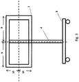
Fig. 3 shows schematically a back view of a transportation device according to the present invention; and -
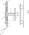
Fig. 4 shows a schematic illustration showing a spring element inside a guide means. -
Fig. 1 shows an example of a facility, wherein said facility comprises a plurality oftransportation devices 40, which are transported along a definedpath 11. Saidpath 11 preferably comprises rails, wherein eachtransportation device 40 preferably has awheel part 8 and wheels of said wheel part are running inside said rails. The facility preferably comprises multiple processing stations for processing theobject 3, in particular TV frame. One station can be acoating station 44, in particular spray painting station, a further station can be a cleaningstation 15 and a further station can be a heating, in particular curing oven, station. - While
conveyor 11 is moving fixture respectivelytransportation device 40 with fixture arrives atspring releasing point 12 while fixture holdsobject 3, in particular TV frame. Preferably a fixed part respectively stationary part, in particularly arranged at a wall or stationary frame, will touch the spring locking device 6. As a result theleft fixing pin 16 and right fixingpin 17 are released fromspring element 20. - After TV frame is painted and cured it's removed from fixture and side rods are fixed to locking position for next process. And it's so simple that doesn't need any sensors, electrical equipment or pneumatic equipment. Present design is a cost saving method avoids producing many different fixtures for all size and group of TV frames. Present design also enables standard spray paint application. This helps system to make flexible design changes for other equipment's like oven, ionization to make system more effective and flexible.
-
Objects 3 are preferably arranged ontransportation devices 40 before saidtransportation devices 40 are entering a cleaningstation 15. After cleaning a spring release means 13 preferably releasesspring element 20, hence a predefined alignment of theobject 3 with respect to main frame 4 results. In a later step a movement ofspring element 20 is preferably reduced or stopped by spring fixing means 12. In a further station 44 a surface processing, in particular coating, takes place, wherein arobot arm 1 preferably guides aprocessing unit 2 along pre-programed paths. In anoven 14 curing of said coating takes place. After curing alltransportation devices 40 carryingobjects 3 are channeled out or allobjects 3 are removed from thesetransportation devices 40. Thus, preferably a continuous conveyor system robot programing for painting is prepared for master TV frame. -
Fig. 2 gives an idea how anobject 3, in particular TV frame, must be hang on a fixture, wherein such a fixture preferably comprises a horizontal positioning means 30 and a vertical positioning means 25. The relative position between anobject 3 and a main frame 4 are preferably fix during transportation and/or processing. Thus, dimensions are preferably stable for all fixtures transported on thecontinuous conveyor 11. Furthermore, an arm-member 42 is provided, wherein said arm-member preferably forms or comprises the vertical positioning means 30. The vertical positioning means 30 preferably comprises vertical coupling means 7 for holding theobject 3 and vertical configuration means 32 for adjusting the vertical position of vertical coupling means 7. It is hereby possible that vertical configuration means 32 enables a stepwise or step less configuration. Arm-member 42 is preferably at least sectionally rotatable or pivotable around a horizontal axis. Arm-member 42 is preferably coupled via aforwarding spring 5 with main frame 4 or horizontal positioning means 25.Spring 5 preferably applies forces onto arm-member in said rotating respectively pivoting direction. The arm-member 42 is preferably inclined respectively pivotable to the vertical direction in an angle between 0° and 90°, in particular in an angle between 2° and 75° or 5° and 60° or 15° and 45°. - For
production robot 1 will follow the same path as it's programmed. To accurate painting application all TV with same dimension and model must be placed on to fixture as it is shown infig. 3 .X 9 andY 10 distances are preferably the same or must be same for all TV frames of the same kind. Thus, the present invention provides a universal fixture for all sizes of TV frames (in particular between 32"-65" or between 20"-150"). -
Fig. 4 shows thatspring element 20 touches the left and right inner side of the TV frames with its fixing rods. Said fixing rods applies forces to contact surfaces of theobject 3, thus the object moves in horizontal direction to bring the forces applied by first rod and second rod in an equilibrium. And it makes it possible to have the same length from side to middle. This mechanical assembly of fixing structure does not affect paint dust, Ionization system blowing air, curing oven temperature and manpower. - The facility and/or one or some or all individual stations, in
particular coating station 44,oven station 14 or cleaningstation 15 or transporting alongpath 11, is/are preferably working without any human control. - To keep
dimensions 9 for horizontal fixing a balancing spring system is located inside the 18 left side fixing rod and 19 right side fixing rod located inside the top fixing rods respectively guide means 21.Spring 20 is preferably designed respectively calculated to force equally to both sides ofTV frame 3 to keep middle point automatically.Spring 20 is preferably coupled in its center with the outer guide means 21. When an operator hangs the TV frame to be painted on to the top fixing rod operator just fixes the vertical positioning fixture respectively vertical configuration means 34. As long as thesame transportation device 40 is used for the kind ofobjects 3, in particular TV frames, preferably no further vertical adjustment of the position of vertical coupling means 7 is required. - Thus, the present invention refers to a fixture, in particular coupled to a
transportation device 40 for transporting of at least oneobject 3, in particular a TV frame, to be coated though a coating facility. The fixture and/or transportation device preferably comprises at least a vertical positioning means 30 for positioning theobject 3 on a predefined height. The fixture and/or transportation device further preferably comprises a horizontal positioning means 25 for positioning theobject 3 in a predefined alignment with respect to the main frame 4. The vertical positioning means 30 preferably comprises a vertical configuration means 32 for adjusting the vertical position of a vertical coupling means 7 and wherein the horizontal positioning means 25 comprises at least two horizontal coupling means 36, 38 for coupling with theobject 3 and a horizontal configuration means 34 for adjusting the distance between the horizontal coupling means 36, 38 in horizontal direction. - Horizontal positioning means 30 preferably describes a positioning means which aligns or arranges the object at least or mainly in horizontal direction. The horizontal positioning means further preferably extends mainly or exclusively in horizontal direction. Vertical positioning means 25 preferably describes a positioning means which aligns or arranges the object at least or mainly in vertical direction. The vertical positioning means further preferably extends mainly or exclusively in vertical direction.
List of reference numbers 1 robot arm / manipulator 16 first locking member / left locking pin 2 processing unit / paint spray gun 3 object / TV frame 17 second locking member / right locking pin 4 main frame 18 left fixing rod 5 forward spring 19 right fixing rod 6 spring locking device / locking control means 20 balancing spring / spring element 7 vertical coupling means 21 guide means / horizontal outer fixing rod 8 continuous conveyor carrier car / wheel part 25 horizontal positioning means 9 horizontal fixing length 30 vertical positioning means 10 vertical fixing length 32 vertical configuration means 11 conveyer unit / continuous conveyor 34 horizontal configuration means 36 first horizontal coupling means 12 spring fixing means / spring fixing sensor 38 second horizontal coupling means 40 transportation device / universal TV fixture 13 spring releasing means / spring releasing sensor 42 arm- member 14 curing oven / paint curing oven 44 coating station 15 cleaning station / ionized TV frame cleaning system
Claims (15)
- Transportation device (40) for transporting of at least one object (3), in particular a TV
frame, to be coated,
at least comprising
a vertical positioning means (30) for positioning the object (3) on a predefined height,
a horizontal positioning means (25) for positioning the object (3) in a predefined alignment with respect to the main frame (4),
wherein the vertical positioning means (30) comprises a vertical configuration means (32) for adjusting the vertical position of a vertical coupling means (7)
and
wherein the horizontal positioning means (25) comprises at least two horizontal coupling means (36, 38) for coupling with the object (3) and a horizontal configuration means (34) for adjusting the distance between the horizontal coupling means (36, 38) in horizontal direction. - Transportation device according to claim 1,
characterized in that
the horizontal positioning means (25) comprises at least one spring element,
wherein at least one horizontal coupling means (18) and preferably both horizontal coupling means (36) are spring loaded by said spring element (20). - Transportation device according to claim 2,
characterized in that
each horizontal coupling means (36, 38) is arranged on a movable rod (18, 19), wherein the movable rod (18, 19) is moveable in horizontal direction, wherein the movable rods (18, 19) are at least sectionally arranged inside a guide means (21) and coupled to said spring element (20). - Transportation device according to claim 3,
characterized in that
at least or exactly two locking members (16, 17) are provided,
wherein the locking members (16,17) are arranged in or on the guide means (21),
wherein one locking member (16) is arranged in a section of guide means (21) in which one rod (18) is arranged,
and
wherein the other locking member (17) is arranged in another section of guide means (21) in which the other rod (19) is arranged,
wherein a relative movement between each rod (18, 19) and guide means (21) can be limited, in particularly prevented. - Transportation device according to claim 4,
characterized in that
a locking control means (6) is provided,
wherein the locking control means (6) comprises mechanical parts for operating the locking members (16,17). - Transportation device according to claim 5,
characterized in that
the locking control means (6) comprises an actuation element for directing mechanical forces to both locking members (16, 17) at the same time. - Transportation device according to any of the before mentioned claims,
characterized in that
the vertical positioning means (30) extends along an arm-member (42),
wherein at least one vertical coupling means (7) for supporting the object (3) in vertical direction is part of an arm-member (42). - Transportation device according to claim 7,
characterized in that
the arm-member (42) comprises a fixing means,
wherein the vertical coupling means (7) is movable in vertical direction and wherein the position of the vertical coupling means (7) is fixable by the fixing means. - Transportation device according to claim 7 or 8,
characterized in that
the arm-member (42) is inclined to the vertical direction in an angle between 2° and 45°, in particular in an angle between 2° and 35° or 5° and 25°. - Transportation device according to any of the before mentioned claims,
characterized in that
a main frame (4) is provided,
wherein the vertical position means (30) and the horizontal positioning means (25) are arranged at the main frame (4). - Transportation device according to any of the before mentioned claims,
characterized in that
a plurality of wheels, in particular at least three wheels, are provided, wherein the wheels are arranged in a lower section of the main frame (4),
wherein the horizontal positioning means (30) is arranged at an upper section of the main frame (4), wherein the upper section is above the lower section. - Facility for coating objects
at least comprising
a multi axis robot arm (1), wherein a coating, in particular spraying, unit is attached to the robot arm (1)
and
multiple transportation devices (40) according to any of the before mentioned claims. - Facility according to claim 12,
characterized in that
a transportation path (11) for transporting the transportation devices (40) is provided, in particular rails,
wherein further handling stations (14,15) are provided along the transportation path (40),
wherein one further handling station is a curing oven (14)
and/or
wherein another handling station is a cleaning station (15) for cleaning the object (3). - Method for processing objects (3),
at least comprising the steps
Providing a transportation device (40) according to any of claims 1 to 11,
Positioning the object (3),
wherein a vertical positioning takes place by means of a vertical positioning means (30) for positioning the object (3) on a predefined height and wherein a horizontal positioning takes place by a horizontal positioning means (25) for positioning the object (3) in a predefined alignment with respect to a main frame (4),
wherein the vertical positioning means (25) comprises a vertical configuration means (32) for adjusting the vertical position of a vertical coupling means (7)
and
wherein the horizontal positioning means (25) comprises at least two horizontal coupling means (36, 38) for coupling with the object (3) and a horizontal configuration means (34) for adjusting the distance between the horizontal coupling means (36, 38) in horizontal direction,
Processing the object (3) with a processing unit,
wherein the stationary robot arm (1) comprises the processing unit (2),
wherein the processing unit (2) is movable by said robot arm (1) with multiple degrees of freedom,
wherein the object (3) is transported by means of the transportation device (40) into a processing region of said robot arm (1). - Method according to claim 14,
characterized in that
the transportation device (40) holding the processed object (3) is moved inside a curing oven (14), wherein the transportation device (40) stays inside the curing oven (14) until the object (3) is processed in the curing oven (14).
Priority Applications (2)
| Application Number | Priority Date | Filing Date | Title |
|---|---|---|---|
| EP17157727.3A EP3366379A1 (en) | 2017-02-23 | 2017-02-23 | Transport device for processing tv frames, facility with processing units for processing tv frames and method for processing tv frames |
| TR2017/03043A TR201703043A2 (en) | 2017-02-23 | 2017-02-28 | Transport device for processing TV frames, facility with processing units for processing TV frames and method for processing TV frames. |
Applications Claiming Priority (1)
| Application Number | Priority Date | Filing Date | Title |
|---|---|---|---|
| EP17157727.3A EP3366379A1 (en) | 2017-02-23 | 2017-02-23 | Transport device for processing tv frames, facility with processing units for processing tv frames and method for processing tv frames |
Publications (1)
| Publication Number | Publication Date |
|---|---|
| EP3366379A1 true EP3366379A1 (en) | 2018-08-29 |
Family
ID=58162488
Family Applications (1)
| Application Number | Title | Priority Date | Filing Date |
|---|---|---|---|
| EP17157727.3A Withdrawn EP3366379A1 (en) | 2017-02-23 | 2017-02-23 | Transport device for processing tv frames, facility with processing units for processing tv frames and method for processing tv frames |
Country Status (2)
| Country | Link |
|---|---|
| EP (1) | EP3366379A1 (en) |
| TR (1) | TR201703043A2 (en) |
Cited By (1)
| Publication number | Priority date | Publication date | Assignee | Title |
|---|---|---|---|---|
| CN110787940A (en) * | 2019-11-29 | 2020-02-14 | 深圳市辉翰科技发展有限公司 | Real-time adjusting spray head for automatic glue sprayer |
Citations (6)
| Publication number | Priority date | Publication date | Assignee | Title |
|---|---|---|---|---|
| US2946584A (en) * | 1958-02-26 | 1960-07-26 | Edwards John Kenneth | Radio and television chassis stand |
| GB2223460A (en) * | 1988-09-28 | 1990-04-11 | Newton Shimpe Raymond Dennis | Trolley |
| EP0646418A1 (en) | 1993-10-05 | 1995-04-05 | Ykk Corporation | Full automatic coating system for coating various types of products produced in small quantities |
| US20080142652A1 (en) * | 2003-05-05 | 2008-06-19 | Innovative Tools & Technologies, Inc. | Mobile paint rack |
| US20120240849A1 (en) * | 2011-03-23 | 2012-09-27 | Deshler Donald T | Painting stand for vehicle body panels |
| US20120276283A1 (en) * | 2011-04-29 | 2012-11-01 | Designs Systems Inc. | Article carrier with non-adherence coating |
-
2017
- 2017-02-23 EP EP17157727.3A patent/EP3366379A1/en not_active Withdrawn
- 2017-02-28 TR TR2017/03043A patent/TR201703043A2/en unknown
Patent Citations (6)
| Publication number | Priority date | Publication date | Assignee | Title |
|---|---|---|---|---|
| US2946584A (en) * | 1958-02-26 | 1960-07-26 | Edwards John Kenneth | Radio and television chassis stand |
| GB2223460A (en) * | 1988-09-28 | 1990-04-11 | Newton Shimpe Raymond Dennis | Trolley |
| EP0646418A1 (en) | 1993-10-05 | 1995-04-05 | Ykk Corporation | Full automatic coating system for coating various types of products produced in small quantities |
| US20080142652A1 (en) * | 2003-05-05 | 2008-06-19 | Innovative Tools & Technologies, Inc. | Mobile paint rack |
| US20120240849A1 (en) * | 2011-03-23 | 2012-09-27 | Deshler Donald T | Painting stand for vehicle body panels |
| US20120276283A1 (en) * | 2011-04-29 | 2012-11-01 | Designs Systems Inc. | Article carrier with non-adherence coating |
Cited By (1)
| Publication number | Priority date | Publication date | Assignee | Title |
|---|---|---|---|---|
| CN110787940A (en) * | 2019-11-29 | 2020-02-14 | 深圳市辉翰科技发展有限公司 | Real-time adjusting spray head for automatic glue sprayer |
Also Published As
| Publication number | Publication date |
|---|---|
| TR201703043A2 (en) | 2018-09-21 |
Similar Documents
| Publication | Publication Date | Title |
|---|---|---|
| US9005715B2 (en) | Method for the surface treatment of large parts, gripper of parts suitable for implementing such a method, use of said gripper and treatment cubicle | |
| CN201157810Y (en) | Robot automatic spraying system for automobile bottom PVC glue | |
| JP6432982B2 (en) | Repainting equipment | |
| CN110314792B (en) | Spraying method of automatic spraying unit for workpiece with long and thin structure | |
| KR102068044B1 (en) | Powder coating system | |
| BR122020014269B1 (en) | STATIONS AND FACILITIES FOR SURFACE TREATMENT OF OBJECTS | |
| RU2552441C2 (en) | Method and device to paint vehicle body part | |
| CN110369206B (en) | Automatic spraying and drying production system for net rack connecting rod | |
| CN108417137A (en) | Industrial robot intelligence real training production line | |
| CN110525029A (en) | Full-automatic pad printer | |
| JP2022501194A (en) | Surface treatment equipment and surface treatment method for surface treatment of the vehicle body | |
| ITUB20159139A1 (en) | PLANT FOR HORIZONTAL PAINTING OF SHAPED DOORS | |
| US20180078968A1 (en) | Apparatus and method for painting three-dimensional objects | |
| CN110237974B (en) | An automatic spraying production line for slender structural workpieces | |
| US10494287B2 (en) | Device for manufacturing hollow glass articles | |
| JP7300947B2 (en) | painting system | |
| Zunaidi | Parameter settings for an automated gantry-robot painting system using a 3-gun atomization spray method for an anti-static coating process | |
| EP3207998B1 (en) | Painting plant and method | |
| CN210700739U (en) | Automatic spraying unit for workpieces with long and thin structures | |
| CN210935595U (en) | Automatic spraying and drying production system for net rack connecting rod | |
| CN111356567A (en) | Apparatus for producing clad plastic components and method therefor | |
| CN218167455U (en) | Automatic spraying production line for flat plate type workpieces | |
| TR201703043A2 (en) | Transport device for processing TV frames, facility with processing units for processing TV frames and method for processing TV frames. | |
| JPH0568916A (en) | Painting equipment | |
| CN205109954U (en) | An automatic spraying production line for car lamp PC mask hardening paint |
Legal Events
| Date | Code | Title | Description |
|---|---|---|---|
| PUAI | Public reference made under article 153(3) epc to a published international application that has entered the european phase |
Free format text: ORIGINAL CODE: 0009012 |
|
| AK | Designated contracting states |
Kind code of ref document: A1 Designated state(s): AL AT BE BG CH CY CZ DE DK EE ES FI FR GB GR HR HU IE IS IT LI LT LU LV MC MK MT NL NO PL PT RO RS SE SI SK SM TR |
|
| AX | Request for extension of the european patent |
Extension state: BA ME |
|
| STAA | Information on the status of an ep patent application or granted ep patent |
Free format text: STATUS: THE APPLICATION IS DEEMED TO BE WITHDRAWN |
|
| 18D | Application deemed to be withdrawn |
Effective date: 20190301 |