EP3366235A2 - Surgical stapling apparatus with staple sheath - Google Patents
Surgical stapling apparatus with staple sheath Download PDFInfo
- Publication number
- EP3366235A2 EP3366235A2 EP18158993.8A EP18158993A EP3366235A2 EP 3366235 A2 EP3366235 A2 EP 3366235A2 EP 18158993 A EP18158993 A EP 18158993A EP 3366235 A2 EP3366235 A2 EP 3366235A2
- Authority
- EP
- European Patent Office
- Prior art keywords
- staple
- assembly
- sheath
- cartridge
- retention slots
- Prior art date
- Legal status (The legal status is an assumption and is not a legal conclusion. Google has not performed a legal analysis and makes no representation as to the accuracy of the status listed.)
- Granted
Links
Images


Classifications
-
- A—HUMAN NECESSITIES
- A61—MEDICAL OR VETERINARY SCIENCE; HYGIENE
- A61B—DIAGNOSIS; SURGERY; IDENTIFICATION
- A61B17/00—Surgical instruments, devices or methods, e.g. tourniquets
- A61B17/11—Surgical instruments, devices or methods, e.g. tourniquets for performing anastomosis; Buttons for anastomosis
- A61B17/115—Staplers for performing anastomosis in a single operation
- A61B17/1155—Circular staplers comprising a plurality of staples
-
- A—HUMAN NECESSITIES
- A61—MEDICAL OR VETERINARY SCIENCE; HYGIENE
- A61B—DIAGNOSIS; SURGERY; IDENTIFICATION
- A61B17/00—Surgical instruments, devices or methods, e.g. tourniquets
- A61B17/068—Surgical staplers, e.g. containing multiple staples or clamps
-
- A—HUMAN NECESSITIES
- A61—MEDICAL OR VETERINARY SCIENCE; HYGIENE
- A61B—DIAGNOSIS; SURGERY; IDENTIFICATION
- A61B46/00—Surgical drapes
- A61B46/10—Surgical drapes specially adapted for instruments, e.g. microscopes
-
- A—HUMAN NECESSITIES
- A61—MEDICAL OR VETERINARY SCIENCE; HYGIENE
- A61B—DIAGNOSIS; SURGERY; IDENTIFICATION
- A61B46/00—Surgical drapes
- A61B46/10—Surgical drapes specially adapted for instruments, e.g. microscopes
- A61B46/13—Surgical drapes specially adapted for instruments, e.g. microscopes the drapes entering the patient's body
-
- A—HUMAN NECESSITIES
- A61—MEDICAL OR VETERINARY SCIENCE; HYGIENE
- A61B—DIAGNOSIS; SURGERY; IDENTIFICATION
- A61B17/00—Surgical instruments, devices or methods, e.g. tourniquets
- A61B17/068—Surgical staplers, e.g. containing multiple staples or clamps
- A61B17/072—Surgical staplers, e.g. containing multiple staples or clamps for applying a row of staples in a single action, e.g. the staples being applied simultaneously
- A61B17/07292—Reinforcements for staple line, e.g. pledgets
-
- A—HUMAN NECESSITIES
- A61—MEDICAL OR VETERINARY SCIENCE; HYGIENE
- A61B—DIAGNOSIS; SURGERY; IDENTIFICATION
- A61B17/00—Surgical instruments, devices or methods, e.g. tourniquets
- A61B2017/00367—Details of actuation of instruments, e.g. relations between pushing buttons, or the like, and activation of the tool, working tip, or the like
- A61B2017/00398—Details of actuation of instruments, e.g. relations between pushing buttons, or the like, and activation of the tool, working tip, or the like using powered actuators, e.g. stepper motors, solenoids
-
- A—HUMAN NECESSITIES
- A61—MEDICAL OR VETERINARY SCIENCE; HYGIENE
- A61B—DIAGNOSIS; SURGERY; IDENTIFICATION
- A61B17/00—Surgical instruments, devices or methods, e.g. tourniquets
- A61B2017/0046—Surgical instruments, devices or methods, e.g. tourniquets with a releasable handle; with handle and operating part separable
- A61B2017/00473—Distal part, e.g. tip or head
-
- A—HUMAN NECESSITIES
- A61—MEDICAL OR VETERINARY SCIENCE; HYGIENE
- A61B—DIAGNOSIS; SURGERY; IDENTIFICATION
- A61B17/00—Surgical instruments, devices or methods, e.g. tourniquets
- A61B17/068—Surgical staplers, e.g. containing multiple staples or clamps
- A61B17/072—Surgical staplers, e.g. containing multiple staples or clamps for applying a row of staples in a single action, e.g. the staples being applied simultaneously
- A61B2017/07214—Stapler heads
- A61B2017/07271—Stapler heads characterised by its cartridge
Definitions
- the present disclosure relates to surgical stapling apparatus for performing endoscopic surgical procedures and methods of use thereof.
- Fasteners e.g., staples or two-part fasteners
- Surgical stapling apparatus employed to apply these fasteners are generally designed to clamp, cut and/or fasten tissue between opposing jaw structure.
- Circular surgical stapling apparatus generally include an annular fastener cartridge assembly that supports annular rows of fasteners in fastener retaining slots, an annular anvil assembly with fastener forming pockets for forming the fasteners of the fastener cartridge upon a firing of the circular surgical stapling apparatus, and an annular blade for cutting tissue.
- These circular surgical stapling apparatus sequentially or simultaneously apply these fasteners to tissue for the purpose of joining segments of tissue together and/or for the creation of anastomoses.
- One challenge associated with anastomosis procedures includes maintaining the integrity of the anastomosis.
- contaminants in proximity to the surgical site could migrate into the fastener retaining slots of the fastener cartridge and contaminate the fasteners supported therein.
- a surgical stapling apparatus includes a first jaw member, staples, a second jaw member and a staple sheath.
- the first jaw member has staple retention slots. Each staple is received in a respective one of the staple retention slots.
- the second jaw member has staple pockets. Each staple pocket is configured to form a respective one of the staples of the plurality of staples as the surgical stapling apparatus is fired.
- the staple sheath is secured to the first jaw member and covers the staple retention slots.
- the staple sheath is movable relative to the first jaw member to uncover the staple retention slots in response to relative approximation of the first jaw member and the second jaw member.
- the staple sheath may be part of a staple sheath assembly including a collar assembly and the staple sheath coupled to the collar assembly.
- the second jaw member may include a head assembly having a center rod assembly extending proximally from the head assembly.
- the center rod assembly may be selectively engagable with the collar assembly to move the staple sheath relative to the first jaw member to uncover the plurality of staple retention slots in response to relative approximation of the first jaw member and the second jaw member.
- the collar assembly may include one or more spokes and the first jaw member may define one or more elongated channels that extend axially along the first jaw member.
- the one or more spokes may be slidably movable through the one or more elongated channels to enable the staple sheath to move relative to the first jaw member.
- the first jaw member may include a staple cartridge.
- the staple cartridge may define an annular groove configured to receive a distal end portion of the staple sheath assembly to selectively secure the staple sheath across the staple cartridge covering the staple retention slots while the first and second jaw members are unapproximated.
- the surgical stapling apparatus further includes an elongated shaft assembly that extends from a proximal end portion to a distal end portion.
- the first jaw member and the staple sheath assembly may be removably secured to the distal end portion of the elongated shaft assembly.
- an end effector for a surgical stapling apparatus includes a cartridge assembly, staples, an anvil assembly, and a staple sheath.
- the cartridge assembly has staple retention slots. Each staple is received in a respective one of the staple retention slots.
- the anvil assembly has staple pockets. Each staple pocket is configured to form a respective one of the staples as the surgical stapling apparatus is fired.
- the anvil assembly is movable relative to the cartridge assembly between an unapproximated position and an approximated position.
- the staple sheath is secured to the cartridge assembly and positioned to cover the staple retention slots.
- the staple sheath is movable with the anvil assembly to uncover the plurality of staple retention slots and expose the plurality of staples.
- the anvil assembly may include a head assembly and a center rod assembly that extends from the head assembly.
- the center rod assembly may be selectively engagable with the collar assembly to move the staple sheath relative to the cartridge assembly upon a movement of the anvil assembly relative to the cartridge assembly.
- the collar assembly may include one or more spokes and the cartridge assembly defines one or more elongated channels extending axially along the cartridge assembly.
- the one or more spokes may be slidably movable through the one or more elongated channels to enable the staple sheath to move relative to the cartridge assembly.
- the cartridge assembly may include a staple cartridge defining an annular groove configured to receive a distal end portion of the staple sheath assembly to selectively secure the staple sheath in a position to cover the plurality of staple retention slots while the anvil and cartridge assemblies are in the unapproximated position.
- the end effector further includes an elongated shaft assembly that extends from a proximal end portion to a distal end portion.
- the cartridge assembly and the staple sheath assembly may be removably secured to the distal end portion of the elongated shaft assembly.
- a circular stapling apparatus includes an elongated shaft assembly, a cartridge assembly, staples, a collar assembly, and a staple sheath.
- the elongated shaft assembly has a distal end portion and defining a longitudinal axis.
- the cartridge assembly is secured to the distal end portion of the elongated shaft assembly and has a tissue contact surface.
- the tissue contact surface defines staple retention slots. Each staple is received in a respective one of the staple retention slots.
- the collar assembly is movable along the longitudinal axis between a distal position and a proximal position.
- the staple sheath is coupled to the collar assembly and positioned to cover the plurality of staple retention slots while the collar assembly is in the distal position.
- the staple sheath is movable with the collar assembly toward the proximal position to draw the staple sheath across the plurality of staple retention slots.
- the collar assembly may include one or more spokes and the cartridge assembly may define one or more elongated channels extending axially along the cartridge assembly.
- the one or more spokes may be slidably movable through the one or more elongated channels to enable the staple sheath to move relative to the cartridge assembly.
- the cartridge assembly may include a staple cartridge defining an annular groove configured to receive a distal end portion of the staple sheath to selectively secure the staple sheath in a position to cover the staple retention slots.
- the cartridge assembly and the staple sheath assembly may be selectively removable from the distal end portion of the elongated shaft assembly.
- the circular stapling apparatus may further include an anvil assembly selectively coupled to the elongated shaft assembly.
- the anvil assembly may be movable relative to the cartridge assembly to move the collar assembly from the distal position to the proximal position.
- a cartridge assembly for selective connection to a surgical stapling apparatus.
- the cartridge assembly includes a body portion, a tissue contact surface, staples, a collar assembly, and a staple sheath.
- the tissue contact surface defines staple retention slots. Each staple is received in a respective one of the staple retention slots.
- the collar assembly is movably mounted to the body portion.
- the staple sheath is coupled to the collar assembly and positioned to cover the staple retention slots. The staple sheath is selectively movable relative to the tissue contact surface.
- the body portion defines one or more elongated channels.
- the collar assembly may include one or more spokes slidably movable through the one or more elongated channels to enable the staple sheath to move relative to the body portion.
- the cartridge assembly further includes a staple cartridge coupled to the body portion.
- the staple cartridge may include the tissue contact surface and may support the staples.
- the staple cartridge may define an annular groove configured to receive a distal end portion of the staple sheath to selectively secure the staple sheath across the tissue contact surface of the staple cartridge.
- the collar assembly may be is selectively movable between distal and proximal positions relative to the body portion to move the staple sheath relative to the tissue contact surface.
- distal refers to that portion of the apparatus, and/or component thereof, farther from the user
- proximal refers to that portion of the apparatus, and/or component thereof, closer to the user
- physician refers to a doctor, nurse, or other care provider and may include support personnel.
- an electromechanical surgical stapling system or apparatus defines a centerline "CL" and includes a surgical device 100 in the form of a powered handheld electromechanical instrument.
- the electromechanical surgical stapling system 10 further includes an adapter assembly 200 that is selectively attachable to the surgical device 100.
- the adapter assembly 200 extends distally from the surgical device 100 and has an elongated body 202 that extends to a distal end.
- the distal end of the elongated body 202 supports an end effector 300.
- the end effector 300 includes a shell or cartridge assembly 310 and an anvil assembly 320 that are positionable between an unclamped or unapproximated position (see FIG.
- the surgical device 100 is configured for selective connection with the adapter assembly 200, and, in turn, the adapter assembly 200 is configured for selective connection with the end effector 300. Together, the surgical device 100 and the adapter assembly 200 cooperate to operate the end effector 300.
- the surgical device 100 of the electromechanical surgical stapling system 10 includes a handle housing 102 that defines a cavity "C" for selective removable receipt of a rechargeable battery 103.
- the battery 103 is configured to supply power to electrical components of the surgical device 100.
- the cavity "C” supports a controller or circuit board 105 configured to control various operations of the surgical device 100.
- the electromechanical surgical stapling system 10 further includes a drive mechanism 106 configured to drive rotatable shafts and/or gear components (not shown) within the handle housing 102 in order to perform various operations of the electromechanical surgical stapling system 10.
- the drive mechanism 106 may be operable to selectively rotate the end effector 300 about, and/or relative to, the centerline "CL" of the electromechanical surgical stapling system 10; to selectively move the anvil assembly 320 relative to the cartridge assembly 310 to selectively clamp tissue; and/or to fire the electromechanical surgical stapling system 10 for fastening and/or cutting the clamped tissue.
- the battery 103, controller 105, and/or drive mechanism 106 may be operably coupled to one or more triggers 107a, 107b such as finger-actuated control buttons, rocker devices, and/or the like to effectuate various functions of the electromechanical surgical stapling system 10 such as those described above.
- triggers 107a, 107b such as finger-actuated control buttons, rocker devices, and/or the like to effectuate various functions of the electromechanical surgical stapling system 10 such as those described above.
- the drive mechanism 106 of the electromechanical surgical stapling system 10 includes an approximation mechanism 108 that extends distally through the elongated body 202 and includes an anvil retainer 108a ( FIG. 9 ) supported on a distal end portion of the approximation mechanism 108.
- the anvil retainer 108a is configured to move along the centerline "CL" of the electromechanical surgical stapling system 10 between distal and proximal positions to selectively or removably couple to the anvil assembly 320 as described in U.S. Patent No. 7,303,106 , the entire contents of which are incorporated by reference herein.
- the anvil retainer 108a is also configured to move along the centerline "CL" of the electromechanical surgical stapling system 10 between the distal and proximal positions of the anvil retainer 108a to move the anvil assembly 320 between the approximated and unapproximated positions relative to the cartridge assembly 310 to selectively clamp and/or unclamp tissue.
- the surgical stapling apparatus is described as an electromechanically powered surgical stapling apparatus
- the presently disclosed surgical stapling apparatus can be provided as a manually powered stapling apparatus.
- U.S. Patent No. 8,272,552, filed January 30, 2012 the entire contents of which are incorporated by reference herein (see also U.S. Patent No. 7,303,106 incorporated herein by reference above).
- the cartridge assembly 310 of the end effector 300 includes a shell 312, a pusher 313, a cylindrical knife 314, a staple cartridge 315, and a staple sheath assembly 316.
- the shell 312 of the cartridge assembly 310 is secured to a distal end of the elongated body 202 of the adapter assembly 200 and includes an outer housing portion 312a configured to selectively receive the staple cartridge 315, an inner guide portion 312b configured to selectively receive the anvil assembly 320 of the end effector 300, and a coupling portion 312x configured to couple the cartridge assembly 310 to the elongated body 202 of the adapter assembly 200.
- the coupling portion 312x includes a proximal portion 3122, a distal portion 3124, and a flange 3126 that separates the proximal and distal portions 3122, 3124.
- the outer housing portion 312a defines elongated slots 312c at radially spaced locations around the shell 312 and which are configured to slidably support the staple sheath assembly 316.
- the outer housing portion 312a includes a housing collar assembly 312d configured to facilitate selective attachment of the cartridge assembly 310 to the elongated body 202 similar to that described in U.S. Patent Application Publication No. 2016/0192934, filed October 19, 2015 , the entire contents of which are incorporated by reference herein.
- the pusher 313 of the cartridge assembly 310 is slidably positioned about the inner guide portion 312b of the shell 312 and defines a central throughbore 313a.
- the pusher 313 includes annular arrays of distally extending fingers 313b configured to support an array of staples 317.
- One or more of the fingers 313b and/or one or more of the staples 317 may include different heights. In some embodiments, one or more of the fingers 313b and/or one or more of the staples 317 may include the same height.
- the cylindrical knife 314 of the cartridge assembly 310 is frictionally retained within the central throughbore 313a of the pusher 313 to fixedly secure the knife 314 in relation to the pusher 313.
- the distal end of the knife 314 includes a circular cutting edge 314a configured to severe tissue.
- the staple cartridge 315 of the cartridge assembly 310 includes a tissue contact surface 315a in which annular arrays of slots 315b are formed.
- the annular arrays of slots 315b of the staple cartridge 315 are configured to support and slidably receive the annular arrays of staples 317 therein.
- the staple cartridge 315 includes an inner surface 315c and an outer surface 315d.
- the inner surface 315c defines a groove 315e therein.
- the groove 315e of the inner surface 315c of the staple cartridge 315 may have an annular configuration.
- the staple sheath assembly 316 of the cartridge assembly 310 includes a collar assembly 316a coupled to a staple sheath 316b.
- the staple sheath 316b of the staple sheath assembly 316 includes a proximal end portion 3162, a distal end portion 3164, and an opening 3166 defined through the proximal and distal end portions 3162, 3164 of the staple sheath 316b.
- the staple sheath 316b further includes an outer surface 3167 and an inner surface 3168.
- the proximal end portion 3162 of the staple sheath 316b is secured to the collar assembly 316a and the distal end portion 3164 of the staple sheath 316b is receivable within the groove 315e of the staple cartridge 315 to selectively or removably secure the distal end portion 3164 of the staple sheath 316b to the staple cartridge 315.
- the distal end portion 3164 of the staple sheath 316b may be folded over the tissue contact surface 315a of the staple cartridge 315 and/or folded into the groove 315e of the staple cartridge 315.
- the staple sheath 316b is configured to cover the tissue contact surface 315a, annular arrays of slots 315b, and annular arrays of staples 317 of the staple cartridge 315 while the distal end portion 3164 is secured to the groove 315e of the staple cartridge 315 to protect and maintain sterility of the staple cartridge 315 and staples 317.
- the staple sheath 316b is also configured to move relative to the staple cartridge 315 to separate the staple sheath 316b from the groove 315e and slide along the tissue contact surface 315a of the staple cartridge 315.
- the staple sheath 316b, or portions thereof can be configured to be drawn across the staple cartridge 315 to expose the tissue contact surface 315a and the staples 317. In certain embodiments, the staple sheath 316b can be configured to be drawn partially across the tissue contact surface 315a of the staple cartridge 315. In some embodiments, the staple sheath 316, or portions thereof, may be configured to act as buttress material that remains coupled to the staple cartridge 315 until secured to tissue with the staples 317 upon a firing of the staples 317 from the staple cartridge 315.
- the distal end portion 3164 of the staple sheath 316b may be separated from the groove 315e of the staple cartridge 315 and drawn across the tissue contact surface 315a such that the distal end portion 3164 covers the tissue contact surface 315a and acts as a buttress material for use with the staples 317.
- the distal end portion 3164 of the staple sheath 316 is configured to remain fixed to the groove 315e of the staple cartridge 315 such that movement of the staple sheath 316b relative to the staple cartridge 315 causes the staple sheath 316b to tear, dividing the staple sheath 316b into separate portions.
- the staple sheath 316, or portions thereof may include perforations (e.g., an annular ring of perforations, not shown) or the like, to enable portions of the staple sheath 316 to separate from one another upon an application of separating force thereto.
- the staple sheath 316, or portions thereof may be formed in bands, layers, and/or combinations thereof.
- the staple sheath 316b, or portions thereof, may be formed of any suitable polymeric material.
- the polymeric material may be flexible.
- the staple sheath 316b may include multiple materials.
- the staple sheath 316b, or portions thereof, may include biocompatible and/or biodegradable material.
- the staple sheath 316b may include biologically acceptable additives such as plasticizers, antioxidants, dyes, dilutants, therapeutic agents, and the like, and/or combinations thereof, which can be coated thereon, and/or impregnated therein (e.g., during formation).
- suitable materials and/or additives for use with the staple sheath of the present disclosure reference can be made to U.S. Patent No. 8,453,910 , the entire contents of which are incorporated by reference herein.
- the collar assembly 316a of the staple sheath assembly 316 includes a first or proximal collar 318 coupled to a second or distal collar 319.
- the proximal collar 318 of the collar assembly 316a includes an outer member 318a, an inner member 318b coupled to the outer member 318a, and an annular flange 318c extending radially outward from a distal end of the outer member 318a to couple the proximal and distal collars 318, 319 together.
- An inner surface of the outer member 318a and an outer surface of the inner member 318b define an annular trough channel 318d configured to slidably receive a proximal portion of the coupling portion 312x of the shell 312.
- the distal collar 319 of the collar assembly 316a includes spokes 319a.
- the spokes 319a are annularly or radially spaced apart at predetermined arc lengths.
- the spokes 319a have a collar coupling portion 319b at a proximal end portion thereof that couple to the annular flange 318c of the proximal collar 318 and a ring coupling portion 319c that couple to a ring member 319e at a distal end portion thereof.
- Each of the spokes 319a includes a first arm 319f, a second arm 319g, and a third arm 319h that are coupled together and disposed at different angles relative to one another.
- the first and third arms 319f, 319h may be disposed transverse or even perpendicular relative to one another.
- the ring member 319e of the distal collar 319 is secured to the proximal end portion 3162 of the staple sheath 316b using any suitable securement technique such as adhesive, welding, fastening, etc.
- the ring member 319e may be secured to the inner surface 3168 of the staple sheath 316b.
- the anvil assembly 320 of the end effector 300 includes an anvil head assembly 322 and an anvil center rod assembly 324.
- the anvil head assembly 322 includes a post 325, an anvil head 326, and an anvil 327.
- the anvil 327 of the anvil head assembly 322 is supported on the anvil head 326 of the anvil head assembly 322 and includes a tissue contact surface 327a that defines annular arrays of staple forming pockets 327b arranged to correspond to the annular arrays of slots 315b formed in the staple cartridge 315 of the end effector 300.
- the annular arrays of pockets 327b of the anvil 317 are arranged to receive and form the staples 317 of the end effector 300 when that staples 317 are ejected or fired from the slots 315b of the staple cartridge 315.
- the anvil center rod assembly 324 includes an anvil center rod 324a that defines a bore 324b and has flexible arms 324c, 324d, and 324e.
- the anvil retainer 108a of the approximation mechanism 108 of the electromechanical surgical stapling system 10 is received within the central bore 324b of the anvil center rod 324a such that the flexible or resilient radial arms 324c, 324d, 324e releasably engage the anvil retainer 108a of the approximation mechanism 108 and selectively couple the anvil retainer 108a to the center rod 324a of the anvil assembly 320.
- a pivot member or pin 328 secures the anvil head assembly 322 to the post 325 to enable the anvil head assembly 322 to pivot relative to the post 325, about the pivot member 328.
- the staple sheath 316b of the staple sheath assembly 316 is secured to the staple cartridge 315 so that the staple sheath 316b covers the staple cartridge 315 ( FIGS. 9 and 11 ).
- the flexible arms 324c, 324d, 324e of the anvil assembly 320 are longitudinally spaced from the inner member 318b of the proximal collar 318 and the proximal portion 3122 of the coupling portion 312x of the cartridge assembly 310 is fully seated in the annular trough channel 318d of the proximal collar 318 of the staple sheath assembly 316 such that flange 318c of the proximal collar 318 of the staple sheath assembly 316 and the flange 3126 of the coupling portion 312x are engaged ( FIG. 10 ).
- the end effector 300 can be advanced to a surgical site with the staples 317 and/or the tissue contact surface 315a of the staple cartridge 315 protected from potential contaminants that could affect sterility of the staples 317 and/or the tissue contact surface 315a of the staple cartridge 315 during advancement to the surgical site ( FIG. 11 ).
- the anvil assembly 320 of the end effector 300 can be approximated toward the cartridge assembly 310 of the end effector 300, as indicated by arrows "A" ( FIG. 12 ).
- the flexible arms 324c, 324d, 324e of the anvil center rod assembly 324 engage the distal end of the inner member 318b of the proximal collar 318 of the staple sheath assembly 316 and advance or translate the staple sheath assembly 316 proximally, as indicated by arrows "B" ( FIGS. 12 and 13 ).
- proximal advancement of the staple sheath assembly 316 causes the proximal collar 318 thereof to slide along the coupling portion 312x of the cartridge assembly 310 relative to the centerline "CL" of the electromechanical surgical stapling system 10 ( FIG. 1 ) and causes the staple sheath 316b of the staple sheath assembly 316 to separate from the staple cartridge 315.
- the staple sheath assembly 316 moves proximally, the staple sheath 316b thereof draws across the staple cartridge 315, as indicated by arrows "D" ( FIG.
- the staple sheath 316b, or portions thereof can be configured to enable the staples 317 to be fired therethrough (e.g., such as where the staple sheath 316b, or portions thereof, act as buttress material as described above).
- the anvil assembly 320 of the end effector 300 can then be unapproximated or separated from the cartridge assembly 310 of the end effector 300 to release the stapled tissue and remove the end effector 300 from the surgical site.
- the anvil and/or cartridge assemblies 310, 320 can be removed from the electromechanical surgical stapling system 10 and/or replaced as described in U.S. Patent No. 7,303,106 and/or U.S. Patent Application Publication No. 2016/0192934 , each of which are incorporated herein by reference above.
- securement of any of the components of the presently disclosed devices can be effectuated using known securement techniques such welding, crimping, gluing, fastening, etc.
- the various embodiments disclosed herein may also be configured to work with robotic surgical systems and what is commonly referred to as "Telesurgery.”
- Such systems employ various robotic elements to assist the clinician and allow remote operation (or partial remote operation) of surgical instrumentation.
- Various robotic arms, gears, cams, pulleys, electric and mechanical motors, etc. may be employed for this purpose and may be designed with a robotic surgical system to assist the clinician during the course of an operation or treatment.
- Such robotic systems may include remotely steerable systems, automatically flexible surgical systems, remotely flexible surgical systems, remotely articulating surgical systems, wireless surgical systems, modular or selectively configurable remotely operated surgical systems, etc.
- the robotic surgical systems may be employed with one or more consoles that are next to the operating theater or located in a remote location.
- one team of clinicians may prep the patient for surgery and configure the robotic surgical system with one or more of the instruments disclosed herein while another clinician (or group of clinicians) remotely control the instruments via the robotic surgical system.
- a highly skilled clinician may perform multiple operations in multiple locations without leaving his/her remote console which can be both economically advantageous and a benefit to the patient or a series of patients.
- U.S. Patent Application Publication No. 2012/0116416 and PCT Application Publication No. WO2016/025132 , the entire contents of each of which are incorporated by reference herein.
Abstract
Description
- This application claims the benefit of and priority to
U.S. Provisional Patent Application Serial No. 62/464,627 filed February 28, 2017 - The present disclosure relates to surgical stapling apparatus for performing endoscopic surgical procedures and methods of use thereof.
- Fasteners, e.g., staples or two-part fasteners, have traditionally been used to replace suturing when joining various body structures such as the bowel or bronchus, for instance. Surgical stapling apparatus employed to apply these fasteners are generally designed to clamp, cut and/or fasten tissue between opposing jaw structure. Circular surgical stapling apparatus, for example, generally include an annular fastener cartridge assembly that supports annular rows of fasteners in fastener retaining slots, an annular anvil assembly with fastener forming pockets for forming the fasteners of the fastener cartridge upon a firing of the circular surgical stapling apparatus, and an annular blade for cutting tissue. These circular surgical stapling apparatus sequentially or simultaneously apply these fasteners to tissue for the purpose of joining segments of tissue together and/or for the creation of anastomoses.
- One challenge associated with anastomosis procedures includes maintaining the integrity of the anastomosis. During instrument insertion into a surgical site, there is a risk that contaminants in proximity to the surgical site could migrate into the fastener retaining slots of the fastener cartridge and contaminate the fasteners supported therein.
- Accordingly, it would be advantageous to provide a surgical stapling apparatus that prevents fastener contamination for improving the integrity of an anastomosis.
- According to an aspect of the present disclosure, a surgical stapling apparatus is provided. The surgical stapling apparatus includes a first jaw member, staples, a second jaw member and a staple sheath. The first jaw member has staple retention slots. Each staple is received in a respective one of the staple retention slots. The second jaw member has staple pockets. Each staple pocket is configured to form a respective one of the staples of the plurality of staples as the surgical stapling apparatus is fired. The staple sheath is secured to the first jaw member and covers the staple retention slots. The staple sheath is movable relative to the first jaw member to uncover the staple retention slots in response to relative approximation of the first jaw member and the second jaw member.
- In some embodiments, the staple sheath may be part of a staple sheath assembly including a collar assembly and the staple sheath coupled to the collar assembly.
- In embodiments, the second jaw member may include a head assembly having a center rod assembly extending proximally from the head assembly. The center rod assembly may be selectively engagable with the collar assembly to move the staple sheath relative to the first jaw member to uncover the plurality of staple retention slots in response to relative approximation of the first jaw member and the second jaw member.
- In some embodiments, the collar assembly may include one or more spokes and the first jaw member may define one or more elongated channels that extend axially along the first jaw member. The one or more spokes may be slidably movable through the one or more elongated channels to enable the staple sheath to move relative to the first jaw member.
- In certain embodiments, the first jaw member may include a staple cartridge. The staple cartridge may define an annular groove configured to receive a distal end portion of the staple sheath assembly to selectively secure the staple sheath across the staple cartridge covering the staple retention slots while the first and second jaw members are unapproximated.
- In some embodiments, the surgical stapling apparatus further includes an elongated shaft assembly that extends from a proximal end portion to a distal end portion. The first jaw member and the staple sheath assembly may be removably secured to the distal end portion of the elongated shaft assembly.
- According to another aspect of the present disclosure, an end effector for a surgical stapling apparatus is provided. The end effector includes a cartridge assembly, staples, an anvil assembly, and a staple sheath. The cartridge assembly has staple retention slots. Each staple is received in a respective one of the staple retention slots. The anvil assembly has staple pockets. Each staple pocket is configured to form a respective one of the staples as the surgical stapling apparatus is fired. The anvil assembly is movable relative to the cartridge assembly between an unapproximated position and an approximated position. The staple sheath is secured to the cartridge assembly and positioned to cover the staple retention slots. The staple sheath is movable with the anvil assembly to uncover the plurality of staple retention slots and expose the plurality of staples.
- In certain embodiments, the anvil assembly may include a head assembly and a center rod assembly that extends from the head assembly. The center rod assembly may be selectively engagable with the collar assembly to move the staple sheath relative to the cartridge assembly upon a movement of the anvil assembly relative to the cartridge assembly.
- In embodiments, the collar assembly may include one or more spokes and the cartridge assembly defines one or more elongated channels extending axially along the cartridge assembly. The one or more spokes may be slidably movable through the one or more elongated channels to enable the staple sheath to move relative to the cartridge assembly.
- In some embodiments, the cartridge assembly may include a staple cartridge defining an annular groove configured to receive a distal end portion of the staple sheath assembly to selectively secure the staple sheath in a position to cover the plurality of staple retention slots while the anvil and cartridge assemblies are in the unapproximated position.
- In certain embodiments, the end effector further includes an elongated shaft assembly that extends from a proximal end portion to a distal end portion. The cartridge assembly and the staple sheath assembly may be removably secured to the distal end portion of the elongated shaft assembly.
- According to yet another aspect of the present disclosure, a circular stapling apparatus is provided. The circular stapling apparatus includes an elongated shaft assembly, a cartridge assembly, staples, a collar assembly, and a staple sheath. The elongated shaft assembly has a distal end portion and defining a longitudinal axis. The cartridge assembly is secured to the distal end portion of the elongated shaft assembly and has a tissue contact surface. The tissue contact surface defines staple retention slots. Each staple is received in a respective one of the staple retention slots. The collar assembly is movable along the longitudinal axis between a distal position and a proximal position. The staple sheath is coupled to the collar assembly and positioned to cover the plurality of staple retention slots while the collar assembly is in the distal position. The staple sheath is movable with the collar assembly toward the proximal position to draw the staple sheath across the plurality of staple retention slots.
- In some embodiments, the collar assembly may include one or more spokes and the cartridge assembly may define one or more elongated channels extending axially along the cartridge assembly. The one or more spokes may be slidably movable through the one or more elongated channels to enable the staple sheath to move relative to the cartridge assembly.
- In certain embodiments, the cartridge assembly may include a staple cartridge defining an annular groove configured to receive a distal end portion of the staple sheath to selectively secure the staple sheath in a position to cover the staple retention slots.
- In some embodiments, the cartridge assembly and the staple sheath assembly may be selectively removable from the distal end portion of the elongated shaft assembly.
- In embodiments, the circular stapling apparatus may further include an anvil assembly selectively coupled to the elongated shaft assembly. The anvil assembly may be movable relative to the cartridge assembly to move the collar assembly from the distal position to the proximal position.
- According to still another aspect of the present disclosure, a cartridge assembly for selective connection to a surgical stapling apparatus is provided. The cartridge assembly includes a body portion, a tissue contact surface, staples, a collar assembly, and a staple sheath. The tissue contact surface defines staple retention slots. Each staple is received in a respective one of the staple retention slots. The collar assembly is movably mounted to the body portion. The staple sheath is coupled to the collar assembly and positioned to cover the staple retention slots. The staple sheath is selectively movable relative to the tissue contact surface.
- In some embodiments, the body portion defines one or more elongated channels. The collar assembly may include one or more spokes slidably movable through the one or more elongated channels to enable the staple sheath to move relative to the body portion.
- In certain embodiments, the cartridge assembly further includes a staple cartridge coupled to the body portion. The staple cartridge may include the tissue contact surface and may support the staples. The staple cartridge may define an annular groove configured to receive a distal end portion of the staple sheath to selectively secure the staple sheath across the tissue contact surface of the staple cartridge.
- In embodiments, the collar assembly may be is selectively movable between distal and proximal positions relative to the body portion to move the staple sheath relative to the tissue contact surface.
- Other aspects, features, and advantages will be apparent from the description, the drawings, and the claims that follow.
- The accompanying drawings, which are incorporated in and constitute a part of this specification, illustrate embodiments of the disclosure and, together with a general description of the disclosure given above, and the detailed description of the embodiment(s) given below, serve to explain the principles of the disclosure, wherein:
-
FIG. 1 is a perspective view of a surgical stapling apparatus in accordance with the principles of the present disclosure; -
FIG. 2 is an enlarged, perspective view of an end effector of the surgical stapling apparatus ofFIG. 1 with an anvil assembly of the end effector shown unapproximated from a cartridge assembly of the end effector; -
FIG. 3 is a perspective view of the cartridge assembly ofFIG. 2 with a staple sheath assembly of the cartridge assembly shown in a first position; -
FIG. 4 is cross-sectional view of the cartridge assembly ofFIG. 3 as taken along section line 4-4 ofFIG. 3 ; -
FIG. 5 is a perspective view of the staple sheath assembly shown inFIG. 3 ; -
FIG. 6 is a cross-sectional view of the staple sheath assembly ofFIG. 5 as taken along section line 6-6 ofFIG. 5 ; -
FIG. 7 is a perspective view of the anvil assembly of the end effector ofFIG. 2 ; -
FIG. 8 is an enlarged, perspective view of the indicated area of detail shown inFIG. 7 ; -
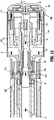
FIG. 9 is a cross-sectional view of the end effector ofFIG. 2 as taken along section line 8-8 shown inFIG. 2 ; -
FIGS. 10 and 11 are enlarged, cross-sectional views of the indicated areas of detail shown inFIG. 9 , respectively; -
FIG. 12 is a cross-sectional view of the end effector ofFIG. 2 as taken along line 8-8 shown inFIG. 2 with the anvil and cartridge assemblies of the end effector shown approximated and with the staple sheath assembly of the cartridge assembly shown in a second position; and -
FIGS. 13 and 14 are enlarged, cross-sectional views of the indicated areas of detail shown inFIG. 12 , respectively. - Embodiments of the presently disclosed surgical stapling apparatus are described in detail with reference to the drawings, in which like reference numerals designate identical or corresponding elements in each of the several views. As used herein, the term "distal" refers to that portion of the apparatus, and/or component thereof, farther from the user, while the term "proximal" refers to that portion of the apparatus, and/or component thereof, closer to the user. As used herein, the term "clinician" refers to a doctor, nurse, or other care provider and may include support personnel. In the following description, well-known functions or constructions are not described in detail to avoid obscuring the present disclosure in unnecessary detail.
- Turning now to
FIGS. 1 and2 , an electromechanical surgical stapling system or apparatus, generally referred to as 10, defines a centerline "CL" and includes asurgical device 100 in the form of a powered handheld electromechanical instrument. The electromechanicalsurgical stapling system 10 further includes anadapter assembly 200 that is selectively attachable to thesurgical device 100. Theadapter assembly 200 extends distally from thesurgical device 100 and has anelongated body 202 that extends to a distal end. The distal end of theelongated body 202 supports anend effector 300. Theend effector 300 includes a shell orcartridge assembly 310 and ananvil assembly 320 that are positionable between an unclamped or unapproximated position (seeFIG. 1 ) and a clamped or approximated position (seeFIG. 12 ) to selectively clamp tissue (not shown) for cutting and/or stapling the tissue. Thesurgical device 100 is configured for selective connection with theadapter assembly 200, and, in turn, theadapter assembly 200 is configured for selective connection with theend effector 300. Together, thesurgical device 100 and theadapter assembly 200 cooperate to operate theend effector 300. - In some embodiments, the
surgical device 100 of the electromechanicalsurgical stapling system 10 includes a handle housing 102 that defines a cavity "C" for selective removable receipt of arechargeable battery 103. Thebattery 103 is configured to supply power to electrical components of thesurgical device 100. The cavity "C" supports a controller orcircuit board 105 configured to control various operations of thesurgical device 100. - The electromechanical
surgical stapling system 10 further includes adrive mechanism 106 configured to drive rotatable shafts and/or gear components (not shown) within the handle housing 102 in order to perform various operations of the electromechanicalsurgical stapling system 10. For instance, thedrive mechanism 106 may be operable to selectively rotate theend effector 300 about, and/or relative to, the centerline "CL" of the electromechanicalsurgical stapling system 10; to selectively move theanvil assembly 320 relative to thecartridge assembly 310 to selectively clamp tissue; and/or to fire the electromechanicalsurgical stapling system 10 for fastening and/or cutting the clamped tissue. Thebattery 103,controller 105, and/or drivemechanism 106 may be operably coupled to one ormore triggers surgical stapling system 10 such as those described above. - The
drive mechanism 106 of the electromechanicalsurgical stapling system 10 includes anapproximation mechanism 108 that extends distally through theelongated body 202 and includes ananvil retainer 108a (FIG. 9 ) supported on a distal end portion of theapproximation mechanism 108. Theanvil retainer 108a is configured to move along the centerline "CL" of the electromechanicalsurgical stapling system 10 between distal and proximal positions to selectively or removably couple to theanvil assembly 320 as described inU.S. Patent No. 7,303,106 , the entire contents of which are incorporated by reference herein. Theanvil retainer 108a is also configured to move along the centerline "CL" of the electromechanicalsurgical stapling system 10 between the distal and proximal positions of theanvil retainer 108a to move theanvil assembly 320 between the approximated and unapproximated positions relative to thecartridge assembly 310 to selectively clamp and/or unclamp tissue. - Reference may be made to International Application No.
PCT/US2008/077249, filed September 22, 2008 (Inter. Pub. No.WO 2009/039506 ),U.S. Patent Application 2015/0157320, filed November 21, 2014 , andU.S. Patent Application Publication No. 2011/0121049, filed on November 20, 2009 , the entire contents of each of which are incorporated herein by reference, for a detailed description of the construction and operation of various exemplary electromechanical surgical systems, the components of which are combinable and/or interchangeable with one or more components of electromechanicalsurgical systems 10 described herein. - Although the surgical stapling apparatus is described as an electromechanically powered surgical stapling apparatus, the presently disclosed surgical stapling apparatus can be provided as a manually powered stapling apparatus. For a more detailed description of the construction and operation of an exemplary manually powered stapling apparatus, one or more components of which can be combined and/or interchanged with the electromechanically powered stapling apparatus described herein, reference can be made to
U.S. Patent No. 8,272,552, filed January 30, 2012 , the entire contents of which are incorporated by reference herein (see alsoU.S. Patent No. 7,303,106 incorporated herein by reference above). - Turning now to
FIGS. 3 and4 , thecartridge assembly 310 of theend effector 300 includes ashell 312, apusher 313, acylindrical knife 314, astaple cartridge 315, and astaple sheath assembly 316. - The
shell 312 of thecartridge assembly 310 is secured to a distal end of theelongated body 202 of theadapter assembly 200 and includes anouter housing portion 312a configured to selectively receive thestaple cartridge 315, aninner guide portion 312b configured to selectively receive theanvil assembly 320 of theend effector 300, and acoupling portion 312x configured to couple thecartridge assembly 310 to theelongated body 202 of theadapter assembly 200. Thecoupling portion 312x includes aproximal portion 3122, adistal portion 3124, and aflange 3126 that separates the proximal anddistal portions outer housing portion 312a defineselongated slots 312c at radially spaced locations around theshell 312 and which are configured to slidably support thestaple sheath assembly 316. Theouter housing portion 312a includes ahousing collar assembly 312d configured to facilitate selective attachment of thecartridge assembly 310 to theelongated body 202 similar to that described inU.S. Patent Application Publication No. 2016/0192934, filed October 19, 2015 , the entire contents of which are incorporated by reference herein. - The
pusher 313 of thecartridge assembly 310 is slidably positioned about theinner guide portion 312b of theshell 312 and defines a central throughbore 313a. Thepusher 313 includes annular arrays of distally extendingfingers 313b configured to support an array ofstaples 317. One or more of thefingers 313b and/or one or more of thestaples 317 may include different heights. In some embodiments, one or more of thefingers 313b and/or one or more of thestaples 317 may include the same height. - The
cylindrical knife 314 of thecartridge assembly 310 is frictionally retained within thecentral throughbore 313a of thepusher 313 to fixedly secure theknife 314 in relation to thepusher 313. The distal end of theknife 314 includes acircular cutting edge 314a configured to severe tissue. - The
staple cartridge 315 of thecartridge assembly 310 includes atissue contact surface 315a in which annular arrays ofslots 315b are formed. The annular arrays ofslots 315b of thestaple cartridge 315 are configured to support and slidably receive the annular arrays ofstaples 317 therein. Thestaple cartridge 315 includes aninner surface 315c and anouter surface 315d. Theinner surface 315c defines agroove 315e therein. Thegroove 315e of theinner surface 315c of thestaple cartridge 315 may have an annular configuration. - With reference to
FIGS. 5 and6 , thestaple sheath assembly 316 of thecartridge assembly 310 includes acollar assembly 316a coupled to astaple sheath 316b. - The
staple sheath 316b of thestaple sheath assembly 316 includes aproximal end portion 3162, adistal end portion 3164, and anopening 3166 defined through the proximal anddistal end portions staple sheath 316b. Thestaple sheath 316b further includes anouter surface 3167 and aninner surface 3168. Theproximal end portion 3162 of thestaple sheath 316b is secured to thecollar assembly 316a and thedistal end portion 3164 of thestaple sheath 316b is receivable within thegroove 315e of thestaple cartridge 315 to selectively or removably secure thedistal end portion 3164 of thestaple sheath 316b to thestaple cartridge 315. Thedistal end portion 3164 of thestaple sheath 316b may be folded over thetissue contact surface 315a of thestaple cartridge 315 and/or folded into thegroove 315e of thestaple cartridge 315. Thestaple sheath 316b is configured to cover thetissue contact surface 315a, annular arrays ofslots 315b, and annular arrays ofstaples 317 of thestaple cartridge 315 while thedistal end portion 3164 is secured to thegroove 315e of thestaple cartridge 315 to protect and maintain sterility of thestaple cartridge 315 andstaples 317. Thestaple sheath 316b is also configured to move relative to thestaple cartridge 315 to separate thestaple sheath 316b from thegroove 315e and slide along thetissue contact surface 315a of thestaple cartridge 315. - In some embodiments, the
staple sheath 316b, or portions thereof, can be configured to be drawn across thestaple cartridge 315 to expose thetissue contact surface 315a and thestaples 317. In certain embodiments, thestaple sheath 316b can be configured to be drawn partially across thetissue contact surface 315a of thestaple cartridge 315. In some embodiments, thestaple sheath 316, or portions thereof, may be configured to act as buttress material that remains coupled to thestaple cartridge 315 until secured to tissue with thestaples 317 upon a firing of thestaples 317 from thestaple cartridge 315. For example, thedistal end portion 3164 of thestaple sheath 316b may be separated from thegroove 315e of thestaple cartridge 315 and drawn across thetissue contact surface 315a such that thedistal end portion 3164 covers thetissue contact surface 315a and acts as a buttress material for use with thestaples 317. - In some embodiments, the
distal end portion 3164 of thestaple sheath 316 is configured to remain fixed to thegroove 315e of thestaple cartridge 315 such that movement of thestaple sheath 316b relative to thestaple cartridge 315 causes thestaple sheath 316b to tear, dividing thestaple sheath 316b into separate portions. In certain embodiments, thestaple sheath 316, or portions thereof, may include perforations (e.g., an annular ring of perforations, not shown) or the like, to enable portions of thestaple sheath 316 to separate from one another upon an application of separating force thereto. In certain embodiments, thestaple sheath 316, or portions thereof, may be formed in bands, layers, and/or combinations thereof. - The
staple sheath 316b, or portions thereof, may be formed of any suitable polymeric material. The polymeric material may be flexible. In some embodiments, thestaple sheath 316b may include multiple materials. In embodiments, thestaple sheath 316b, or portions thereof, may include biocompatible and/or biodegradable material. In some embodiments, thestaple sheath 316b may include biologically acceptable additives such as plasticizers, antioxidants, dyes, dilutants, therapeutic agents, and the like, and/or combinations thereof, which can be coated thereon, and/or impregnated therein (e.g., during formation). For a more detailed description of suitable materials and/or additives for use with the staple sheath of the present disclosure, reference can be made toU.S. Patent No. 8,453,910 , the entire contents of which are incorporated by reference herein. - The
collar assembly 316a of thestaple sheath assembly 316 includes a first orproximal collar 318 coupled to a second ordistal collar 319. Theproximal collar 318 of thecollar assembly 316a includes anouter member 318a, aninner member 318b coupled to theouter member 318a, and anannular flange 318c extending radially outward from a distal end of theouter member 318a to couple the proximal anddistal collars outer member 318a and an outer surface of theinner member 318b define anannular trough channel 318d configured to slidably receive a proximal portion of thecoupling portion 312x of theshell 312. Thedistal collar 319 of thecollar assembly 316a includes spokes 319a. Thespokes 319a are annularly or radially spaced apart at predetermined arc lengths. Thespokes 319a have acollar coupling portion 319b at a proximal end portion thereof that couple to theannular flange 318c of theproximal collar 318 and aring coupling portion 319c that couple to aring member 319e at a distal end portion thereof. Each of thespokes 319a includes afirst arm 319f, asecond arm 319g, and athird arm 319h that are coupled together and disposed at different angles relative to one another. The first andthird arms ring member 319e of thedistal collar 319 is secured to theproximal end portion 3162 of thestaple sheath 316b using any suitable securement technique such as adhesive, welding, fastening, etc. Thering member 319e may be secured to theinner surface 3168 of thestaple sheath 316b. - With reference to
FIGS. 7 and 8 , theanvil assembly 320 of theend effector 300 includes ananvil head assembly 322 and an anvilcenter rod assembly 324. Theanvil head assembly 322 includes apost 325, ananvil head 326, and ananvil 327. Theanvil 327 of theanvil head assembly 322 is supported on theanvil head 326 of theanvil head assembly 322 and includes atissue contact surface 327a that defines annular arrays ofstaple forming pockets 327b arranged to correspond to the annular arrays ofslots 315b formed in thestaple cartridge 315 of theend effector 300. The annular arrays ofpockets 327b of theanvil 317 are arranged to receive and form thestaples 317 of theend effector 300 when thatstaples 317 are ejected or fired from theslots 315b of thestaple cartridge 315. The anvilcenter rod assembly 324 includes ananvil center rod 324a that defines abore 324b and hasflexible arms anvil retainer 108a of theapproximation mechanism 108 of the electromechanicalsurgical stapling system 10 is received within thecentral bore 324b of theanvil center rod 324a such that the flexible or resilientradial arms anvil retainer 108a of theapproximation mechanism 108 and selectively couple theanvil retainer 108a to thecenter rod 324a of theanvil assembly 320. A pivot member orpin 328 secures theanvil head assembly 322 to thepost 325 to enable theanvil head assembly 322 to pivot relative to thepost 325, about thepivot member 328. - Referring now to
FIGS. 9-14 , in operation, with theanvil assembly 320 unapproximated from thecartridge assembly 310 and thestaple sheath assembly 316 disposed in a distal position, thestaple sheath 316b of thestaple sheath assembly 316 is secured to thestaple cartridge 315 so that thestaple sheath 316b covers the staple cartridge 315 (FIGS. 9 and11 ). In this distal position of thestaple sheath assembly 316, theflexible arms anvil assembly 320 are longitudinally spaced from theinner member 318b of theproximal collar 318 and theproximal portion 3122 of thecoupling portion 312x of thecartridge assembly 310 is fully seated in theannular trough channel 318d of theproximal collar 318 of thestaple sheath assembly 316 such thatflange 318c of theproximal collar 318 of thestaple sheath assembly 316 and theflange 3126 of thecoupling portion 312x are engaged (FIG. 10 ). With thestaple sheath assembly 316 in the distal position and theend effector 300 in the unapproximated position, theend effector 300 can be advanced to a surgical site with thestaples 317 and/or thetissue contact surface 315a of thestaple cartridge 315 protected from potential contaminants that could affect sterility of thestaples 317 and/or thetissue contact surface 315a of thestaple cartridge 315 during advancement to the surgical site (FIG. 11 ). - Once the
end effector 300 of the electromechanicalsurgical stapling system 10 is positioned adjacent to the surgical site, theanvil assembly 320 of theend effector 300 can be approximated toward thecartridge assembly 310 of theend effector 300, as indicated by arrows "A" (FIG. 12 ). As theanvil assembly 320 is approximated toward thecartridge assembly 310, theflexible arms center rod assembly 324 engage the distal end of theinner member 318b of theproximal collar 318 of thestaple sheath assembly 316 and advance or translate thestaple sheath assembly 316 proximally, as indicated by arrows "B" (FIGS. 12 and13 ). Continued proximal advancement of thestaple sheath assembly 316 causes theproximal collar 318 thereof to slide along thecoupling portion 312x of thecartridge assembly 310 relative to the centerline "CL" of the electromechanical surgical stapling system 10 (FIG. 1 ) and causes thestaple sheath 316b of thestaple sheath assembly 316 to separate from thestaple cartridge 315. As thestaple sheath assembly 316 moves proximally, thestaple sheath 316b thereof draws across thestaple cartridge 315, as indicated by arrows "D" (FIG. 14 ), and exposes thestaple cartridge 315 so that once theanvil assembly 320 and thecartridge assembly 310 are approximated to clamp tissue in theend effector 300, thestaples 317 can be fired from thecartridge assembly 310 and formed against the anvil assembly 320 (without having to penetrate thestaple sheath 316b of the staple sheath assembly 316). The cylindrical knife 314 (FIG. 12 ) of thecartridge assembly 310 can also be fired to cut the clamped and fastened tissue supported by theend effector 300. For a more detailed description of firing, cutting, and/or fastening of staples, reference can be made toU.S. Patent No. 7,303,106 , incorporated herein by reference above. - Alternatively, or additionally, the
staple sheath 316b, or portions thereof, can be configured to enable thestaples 317 to be fired therethrough (e.g., such as where thestaple sheath 316b, or portions thereof, act as buttress material as described above). - The
anvil assembly 320 of theend effector 300 can then be unapproximated or separated from thecartridge assembly 310 of theend effector 300 to release the stapled tissue and remove theend effector 300 from the surgical site. The anvil and/orcartridge assemblies surgical stapling system 10 and/or replaced as described inU.S. Patent No. 7,303,106 and/orU.S. Patent Application Publication No. 2016/0192934 , each of which are incorporated herein by reference above. - As can be appreciated, securement of any of the components of the presently disclosed devices can be effectuated using known securement techniques such welding, crimping, gluing, fastening, etc.
- The various embodiments disclosed herein may also be configured to work with robotic surgical systems and what is commonly referred to as "Telesurgery." Such systems employ various robotic elements to assist the clinician and allow remote operation (or partial remote operation) of surgical instrumentation. Various robotic arms, gears, cams, pulleys, electric and mechanical motors, etc. may be employed for this purpose and may be designed with a robotic surgical system to assist the clinician during the course of an operation or treatment. Such robotic systems may include remotely steerable systems, automatically flexible surgical systems, remotely flexible surgical systems, remotely articulating surgical systems, wireless surgical systems, modular or selectively configurable remotely operated surgical systems, etc.
- The robotic surgical systems may be employed with one or more consoles that are next to the operating theater or located in a remote location. In this instance, one team of clinicians may prep the patient for surgery and configure the robotic surgical system with one or more of the instruments disclosed herein while another clinician (or group of clinicians) remotely control the instruments via the robotic surgical system. As can be appreciated, a highly skilled clinician may perform multiple operations in multiple locations without leaving his/her remote console which can be both economically advantageous and a benefit to the patient or a series of patients. For a detailed description of exemplary medical work stations and/or components thereof, reference may be made to
U.S. Patent Application Publication No. 2012/0116416 , andPCT Application Publication No. WO2016/025132 , the entire contents of each of which are incorporated by reference herein. - Persons skilled in the art will understand that the structures and methods specifically described herein and shown in the accompanying figures are non-limiting exemplary embodiments, and that the description, disclosure, and figures should be construed merely as exemplary of particular embodiments. It is to be understood, therefore, that the present disclosure is not limited to the precise embodiments described, and that various other changes and modifications may be effected by one skilled in the art without departing from the scope or spirit of the disclosure. Additionally, the elements and features shown or described in connection with certain embodiments may be combined with the elements and features of certain other embodiments without departing from the scope of the present disclosure, and that such modifications and variations are also included within the scope of the present disclosure. Accordingly, the subject matter of the present disclosure is not limited by what has been particularly shown and described.
- The invention may be described by reference to the following numbered paragraphs:-
- 1. A surgical stapling apparatus, comprising:
- a first jaw member having a plurality of staple retention slots;
- a plurality of staples, each staple of the plurality of staples received in a respective one of the plurality of staple retention slots;
- a second jaw member having a plurality of staple pockets, each staple pocket of the plurality of staple pockets configured to form a respective one of the staples of the plurality of staples as the surgical stapling apparatus is fired; and
- a staple sheath secured to the first jaw member and covering the plurality of staple retention slots, the staple sheath movable relative to the first jaw member to uncover the plurality of staple retention slots in response to relative approximation of the first jaw member and the second jaw member.
- 2. The surgical stapling apparatus of paragraph 1, wherein the staple sheath is part of a staple sheath assembly including a collar assembly and the staple sheath coupled to the collar assembly.
- 3. The surgical stapling apparatus of paragraph 2, wherein the second jaw member includes a head assembly having a center rod assembly extending proximally from the head assembly, the center rod assembly selectively engagable with the collar assembly to move the staple sheath relative to the first jaw member to uncover the plurality of staple retention slots in response to relative approximation of the first jaw member and the second jaw member.
- 4. The surgical stapling apparatus of paragraph 2, wherein the collar assembly includes at least one spoke and the first jaw member defines at least one elongated channel that extends axially along the first jaw member, the at least one spoke slidably movable through the at least one elongated channel to enable the staple sheath to move relative to the first jaw member.
- 5. The surgical stapling apparatus of paragraph 2, wherein the first jaw member includes a staple cartridge, the staple cartridge defining an annular groove configured to receive a distal end portion of the staple sheath assembly to selectively secure the staple sheath across the staple cartridge covering the plurality of staple retention slots while the first and second jaw members are unapproximated.
- 6. The surgical stapling apparatus of paragraph 1, further comprising an elongated shaft assembly that extends from a proximal end portion to a distal end portion, the first jaw member and the staple sheath assembly removably secured to the distal end portion of the elongated shaft assembly.
- 7. An end effector for a surgical stapling apparatus, the end effector comprising:
- a cartridge assembly having a plurality of staple retention slots;
- a plurality of staples, each staple of the plurality of staples received in a respective one of the plurality of staple retention slots;
- an anvil assembly having a plurality of staple pockets, each staple pocket of the a plurality of staple pockets configured to form a respective one of the staples of the plurality of staples as the surgical stapling apparatus is fired, the anvil assembly movable relative to the cartridge assembly between an unapproximated position and an approximated position; and
- a staple sheath secured to the cartridge assembly and positioned to cover the plurality of staple retention slots, the staple sheath movable with the anvil assembly to uncover the plurality of staple retention slots and expose the plurality of staples.
- 8. The end effector of paragraph 7, wherein the staple sheath is part of a staple sheath assembly including a collar assembly and the staple sheath coupled to the collar assembly.
- 9. The end effector of
paragraph 8, wherein the anvil assembly includes a head assembly and a center rod assembly that extends from the head assembly, the center rod assembly selectively engagable with the collar assembly to move the staple sheath relative to the cartridge assembly upon a movement of the anvil assembly relative to the cartridge assembly. - 10. The end effector of
paragraph 8, wherein the collar assembly includes at least one spoke and the cartridge assembly defines at least one elongated channel extending axially along the cartridge assembly, the at least one spoke slidably movable through the at least one elongated channel to enable the staple sheath to move relative to the cartridge assembly. - 11. The end effector of
paragraph 8, wherein the cartridge assembly includes a staple cartridge defining an annular groove configured to receive a distal end portion of the staple sheath assembly to selectively secure the staple sheath in a position to cover the plurality of staple retention slots while the anvil and cartridge assemblies are in the unapproximated position. - 12. The end effector of paragraph 7, further comprising an elongated shaft assembly that extends from a proximal end portion to a distal end portion, the cartridge assembly and the staple sheath assembly removably secured to the distal end portion of the elongated shaft assembly.
- 13. A circular stapling apparatus, comprising:
- an elongated shaft assembly having a distal end portion and defining a longitudinal axis;
- a cartridge assembly secured to the distal end portion of the elongated shaft assembly and having a tissue contact surface, the tissue contact surface defining a plurality of staple retention slots;
- a plurality of staples, each staple of the plurality of staples received in a respective one of the plurality of staple retention slots;
- a collar assembly movable along the longitudinal axis between a distal position and a proximal position; and
- a staple sheath coupled to the collar assembly and positioned to cover the plurality of staple retention slots while the collar assembly is in the distal position, the staple sheath movable with the collar assembly toward the proximal position to draw the staple sheath across the plurality of staple retention slots.
- 14. The circular stapling apparatus of
paragraph 13, wherein the collar assembly includes at least one spoke and the cartridge assembly defines at least one elongated channel extending axially along the cartridge assembly, the at least one spoke slidably movable through the at least one elongated channel to enable the staple sheath to move relative to the cartridge assembly. - 15. The circular stapling apparatus of
paragraph 13, wherein the cartridge assembly includes a staple cartridge defining an annular groove configured to receive a distal end portion of the staple sheath to selectively secure the staple sheath in a position to cover the plurality of staple retention slots. - 16. The circular stapling apparatus of
paragraph 13, wherein the cartridge assembly and the staple sheath assembly are selectively removable from the distal end portion of the elongated shaft assembly. - 17. The circular stapling apparatus of
paragraph 13, further comprising an anvil assembly selectively coupled to the elongated shaft assembly, the anvil assembly movable relative to the cartridge assembly to move the collar assembly from the distal position to the proximal position. - 18. A cartridge assembly for selective connection to a surgical stapling apparatus, the cartridge assembly comprising:
- a body portion;
- a tissue contact surface defining a plurality of staple retention slots;
- a plurality of staples, each staple of the plurality of staples received in a respective one of the plurality of staple retention slots;
- a collar assembly movably mounted to the body portion; and
- a staple sheath coupled to the collar assembly and positioned to cover the plurality of staple retention slots, the staple sheath selectively movable relative to the tissue contact surface.
- 19. The cartridge assembly of paragraph 18, wherein the body portion defines at least one elongated channel, and wherein the collar assembly includes at least one spoke, the at least one spoke slidably movable through the at least one elongated channel to enable the staple sheath to move relative to the body portion.
- 20. The cartridge assembly of paragraph 18, further comprising a staple cartridge coupled to the body portion, the staple cartridge including the tissue contact surface and supporting the plurality of staples, and wherein the staple cartridge defines an annular groove configured to receive a distal end portion of the staple sheath to selectively secure the staple sheath across the tissue contact surface of the staple cartridge.
Claims (15)
- A surgical stapling apparatus, comprising:a first jaw member having a plurality of staple retention slots;a plurality of staples, each staple of the plurality of staples received in a respective one of the plurality of staple retention slots;a second jaw member having a plurality of staple pockets, each staple pocket of the plurality of staple pockets configured to form a respective one of the staples of the plurality of staples as the surgical stapling apparatus is fired; anda staple sheath secured to the first jaw member and covering the plurality of staple retention slots, the staple sheath movable relative to the first jaw member to uncover the plurality of staple retention slots in response to relative approximation of the first jaw member and the second jaw member.
- The surgical stapling apparatus of claim 1, wherein the staple sheath is part of a staple sheath assembly including a collar assembly and the staple sheath coupled to the collar assembly.
- The surgical stapling apparatus of claim 2, wherein the second jaw member includes a head assembly having a center rod assembly extending proximally from the head assembly, the center rod assembly selectively engagable with the collar assembly to move the staple sheath relative to the first jaw member to uncover the plurality of staple retention slots in response to relative approximation of the first jaw member and the second jaw member; and/or wherein the collar assembly includes at least one spoke and the first jaw member defines at least one elongated channel that extends axially along the first jaw member, the at least one spoke slidably movable through the at least one elongated channel to enable the staple sheath to move relative to the first jaw member; and/or wherein the first jaw member includes a staple cartridge, the staple cartridge defining an annular groove configured to receive a distal end portion of the staple sheath assembly to selectively secure the staple sheath across the staple cartridge covering the plurality of staple retention slots while the first and second jaw members are unapproximated.
- The surgical stapling apparatus of any preceding claim, further comprising an elongated shaft assembly that extends from a proximal end portion to a distal end portion, the first jaw member and the staple sheath assembly removably secured to the distal end portion of the elongated shaft assembly.
- An end effector for a surgical stapling apparatus, the end effector comprising:a cartridge assembly having a plurality of staple retention slots;a plurality of staples, each staple of the plurality of staples received in a respective one of the plurality of staple retention slots;an anvil assembly having a plurality of staple pockets, each staple pocket of the a plurality of staple pockets configured to form a respective one of the staples of the plurality of staples as the surgical stapling apparatus is fired, the anvil assembly movable relative to the cartridge assembly between an unapproximated position and an approximated position; anda staple sheath secured to the cartridge assembly and positioned to cover the plurality of staple retention slots, the staple sheath movable with the anvil assembly to uncover the plurality of staple retention slots and expose the plurality of staples.
- The end effector of claim 5, wherein the staple sheath is part of a staple sheath assembly including a collar assembly and the staple sheath coupled to the collar assembly; preferably wherein the anvil assembly includes a head assembly and a center rod assembly that extends from the head assembly, the center rod assembly selectively engagable with the collar assembly to move the staple sheath relative to the cartridge assembly upon a movement of the anvil assembly relative to the cartridge assembly.
- The end effector of claim 6, wherein the collar assembly includes at least one spoke and the cartridge assembly defines at least one elongated channel extending axially along the cartridge assembly, the at least one spoke slidably movable through the at least one elongated channel to enable the staple sheath to move relative to the cartridge assembly; and/or wherein the cartridge assembly includes a staple cartridge defining an annular groove configured to receive a distal end portion of the staple sheath assembly to selectively secure the staple sheath in a position to cover the plurality of staple retention slots while the anvil and cartridge assemblies are in the unapproximated position.
- The end effector of any of claims 5 to 7, further comprising an elongated shaft assembly that extends from a proximal end portion to a distal end portion, the cartridge assembly and the staple sheath assembly removably secured to the distal end portion of the elongated shaft assembly.
- A circular stapling apparatus, comprising:an elongated shaft assembly having a distal end portion and defining a longitudinal axis;a cartridge assembly secured to the distal end portion of the elongated shaft assembly and having a tissue contact surface, the tissue contact surface defining a plurality of staple retention slots;a plurality of staples, each staple of the plurality of staples received in a respective one of the plurality of staple retention slots;a collar assembly movable along the longitudinal axis between a distal position and a proximal position; anda staple sheath coupled to the collar assembly and positioned to cover the plurality of staple retention slots while the collar assembly is in the distal position, the staple sheath movable with the collar assembly toward the proximal position to draw the staple sheath across the plurality of staple retention slots.
- The circular stapling apparatus of claim 9, wherein the collar assembly includes at least one spoke and the cartridge assembly defines at least one elongated channel extending axially along the cartridge assembly, the at least one spoke slidably movable through the at least one elongated channel to enable the staple sheath to move relative to the cartridge assembly.
- The circular stapling apparatus of claim 9 or claim 10, wherein the cartridge assembly includes a staple cartridge defining an annular groove configured to receive a distal end portion of the staple sheath to selectively secure the staple sheath in a position to cover the plurality of staple retention slots.
- The circular stapling apparatus of any of claims 9 to 11, wherein the cartridge assembly and the staple sheath assembly are selectively removable from the distal end portion of the elongated shaft assembly.
- The circular stapling apparatus of any of claims 9 to 12, further comprising an anvil assembly selectively coupled to the elongated shaft assembly, the anvil assembly movable relative to the cartridge assembly to move the collar assembly from the distal position to the proximal position.
- A cartridge assembly for selective connection to a surgical stapling apparatus, the cartridge assembly comprising:a body portion;a tissue contact surface defining a plurality of staple retention slots;a plurality of staples, each staple of the plurality of staples received in a respective one of the plurality of staple retention slots;a collar assembly movably mounted to the body portion; anda staple sheath coupled to the collar assembly and positioned to cover the plurality of staple retention slots, the staple sheath selectively movable relative to the tissue contact surface.
- The cartridge assembly of claim 14, wherein the body portion defines at least one elongated channel, and wherein the collar assembly includes at least one spoke, the at least one spoke slidably movable through the at least one elongated channel to enable the staple sheath to move relative to the body portion; and/or further comprising a staple cartridge coupled to the body portion, the staple cartridge including the tissue contact surface and supporting the plurality of staples, and wherein the staple cartridge defines an annular groove configured to receive a distal end portion of the staple sheath to selectively secure the staple sheath across the tissue contact surface of the staple cartridge.
Applications Claiming Priority (2)
| Application Number | Priority Date | Filing Date | Title |
|---|---|---|---|
| US201762464627P | 2017-02-28 | 2017-02-28 | |
| US15/886,364 US10925607B2 (en) | 2017-02-28 | 2018-02-01 | Surgical stapling apparatus with staple sheath |
Publications (3)
| Publication Number | Publication Date |
|---|---|
| EP3366235A2 true EP3366235A2 (en) | 2018-08-29 |
| EP3366235A3 EP3366235A3 (en) | 2018-11-14 |
| EP3366235B1 EP3366235B1 (en) | 2020-04-08 |
Family
ID=61521383
Family Applications (1)
| Application Number | Title | Priority Date | Filing Date |
|---|---|---|---|
| EP18158993.8A Active EP3366235B1 (en) | 2017-02-28 | 2018-02-27 | Surgical stapling apparatus with staple sheath |
Country Status (3)
| Country | Link |
|---|---|
| US (1) | US10925607B2 (en) |
| EP (1) | EP3366235B1 (en) |
| CN (1) | CN108523956B (en) |
Families Citing this family (8)
| Publication number | Priority date | Publication date | Assignee | Title |
|---|---|---|---|---|
| US10595873B2 (en) * | 2018-04-19 | 2020-03-24 | Franklin Institute of Innovation, LLC | Surgical staplers and related methods |
| US11730480B2 (en) * | 2018-09-14 | 2023-08-22 | Covidien Lp | Method and apparatus for accessing matter disposed within an internal body vessel |
| CN111227897B (en) * | 2018-11-29 | 2021-03-30 | 苏州英途康医疗科技有限公司 | Double-motor clip applier |
| US11944310B2 (en) | 2021-08-13 | 2024-04-02 | Cilag Gmbh International | Non-circular end effector features for surgical stapler |
| US11911039B2 (en) | 2021-08-13 | 2024-02-27 | Cilag Gmbh International | Circular surgical stapler having staples with expandable crowns |
| US20230047471A1 (en) | 2021-08-13 | 2023-02-16 | Cilag Gmbh International | Staple forming features for circular surgical stapler |
| US11653926B2 (en) * | 2021-08-13 | 2023-05-23 | Cilag Gmbh International | Circular surgical stapler for forming pattern of non-tangential staples |
| US11666339B2 (en) | 2021-08-13 | 2023-06-06 | Cilag Gmbh International | Circular surgical stapler for forming cross-pattern of staples |
Citations (9)
| Publication number | Priority date | Publication date | Assignee | Title |
|---|---|---|---|---|
| US7303106B2 (en) | 2002-10-04 | 2007-12-04 | Tyco Healthcare Group Lp | Surgical stapling device with visual indicator |
| WO2009039506A1 (en) | 2007-09-21 | 2009-03-26 | Power Medical Interventions, Inc. | Surgical device |
| US20110121049A1 (en) | 2009-11-20 | 2011-05-26 | Power Medical Interventions, Llc. | Surgical console and hand-held surgical device |
| US20120116416A1 (en) | 2010-11-08 | 2012-05-10 | Kuka Laboratories Gmbh | Medical Workstation |
| US8272552B2 (en) | 2005-08-15 | 2012-09-25 | Tyco Healthcare Group Lp | Surgical stapling instruments including a cartridge having multiple staple sizes |
| US8453910B2 (en) | 2007-05-25 | 2013-06-04 | Covidien Lp | Staple buttress retention system |
| US20150157320A1 (en) | 2013-12-09 | 2015-06-11 | Covidien Lp | Adapter assembly for interconnecting electromechanical surgical devices and surgical loading units, and surgical systems thereof |
| WO2016025132A1 (en) | 2014-08-13 | 2016-02-18 | Covidien Lp | Robotically controlling mechanical advantage gripping |
| US20160192934A1 (en) | 2015-01-07 | 2016-07-07 | Covidien Lp | Loading unit retention clip for surgical stapling instrument |
Family Cites Families (379)
| Publication number | Priority date | Publication date | Assignee | Title |
|---|---|---|---|---|
| US3124136A (en) | 1964-03-10 | Method of repairing body tissue | ||
| DE1602563U (en) | 1949-08-01 | 1950-03-02 | Lebrecht Langenohl | S-FOERMIGER, SPRING BREAKER FOR CLEANING TOBACCO PIPE HEADS. |
| US3054406A (en) | 1958-10-17 | 1962-09-18 | Phillips Petroleum Co | Surgical mesh |
| US3079606A (en) | 1960-01-04 | 1963-03-05 | Bobrov Boris Sergeevich | Instrument for placing lateral gastrointestinal anastomoses |
| US3364200A (en) | 1960-03-28 | 1968-01-16 | Johnson & Johnson | Oxidized cellulose product and method for preparing the same |
| US3490675A (en) | 1966-10-10 | 1970-01-20 | United States Surgical Corp | Instrument for placing lateral gastrointestinal anastomoses |
| US3499591A (en) | 1967-06-23 | 1970-03-10 | United States Surgical Corp | Instrument for placing lateral gastro-intestinal anastomoses |
| US3797494A (en) | 1969-04-01 | 1974-03-19 | Alza Corp | Bandage for the administration of drug by controlled metering through microporous materials |
| DE2415728A1 (en) | 1973-04-13 | 1975-01-02 | Teijin Ltd | CARRIER FOR LIQUID LIGHT-SENSITIVE RESIN |
| US3939068A (en) | 1973-12-06 | 1976-02-17 | The United States Of America As Represented By The Secretary Of The Army | Process for treating waste water containing cellulose nitrate particles |
| US4064062A (en) | 1975-12-15 | 1977-12-20 | Colgate-Palmolive | Stabilized activated percompound bleaching compositions and methods for manufacture thereof |
| US4416698A (en) | 1977-07-26 | 1983-11-22 | Akzona Incorporated | Shaped cellulose article prepared from a solution containing cellulose dissolved in a tertiary amine N-oxide solvent and a process for making the article |
| US4166800A (en) | 1977-08-25 | 1979-09-04 | Sandoz, Inc. | Processes for preparation of microspheres |
| US4282236A (en) | 1979-11-07 | 1981-08-04 | Beecham Group Limited | β-Lactam antibacterial agents, their use in pharmaceutical compositions, and intermediates |
| US4429695A (en) | 1980-02-05 | 1984-02-07 | United States Surgical Corporation | Surgical instruments |
| US4452245A (en) | 1980-06-06 | 1984-06-05 | Usher Francis C | Surgical mesh and method |
| US4347847A (en) | 1980-06-06 | 1982-09-07 | Usher Francis C | Method of hernia repair |
| US4354628A (en) | 1980-09-29 | 1982-10-19 | United States Surgical Corporation | Surgical stapler apparatus having pivotally related staple holder and anvil |
| US4605730A (en) | 1982-10-01 | 1986-08-12 | Ethicon, Inc. | Surgical articles of copolymers of glycolide and ε-caprolactone and methods of producing the same |
| US4505414A (en) * | 1983-10-12 | 1985-03-19 | Filipi Charles J | Expandable anvil surgical stapler |
| US4633873A (en) | 1984-04-26 | 1987-01-06 | American Cyanamid Company | Surgical repair mesh |
| US4626253A (en) | 1984-10-05 | 1986-12-02 | Johnson & Johnson Products, Inc. | Surgical hemostat comprising oxidized cellulose |
| US4655221A (en) | 1985-05-06 | 1987-04-07 | American Cyanamid Company | Method of using a surgical repair mesh |
| US5002551A (en) | 1985-08-22 | 1991-03-26 | Johnson & Johnson Medical, Inc. | Method and material for prevention of surgical adhesions |
| SE450087B (en) | 1985-10-11 | 1987-06-09 | Haessle Ab | GRAINS WITH CONTROLLED RELEASE OF PHARMACIFICALLY ACTIVE SUBSTANCES APPLIED SIGNED ON A COMPACT INSULABLE NUCLEAR MATERIAL |
| US4834090A (en) | 1987-03-02 | 1989-05-30 | Moore J Paul | Suture boot |
| US5285944A (en) | 1987-05-26 | 1994-02-15 | United States Surgical Corporation | Surgical stapler apparatus |
| CA1335527C (en) | 1988-02-01 | 1995-05-16 | Arnold Lee Dellon | Bioabsorbable surgical device for treating nerve defects |
| US5112496A (en) | 1988-11-02 | 1992-05-12 | Petrolite Corporation | Methods for inhibition of scale in high brine environments |
| EP0407510A1 (en) | 1988-11-18 | 1991-01-16 | Immuno Sweden Ab | Instrument for anastomosis |
| US5550187A (en) | 1988-11-21 | 1996-08-27 | Collagen Corporation | Method of preparing crosslinked biomaterial compositions for use in tissue augmentation |
| US5306500A (en) | 1988-11-21 | 1994-04-26 | Collagen Corporation | Method of augmenting tissue with collagen-polymer conjugates |
| US5162430A (en) | 1988-11-21 | 1992-11-10 | Collagen Corporation | Collagen-polymer conjugates |
| US4930674A (en) | 1989-02-24 | 1990-06-05 | Abiomed, Inc. | Surgical stapler |
| US5040715B1 (en) | 1989-05-26 | 1994-04-05 | United States Surgical Corp | Apparatus and method for placing staples in laparoscopic or endoscopic procedures |
| US5318221A (en) | 1989-05-26 | 1994-06-07 | United States Surgical Corporation | Apparatus and method for placing staples in laparoscopic or endoscopic procedures |
| US5014899A (en) | 1990-03-30 | 1991-05-14 | United States Surgical Corporation | Surgical stapling apparatus |
| US5057334A (en) | 1990-07-13 | 1991-10-15 | Ort's Inc. | Process for recovery of cellulose |
| US5410016A (en) | 1990-10-15 | 1995-04-25 | Board Of Regents, The University Of Texas System | Photopolymerizable biodegradable hydrogels as tissue contacting materials and controlled-release carriers |
| US5344454A (en) | 1991-07-24 | 1994-09-06 | Baxter International Inc. | Closed porous chambers for implanting tissue in a host |
| US5314471A (en) | 1991-07-24 | 1994-05-24 | Baxter International Inc. | Tissue inplant systems and methods for sustaining viable high cell densities within a host |
| US5690675A (en) | 1991-02-13 | 1997-11-25 | Fusion Medical Technologies, Inc. | Methods for sealing of staples and other fasteners in tissue |
| US5065929A (en) | 1991-04-01 | 1991-11-19 | Ethicon, Inc. | Surgical stapler with locking means |
| US6773458B1 (en) | 1991-07-24 | 2004-08-10 | Baxter International Inc. | Angiogenic tissue implant systems and methods |
| GR920100358A (en) | 1991-08-23 | 1993-06-07 | Ethicon Inc | Surgical anastomosis stapling instrument. |
| CA2075141C (en) | 1991-10-17 | 1998-06-30 | Donald A. Morin | Anvil for surgical staplers |
| US5326013A (en) | 1991-10-18 | 1994-07-05 | United States Surgical Corporation | Self contained gas powered surgical apparatus |
| US5307976A (en) | 1991-10-18 | 1994-05-03 | Ethicon, Inc. | Linear stapling mechanism with cutting means |
| US5443198A (en) | 1991-10-18 | 1995-08-22 | United States Surgical Corporation | Surgical fastener applying apparatus |
| US5312023A (en) | 1991-10-18 | 1994-05-17 | United States Surgical Corporation | Self contained gas powered surgical apparatus |
| US5332142A (en) | 1991-10-18 | 1994-07-26 | Ethicon, Inc. | Linear stapling mechanism with cutting means |
| US5766246A (en) | 1992-05-20 | 1998-06-16 | C. R. Bard, Inc. | Implantable prosthesis and method and apparatus for loading and delivering an implantable prothesis |
| WO1995016221A1 (en) | 1992-06-12 | 1995-06-15 | Boit, Inc. | Liquid crystal color modulation displays |
| US5263629A (en) | 1992-06-29 | 1993-11-23 | Ethicon, Inc. | Method and apparatus for achieving hemostasis along a staple line |
| US5281197A (en) | 1992-07-27 | 1994-01-25 | Symbiosis Corporation | Endoscopic hemostatic agent delivery system |
| US5330486A (en) | 1992-07-29 | 1994-07-19 | Wilk Peter J | Laparoscopic or endoscopic anastomosis technique and associated instruments |
| US5514379A (en) | 1992-08-07 | 1996-05-07 | The General Hospital Corporation | Hydrogel compositions and methods of use |
| CA2108605A1 (en) | 1992-10-21 | 1994-04-22 | Nagabhushanam Totakura | Bioabsorbable foam pledget |
| US5468253A (en) | 1993-01-21 | 1995-11-21 | Ethicon, Inc. | Elastomeric medical device |
| US5397324A (en) | 1993-03-10 | 1995-03-14 | Carroll; Brendan J. | Surgical stapler instrument and method for vascular hemostasis |
| US5415334A (en) | 1993-05-05 | 1995-05-16 | Ethicon Endo-Surgery | Surgical stapler and staple cartridge |
| US5404870A (en) * | 1993-05-28 | 1995-04-11 | Ethicon, Inc. | Method of using a transanal inserter |
| GB9317490D0 (en) | 1993-08-23 | 1993-10-06 | Hercules Inc | Diaper barrier leg-cuff fabrics |
| US5441193A (en) | 1993-09-23 | 1995-08-15 | United States Surgical Corporation | Surgical fastener applying apparatus with resilient film |
| US5542594A (en) | 1993-10-06 | 1996-08-06 | United States Surgical Corporation | Surgical stapling apparatus with biocompatible surgical fabric |
| CA2132917C (en) | 1993-10-07 | 2004-12-14 | John Charles Robertson | Circular anastomosis device |
| CZ288792B6 (en) | 1993-12-23 | 2001-09-12 | Johnson & Johnson Medical, Inc. | Biologically absorbable surgical hemostat and process for producing thereof |
| US5503638A (en) | 1994-02-10 | 1996-04-02 | Bio-Vascular, Inc. | Soft tissue stapling buttress |
| US6704210B1 (en) | 1994-05-20 | 2004-03-09 | Medtronic, Inc. | Bioprothesis film strip for surgical stapler and method of attaching the same |
| US5814057A (en) | 1994-06-03 | 1998-09-29 | Gunze Limited | Supporting element for staple region |
| CA2192819A1 (en) | 1994-06-17 | 1995-12-28 | Christopher Francis Heck | Surgical stapling instrument and method thereof |
| US5833695A (en) | 1994-07-13 | 1998-11-10 | Yoon; Inbae | Surgical stapling system and method of applying staples from multiple staple cartridges |
| AU1430795A (en) | 1994-07-27 | 1996-02-22 | W.L. Gore & Associates, Inc. | High strength porous ptfe sheet material |
| US6280453B1 (en) | 1994-09-29 | 2001-08-28 | Bard Asdi Inc. | Hernia mesh patch with stiffener line segment |
| US6030392A (en) | 1995-01-18 | 2000-02-29 | Motorola, Inc. | Connector for hollow anatomical structures and methods of use |
| JP3526487B2 (en) | 1995-05-08 | 2004-05-17 | 株式会社伊垣医療設計 | Medical sutures |
| JP3795100B2 (en) | 1995-05-08 | 2006-07-12 | 株式会社伊垣医療設計 | Medical suture material |
| US5895415A (en) | 1995-06-06 | 1999-04-20 | Optobionics Corporation | Multi-phasic microphotodiode retinal implant and adaptive imaging retinal stimulation system |
| EP0861048A4 (en) | 1995-07-03 | 2000-05-17 | Dirk A Frater | System for mounting bolster material on tissue staplers |
| WO1997003625A1 (en) | 1995-07-17 | 1997-02-06 | Alfred Edward Wood | A buttress for cardiac valve reconstruction |
| US5810855A (en) | 1995-07-21 | 1998-09-22 | Gore Enterprise Holdings, Inc. | Endoscopic device and method for reinforcing surgical staples |
| US5702409A (en) | 1995-07-21 | 1997-12-30 | W. L. Gore & Associates, Inc. | Device and method for reinforcing surgical staples |
| US6032849A (en) | 1995-08-28 | 2000-03-07 | United States Surgical | Surgical stapler |
| US5762256A (en) | 1995-08-28 | 1998-06-09 | United States Surgical Corporation | Surgical stapler |
| US5782396A (en) | 1995-08-28 | 1998-07-21 | United States Surgical Corporation | Surgical stapler |
| AU7398196A (en) | 1995-10-11 | 1997-04-30 | Fusion Medical Technologies, Inc. | Device and method for sealing tissue |
| ATE275880T1 (en) | 1995-10-13 | 2004-10-15 | Transvascular Inc | DEVICE FOR BYPASSING ARTERIAL Narrowings AND/OR FOR PERFORMING OTHER TRANSVASCULAR PROCEDURES |
| EP0876165B1 (en) | 1995-12-18 | 2006-06-21 | Angiotech BioMaterials Corp. | Crosslinked polymer compositions and methods for their use |
| US5752974A (en) | 1995-12-18 | 1998-05-19 | Collagen Corporation | Injectable or implantable biomaterials for filling or blocking lumens and voids of the body |
| US20020068949A1 (en) | 1996-02-23 | 2002-06-06 | Williamson Warren P. | Extremely long wire fasteners for use in minimally invasive surgery and means and method for handling those fasteners |
| US6677258B2 (en) | 1996-05-29 | 2004-01-13 | E. I. Du Pont De Nemours And Company | Breathable composite sheet structure and absorbent articles utilizing same |
| US7307031B2 (en) | 1997-05-29 | 2007-12-11 | The Procter & Gamble Company | Breathable composite sheet structure and absorbent articles utilizing same |
| US6500777B1 (en) | 1996-06-28 | 2002-12-31 | Ethicon, Inc. | Bioresorbable oxidized cellulose composite material for prevention of postsurgical adhesions |
| TW308613B (en) | 1996-08-19 | 1997-06-21 | Jyi-Shyang Wang | Manufacturing method and device for carbon fabric absorbent |
| US7009034B2 (en) | 1996-09-23 | 2006-03-07 | Incept, Llc | Biocompatible crosslinked polymers |
| US5752965A (en) | 1996-10-21 | 1998-05-19 | Bio-Vascular, Inc. | Apparatus and method for producing a reinforced surgical fastener suture line |
| US5769892A (en) | 1996-10-22 | 1998-06-23 | Mitroflow International Inc. | Surgical stapler sleeve for reinforcing staple lines |
| US5931847A (en) | 1997-01-09 | 1999-08-03 | Ethicon Endo-Surgery, Inc. | Surgical cutting instrument with improved cutting edge |
| JP2001514539A (en) | 1997-03-04 | 2001-09-11 | メドトロニック・インコーポレーテッド | Bioprosthesis film strip for surgical stapler and method of attaching the same |
| FR2762207B1 (en) | 1997-04-17 | 1999-07-30 | Ethnor | IMPROVEMENTS ON SUBCUTANEOUS PROSTHESES FOR BREAST PLASTY |
| US6120539A (en) | 1997-05-01 | 2000-09-19 | C. R. Bard Inc. | Prosthetic repair fabric |
| US6433154B1 (en) | 1997-06-12 | 2002-08-13 | Bristol-Myers Squibb Company | Functional receptor/kinase chimera in yeast cells |
| US5997895A (en) | 1997-09-16 | 1999-12-07 | Integra Lifesciences Corporation | Dural/meningeal repair product using collagen matrix |
| US5865361A (en) | 1997-09-23 | 1999-02-02 | United States Surgical Corporation | Surgical stapling apparatus |
| NL1007349C2 (en) | 1997-10-24 | 1999-04-27 | Suyker Wilhelmus Joseph Leonardus | System for the mechanical production of anastomoses between hollow structures; as well as device and applicator for use therewith. |
| PT1028877E (en) | 1997-11-14 | 2003-01-31 | Continental Teves Ag & Co Ohg | BRAKING FORK TRANSMISSION DEVICE FOR AUTOMOTIVE VEHICLES |
| WO1999030629A1 (en) | 1997-12-17 | 1999-06-24 | Hemodynamics, Inc. | Sealing media for surgery and wound closure |
| US6007552A (en) | 1997-12-18 | 1999-12-28 | Minumys | Vascular clamps and surgical retractors with directional filaments for tissue engagement |
| DE19757958A1 (en) | 1997-12-24 | 1999-07-01 | Lurgi Zimmer Ag | Two-stage production of cellulose carbamate solution for the production of spinning solutions used in the manufacture of regenerated cellulose fibers. |
| US6099551A (en) | 1998-03-12 | 2000-08-08 | Shelhigh, Inc. | Pericardial strip and stapler assembly for dividing and sealing visceral tissues and method of use thereof |
| US6156677A (en) | 1998-03-25 | 2000-12-05 | Kimberly-Clark Worldwide, Inc. | Cellulose-Based medical packaging material sterilizable by oxidizing gas plasma |
| KR20010042218A (en) * | 1998-03-27 | 2001-05-25 | 찰스 더블유 프란즈 | Minimally-invasive medical retrieval device |
| EP1077647A2 (en) | 1998-05-11 | 2001-02-28 | Claire T. Hovland | Devices and methods for treating e.g. urinary stress incontinence |
| US6517566B1 (en) | 1998-05-11 | 2003-02-11 | Surgical Connections, Inc. | Devices and methods for treating e.g. urinary stress incontinence |
| US20050021085A1 (en) | 1998-05-11 | 2005-01-27 | Surgical Connections, Inc. | Surgical stabilizer devices and methods |
| GB9810236D0 (en) | 1998-05-13 | 1998-07-08 | Microbiological Res Authority | Improvements relating to encapsulation of bioactive agents |
| US6669735B1 (en) | 1998-07-31 | 2003-12-30 | Davol, Inc. | Prosthesis for surgical treatment of hernia |
| EP1100373B1 (en) | 1998-08-02 | 2008-09-03 | Super Dimension Ltd. | Intrabody navigation system for medical applications |
| US6605294B2 (en) | 1998-08-14 | 2003-08-12 | Incept Llc | Methods of using in situ hydration of hydrogel articles for sealing or augmentation of tissue or vessels |
| US6818018B1 (en) | 1998-08-14 | 2004-11-16 | Incept Llc | In situ polymerizable hydrogels |
| US7347850B2 (en) | 1998-08-14 | 2008-03-25 | Incept Llc | Adhesion barriers applicable by minimally invasive surgery and methods of use thereof |
| US6152943A (en) | 1998-08-14 | 2000-11-28 | Incept Llc | Methods and apparatus for intraluminal deposition of hydrogels |
| US6179862B1 (en) | 1998-08-14 | 2001-01-30 | Incept Llc | Methods and apparatus for in situ formation of hydrogels |
| US6514534B1 (en) | 1998-08-14 | 2003-02-04 | Incept Llc | Methods for forming regional tissue adherent barriers and drug delivery systems |
| ATE502670T1 (en) | 1998-08-14 | 2011-04-15 | Incept Llc | APPARATUS FOR IN-SITU FORMATION OF HYDROGELS |
| US6703047B2 (en) | 2001-02-02 | 2004-03-09 | Incept Llc | Dehydrated hydrogel precursor-based, tissue adherent compositions and methods of use |
| DE19836950B4 (en) | 1998-08-17 | 2004-09-02 | Deutsches Zentrum für Luft- und Raumfahrt e.V. | Surgical instrument in the form of a suturing device |
| EP1115328A4 (en) | 1998-09-24 | 2004-11-10 | Super Dimension Ltd | System and method for determining the location of a catheter during an intra-body medical procedure |
| US7662409B2 (en) | 1998-09-25 | 2010-02-16 | Gel-Del Technologies, Inc. | Protein matrix materials, devices and methods of making and using thereof |
| US6299631B1 (en) | 1998-11-12 | 2001-10-09 | Poly-Med, Inc. | Polyester/cyanoacrylate tissue adhesive formulations |
| US6142933A (en) | 1998-11-23 | 2000-11-07 | Ethicon Endo-Surgery, Inc. | Anoscope for hemorrhoidal surgery |
| WO2000033764A1 (en) | 1998-12-04 | 2000-06-15 | Pathak Chandrashekhar P | Biocompatible crosslinked polymers |
| JP3531000B2 (en) | 1998-12-07 | 2004-05-24 | グンゼ株式会社 | Anastomotic prosthesis |
| US6312457B1 (en) | 1999-04-01 | 2001-11-06 | Boston Scientific Corporation | Intraluminal lining |
| CA2373636A1 (en) | 1999-05-11 | 2000-11-16 | Craig Berky | Surgical clamp devices and methods especially useful in cardiac surgery |
| DE19924311A1 (en) | 1999-05-27 | 2000-11-30 | Walter A Rau | Clip cutting device to cut body tissue and place staple on at least one side of cut line; has clamp head with staples and pressure plate part, with collagen and fibrin fleece underlay covering staples |
| US6723428B1 (en) | 1999-05-27 | 2004-04-20 | Foss Manufacturing Co., Inc. | Anti-microbial fiber and fibrous products |
| US8025199B2 (en) * | 2004-02-23 | 2011-09-27 | Tyco Healthcare Group Lp | Surgical cutting and stapling device |
| US6325810B1 (en) | 1999-06-30 | 2001-12-04 | Ethicon, Inc. | Foam buttress for stapling apparatus |
| US6927315B1 (en) | 1999-07-30 | 2005-08-09 | 3M Innovative Properties Company | Adhesive composite having distinct phases |
| US6080169A (en) | 1999-08-10 | 2000-06-27 | Turtel; Lawrence | Strabismus recession clamp |
| US6702828B2 (en) | 1999-09-01 | 2004-03-09 | Converge Medical, Inc. | Anastomosis system |
| US6312474B1 (en) | 1999-09-15 | 2001-11-06 | Bio-Vascular, Inc. | Resorbable implant materials |
| US6350124B1 (en) * | 1999-10-22 | 2002-02-26 | Eric Wade | Prophylactic systems for dental instruments and methods for using the same |
| US6627749B1 (en) | 1999-11-12 | 2003-09-30 | University Of Iowa Research Foundation | Powdered oxidized cellulose |
| US6302897B1 (en) | 1999-11-19 | 2001-10-16 | Ethicon, Inc. | Device for deploying medical textiles |
| US6436030B2 (en) | 2000-01-31 | 2002-08-20 | Om P. Rehil | Hiatal hernia repair patch and method for using the same |
| US6273897B1 (en) | 2000-02-29 | 2001-08-14 | Ethicon, Inc. | Surgical bettress and surgical stapling apparatus |
| US9173658B2 (en) * | 2000-03-06 | 2015-11-03 | Covidien Lp | Apparatus and method for performing a bypass procedure in a digestive system |
| EP1142535B1 (en) | 2000-04-07 | 2012-10-03 | Collagen Matrix, Inc. | Embolization device |
| US7241300B2 (en) | 2000-04-29 | 2007-07-10 | Medtronic, Inc, | Components, systems and methods for forming anastomoses using magnetism or other coupling means |
| US7232449B2 (en) | 2000-04-29 | 2007-06-19 | Medtronic, Inc. | Components, systems and methods for forming anastomoses using magnetism or other coupling means |
| AU782756B2 (en) | 2000-05-12 | 2005-08-25 | Systagenix Wound Management Ip Co. B.V. | Solid composition exhibiting selective binding to dissolved iron |
| ATE405352T1 (en) | 2000-05-16 | 2008-09-15 | Univ Minnesota | PARTICLE GENERATION FOR HIGH MASS THROUGHPUT WITH A MULTIPLE NOZZLE ARRANGEMENT |
| US6896684B2 (en) | 2000-06-12 | 2005-05-24 | Niti Medical Technologies Ltd. | Surgical clip applicator device |
| US6610006B1 (en) | 2000-07-25 | 2003-08-26 | C. R. Bard, Inc. | Implantable prosthesis |
| US7179268B2 (en) | 2000-07-31 | 2007-02-20 | Sumit Roy | Device, apparatus, and prosthesis for suturless anastomosis |
| US6746458B1 (en) | 2000-09-07 | 2004-06-08 | William G. Cloud | Mesh material to repair hernias |
| US7909837B2 (en) | 2000-12-13 | 2011-03-22 | Medtronic, Inc. | Methods, devices and systems for forming magnetic anastomoses |
| JP2002202213A (en) | 2000-12-28 | 2002-07-19 | Yaskawa Electric Corp | Tightening pressure detection method |
| US7595392B2 (en) | 2000-12-29 | 2009-09-29 | University Of Iowa Research Foundation | Biodegradable oxidized cellulose esters |
| US20020091397A1 (en) | 2001-01-05 | 2002-07-11 | Te-Chuan Chen | Structure of intestinal anastomosis gun |
| US6568398B2 (en) | 2001-03-07 | 2003-05-27 | Edgar C. Cohen | Method for hemostasis |
| WO2002071953A2 (en) | 2001-03-09 | 2002-09-19 | Scimed Life Systems, Inc. | System for implanting an implant and method thereof |
| US8033983B2 (en) | 2001-03-09 | 2011-10-11 | Boston Scientific Scimed, Inc. | Medical implant |
| US6551356B2 (en) | 2001-03-19 | 2003-04-22 | Ethicon, Inc. | Pocketed hernia repair |
| GB0108088D0 (en) | 2001-03-30 | 2001-05-23 | Browning Healthcare Ltd | Surgical implant |
| US6638285B2 (en) | 2001-04-16 | 2003-10-28 | Shlomo Gabbay | Biological tissue strip and system and method to seal tissue |
| FI20010898A0 (en) | 2001-04-30 | 2001-04-30 | Ylae Herttuala Seppo | Extracellular superoxide dismutase (EC-SOD) gene therapy to prevent restenosis |
| US6656193B2 (en) | 2001-05-07 | 2003-12-02 | Ethicon Endo-Surgery, Inc. | Device for attachment of buttress material to a surgical fastening device |
| US6503257B2 (en) | 2001-05-07 | 2003-01-07 | Ethicon Endo-Surgery, Inc. | Method for releasing buttress material attached to a surgical fastening device |
| US7247338B2 (en) | 2001-05-16 | 2007-07-24 | Regents Of The University Of Minnesota | Coating medical devices |
| US20030181927A1 (en) | 2001-06-21 | 2003-09-25 | Wallace Michael P. | Aneurysm neck obstruction device |
| US6454780B1 (en) | 2001-06-21 | 2002-09-24 | Scimed Life Systems, Inc. | Aneurysm neck obstruction device |
| US6726706B2 (en) | 2001-06-26 | 2004-04-27 | Steven Dominguez | Suture tape and method for use |
| US7108701B2 (en) | 2001-09-28 | 2006-09-19 | Ethicon, Inc. | Drug releasing anastomosis devices and methods for treating anastomotic sites |
| US20030065345A1 (en) | 2001-09-28 | 2003-04-03 | Kevin Weadock | Anastomosis devices and methods for treating anastomotic sites |
| US7892247B2 (en) | 2001-10-03 | 2011-02-22 | Bioconnect Systems, Inc. | Devices and methods for interconnecting vessels |
| US7087065B2 (en) | 2001-10-04 | 2006-08-08 | Ethicon, Inc. | Mesh for pelvic floor repair |
| DE10155490A1 (en) | 2001-11-13 | 2003-05-22 | Zf Lemfoerder Metallwaren Ag | Force connection strut |
| US7649089B2 (en) | 2001-12-06 | 2010-01-19 | University Of Iowa Research Foundation | Biodegradable oxidized cellulose esters and their uses as microspheres |
| US6939358B2 (en) | 2001-12-20 | 2005-09-06 | Gore Enterprise Holdings, Inc. | Apparatus and method for applying reinforcement material to a surgical stapler |
| US20030125676A1 (en) | 2001-12-28 | 2003-07-03 | Becton, Dickinson And Company | Medical needle assemblies |
| US6790213B2 (en) | 2002-01-07 | 2004-09-14 | C.R. Bard, Inc. | Implantable prosthesis |
| US7128748B2 (en) * | 2002-03-26 | 2006-10-31 | Synovis Life Technologies, Inc. | Circular stapler buttress combination |
| WO2003088854A1 (en) | 2002-04-15 | 2003-10-30 | Tyco Healthcare Group, Lp | Instrument introducer |
| WO2003088844A1 (en) | 2002-04-15 | 2003-10-30 | Cook Biotech Incorporated | Apparatus and method for producing a reinforced surgical staple line |
| EP2404555B1 (en) | 2002-04-16 | 2017-03-15 | Covidien LP | Surgical stapler and method |
| US6843252B2 (en) | 2002-04-23 | 2005-01-18 | Samuel W. Harrison | Surgical drape |
| AU2003234239A1 (en) | 2002-04-24 | 2003-11-10 | Surgical Connections, Inc. | Resection and anastomosis devices and methods |
| CA2485107C (en) | 2002-05-10 | 2011-07-12 | Tyco Healthcare Group Lp | Surgical stapling apparatus having a wound closure material applicator assembly |
| US6736823B2 (en) | 2002-05-10 | 2004-05-18 | C.R. Bard, Inc. | Prosthetic repair fabric |
| US6736854B2 (en) | 2002-05-10 | 2004-05-18 | C. R. Bard, Inc. | Prosthetic repair fabric with erosion resistant edge |
| US7041108B2 (en) * | 2002-05-28 | 2006-05-09 | Lippitt Extractor Company, Llc | Grasper mechanism with biased fixed flexure elements |
| EP1515645B1 (en) | 2002-06-17 | 2006-08-16 | Tyco Healthcare Group Lp | Annular support structures |
| JP3680050B2 (en) | 2002-09-18 | 2005-08-10 | 株式会社東芝 | Medical manipulator and control method thereof |
| US7799026B2 (en) | 2002-11-14 | 2010-09-21 | Covidien Ag | Compressible jaw configuration with bipolar RF output electrodes for soft tissue fusion |
| US8398656B2 (en) * | 2003-01-30 | 2013-03-19 | Integrated Vascular Systems, Inc. | Clip applier and methods of use |
| DE10310995B3 (en) | 2003-03-06 | 2004-09-16 | Aesculap Ag & Co. Kg | Closure device for a puncture channel and applicator device |
| US6982013B1 (en) | 2003-03-17 | 2006-01-03 | The United States Of America As Represented By The Secretary Of The Navy | Electrostatic charge dissipation compositions including energetic particles |
| WO2004091377A2 (en) | 2003-03-28 | 2004-10-28 | Downey Earl C | Surgical instrument with trigger control |
| US7160299B2 (en) | 2003-05-01 | 2007-01-09 | Sherwood Services Ag | Method of fusing biomaterials with radiofrequency energy |
| US20040254590A1 (en) | 2003-06-16 | 2004-12-16 | Hoffman Gary H. | Method and instrument for the performance of stapled anastamoses |
| US20040260315A1 (en) | 2003-06-17 | 2004-12-23 | Dell Jeffrey R. | Expandable tissue support member and method of forming the support member |
| JP4004501B2 (en) | 2003-06-30 | 2007-11-07 | ヒョスング コーポレーション | Solution containing cellulose dissolved in N-methylmorpholine-N-oxide and high-strength lyocell fiber using the same |
| EP2620104A3 (en) | 2003-07-16 | 2014-05-14 | Covidien LP | Surgical stapling device with tissue tensioner |
| DK1647286T3 (en) | 2003-07-17 | 2010-11-29 | Gunze Kk | Seam reinforcing material for automatic sewing |
| US20050059997A1 (en) | 2003-09-17 | 2005-03-17 | Bauman Ann M. | Circular stapler buttress |
| US7547312B2 (en) | 2003-09-17 | 2009-06-16 | Gore Enterprise Holdings, Inc. | Circular stapler buttress |
| US20050070929A1 (en) | 2003-09-30 | 2005-03-31 | Dalessandro David A. | Apparatus and method for attaching a surgical buttress to a stapling apparatus |
| US10105140B2 (en) | 2009-11-20 | 2018-10-23 | Covidien Lp | Surgical console and hand-held surgical device |
| US20050118435A1 (en) | 2003-12-01 | 2005-06-02 | Kimberly-Clark Worldwide, Inc. | Films and methods of forming films having polyorganosiloxane enriched surface layers |
| US20050149073A1 (en) | 2003-12-17 | 2005-07-07 | Arani Djavad T. | Mechanisms and methods used in the anastomosis of biological conduits |
| US20050283256A1 (en) | 2004-02-09 | 2005-12-22 | Codman & Shurtleff, Inc. | Collagen device and method of preparing the same |
| AU2005215811A1 (en) | 2004-02-17 | 2005-09-01 | Cook Biotech Incorporated | Medical devices and methods for applying bolster material |
| US20060008505A1 (en) | 2004-07-08 | 2006-01-12 | Brandon Gerard J | Product |
| US7229690B2 (en) | 2004-07-26 | 2007-06-12 | Massachusetts Institute Of Technology | Microspheres including nanoparticles |
| US7147138B2 (en) | 2004-07-28 | 2006-12-12 | Ethicon Endo-Surgery, Inc. | Surgical stapling instrument having an electroactive polymer actuated buttress deployment mechanism |
| FR2873700B1 (en) | 2004-07-29 | 2006-11-24 | Centre Nat Rech Scient Cnrse | PROCESS FOR THE CONTROLLED OXIDATION OF POLYSACCHARIDES |
| US7645874B2 (en) | 2004-08-05 | 2010-01-12 | Xylos Corporation | Cellulose oxidation by nitrogen dioxide in a perfluorinated tertiary amine solvent |
| CA2576441A1 (en) | 2004-08-17 | 2006-03-02 | Tyco Healthcare Group Lp | Stapling support structures |
| US7210810B1 (en) | 2004-09-03 | 2007-05-01 | Pmt Corporation | Surgical headlight assembly |
| US8372094B2 (en) | 2004-10-15 | 2013-02-12 | Covidien Lp | Seal element for anastomosis |
| US7938307B2 (en) | 2004-10-18 | 2011-05-10 | Tyco Healthcare Group Lp | Support structures and methods of using the same |
| ES2389208T3 (en) | 2004-10-18 | 2012-10-24 | Tyco Healthcare Group Lp | Annular adhesive structure |
| US7717313B2 (en) | 2004-10-18 | 2010-05-18 | Tyco Healthcare Group Lp | Surgical apparatus and structure for applying sprayable wound treatment material |
| US7845536B2 (en) | 2004-10-18 | 2010-12-07 | Tyco Healthcare Group Lp | Annular adhesive structure |
| US20080009811A1 (en) | 2004-11-18 | 2008-01-10 | 3M Innovative Properties Company | Non-Skin-Contacting Microneedle Array Applicator |
| DE102004058119A1 (en) | 2004-12-02 | 2006-06-08 | Daimlerchrysler Ag | Porous SiC bodies with microchannels and process for their preparation |
| US7328829B2 (en) | 2004-12-13 | 2008-02-12 | Niti Medical Technologies Ltd. | Palm size surgical stapler for single hand operation |
| US20060173470A1 (en) | 2005-01-31 | 2006-08-03 | Oray B N | Surgical fastener buttress material |
| US7611494B2 (en) | 2005-02-08 | 2009-11-03 | Confluent Surgical, Inc. | Spray for fluent materials |
| US20070203510A1 (en) | 2006-02-28 | 2007-08-30 | Bettuchi Michael J | Annular disk for reduction of anastomotic tension and methods of using the same |
| US9364229B2 (en) | 2005-03-15 | 2016-06-14 | Covidien Lp | Circular anastomosis structures |
| US7942890B2 (en) | 2005-03-15 | 2011-05-17 | Tyco Healthcare Group Lp | Anastomosis composite gasket |
| FR2884134B1 (en) | 2005-04-07 | 2008-03-28 | Safradim Production Soc Par Ac | SYSTEM FOR ESTABLISHING MEANS FORMING REINFORCEMENT OF A SUTURE |
| DE102005017733A1 (en) | 2005-04-15 | 2006-10-19 | Basf Ag | Solubility of cellulose in ionic liquids with the addition of amine base |
| US20100016888A1 (en) | 2005-05-05 | 2010-01-21 | Allison Calabrese | Surgical Gasket |
| US7655288B2 (en) | 2005-07-29 | 2010-02-02 | Gore Enterprise Holdings, Inc. | Composite self-cohered web materials |
| US7559937B2 (en) | 2005-08-09 | 2009-07-14 | Towertech Research Group | Surgical fastener apparatus and reinforcing material |
| US7669746B2 (en) | 2005-08-31 | 2010-03-02 | Ethicon Endo-Surgery, Inc. | Staple cartridges for forming staples having differing formed staple heights |
| US20070051375A1 (en) * | 2005-09-06 | 2007-03-08 | Milliman Keith L | Instrument introducer |
| US7641091B2 (en) | 2005-10-04 | 2010-01-05 | Tyco Healthcare Group Lp | Staple drive assembly |
| JP4707533B2 (en) | 2005-10-27 | 2011-06-22 | 太陽誘電株式会社 | Piezoelectric thin film resonator and filter |
| US9687262B2 (en) | 2005-11-30 | 2017-06-27 | CARDINAL HEALTH SWITZERLAND 515 GmbH | Methods and devices for treating vulnerable plaque |
| US7464849B2 (en) | 2006-01-31 | 2008-12-16 | Ethicon Endo-Surgery, Inc. | Electro-mechanical surgical instrument with closure system and anvil alignment components |
| US9629626B2 (en) | 2006-02-02 | 2017-04-25 | Covidien Lp | Mechanically tuned buttress material to assist with proper formation of surgical element in diseased tissue |
| EP1979018B1 (en) | 2006-02-03 | 2013-08-07 | Tissuemed Limited | Tissue-adhesive materials |
| US7793813B2 (en) | 2006-02-28 | 2010-09-14 | Tyco Healthcare Group Lp | Hub for positioning annular structure on a surgical device |
| US7709631B2 (en) | 2006-03-13 | 2010-05-04 | Xylos Corporation | Oxidized microbial cellulose and use thereof |
| US8252339B2 (en) | 2006-04-11 | 2012-08-28 | Massachusetts Institute Of Technology | Medical treatment applications of swellable and deformable microspheres |
| US8062673B2 (en) | 2006-04-11 | 2011-11-22 | E I Du Pont De Nemours And Company | Process for embolization using swellable and deformable microspheres |
| US20070243227A1 (en) | 2006-04-14 | 2007-10-18 | Michael Gertner | Coatings for surgical staplers |
| US8367089B2 (en) | 2006-04-24 | 2013-02-05 | Axcelon Biopolymers Corporation | Nanosilver coated bacterial cellulose |
| US20070246505A1 (en) | 2006-04-24 | 2007-10-25 | Medical Ventures Inc. | Surgical buttress assemblies and methods of uses thereof |
| US7790273B2 (en) | 2006-05-24 | 2010-09-07 | Nellix, Inc. | Material for creating multi-layered films and methods for making the same |
| AU2006344926B2 (en) * | 2006-06-21 | 2013-02-14 | Rudolf Steffen | Device for introducing and positioning surgical instruments and corresponding method |
| US20080029573A1 (en) | 2006-08-02 | 2008-02-07 | Shelton Frederick E | Pneumatically powered surgical cutting and fastening instrument with replaceable power sources |
| US8348131B2 (en) | 2006-09-29 | 2013-01-08 | Ethicon Endo-Surgery, Inc. | Surgical stapling instrument with mechanical indicator to show levels of tissue compression |
| CA2665206C (en) | 2006-10-26 | 2015-04-14 | Tyco Healthcare Group Lp | Methods of using shape memory alloys for buttress attachment |
| US7845533B2 (en) | 2007-06-22 | 2010-12-07 | Tyco Healthcare Group Lp | Detachable buttress material retention systems for use with a surgical stapling device |
| JP2010508886A (en) | 2006-11-02 | 2010-03-25 | エスセーアー・ハイジーン・プロダクツ・アーベー | Supply device |
| US7708180B2 (en) | 2006-11-09 | 2010-05-04 | Ethicon Endo-Surgery, Inc. | Surgical fastening device with initiator impregnation of a matrix or buttress to improve adhesive application |
| US8177798B2 (en) | 2006-12-05 | 2012-05-15 | Tyco Healthcare Group Lp | Adhesive coated stent and insertion instrument |
| US20080169328A1 (en) | 2007-01-11 | 2008-07-17 | Shelton Frederick E | Buttress material for use with a surgical stapler |
| US8540128B2 (en) | 2007-01-11 | 2013-09-24 | Ethicon Endo-Surgery, Inc. | Surgical stapling device with a curved end effector |
| US20080220047A1 (en) | 2007-03-05 | 2008-09-11 | Sawhney Amarpreet S | Low-swelling biocompatible hydrogels |
| US9888924B2 (en) | 2007-03-06 | 2018-02-13 | Covidien Lp | Wound closure material |
| EP3087929B1 (en) | 2007-03-06 | 2020-04-29 | Covidien LP | Surgical stapling apparatus |
| US8011550B2 (en) | 2009-03-31 | 2011-09-06 | Tyco Healthcare Group Lp | Surgical stapling apparatus |
| US8011555B2 (en) | 2007-03-06 | 2011-09-06 | Tyco Healthcare Group Lp | Surgical stapling apparatus |
| US20080216855A1 (en) | 2007-03-07 | 2008-09-11 | Nasca Brian R | Exfoliating apparatus |
| US7438209B1 (en) | 2007-03-15 | 2008-10-21 | Ethicon Endo-Surgery, Inc. | Surgical stapling instruments having a releasable staple-forming pocket |
| CA2689582C (en) | 2007-06-12 | 2016-08-09 | Convatec Technologies Inc. | Ostomy appliance |
| US7950561B2 (en) | 2007-06-18 | 2011-05-31 | Tyco Healthcare Group Lp | Structure for attachment of buttress material to anvils and cartridges of surgical staplers |
| US7665646B2 (en) | 2007-06-18 | 2010-02-23 | Tyco Healthcare Group Lp | Interlocking buttress material retention system |
| BRPI0813274A2 (en) | 2007-06-25 | 2014-12-30 | Otsuka Pharma Co Ltd | MICROSPHERES HAVING CORE / COATING STRUCTURE |
| US8062330B2 (en) | 2007-06-27 | 2011-11-22 | Tyco Healthcare Group Lp | Buttress and surgical stapling apparatus |
| JP5042738B2 (en) | 2007-07-30 | 2012-10-03 | テルモ株式会社 | Working mechanism and cleaning method of medical manipulator |
| US8470360B2 (en) | 2008-04-18 | 2013-06-25 | Warsaw Orthopedic, Inc. | Drug depots having different release profiles for reducing, preventing or treating pain and inflammation |
| US8317790B2 (en) | 2007-09-14 | 2012-11-27 | W. L. Gore & Associates, Inc. | Surgical staple line reinforcements |
| US8678263B2 (en) | 2007-09-24 | 2014-03-25 | Covidien Lp | Materials delivery system for stapling device |
| WO2009048589A1 (en) | 2007-10-08 | 2009-04-16 | Gore Enterprise Holdings, Inc. | Apparatus for supplying surgical staple line reinforcement |
| US20090206142A1 (en) | 2008-02-15 | 2009-08-20 | Ethicon Endo-Surgery, Inc. | Buttress material for a surgical stapling instrument |
| US10390823B2 (en) | 2008-02-15 | 2019-08-27 | Ethicon Llc | End effector comprising an adjunct |
| US8408480B2 (en) | 2008-04-25 | 2013-04-02 | Confluent Surgical, Inc. | Self-cleaning spray tip |
| US8033483B2 (en) | 2008-04-25 | 2011-10-11 | Confluent Surgical Inc. | Silicone spray tip |
| US8091756B2 (en) | 2008-05-09 | 2012-01-10 | Tyco Healthcare Group Lp | Varying tissue compression using take-up component |
| WO2009143331A1 (en) * | 2008-05-21 | 2009-11-26 | Cook Biotech Incorporated | Devices and methods for applying bolster materials to surgical fastening apparatuses |
| US9295757B2 (en) | 2008-06-10 | 2016-03-29 | Cook Biotech Incorporated | Quilted implantable graft |
| US8834465B2 (en) | 2008-07-15 | 2014-09-16 | Immersion Corporation | Modular tool with signal feedback |
| US8409223B2 (en) | 2008-08-29 | 2013-04-02 | Covidien Lp | Endoscopic surgical clip applier with clip retention |
| US8181838B2 (en) | 2008-09-10 | 2012-05-22 | Tyco Healthcare Group Lp | Surgical stapling device |
| US8210453B2 (en) | 2008-09-12 | 2012-07-03 | Confluent Surgical, Inc. | Spray applicator |
| US7886951B2 (en) | 2008-11-24 | 2011-02-15 | Tyco Healthcare Group Lp | Pouch used to deliver medication when ruptured |
| US20100147921A1 (en) | 2008-12-16 | 2010-06-17 | Lee Olson | Surgical Apparatus Including Surgical Buttress |
| CA2748296C (en) | 2008-12-23 | 2017-03-21 | Surmodics Pharmaceuticals, Inc. | Implantable composites and compositions comprising releasable bioactive agents |
| US8770460B2 (en) * | 2008-12-23 | 2014-07-08 | George E. Belzer | Shield for surgical stapler and method of use |
| US9486215B2 (en) | 2009-03-31 | 2016-11-08 | Covidien Lp | Surgical stapling apparatus |
| US8016178B2 (en) | 2009-03-31 | 2011-09-13 | Tyco Healthcare Group Lp | Surgical stapling apparatus |
| US7988027B2 (en) * | 2009-03-31 | 2011-08-02 | Tyco Healthcare Group Lp | Crimp and release of suture holding buttress material |
| US7967179B2 (en) | 2009-03-31 | 2011-06-28 | Tyco Healthcare Group Lp | Center cinch and release of buttress material |
| US8348126B2 (en) | 2009-03-31 | 2013-01-08 | Covidien Lp | Crimp and release of suture holding buttress material |
| US8365972B2 (en) | 2009-03-31 | 2013-02-05 | Covidien Lp | Surgical stapling apparatus |
| US8418909B2 (en) | 2009-06-02 | 2013-04-16 | Covidien Lp | Surgical instrument and method for performing a resection |
| JP5562583B2 (en) | 2009-06-24 | 2014-07-30 | カール シュトルツ ゲゼルシャフト ミット ベシュレンクテル ハフツング ウント コンパニー コマンディートゲゼルシャフト | Medical robot system |
| EP2445417A2 (en) | 2009-06-26 | 2012-05-02 | QuickRing Medical Technologies Ltd. | Surgical stapler |
| US9463260B2 (en) | 2009-06-29 | 2016-10-11 | Covidien Lp | Self-sealing compositions |
| US10383629B2 (en) | 2009-08-10 | 2019-08-20 | Covidien Lp | System and method for preventing reprocessing of a powered surgical instrument |
| ES2531488T3 (en) | 2009-10-06 | 2015-03-16 | Regents Of The University Of Minnesota | Bioreabsorbable embolization microspheres |
| US9693772B2 (en) | 2009-10-15 | 2017-07-04 | Covidien Lp | Staple line reinforcement for anvil and cartridge |
| US8157151B2 (en) | 2009-10-15 | 2012-04-17 | Tyco Healthcare Group Lp | Staple line reinforcement for anvil and cartridge |
| US9610080B2 (en) | 2009-10-15 | 2017-04-04 | Covidien Lp | Staple line reinforcement for anvil and cartridge |
| US8322590B2 (en) | 2009-10-28 | 2012-12-04 | Covidien Lp | Surgical stapling instrument |
| US8899466B2 (en) | 2009-11-19 | 2014-12-02 | Ethicon Endo-Surgery, Inc. | Devices and methods for introducing a surgical circular stapling instrument into a patient |
| WO2011087848A1 (en) | 2009-12-22 | 2011-07-21 | Belzer George E | Shield for surgical stapler and method of use |
| US8662370B2 (en) * | 2010-04-08 | 2014-03-04 | Hidehisa Thomas Takei | Introducer system and assembly for surgical staplers |
| US8464925B2 (en) | 2010-05-11 | 2013-06-18 | Ethicon Endo-Surgery, Inc. | Methods and apparatus for delivering tissue treatment compositions to stapled tissue |
| US8646674B2 (en) | 2010-05-11 | 2014-02-11 | Ethicon Endo-Surgery, Inc. | Methods and apparatus for delivering tissue treatment compositions to stapled tissue |
| US20110293690A1 (en) | 2010-05-27 | 2011-12-01 | Tyco Healthcare Group Lp | Biodegradable Polymer Encapsulated Microsphere Particulate Film and Method of Making Thereof |
| JP5033222B2 (en) | 2010-06-04 | 2012-09-26 | 株式会社アワジテック | Arm holder |
| US9517164B2 (en) | 2010-09-30 | 2016-12-13 | Covidien Lp | Wound dressing with advanced fluid handling |
| US9241714B2 (en) | 2011-04-29 | 2016-01-26 | Ethicon Endo-Surgery, Inc. | Tissue thickness compensator and method for making the same |
| US8740038B2 (en) | 2010-09-30 | 2014-06-03 | Ethicon Endo-Surgery, Inc. | Staple cartridge comprising a releasable portion |
| US9113862B2 (en) | 2010-09-30 | 2015-08-25 | Ethicon Endo-Surgery, Inc. | Surgical stapling instrument with a variable staple forming system |
| US9301753B2 (en) | 2010-09-30 | 2016-04-05 | Ethicon Endo-Surgery, Llc | Expandable tissue thickness compensator |
| US9332974B2 (en) | 2010-09-30 | 2016-05-10 | Ethicon Endo-Surgery, Llc | Layered tissue thickness compensator |
| US9386988B2 (en) | 2010-09-30 | 2016-07-12 | Ethicon End-Surgery, LLC | Retainer assembly including a tissue thickness compensator |
| US10123798B2 (en) | 2010-09-30 | 2018-11-13 | Ethicon Llc | Tissue thickness compensator comprising controlled release and expansion |
| US8348130B2 (en) | 2010-12-10 | 2013-01-08 | Covidien Lp | Surgical apparatus including surgical buttress |
| US8518440B2 (en) | 2010-12-21 | 2013-08-27 | Confluent Surgical, Inc. | Biodegradable osmotic pump implant for drug delivery |
| US9084602B2 (en) | 2011-01-26 | 2015-07-21 | Covidien Lp | Buttress film with hemostatic action for surgical stapling apparatus |
| IT1405423B1 (en) | 2011-02-25 | 2014-01-10 | Thd Spa | DEVICE FOR IMPLANTING A PROSTHESIS IN A FABRIC |
| US8479968B2 (en) | 2011-03-10 | 2013-07-09 | Covidien Lp | Surgical instrument buttress attachment |
| US8540131B2 (en) | 2011-03-15 | 2013-09-24 | Ethicon Endo-Surgery, Inc. | Surgical staple cartridges with tissue tethers for manipulating divided tissue and methods of using same |
| US8579990B2 (en) | 2011-03-30 | 2013-11-12 | Ethicon, Inc. | Tissue repair devices of rapid therapeutic absorbency |
| US8789737B2 (en) | 2011-04-27 | 2014-07-29 | Covidien Lp | Circular stapler and staple line reinforcement material |
| US9492170B2 (en) | 2011-08-10 | 2016-11-15 | Ethicon Endo-Surgery, Inc. | Device for applying adjunct in endoscopic procedure |
| US9675351B2 (en) | 2011-10-26 | 2017-06-13 | Covidien Lp | Buttress release from surgical stapler by knife pushing |
| US8584920B2 (en) | 2011-11-04 | 2013-11-19 | Covidien Lp | Surgical stapling apparatus including releasable buttress |
| US9113885B2 (en) * | 2011-12-14 | 2015-08-25 | Covidien Lp | Buttress assembly for use with surgical stapling device |
| US9351731B2 (en) | 2011-12-14 | 2016-05-31 | Covidien Lp | Surgical stapling apparatus including releasable surgical buttress |
| US9351732B2 (en) | 2011-12-14 | 2016-05-31 | Covidien Lp | Buttress attachment to degradable polymer zones |
| US9010608B2 (en) | 2011-12-14 | 2015-04-21 | Covidien Lp | Releasable buttress retention on a surgical stapler |
| US9237892B2 (en) | 2011-12-14 | 2016-01-19 | Covidien Lp | Buttress attachment to the cartridge surface |
| US8967448B2 (en) | 2011-12-14 | 2015-03-03 | Covidien Lp | Surgical stapling apparatus including buttress attachment via tabs |
| SG11201403538TA (en) | 2011-12-31 | 2014-09-26 | Beigene Ltd | Fused tetra or penta-cyclic pyridophthalazinones as parp inhibitors |
| US9010612B2 (en) | 2012-01-26 | 2015-04-21 | Covidien Lp | Buttress support design for EEA anvil |
| US9326773B2 (en) | 2012-01-26 | 2016-05-03 | Covidien Lp | Surgical device including buttress material |
| US9010609B2 (en) | 2012-01-26 | 2015-04-21 | Covidien Lp | Circular stapler including buttress |
| US9931116B2 (en) | 2012-02-10 | 2018-04-03 | Covidien Lp | Buttress composition |
| US8820606B2 (en) | 2012-02-24 | 2014-09-02 | Covidien Lp | Buttress retention system for linear endostaplers |
| MX353040B (en) | 2012-03-28 | 2017-12-18 | Ethicon Endo Surgery Inc | Retainer assembly including a tissue thickness compensator. |
| US9572576B2 (en) | 2012-07-18 | 2017-02-21 | Covidien Lp | Surgical apparatus including surgical buttress |
| US20140048580A1 (en) | 2012-08-20 | 2014-02-20 | Covidien Lp | Buttress attachment features for surgical stapling apparatus |
| US9161753B2 (en) | 2012-10-10 | 2015-10-20 | Covidien Lp | Buttress fixation for a circular stapler |
| US9364236B2 (en) | 2012-11-09 | 2016-06-14 | Covidien Lp | Slanted introducer for end-to-end anastomosis anvil |
| US9572572B2 (en) * | 2012-11-09 | 2017-02-21 | Covidien Lp | Circular stapler mechanical lockout |
| US9192384B2 (en) | 2012-11-09 | 2015-11-24 | Covidien Lp | Recessed groove for better suture retention |
| US20140131418A1 (en) | 2012-11-09 | 2014-05-15 | Covidien Lp | Surgical Stapling Apparatus Including Buttress Attachment |
| US9681936B2 (en) | 2012-11-30 | 2017-06-20 | Covidien Lp | Multi-layer porous film material |
| US9295466B2 (en) | 2012-11-30 | 2016-03-29 | Covidien Lp | Surgical apparatus including surgical buttress |
| US9572573B2 (en) * | 2012-12-04 | 2017-02-21 | Ethicon Endo-Surgery, Llc | Trans-oral circular anvil introduction system with dilation feature |
| US9402627B2 (en) | 2012-12-13 | 2016-08-02 | Covidien Lp | Folded buttress for use with a surgical apparatus |
| US9204881B2 (en) | 2013-01-11 | 2015-12-08 | Covidien Lp | Buttress retainer for EEA anvil |
| US9433420B2 (en) | 2013-01-23 | 2016-09-06 | Covidien Lp | Surgical apparatus including surgical buttress |
| US9192383B2 (en) | 2013-02-04 | 2015-11-24 | Covidien Lp | Circular stapling device including buttress material |
| US9414839B2 (en) * | 2013-02-04 | 2016-08-16 | Covidien Lp | Buttress attachment for circular stapling device |
| US9386984B2 (en) * | 2013-02-08 | 2016-07-12 | Ethicon Endo-Surgery, Llc | Staple cartridge comprising a releasable cover |
| US9504470B2 (en) | 2013-02-25 | 2016-11-29 | Covidien Lp | Circular stapling device with buttress |
| US20140239047A1 (en) | 2013-02-28 | 2014-08-28 | Covidien Lp | Adherence concepts for non-woven absorbable felt buttresses |
| US9782173B2 (en) * | 2013-03-07 | 2017-10-10 | Covidien Lp | Circular stapling device including buttress release mechanism |
| US9642642B2 (en) * | 2013-09-20 | 2017-05-09 | Kok Hoo LIM | Guide tip introducer and method to create thereof |
| US9655620B2 (en) | 2013-10-28 | 2017-05-23 | Covidien Lp | Circular surgical stapling device including buttress material |
| US9936950B2 (en) | 2013-11-08 | 2018-04-10 | Ethicon Llc | Hybrid adjunct materials for use in surgical stapling |
| US10039546B2 (en) * | 2013-12-23 | 2018-08-07 | Covidien Lp | Loading unit including shipping member |
| US9844378B2 (en) | 2014-04-29 | 2017-12-19 | Covidien Lp | Surgical stapling apparatus and methods of adhering a surgical buttress thereto |
| US10959731B2 (en) | 2016-06-14 | 2021-03-30 | Covidien Lp | Buttress attachment for surgical stapling instrument |
| US11284896B2 (en) * | 2018-05-09 | 2022-03-29 | Covidien Lp | Surgical buttress loading and attaching/detaching assemblies |
-
2018
- 2018-02-01 US US15/886,364 patent/US10925607B2/en active Active
- 2018-02-27 CN CN201810162380.7A patent/CN108523956B/en active Active
- 2018-02-27 EP EP18158993.8A patent/EP3366235B1/en active Active
Patent Citations (9)
| Publication number | Priority date | Publication date | Assignee | Title |
|---|---|---|---|---|
| US7303106B2 (en) | 2002-10-04 | 2007-12-04 | Tyco Healthcare Group Lp | Surgical stapling device with visual indicator |
| US8272552B2 (en) | 2005-08-15 | 2012-09-25 | Tyco Healthcare Group Lp | Surgical stapling instruments including a cartridge having multiple staple sizes |
| US8453910B2 (en) | 2007-05-25 | 2013-06-04 | Covidien Lp | Staple buttress retention system |
| WO2009039506A1 (en) | 2007-09-21 | 2009-03-26 | Power Medical Interventions, Inc. | Surgical device |
| US20110121049A1 (en) | 2009-11-20 | 2011-05-26 | Power Medical Interventions, Llc. | Surgical console and hand-held surgical device |
| US20120116416A1 (en) | 2010-11-08 | 2012-05-10 | Kuka Laboratories Gmbh | Medical Workstation |
| US20150157320A1 (en) | 2013-12-09 | 2015-06-11 | Covidien Lp | Adapter assembly for interconnecting electromechanical surgical devices and surgical loading units, and surgical systems thereof |
| WO2016025132A1 (en) | 2014-08-13 | 2016-02-18 | Covidien Lp | Robotically controlling mechanical advantage gripping |
| US20160192934A1 (en) | 2015-01-07 | 2016-07-07 | Covidien Lp | Loading unit retention clip for surgical stapling instrument |
Also Published As
| Publication number | Publication date |
|---|---|
| EP3366235A3 (en) | 2018-11-14 |
| CN108523956B (en) | 2023-05-30 |
| CN108523956A (en) | 2018-09-14 |
| EP3366235B1 (en) | 2020-04-08 |
| US20180242975A1 (en) | 2018-08-30 |
| US10925607B2 (en) | 2021-02-23 |
Similar Documents
| Publication | Publication Date | Title |
|---|---|---|
| EP3366235B1 (en) | Surgical stapling apparatus with staple sheath | |
| US11911029B2 (en) | Knife lockout wedge | |
| EP3318201B1 (en) | Surgical stapling apparatus with tissue pockets | |
| US11350940B2 (en) | Circular stapling apparatus with pinned buttress | |
| US10849622B2 (en) | Articulated stapling with fire lock | |
| JP2014161731A (en) | Circular stapling device with buttress | |
| JP2022500162A (en) | Deployment of joint blades | |
| EP3354207A2 (en) | Surgical fastener devices with geometric tubes | |
| US11534173B2 (en) | Surgical stapling instrument with telescopic trocar assembly | |
| EP3590442B1 (en) | Surgical stapling apparatus with anvil buttress | |
| US11744580B2 (en) | Long stapler reloads with continuous cartridge |
Legal Events
| Date | Code | Title | Description |
|---|---|---|---|
| PUAI | Public reference made under article 153(3) epc to a published international application that has entered the european phase |
Free format text: ORIGINAL CODE: 0009012 |
|
| STAA | Information on the status of an ep patent application or granted ep patent |
Free format text: STATUS: THE APPLICATION HAS BEEN PUBLISHED |
|
| AK | Designated contracting states |
Kind code of ref document: A2 Designated state(s): AL AT BE BG CH CY CZ DE DK EE ES FI FR GB GR HR HU IE IS IT LI LT LU LV MC MK MT NL NO PL PT RO RS SE SI SK SM TR |
|
| AX | Request for extension of the european patent |
Extension state: BA ME |
|
| PUAL | Search report despatched |
Free format text: ORIGINAL CODE: 0009013 |
|
| AK | Designated contracting states |
Kind code of ref document: A3 Designated state(s): AL AT BE BG CH CY CZ DE DK EE ES FI FR GB GR HR HU IE IS IT LI LT LU LV MC MK MT NL NO PL PT RO RS SE SI SK SM TR |
|
| AX | Request for extension of the european patent |
Extension state: BA ME |
|
| RIC1 | Information provided on ipc code assigned before grant |
Ipc: A61B 46/13 20160101ALI20181010BHEP Ipc: A61B 17/072 20060101ALN20181010BHEP Ipc: A61B 17/115 20060101AFI20181010BHEP Ipc: A61B 17/068 20060101ALI20181010BHEP |
|
| STAA | Information on the status of an ep patent application or granted ep patent |
Free format text: STATUS: REQUEST FOR EXAMINATION WAS MADE |
|
| 17P | Request for examination filed |
Effective date: 20190514 |
|
| RBV | Designated contracting states (corrected) |
Designated state(s): AL AT BE BG CH CY CZ DE DK EE ES FI FR GB GR HR HU IE IS IT LI LT LU LV MC MK MT NL NO PL PT RO RS SE SI SK SM TR |
|
| GRAP | Despatch of communication of intention to grant a patent |
Free format text: ORIGINAL CODE: EPIDOSNIGR1 |
|
| STAA | Information on the status of an ep patent application or granted ep patent |
Free format text: STATUS: GRANT OF PATENT IS INTENDED |
|
| RIC1 | Information provided on ipc code assigned before grant |
Ipc: A61B 46/13 20160101ALI20191023BHEP Ipc: A61B 17/115 20060101AFI20191023BHEP Ipc: A61B 17/072 20060101ALN20191023BHEP Ipc: A61B 17/00 20060101ALN20191023BHEP Ipc: A61B 17/068 20060101ALI20191023BHEP Ipc: A61B 46/10 20160101ALI20191023BHEP |
|
| INTG | Intention to grant announced |
Effective date: 20191112 |
|
| GRAS | Grant fee paid |
Free format text: ORIGINAL CODE: EPIDOSNIGR3 |
|
| GRAA | (expected) grant |
Free format text: ORIGINAL CODE: 0009210 |
|
| STAA | Information on the status of an ep patent application or granted ep patent |
Free format text: STATUS: THE PATENT HAS BEEN GRANTED |
|
| AK | Designated contracting states |
Kind code of ref document: B1 Designated state(s): AL AT BE BG CH CY CZ DE DK EE ES FI FR GB GR HR HU IE IS IT LI LT LU LV MC MK MT NL NO PL PT RO RS SE SI SK SM TR |
|
| REG | Reference to a national code |
Ref country code: AT Ref legal event code: REF Ref document number: 1253286 Country of ref document: AT Kind code of ref document: T Effective date: 20200415 Ref country code: CH Ref legal event code: EP |
|
| REG | Reference to a national code |
Ref country code: DE Ref legal event code: R096 Ref document number: 602018003513 Country of ref document: DE |
|
| REG | Reference to a national code |
Ref country code: IE Ref legal event code: FG4D |
|
| REG | Reference to a national code |
Ref country code: NL Ref legal event code: MP Effective date: 20200408 |
|
| REG | Reference to a national code |
Ref country code: LT Ref legal event code: MG4D |
|
| PG25 | Lapsed in a contracting state [announced via postgrant information from national office to epo] |
Ref country code: NL Free format text: LAPSE BECAUSE OF FAILURE TO SUBMIT A TRANSLATION OF THE DESCRIPTION OR TO PAY THE FEE WITHIN THE PRESCRIBED TIME-LIMIT Effective date: 20200408 Ref country code: LT Free format text: LAPSE BECAUSE OF FAILURE TO SUBMIT A TRANSLATION OF THE DESCRIPTION OR TO PAY THE FEE WITHIN THE PRESCRIBED TIME-LIMIT Effective date: 20200408 Ref country code: GR Free format text: LAPSE BECAUSE OF FAILURE TO SUBMIT A TRANSLATION OF THE DESCRIPTION OR TO PAY THE FEE WITHIN THE PRESCRIBED TIME-LIMIT Effective date: 20200709 Ref country code: NO Free format text: LAPSE BECAUSE OF FAILURE TO SUBMIT A TRANSLATION OF THE DESCRIPTION OR TO PAY THE FEE WITHIN THE PRESCRIBED TIME-LIMIT Effective date: 20200708 Ref country code: PT Free format text: LAPSE BECAUSE OF FAILURE TO SUBMIT A TRANSLATION OF THE DESCRIPTION OR TO PAY THE FEE WITHIN THE PRESCRIBED TIME-LIMIT Effective date: 20200817 Ref country code: FI Free format text: LAPSE BECAUSE OF FAILURE TO SUBMIT A TRANSLATION OF THE DESCRIPTION OR TO PAY THE FEE WITHIN THE PRESCRIBED TIME-LIMIT Effective date: 20200408 Ref country code: IS Free format text: LAPSE BECAUSE OF FAILURE TO SUBMIT A TRANSLATION OF THE DESCRIPTION OR TO PAY THE FEE WITHIN THE PRESCRIBED TIME-LIMIT Effective date: 20200808 Ref country code: SE Free format text: LAPSE BECAUSE OF FAILURE TO SUBMIT A TRANSLATION OF THE DESCRIPTION OR TO PAY THE FEE WITHIN THE PRESCRIBED TIME-LIMIT Effective date: 20200408 |
|
| REG | Reference to a national code |
Ref country code: AT Ref legal event code: MK05 Ref document number: 1253286 Country of ref document: AT Kind code of ref document: T Effective date: 20200408 |
|
| PG25 | Lapsed in a contracting state [announced via postgrant information from national office to epo] |
Ref country code: HR Free format text: LAPSE BECAUSE OF FAILURE TO SUBMIT A TRANSLATION OF THE DESCRIPTION OR TO PAY THE FEE WITHIN THE PRESCRIBED TIME-LIMIT Effective date: 20200408 Ref country code: BG Free format text: LAPSE BECAUSE OF FAILURE TO SUBMIT A TRANSLATION OF THE DESCRIPTION OR TO PAY THE FEE WITHIN THE PRESCRIBED TIME-LIMIT Effective date: 20200708 Ref country code: LV Free format text: LAPSE BECAUSE OF FAILURE TO SUBMIT A TRANSLATION OF THE DESCRIPTION OR TO PAY THE FEE WITHIN THE PRESCRIBED TIME-LIMIT Effective date: 20200408 Ref country code: RS Free format text: LAPSE BECAUSE OF FAILURE TO SUBMIT A TRANSLATION OF THE DESCRIPTION OR TO PAY THE FEE WITHIN THE PRESCRIBED TIME-LIMIT Effective date: 20200408 |
|
| PG25 | Lapsed in a contracting state [announced via postgrant information from national office to epo] |
Ref country code: AL Free format text: LAPSE BECAUSE OF FAILURE TO SUBMIT A TRANSLATION OF THE DESCRIPTION OR TO PAY THE FEE WITHIN THE PRESCRIBED TIME-LIMIT Effective date: 20200408 |
|
| REG | Reference to a national code |
Ref country code: DE Ref legal event code: R097 Ref document number: 602018003513 Country of ref document: DE |
|
| PG25 | Lapsed in a contracting state [announced via postgrant information from national office to epo] |
Ref country code: ES Free format text: LAPSE BECAUSE OF FAILURE TO SUBMIT A TRANSLATION OF THE DESCRIPTION OR TO PAY THE FEE WITHIN THE PRESCRIBED TIME-LIMIT Effective date: 20200408 Ref country code: CZ Free format text: LAPSE BECAUSE OF FAILURE TO SUBMIT A TRANSLATION OF THE DESCRIPTION OR TO PAY THE FEE WITHIN THE PRESCRIBED TIME-LIMIT Effective date: 20200408 Ref country code: AT Free format text: LAPSE BECAUSE OF FAILURE TO SUBMIT A TRANSLATION OF THE DESCRIPTION OR TO PAY THE FEE WITHIN THE PRESCRIBED TIME-LIMIT Effective date: 20200408 Ref country code: DK Free format text: LAPSE BECAUSE OF FAILURE TO SUBMIT A TRANSLATION OF THE DESCRIPTION OR TO PAY THE FEE WITHIN THE PRESCRIBED TIME-LIMIT Effective date: 20200408 Ref country code: SM Free format text: LAPSE BECAUSE OF FAILURE TO SUBMIT A TRANSLATION OF THE DESCRIPTION OR TO PAY THE FEE WITHIN THE PRESCRIBED TIME-LIMIT Effective date: 20200408 Ref country code: EE Free format text: LAPSE BECAUSE OF FAILURE TO SUBMIT A TRANSLATION OF THE DESCRIPTION OR TO PAY THE FEE WITHIN THE PRESCRIBED TIME-LIMIT Effective date: 20200408 Ref country code: RO Free format text: LAPSE BECAUSE OF FAILURE TO SUBMIT A TRANSLATION OF THE DESCRIPTION OR TO PAY THE FEE WITHIN THE PRESCRIBED TIME-LIMIT Effective date: 20200408 Ref country code: IT Free format text: LAPSE BECAUSE OF FAILURE TO SUBMIT A TRANSLATION OF THE DESCRIPTION OR TO PAY THE FEE WITHIN THE PRESCRIBED TIME-LIMIT Effective date: 20200408 |
|
| PLBE | No opposition filed within time limit |
Free format text: ORIGINAL CODE: 0009261 |
|
| STAA | Information on the status of an ep patent application or granted ep patent |
Free format text: STATUS: NO OPPOSITION FILED WITHIN TIME LIMIT |
|
| PG25 | Lapsed in a contracting state [announced via postgrant information from national office to epo] |
Ref country code: PL Free format text: LAPSE BECAUSE OF FAILURE TO SUBMIT A TRANSLATION OF THE DESCRIPTION OR TO PAY THE FEE WITHIN THE PRESCRIBED TIME-LIMIT Effective date: 20200408 Ref country code: SK Free format text: LAPSE BECAUSE OF FAILURE TO SUBMIT A TRANSLATION OF THE DESCRIPTION OR TO PAY THE FEE WITHIN THE PRESCRIBED TIME-LIMIT Effective date: 20200408 |
|
| 26N | No opposition filed |
Effective date: 20210112 |
|
| PG25 | Lapsed in a contracting state [announced via postgrant information from national office to epo] |
Ref country code: SI Free format text: LAPSE BECAUSE OF FAILURE TO SUBMIT A TRANSLATION OF THE DESCRIPTION OR TO PAY THE FEE WITHIN THE PRESCRIBED TIME-LIMIT Effective date: 20200408 |
|
| PG25 | Lapsed in a contracting state [announced via postgrant information from national office to epo] |
Ref country code: MC Free format text: LAPSE BECAUSE OF FAILURE TO SUBMIT A TRANSLATION OF THE DESCRIPTION OR TO PAY THE FEE WITHIN THE PRESCRIBED TIME-LIMIT Effective date: 20200408 |
|
| REG | Reference to a national code |
Ref country code: BE Ref legal event code: MM Effective date: 20210228 |
|
| PG25 | Lapsed in a contracting state [announced via postgrant information from national office to epo] |
Ref country code: CH Free format text: LAPSE BECAUSE OF NON-PAYMENT OF DUE FEES Effective date: 20210228 Ref country code: LI Free format text: LAPSE BECAUSE OF NON-PAYMENT OF DUE FEES Effective date: 20210228 Ref country code: LU Free format text: LAPSE BECAUSE OF NON-PAYMENT OF DUE FEES Effective date: 20210227 |
|
| PG25 | Lapsed in a contracting state [announced via postgrant information from national office to epo] |
Ref country code: IE Free format text: LAPSE BECAUSE OF NON-PAYMENT OF DUE FEES Effective date: 20210227 |
|
| PG25 | Lapsed in a contracting state [announced via postgrant information from national office to epo] |
Ref country code: BE Free format text: LAPSE BECAUSE OF NON-PAYMENT OF DUE FEES Effective date: 20210228 |
|
| GBPC | Gb: european patent ceased through non-payment of renewal fee |
Effective date: 20220227 |
|
| PG25 | Lapsed in a contracting state [announced via postgrant information from national office to epo] |
Ref country code: GB Free format text: LAPSE BECAUSE OF NON-PAYMENT OF DUE FEES Effective date: 20220227 |
|
| PGFP | Annual fee paid to national office [announced via postgrant information from national office to epo] |
Ref country code: FR Payment date: 20230119 Year of fee payment: 6 |
|
| PGFP | Annual fee paid to national office [announced via postgrant information from national office to epo] |
Ref country code: DE Payment date: 20230119 Year of fee payment: 6 |
|
| PG25 | Lapsed in a contracting state [announced via postgrant information from national office to epo] |
Ref country code: CY Free format text: LAPSE BECAUSE OF FAILURE TO SUBMIT A TRANSLATION OF THE DESCRIPTION OR TO PAY THE FEE WITHIN THE PRESCRIBED TIME-LIMIT Effective date: 20200408 |
|
| PG25 | Lapsed in a contracting state [announced via postgrant information from national office to epo] |
Ref country code: HU Free format text: LAPSE BECAUSE OF FAILURE TO SUBMIT A TRANSLATION OF THE DESCRIPTION OR TO PAY THE FEE WITHIN THE PRESCRIBED TIME-LIMIT; INVALID AB INITIO Effective date: 20180227 |