EP3366103B1 - Messer eines rasenmähers - Google Patents
Messer eines rasenmähers Download PDFInfo
- Publication number
- EP3366103B1 EP3366103B1 EP18157324.7A EP18157324A EP3366103B1 EP 3366103 B1 EP3366103 B1 EP 3366103B1 EP 18157324 A EP18157324 A EP 18157324A EP 3366103 B1 EP3366103 B1 EP 3366103B1
- Authority
- EP
- European Patent Office
- Prior art keywords
- section
- blade
- edge
- wing
- inclusive
- Prior art date
- Legal status (The legal status is an assumption and is not a legal conclusion. Google has not performed a legal analysis and makes no representation as to the accuracy of the status listed.)
- Active
Links
Images


Classifications
-
- A—HUMAN NECESSITIES
- A01—AGRICULTURE; FORESTRY; ANIMAL HUSBANDRY; HUNTING; TRAPPING; FISHING
- A01D—HARVESTING; MOWING
- A01D34/00—Mowers; Mowing apparatus of harvesters
- A01D34/01—Mowers; Mowing apparatus of harvesters characterised by features relating to the type of cutting apparatus
- A01D34/412—Mowers; Mowing apparatus of harvesters characterised by features relating to the type of cutting apparatus having rotating cutters
- A01D34/63—Mowers; Mowing apparatus of harvesters characterised by features relating to the type of cutting apparatus having rotating cutters having cutters rotating about a vertical axis
- A01D34/73—Cutting apparatus
Definitions
- the invention relates to a knife of a lawn mower with the features according to the preamble of claim 1.
- Knives of lawn mowers have in conventional design on a high or rotational axis, around which they are driven to rotate during operation. About this vertical axis are typically two, sometimes arranged more knife blades, which radially outside the vertical axis each have a cutting portion with a leading, sharpened cutting edge and a trailing trailing edge.
- the function of the knife is not limited to the cutting of grass and other clippings by means of said cutting edge.
- the blade wings also act as aerodynamic vanes, which produce a flow of air in the mowing area, which in turn ensures for a removal of the separated cuttings. Both the cutting action and the aerodynamic effect of the knife require on the one hand sufficient drive power, but on the other hand ensure a sometimes not inconsiderable noise.
- a knife of a lawn mower is known, the cutting sections viewed in cross-section each having an upper contour and a lower contour. Wedge-shaped inclined surfaces together with the associated lower contours corresponding cutting edges, which lie at the level of the associated lower contour.
- the upper contours over at least half of the chord are each determined by an upper curve, wherein the upper curve increases in a curvature and at least partially convex toward the trailing edge.
- the cutting edges lie below the upper curve at the level of the lower contour.
- the primary development goal is to produce the best possible cutting and trapping performance based on the available drive power.
- it is important to comply with increasingly stringent noise protection regulations, but it is not readily possible to combine good cutting and fishing performance and low noise.
- the invention has the object of developing a generic knife of a lawnmower such that its operating noise are reduced with good cutting and fishing performance.
- the invention is based on the idea of viewing the cross section of the blade blade as aerodynamic profile and adapting it to the requirements in a suitable manner.
- the invention follows the approach of not laying a free flow around, but a three-dimensional flow under the protective hood or within the flow passage of the lawn mower based on the profile mowing. Accordingly, the cutting section in the cross-section of the blade wing as viewed from the cutting edge outgoing and trailing edge, in the usual installation position upper contour.
- the upper contour starting from the cutting edge over at least half of the chord, is determined by an upper curve, wherein the upper curve increases in a curvature and at least partially convex toward the trailing edge, the upper curve at the location of the cutting edge is at an entrance angle to the cutting direction, and wherein the entrance angle is in a range of 0 ° to 5 ° inclusive, preferably in a range of 1.5 ° to 3.0 ° inclusive.
- edge-near vortex formation is avoided despite the sharp cutting edge or leading edge.
- the curvature of the upper curve at the location of the cutting edge is equal to zero, this is still supported.
- the curvature curve following this ensures that the flow in the further course along the top of the wing remains sufficiently turbulence-free.
- the upper curve is determined by a curvature-constant Bezierpolynom third degree.
- the curvature-constant course does not necessarily have to apply to the entire chord.
- the upper contour is determined by the curvature-continuous and convex upper curve starting from the cutting edge over at least half the chord, preferably over at least 75% and in particular over at least 90%.
- the remaining portion of the chord can be determined for example by a chamfer or by other geometric cross-sectional adjustments, which in particular favor a controlled flow separation in the end edge region.
- the cutting section viewed in cross-section of the blade blade from one of the cutting edge and out to Trailing edge, in the usual installation position lower contour with a lowest point, wherein the cutting edge in the cross-section of the knife blade considered above the said lowest point.
- the lower cross-sectional contour is determined by a lower curve, wherein the lower curve between the said lowest point and the cutting edge has a front curve portion.
- the first derivative of the lower curve is zero at the lowest point, so the curve is horizontal there.
- the first derivative and in particular the second derivative of the lower curve in its front curve portion ie starting from the cutting edge to the lowest point steady.
- said lower curve between the lowest point and the trailing edge on a rear curve section In addition, said lower curve between the lowest point and the trailing edge on a rear curve section.
- the front curve section and the rear curve section go tangentially into one another at the lowest point.
- the knife blade has at the location of the lowest point on a certain material thickness, while the cutting edge viewed in the cross section of the blade wing is the extent of a cutting depth before the lowest point.
- the ratio of the cutting depth to the material thickness is in the range of 6.0 to 2.0 inclusive, and more preferably 5.0 to 3.0 inclusive.
- the blade wings each have a root section adjacent to the vertical axis, the root section of the respective blade wing extending along a longitudinal axis extending radially to the vertical axis.
- the cutting edge of the cutting section has, at least in sections, forward sweeping with respect to the longitudinal axis.
- the root portion has a root depth and a leading edge with the radially outermost point of the cutting edge being a lead-in distance prior to the extension of the leading edge.
- the forward sweep is dimensioned such that the ratio of the advance distance to the root depth is in a range of 0.10 to 0.25 inclusive, and more particularly in a range of 0.15 to 0.20 inclusive.
- This can be achieved, for example, by means of a trapezoidal configuration of the blade outline with holding angles of the individual wing cross sections kept constant.
- the blade wing in the region of the cutting section has an at least approximately constant blade depth and a geometric set to form the decreasing height.
- the knife blade expediently has an inner height at the radially inner end of the cutting section and an outer height with a height difference from the inner height at the radially outer end of the cutting section.
- the cutting portion has an average chord depth.
- the ratio of the height difference to the middle one Wing depth is preferably in the range of 0.15 to 0.3 inclusive, and more preferably in the range of 0.15 to 0.2 inclusive.
- the blade wing has an inner height at the radially inner end of the cutting section, while the cutting section has an average blade depth, wherein the ratio of the inner height to the central blade depth in a range of 0.25 to 0.45 inclusive and in particular ranges from 0.30 to 0.40 inclusive.
- the blade blade has a radial blade length, while the aerodynamic blade has a radial blade length, wherein the ratio of the radial blade length to the radial blade length is suitably in a range of from 0.3 to 0.5 inclusive, and more particularly in a range of 0.35 inclusive up to and including 0.45.
- the blade blade has a radial blade length, while the aerodynamic blade has an average blade depth, wherein the ratio of the average blade depth to the radial blade length preferably in a range of 0.2 to 0.4 and inclusive, in particular in a range of 0.25 up to and including 0.35.
- the aerodynamic lift distribution along the blade axis is optimized, which in particular reduces the induced resistance, thus the power requirement and, as a result, the noise development.
- the blade wings each have a root section radially inward of the cutting section and adjacent to the vertical axis, wherein the root section and the cutting section each have at least one Querschittsaussteifung in particular in the form of a bead and / or a Querschittskrümmung, and wherein between the root portion and the cutting portion a deformation zone with reduced bending strength is arranged.
- both the cutting portion and the root portion are stiffened, while such cross-sectional stiffening is absent or at least reduced in the deformation zone therebetween.
- the load-bearing capacity of the deformation zone is primarily predetermined in the thickness direction by the load bearing capacity of the flat sheet material, without any supportive dimensional stability being involved. This ensures that the knife when hitting hard foreign bodies such as stones or the like initially elastic, possibly also plastically deform, without further damage in the other areas of the blade or even on the drive train of the lawnmower are to be feared.
- Fig. 1 shows a schematic plan view of a knife blade 2 of an inventively executed blade for a lawnmower.
- the assembled knife is driven to rotate about a vertical axis 1 in a regular direction of rotation 17 indicated by an arrow.
- the blade wings 2 move in a plane of rotation E, the drawing plane of the Fig. 1 equivalent. All the information listed here concerning the terms “front” and “front” or “rear” and “rear” refer to this intended for operation in the usual installation direction of rotation 17.
- the knife according to the invention has a total of exactly two rotationally symmetrical to the vertical axis 1 arranged blade wings 2, of which here for the sake of clarity, only a blade blade 2 is shown.
- this one knife blade 2 is described in more detail, wherein mutatis mutandis the same applies to one or more still existing blade wings 2.
- a cutting section 3 is formed at the outer end of the blade wing 2.
- the cutting section 3 has a leading edge and a trailing edge.
- the leading edge is formed along the radial extent of the cutting portion 3 as a sharpened cutting edge 4, while the trailing edge is an unsharpened trailing edge 5.
- a rotation of the knife about the vertical axis 1 in the direction of rotation 17 leads to the sharpened cutting edge 4 to a movement in a cutting direction 20, which is perpendicular to the vertical axis 1 and the radial direction 19.
- the blade wing 2 Immediately adjacent to the Vertical axis 1 and with respect to the radial direction 19 positioned on the inside of the cutting section 3, the blade wing 2 has a root portion 11.
- the root section 11 and the optional deformation zone 16 have in the illustrated embodiment a common leading leading edge 13, not sharpened differently from the cutting edge 4 of the cutting section 3 between the root portion 11 and the cutting portion 3 is.
- the root portion 11 and the deformation zone 16 extend in the radial direction along a perpendicular and radial to the vertical axis 1 extending longitudinal axis 12.
- the leading edge 13 of the root portion 11 extends as well as its unspecified trailing edge parallel to the longitudinal axis 12, resulting in a rectangular floor plan of the root portion 11 with a root depth Tw.
- the cutting edge 4 of the cutting portion 3 has with respect to the longitudinal axis 12 at least in sections a forward sweeping, in such a way that the radially outermost point of the cutting edge 4 by a lead distance a v relative to the usual direction of rotation 17 before the imaginary radial extension of the leading edge 13.
- the cutting edge 4 is bent in the illustrated embodiment with respect to the unsharpened leading edge 13 in the plan view shown and then extends straight forward radially outward and forward.
- the cutting edge 4 of the cutting section 3 can also have a concavely curved course in the illustrated plan view or in the plane of rotation E at least in sections, but in particular along its entire extension.
- the concavely curved course of the cutting edge 4 tangentially continuous in the rectilinear course of the leading edge 13.
- the ratio of the advance distance a v to the root depth T w is advantageously in the range of 0.10 to 0.25, in particular in the range of 0.15 to 0.20 inclusive, and is about 0 in the preferred embodiment shown , 18th
- the blade blade 2 starting from the vertical axis 1 to its radially outermost end, has a radial blade length L F , while the blade section 3 has a blade section length Ls.
- the ratio of the radial cutting edge section length Ls to the radial blade length L F is advantageously in a range of 0.3 to 0.5 inclusive, and more preferably in a range of 0.35 to 0.45 inclusive.
- the cutting portion 3 has an average blade depth T F , and that the ratio of the average blade depth T F to the radial blade length L F is in a range of 0.2 to 0.4 and especially in a range of 0 inclusive , 25 to 0.35 inclusive.
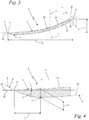
- Fig. 3 shows in a cross-sectional view of the cutting portion 3 of the blade wing 2 after Fig. 1 along the section III-III marked there. Accordingly, in the usual installation position, a vertical direction 18 pointing upwards parallel to the rotation axis or vertical axis 1 is predefined, to which all information relating to "above” and “below” refers.
- the cutting section 3 is after Fig. 3 formed as an aerodynamic blade 14, the trailing edge 5 viewed in cross-section of the blade 14 at a height h above the cutting edge 4 is located.
- the blade wing 2 along the radial extent of the blade 14 has a particular continuously curved cross-sectional shape with a concave top.
- the cross-sectional view after Fig. 3 shows, in particular, that the cutting portion 3 has an outgoing from the cutting edge 4 and the trailing edge 5 current, with respect to the vertical direction 18 of the usual installation position upper contour 21.
- These Upper contour 21 of the cross section is determined by the cutting edge 4 over at least half, preferably over at least 75% and in particular over at least 90% of the chord T F by an upper curve 22. In the preferred embodiment shown is about 90% of the chord T F.
- the remaining part, here about 8% of the chord T F can be configured in a different manner, in which case in particular a bevel 23 adjacent to the trailing edge 5 is provided.
- the curvature of the upper curve 22 is preferably zero at the location of the cutting edge 4.
- the upper curve 22 rises in curvature and at least in sections convexly toward the trailing edge 5, for which purpose it is preferably determined by a curvature-constant Bezier polynomial of the third degree.
- the cutting section 3 has a contour 6 extending from the cutting edge 4 and running to the trailing edge 5, relative to the vertical direction 18 of the usual installation position.
- This lower contour 6 of the cross section in turn has a deepest point 7 measured in the vertical direction 18, from which point it rises both in the vertical direction 18 towards the cutting edge 4 and towards the trailing edge 5.
- Said lower contour 6 is determined at least in sections, here completely by a lower curve 8 indicated by dashed lines. Behind the lowest point 7, notably in its related below Fig. 4 described rear curve section 10, the lower curve 8 is equidistant from the upper curve 22, thus here the aerodynamic blade 14 by a sheet having a depth in the direction constant, in Fig. 4 formed material thickness d is formed. Further details emerge from the enlarged detail illustration Fig. 4 ,
- Fig. 4 shows the cutting section 3 in an enlarged detail Fig. 3 in the vicinity of the lowest point 7 and the sharpened cutting edge 4. It can be seen that the upper curve 22 at the location of the cutting edge 4 is not parallel to the horizontal Drehebene E or to the cutting direction 20, but at an entrance angle ⁇ to it.
- the entrance angle ⁇ is advantageously in a range of 0 ° to 5 ° inclusive, and more preferably in a range of 1.5 ° to 3.0 ° inclusive.
- the curve 8, which defines the lower contour 6 of the cross section through the cutting section 3 consists of a front curve section 9 and a rear curve section 10.
- the front curve portion 9 is based on the direction of rotation 17 and the cutting direction 20 before the lowest point 7, while the rear curve section 10 with respect to the direction of rotation 17 and the cutting direction 20 behind the lowest point 7 runs, and wherein both curve sections To hit 10 at the lowest point 7.
- the first mathematical derivative of the lower curve 8 at the lowest point 7 is equal to zero.
- the curve 8 in this case runs perpendicular to the vertical axis 1 or parallel to the plane of rotation E.
- at least the first mathematical derivative, preferably also the second mathematical derivative of the lower curve 8 in the front curve section 9 is continuous, thus the lower curve 8 so kink-free and smoothly curved runs.
- the front curve section 9 and the rear curve section 10 tangentially continuous merge into each other at the lowest point 7, so there also have no kink.
- FIGS. 3 and 4 The synopsis of FIGS. 3 and 4 is still another geometric peculiarity of the cross-sectional design in the cutting section 3 removed.
- the cutting edge 4 is in the vertical direction 18 above the lowest point 7, wherein the Knife blade 2 at the location of the lowest point 7 has a material thickness d.
- the cutting edge 4 in the cross-section of the blade blade 2 considered by the amount of a cutting depth t S in the direction of rotation 17 before the lowest point 7.
- the ratio of the cutting depth t S to the material thickness d is in a range of 6.0 inclusive inclusive , 0 and in particular within the range of 5.0 to 3.0 inclusive.
- Fig. 2 shows a front view of the knife blade 2 after the FIGS. 1 . 3 and 4 in the area of the cutting section 3. 3 designed as an aerodynamic blade 14. While along the radial direction, for each cross section through the cutting section 3, this is associated with the cutting section 3 FIGS. 3 and 4 described design principle applies, therefore, in particular the position of the trailing edge at a height h above the cutting edge 4 applies, it follows from the front view Fig. 2 even a gradual change in the relevant absolute numerical values. In the preferred embodiment shown according to Fig. 2 Namely takes the said height h along the cutting portion 3 from radially inward to radially outward.
- the height h at the radially inner end of the cutting portion 3 is an inner height h i and at the radially outer end of the cutting portion 3 an outer height h a , wherein the inner height h i is greater than the outer height h a .
- a height difference ⁇ h Between the inner height h i and the outer height h a results according to the illustration Fig. 2 a height difference ⁇ h .
- the ratio of the height difference ⁇ h to the average chord length T F is preferably in a range from 0.15 to 0.3 inclusive, and more particularly in a range from 0.15 to and including 0.2. From the synopsis of Figures 1 and 2 It can also be concluded that the ratio of the inner height h i to the mean chord T F is advantageously in a range of 0.25 to 0.45 inclusive and more particularly in a range of 0.30 to 0.40 inclusive.
- FIGS. 1, 2 and 5 shows that the cross section of the blade wing 2 in the deformation zone 16 is hardly curved and almost rectilinear, and consequently in comparison to the root portion 11 and also to the cutting portion 3 has a reduced rigidity and also a reduced strength.
- the moment of inertia acting in the vertical direction 18 and in particular the mechanical moment of resistance of the deformation zone 16 acting in the vertical direction 18 are reduced in relation to the corresponding values of the root section 1 and the cutting section 3 such that the cutting section 3 yields in the case of overload with respect to the root section 11 and radially afterwards can deflect above.
- Fig. 5 shows in a front view the knife after the Fig. 1 to 4 with details of the cross-sectional distribution in the area of the cutting section 3. It has already been pointed out above that the inner height h i is greater than the outer height h a . This can be achieved, for example, by a sharpening of the knife outline, possibly also in combination with a non-twisted, that is unrestricted cross-sectional profile.
- the blade wing 2 in the area of the blade 14 has an at least approximately constant blade depth T F along the radial extent and, moreover, is provided with a geometric offset, ie with a cross-sectional rotation carried out along the radial direction such that the height h of the inner height h i to the outer height h a decreases.
- a radially inner cross-section 25 of the cutting area 3 is indicated by dashed lines in addition to the radially outer cross-section which is already recognizable in this view. In both cases, a contact line is in each case drawn, which rests tangent-like on the respective upper side of the two mentioned reference cross sections 24, 25.
- These contact lines each indicate an angle of incidence ⁇ relative to the cutting direction 20. Due to the constant chord T F in conjunction with the difference between the inner height h i and the outer height h a, there is also a cross-sectional rotation along the radial extent of the cutting portion 3 with an inner angle ⁇ i and an outer angle ⁇ a .
- the angle of attack ⁇ spans in the illustrated embodiment, a range of the inner angle of attack ⁇ i with about 16 ° to the outer angle ⁇ a with about 12 °. But it can also be appropriate angle courses, which are approximately in a range of 25 ° to 5 ° and in particular from about 20 ° to 10 °.
Landscapes
- Life Sciences & Earth Sciences (AREA)
- Environmental Sciences (AREA)
- Harvester Elements (AREA)
Priority Applications (1)
| Application Number | Priority Date | Filing Date | Title |
|---|---|---|---|
| PL18157324T PL3366103T3 (pl) | 2017-02-25 | 2018-02-19 | Nóż kosiarki |
Applications Claiming Priority (1)
| Application Number | Priority Date | Filing Date | Title |
|---|---|---|---|
| DE102017001859.6A DE102017001859A1 (de) | 2017-02-25 | 2017-02-25 | Messer eines Rasenmähers |
Publications (2)
| Publication Number | Publication Date |
|---|---|
| EP3366103A1 EP3366103A1 (de) | 2018-08-29 |
| EP3366103B1 true EP3366103B1 (de) | 2019-09-04 |
Family
ID=61244432
Family Applications (1)
| Application Number | Title | Priority Date | Filing Date |
|---|---|---|---|
| EP18157324.7A Active EP3366103B1 (de) | 2017-02-25 | 2018-02-19 | Messer eines rasenmähers |
Country Status (3)
| Country | Link |
|---|---|
| EP (1) | EP3366103B1 (pl) |
| DE (1) | DE102017001859A1 (pl) |
| PL (1) | PL3366103T3 (pl) |
Cited By (1)
| Publication number | Priority date | Publication date | Assignee | Title |
|---|---|---|---|---|
| US20230090730A1 (en) * | 2021-09-17 | 2023-03-23 | Scythe Robotics, Inc. | Mower components |
Families Citing this family (1)
| Publication number | Priority date | Publication date | Assignee | Title |
|---|---|---|---|---|
| CN113115623B (zh) * | 2020-01-10 | 2025-02-28 | 南京泉峰科技有限公司 | 一种用于割草机的切割刀片及割草机 |
Family Cites Families (4)
| Publication number | Priority date | Publication date | Assignee | Title |
|---|---|---|---|---|
| FR2611422A1 (fr) * | 1987-03-05 | 1988-09-09 | Margerides Sa Forges | Lame de tondeuse a gazon rotative comportant des moyens d'abaissement du niveau sonore |
| US6978590B1 (en) * | 2004-11-19 | 2005-12-27 | John Graham | Lawn mower blade improvement |
| US7299612B2 (en) * | 2006-03-30 | 2007-11-27 | John Schuyler | Rotary mower blade |
| JP6151659B2 (ja) * | 2014-03-27 | 2017-06-21 | 本田技研工業株式会社 | 芝刈機 |
-
2017
- 2017-02-25 DE DE102017001859.6A patent/DE102017001859A1/de not_active Withdrawn
-
2018
- 2018-02-19 EP EP18157324.7A patent/EP3366103B1/de active Active
- 2018-02-19 PL PL18157324T patent/PL3366103T3/pl unknown
Non-Patent Citations (1)
| Title |
|---|
| None * |
Cited By (1)
| Publication number | Priority date | Publication date | Assignee | Title |
|---|---|---|---|---|
| US20230090730A1 (en) * | 2021-09-17 | 2023-03-23 | Scythe Robotics, Inc. | Mower components |
Also Published As
| Publication number | Publication date |
|---|---|
| EP3366103A1 (de) | 2018-08-29 |
| DE102017001859A1 (de) | 2018-08-30 |
| PL3366103T3 (pl) | 2020-04-30 |
Similar Documents
| Publication | Publication Date | Title |
|---|---|---|
| EP2004990B1 (de) | Rotorblatt einer windenergieanlage | |
| DE2950880A1 (de) | Rotierender querstrom-rasenmaeher | |
| EP1186221A1 (de) | Mähwerk, Abweisereinrichtung und Fahrzeug bzw. Gerät | |
| EP3664593B1 (de) | Messerklinge für ein mähmesser einer landwirtschaftlichen erntemaschine | |
| EP3366103A1 (de) | Messer eines rasenmähers | |
| DE102011016284B4 (de) | Scheibenmähwerk | |
| EP2810547B1 (de) | Messer für ein Sichelmähwerk und Sichelmähwerk | |
| EP3969743B1 (de) | Rotorblatt und verfahren zum auslegen eines rotorblatts einer windenergieanlage. | |
| EP1306000B1 (de) | Verfahren zur Optimierung der Erzeugung von qualitativ hochwertigem Futter | |
| DE102016002607A1 (de) | Schneidmesser für einen Werkzeugkopf eines Freischneiders | |
| DE102017112444B4 (de) | Oszillierendes Doppelmesser-Schneidsystem | |
| DE102008049317B4 (de) | Schneidmesser für einen Kreiselmäher, Kreiselmäher mit einem derartigen Schneidmesser sowie Verfahren zum Herstellen eines derartigen Schneidmessers | |
| EP3195718B1 (de) | Schneidmesser für einen werkzeugkopf eines freischneiders | |
| EP4368416A1 (de) | Fahrzeugreifen | |
| EP3545741B1 (de) | Mulchmesser für ein mähgerät | |
| DE10249971B4 (de) | Mäher mit Mulchfunktion | |
| DE4121021A1 (de) | Verfahren und vorrichtung zum trennen oder schlitzen eines starren schnittguts | |
| DE2627099A1 (de) | Gehaeuse fuer motorrasenmaeher | |
| DE202008018560U1 (de) | Schneidmesser für einen Kreiselmäher sowie Kreiselmäher mit einem derartigen Schneidmesser | |
| DE10319032B3 (de) | Mäh- und Mulchmesser sowie dessen Anordnung in Sichelmähern | |
| DE2032483A1 (de) | Sichel Rasenmäher mit fahr barer Grundplatte | |
| AT513396B1 (de) | Schneidvorrichtung für einen Rasenmäher | |
| DE102013101968B4 (de) | Schlegelmesser sowie Messerwelle hierfür | |
| DE3839918C2 (pl) | ||
| EP2111736B1 (de) | Messerbalken |
Legal Events
| Date | Code | Title | Description |
|---|---|---|---|
| PUAI | Public reference made under article 153(3) epc to a published international application that has entered the european phase |
Free format text: ORIGINAL CODE: 0009012 |
|
| STAA | Information on the status of an ep patent application or granted ep patent |
Free format text: STATUS: THE APPLICATION HAS BEEN PUBLISHED |
|
| AK | Designated contracting states |
Kind code of ref document: A1 Designated state(s): AL AT BE BG CH CY CZ DE DK EE ES FI FR GB GR HR HU IE IS IT LI LT LU LV MC MK MT NL NO PL PT RO RS SE SI SK SM TR |
|
| AX | Request for extension of the european patent |
Extension state: BA ME |
|
| STAA | Information on the status of an ep patent application or granted ep patent |
Free format text: STATUS: REQUEST FOR EXAMINATION WAS MADE |
|
| RAP1 | Party data changed (applicant data changed or rights of an application transferred) |
Owner name: ANDREAS STIHL AG & CO. KG |
|
| 17P | Request for examination filed |
Effective date: 20190114 |
|
| RBV | Designated contracting states (corrected) |
Designated state(s): AL AT BE BG CH CY CZ DE DK EE ES FI FR GB GR HR HU IE IS IT LI LT LU LV MC MK MT NL NO PL PT RO RS SE SI SK SM TR |
|
| GRAP | Despatch of communication of intention to grant a patent |
Free format text: ORIGINAL CODE: EPIDOSNIGR1 |
|
| STAA | Information on the status of an ep patent application or granted ep patent |
Free format text: STATUS: GRANT OF PATENT IS INTENDED |
|
| INTG | Intention to grant announced |
Effective date: 20190328 |
|
| GRAS | Grant fee paid |
Free format text: ORIGINAL CODE: EPIDOSNIGR3 |
|
| GRAA | (expected) grant |
Free format text: ORIGINAL CODE: 0009210 |
|
| STAA | Information on the status of an ep patent application or granted ep patent |
Free format text: STATUS: THE PATENT HAS BEEN GRANTED |
|
| AK | Designated contracting states |
Kind code of ref document: B1 Designated state(s): AL AT BE BG CH CY CZ DE DK EE ES FI FR GB GR HR HU IE IS IT LI LT LU LV MC MK MT NL NO PL PT RO RS SE SI SK SM TR |
|
| REG | Reference to a national code |
Ref country code: GB Ref legal event code: FG4D Free format text: NOT ENGLISH |
|
| REG | Reference to a national code |
Ref country code: CH Ref legal event code: EP |
|
| REG | Reference to a national code |
Ref country code: AT Ref legal event code: REF Ref document number: 1174071 Country of ref document: AT Kind code of ref document: T Effective date: 20190915 |
|
| REG | Reference to a national code |
Ref country code: DE Ref legal event code: R096 Ref document number: 502018000178 Country of ref document: DE |
|
| REG | Reference to a national code |
Ref country code: IE Ref legal event code: FG4D Free format text: LANGUAGE OF EP DOCUMENT: GERMAN |
|
| REG | Reference to a national code |
Ref country code: NL Ref legal event code: MP Effective date: 20190904 |
|
| REG | Reference to a national code |
Ref country code: LT Ref legal event code: MG4D |
|
| PG25 | Lapsed in a contracting state [announced via postgrant information from national office to epo] |
Ref country code: NO Free format text: LAPSE BECAUSE OF FAILURE TO SUBMIT A TRANSLATION OF THE DESCRIPTION OR TO PAY THE FEE WITHIN THE PRESCRIBED TIME-LIMIT Effective date: 20191204 Ref country code: LT Free format text: LAPSE BECAUSE OF FAILURE TO SUBMIT A TRANSLATION OF THE DESCRIPTION OR TO PAY THE FEE WITHIN THE PRESCRIBED TIME-LIMIT Effective date: 20190904 Ref country code: BG Free format text: LAPSE BECAUSE OF FAILURE TO SUBMIT A TRANSLATION OF THE DESCRIPTION OR TO PAY THE FEE WITHIN THE PRESCRIBED TIME-LIMIT Effective date: 20191204 Ref country code: FI Free format text: LAPSE BECAUSE OF FAILURE TO SUBMIT A TRANSLATION OF THE DESCRIPTION OR TO PAY THE FEE WITHIN THE PRESCRIBED TIME-LIMIT Effective date: 20190904 Ref country code: HR Free format text: LAPSE BECAUSE OF FAILURE TO SUBMIT A TRANSLATION OF THE DESCRIPTION OR TO PAY THE FEE WITHIN THE PRESCRIBED TIME-LIMIT Effective date: 20190904 Ref country code: SE Free format text: LAPSE BECAUSE OF FAILURE TO SUBMIT A TRANSLATION OF THE DESCRIPTION OR TO PAY THE FEE WITHIN THE PRESCRIBED TIME-LIMIT Effective date: 20190904 |
|
| PG25 | Lapsed in a contracting state [announced via postgrant information from national office to epo] |
Ref country code: LV Free format text: LAPSE BECAUSE OF FAILURE TO SUBMIT A TRANSLATION OF THE DESCRIPTION OR TO PAY THE FEE WITHIN THE PRESCRIBED TIME-LIMIT Effective date: 20190904 Ref country code: ES Free format text: LAPSE BECAUSE OF FAILURE TO SUBMIT A TRANSLATION OF THE DESCRIPTION OR TO PAY THE FEE WITHIN THE PRESCRIBED TIME-LIMIT Effective date: 20190904 Ref country code: GR Free format text: LAPSE BECAUSE OF FAILURE TO SUBMIT A TRANSLATION OF THE DESCRIPTION OR TO PAY THE FEE WITHIN THE PRESCRIBED TIME-LIMIT Effective date: 20191205 Ref country code: AL Free format text: LAPSE BECAUSE OF FAILURE TO SUBMIT A TRANSLATION OF THE DESCRIPTION OR TO PAY THE FEE WITHIN THE PRESCRIBED TIME-LIMIT Effective date: 20190904 Ref country code: RS Free format text: LAPSE BECAUSE OF FAILURE TO SUBMIT A TRANSLATION OF THE DESCRIPTION OR TO PAY THE FEE WITHIN THE PRESCRIBED TIME-LIMIT Effective date: 20190904 |
|
| PG25 | Lapsed in a contracting state [announced via postgrant information from national office to epo] |
Ref country code: IT Free format text: LAPSE BECAUSE OF FAILURE TO SUBMIT A TRANSLATION OF THE DESCRIPTION OR TO PAY THE FEE WITHIN THE PRESCRIBED TIME-LIMIT Effective date: 20190904 Ref country code: EE Free format text: LAPSE BECAUSE OF FAILURE TO SUBMIT A TRANSLATION OF THE DESCRIPTION OR TO PAY THE FEE WITHIN THE PRESCRIBED TIME-LIMIT Effective date: 20190904 Ref country code: RO Free format text: LAPSE BECAUSE OF FAILURE TO SUBMIT A TRANSLATION OF THE DESCRIPTION OR TO PAY THE FEE WITHIN THE PRESCRIBED TIME-LIMIT Effective date: 20190904 Ref country code: NL Free format text: LAPSE BECAUSE OF FAILURE TO SUBMIT A TRANSLATION OF THE DESCRIPTION OR TO PAY THE FEE WITHIN THE PRESCRIBED TIME-LIMIT Effective date: 20190904 Ref country code: PT Free format text: LAPSE BECAUSE OF FAILURE TO SUBMIT A TRANSLATION OF THE DESCRIPTION OR TO PAY THE FEE WITHIN THE PRESCRIBED TIME-LIMIT Effective date: 20200106 |
|
| PG25 | Lapsed in a contracting state [announced via postgrant information from national office to epo] |
Ref country code: IS Free format text: LAPSE BECAUSE OF FAILURE TO SUBMIT A TRANSLATION OF THE DESCRIPTION OR TO PAY THE FEE WITHIN THE PRESCRIBED TIME-LIMIT Effective date: 20200224 Ref country code: SK Free format text: LAPSE BECAUSE OF FAILURE TO SUBMIT A TRANSLATION OF THE DESCRIPTION OR TO PAY THE FEE WITHIN THE PRESCRIBED TIME-LIMIT Effective date: 20190904 Ref country code: CZ Free format text: LAPSE BECAUSE OF FAILURE TO SUBMIT A TRANSLATION OF THE DESCRIPTION OR TO PAY THE FEE WITHIN THE PRESCRIBED TIME-LIMIT Effective date: 20190904 Ref country code: SM Free format text: LAPSE BECAUSE OF FAILURE TO SUBMIT A TRANSLATION OF THE DESCRIPTION OR TO PAY THE FEE WITHIN THE PRESCRIBED TIME-LIMIT Effective date: 20190904 |
|
| REG | Reference to a national code |
Ref country code: DE Ref legal event code: R097 Ref document number: 502018000178 Country of ref document: DE |
|
| PLBE | No opposition filed within time limit |
Free format text: ORIGINAL CODE: 0009261 |
|
| STAA | Information on the status of an ep patent application or granted ep patent |
Free format text: STATUS: NO OPPOSITION FILED WITHIN TIME LIMIT |
|
| PG2D | Information on lapse in contracting state deleted |
Ref country code: IS |
|
| PG25 | Lapsed in a contracting state [announced via postgrant information from national office to epo] |
Ref country code: DK Free format text: LAPSE BECAUSE OF FAILURE TO SUBMIT A TRANSLATION OF THE DESCRIPTION OR TO PAY THE FEE WITHIN THE PRESCRIBED TIME-LIMIT Effective date: 20190904 Ref country code: IS Free format text: LAPSE BECAUSE OF FAILURE TO SUBMIT A TRANSLATION OF THE DESCRIPTION OR TO PAY THE FEE WITHIN THE PRESCRIBED TIME-LIMIT Effective date: 20200105 |
|
| 26N | No opposition filed |
Effective date: 20200605 |
|
| PG25 | Lapsed in a contracting state [announced via postgrant information from national office to epo] |
Ref country code: SI Free format text: LAPSE BECAUSE OF FAILURE TO SUBMIT A TRANSLATION OF THE DESCRIPTION OR TO PAY THE FEE WITHIN THE PRESCRIBED TIME-LIMIT Effective date: 20190904 |
|
| PG25 | Lapsed in a contracting state [announced via postgrant information from national office to epo] |
Ref country code: LU Free format text: LAPSE BECAUSE OF NON-PAYMENT OF DUE FEES Effective date: 20200219 Ref country code: MC Free format text: LAPSE BECAUSE OF FAILURE TO SUBMIT A TRANSLATION OF THE DESCRIPTION OR TO PAY THE FEE WITHIN THE PRESCRIBED TIME-LIMIT Effective date: 20190904 |
|
| PG25 | Lapsed in a contracting state [announced via postgrant information from national office to epo] |
Ref country code: IE Free format text: LAPSE BECAUSE OF NON-PAYMENT OF DUE FEES Effective date: 20200219 |
|
| PG25 | Lapsed in a contracting state [announced via postgrant information from national office to epo] |
Ref country code: LI Free format text: LAPSE BECAUSE OF NON-PAYMENT OF DUE FEES Effective date: 20210228 Ref country code: CH Free format text: LAPSE BECAUSE OF NON-PAYMENT OF DUE FEES Effective date: 20210228 |
|
| PG25 | Lapsed in a contracting state [announced via postgrant information from national office to epo] |
Ref country code: TR Free format text: LAPSE BECAUSE OF FAILURE TO SUBMIT A TRANSLATION OF THE DESCRIPTION OR TO PAY THE FEE WITHIN THE PRESCRIBED TIME-LIMIT Effective date: 20190904 Ref country code: MT Free format text: LAPSE BECAUSE OF FAILURE TO SUBMIT A TRANSLATION OF THE DESCRIPTION OR TO PAY THE FEE WITHIN THE PRESCRIBED TIME-LIMIT Effective date: 20190904 Ref country code: CY Free format text: LAPSE BECAUSE OF FAILURE TO SUBMIT A TRANSLATION OF THE DESCRIPTION OR TO PAY THE FEE WITHIN THE PRESCRIBED TIME-LIMIT Effective date: 20190904 |
|
| PG25 | Lapsed in a contracting state [announced via postgrant information from national office to epo] |
Ref country code: MK Free format text: LAPSE BECAUSE OF FAILURE TO SUBMIT A TRANSLATION OF THE DESCRIPTION OR TO PAY THE FEE WITHIN THE PRESCRIBED TIME-LIMIT Effective date: 20190904 |
|
| GBPC | Gb: european patent ceased through non-payment of renewal fee |
Effective date: 20220219 |
|
| PG25 | Lapsed in a contracting state [announced via postgrant information from national office to epo] |
Ref country code: GB Free format text: LAPSE BECAUSE OF NON-PAYMENT OF DUE FEES Effective date: 20220219 |
|
| PGFP | Annual fee paid to national office [announced via postgrant information from national office to epo] |
Ref country code: PL Payment date: 20230210 Year of fee payment: 6 |
|
| REG | Reference to a national code |
Ref country code: AT Ref legal event code: MM01 Ref document number: 1174071 Country of ref document: AT Kind code of ref document: T Effective date: 20230219 |
|
| PG25 | Lapsed in a contracting state [announced via postgrant information from national office to epo] |
Ref country code: AT Free format text: LAPSE BECAUSE OF NON-PAYMENT OF DUE FEES Effective date: 20230219 |
|
| PG25 | Lapsed in a contracting state [announced via postgrant information from national office to epo] |
Ref country code: AT Free format text: LAPSE BECAUSE OF NON-PAYMENT OF DUE FEES Effective date: 20230219 |
|
| PG25 | Lapsed in a contracting state [announced via postgrant information from national office to epo] |
Ref country code: PL Free format text: LAPSE BECAUSE OF NON-PAYMENT OF DUE FEES Effective date: 20240219 |
|
| PGFP | Annual fee paid to national office [announced via postgrant information from national office to epo] |
Ref country code: DE Payment date: 20260220 Year of fee payment: 9 |
|
| PGFP | Annual fee paid to national office [announced via postgrant information from national office to epo] |
Ref country code: AT Payment date: 20260410 Year of fee payment: 5 |
|
| PGFP | Annual fee paid to national office [announced via postgrant information from national office to epo] |
Ref country code: BE Payment date: 20260220 Year of fee payment: 9 |
|
| PGFP | Annual fee paid to national office [announced via postgrant information from national office to epo] |
Ref country code: FR Payment date: 20260224 Year of fee payment: 9 |