EP3365668B1 - Festphasenextraktion mit kapillarelektrophorese - Google Patents
Festphasenextraktion mit kapillarelektrophorese Download PDFInfo
- Publication number
- EP3365668B1 EP3365668B1 EP16781227.0A EP16781227A EP3365668B1 EP 3365668 B1 EP3365668 B1 EP 3365668B1 EP 16781227 A EP16781227 A EP 16781227A EP 3365668 B1 EP3365668 B1 EP 3365668B1
- Authority
- EP
- European Patent Office
- Prior art keywords
- sample
- reservoir
- channel
- spe
- bge
- Prior art date
- Legal status (The legal status is an assumption and is not a legal conclusion. Google has not performed a legal analysis and makes no representation as to the accuracy of the status listed.)
- Active
Links
- 238000002414 normal-phase solid-phase extraction Methods 0.000 title claims description 166
- 238000005251 capillar electrophoresis Methods 0.000 title description 43
- 238000000926 separation method Methods 0.000 claims description 227
- 238000000034 method Methods 0.000 claims description 124
- 239000002699 waste material Substances 0.000 claims description 90
- 239000012530 fluid Substances 0.000 claims description 89
- 239000012491 analyte Substances 0.000 claims description 54
- 238000004891 communication Methods 0.000 claims description 51
- 238000004458 analytical method Methods 0.000 claims description 50
- 239000003792 electrolyte Substances 0.000 claims description 33
- 238000012545 processing Methods 0.000 claims description 33
- 238000010828 elution Methods 0.000 claims description 32
- 230000000903 blocking effect Effects 0.000 claims description 23
- 150000002500 ions Chemical class 0.000 claims description 21
- 239000003795 chemical substances by application Substances 0.000 claims description 16
- 230000003750 conditioning effect Effects 0.000 claims description 15
- 238000003825 pressing Methods 0.000 claims description 6
- 230000003595 spectral effect Effects 0.000 claims description 3
- 238000007787 electrohydrodynamic spraying Methods 0.000 claims description 2
- 239000000523 sample Substances 0.000 description 365
- 238000002347 injection Methods 0.000 description 76
- 239000007924 injection Substances 0.000 description 76
- 108090000765 processed proteins & peptides Proteins 0.000 description 59
- 238000001962 electrophoresis Methods 0.000 description 53
- 239000000463 material Substances 0.000 description 36
- 239000007789 gas Substances 0.000 description 35
- 239000000203 mixture Substances 0.000 description 34
- 102000004196 processed proteins & peptides Human genes 0.000 description 32
- 238000000132 electrospray ionisation Methods 0.000 description 31
- DTQVDTLACAAQTR-UHFFFAOYSA-N Trifluoroacetic acid Chemical compound OC(=O)C(F)(F)F DTQVDTLACAAQTR-UHFFFAOYSA-N 0.000 description 29
- 230000037230 mobility Effects 0.000 description 24
- 238000011068 loading method Methods 0.000 description 23
- OKKJLVBELUTLKV-UHFFFAOYSA-N Methanol Chemical compound OC OKKJLVBELUTLKV-UHFFFAOYSA-N 0.000 description 21
- 150000003839 salts Chemical class 0.000 description 21
- YFGBQHOOROIVKG-BHDDXSALSA-N (2R)-2-[[(2R)-2-[[2-[[2-[[(2S)-2-amino-3-(4-hydroxyphenyl)propanoyl]amino]acetyl]amino]acetyl]amino]-3-phenylpropanoyl]amino]-4-methylsulfanylbutanoic acid Chemical compound C([C@H](C(=O)N[C@H](CCSC)C(O)=O)NC(=O)CNC(=O)CNC(=O)[C@@H](N)CC=1C=CC(O)=CC=1)C1=CC=CC=C1 YFGBQHOOROIVKG-BHDDXSALSA-N 0.000 description 17
- 102400000988 Met-enkephalin Human genes 0.000 description 17
- 108010042237 Methionine Enkephalin Proteins 0.000 description 17
- 102400000967 Bradykinin Human genes 0.000 description 16
- 101800004538 Bradykinin Proteins 0.000 description 16
- QXZGBUJJYSLZLT-UHFFFAOYSA-N H-Arg-Pro-Pro-Gly-Phe-Ser-Pro-Phe-Arg-OH Natural products NC(N)=NCCCC(N)C(=O)N1CCCC1C(=O)N1C(C(=O)NCC(=O)NC(CC=2C=CC=CC=2)C(=O)NC(CO)C(=O)N2C(CCC2)C(=O)NC(CC=2C=CC=CC=2)C(=O)NC(CCCN=C(N)N)C(O)=O)CCC1 QXZGBUJJYSLZLT-UHFFFAOYSA-N 0.000 description 16
- QXZGBUJJYSLZLT-FDISYFBBSA-N bradykinin Chemical compound NC(=N)NCCC[C@H](N)C(=O)N1CCC[C@H]1C(=O)N1[C@H](C(=O)NCC(=O)N[C@@H](CC=2C=CC=CC=2)C(=O)N[C@@H](CO)C(=O)N2[C@@H](CCC2)C(=O)N[C@@H](CC=2C=CC=CC=2)C(=O)N[C@@H](CCCNC(N)=N)C(O)=O)CCC1 QXZGBUJJYSLZLT-FDISYFBBSA-N 0.000 description 16
- 238000001514 detection method Methods 0.000 description 16
- 230000002829 reductive effect Effects 0.000 description 16
- 238000004094 preconcentration Methods 0.000 description 15
- 230000005526 G1 to G0 transition Effects 0.000 description 14
- 102400000160 Thymopentin Human genes 0.000 description 14
- 101800001703 Thymopentin Proteins 0.000 description 14
- 230000005684 electric field Effects 0.000 description 14
- 238000013508 migration Methods 0.000 description 14
- 230000005012 migration Effects 0.000 description 14
- 239000002594 sorbent Substances 0.000 description 14
- PSWFFKRAVBDQEG-YGQNSOCVSA-N thymopentin Chemical compound NC(N)=NCCC[C@H](N)C(=O)N[C@@H](CCCCN)C(=O)N[C@@H](CC(O)=O)C(=O)N[C@@H](C(C)C)C(=O)N[C@H](C(O)=O)CC1=CC=C(O)C=C1 PSWFFKRAVBDQEG-YGQNSOCVSA-N 0.000 description 14
- 229960004517 thymopentin Drugs 0.000 description 14
- 238000000738 capillary electrophoresis-mass spectrometry Methods 0.000 description 13
- BDAGIHXWWSANSR-UHFFFAOYSA-N methanoic acid Natural products OC=O BDAGIHXWWSANSR-UHFFFAOYSA-N 0.000 description 12
- 239000012071 phase Substances 0.000 description 12
- XLYOFNOQVPJJNP-UHFFFAOYSA-N water Substances O XLYOFNOQVPJJNP-UHFFFAOYSA-N 0.000 description 12
- 102400000345 Angiotensin-2 Human genes 0.000 description 11
- 101800000733 Angiotensin-2 Proteins 0.000 description 11
- CZGUSIXMZVURDU-JZXHSEFVSA-N Ile(5)-angiotensin II Chemical compound C([C@@H](C(=O)N[C@@H]([C@@H](C)CC)C(=O)N[C@@H](CC=1NC=NC=1)C(=O)N1[C@@H](CCC1)C(=O)N[C@@H](CC=1C=CC=CC=1)C([O-])=O)NC(=O)[C@@H](NC(=O)[C@H](CCCNC(N)=[NH2+])NC(=O)[C@@H]([NH3+])CC([O-])=O)C(C)C)C1=CC=C(O)C=C1 CZGUSIXMZVURDU-JZXHSEFVSA-N 0.000 description 11
- 229950006323 angiotensin ii Drugs 0.000 description 11
- 239000007788 liquid Substances 0.000 description 11
- 239000002904 solvent Substances 0.000 description 11
- 108010091748 peptide A Proteins 0.000 description 10
- 230000008569 process Effects 0.000 description 10
- 230000000717 retained effect Effects 0.000 description 10
- WEVYAHXRMPXWCK-UHFFFAOYSA-N Acetonitrile Chemical compound CC#N WEVYAHXRMPXWCK-UHFFFAOYSA-N 0.000 description 9
- 238000010586 diagram Methods 0.000 description 9
- 238000004590 computer program Methods 0.000 description 8
- 230000014759 maintenance of location Effects 0.000 description 8
- 239000007921 spray Substances 0.000 description 8
- 238000012546 transfer Methods 0.000 description 8
- 239000003643 water by type Substances 0.000 description 8
- 108010065081 Phosphorylase b Proteins 0.000 description 7
- 230000003247 decreasing effect Effects 0.000 description 7
- 230000006870 function Effects 0.000 description 7
- 239000000243 solution Substances 0.000 description 7
- 239000000758 substrate Substances 0.000 description 7
- 238000013022 venting Methods 0.000 description 7
- 238000005406 washing Methods 0.000 description 7
- OSWFIVFLDKOXQC-UHFFFAOYSA-N 4-(3-methoxyphenyl)aniline Chemical compound COC1=CC=CC(C=2C=CC(N)=CC=2)=C1 OSWFIVFLDKOXQC-UHFFFAOYSA-N 0.000 description 6
- 241000588724 Escherichia coli Species 0.000 description 6
- 230000008878 coupling Effects 0.000 description 6
- 238000010168 coupling process Methods 0.000 description 6
- 238000005859 coupling reaction Methods 0.000 description 6
- -1 features Substances 0.000 description 6
- 235000019253 formic acid Nutrition 0.000 description 6
- 238000005342 ion exchange Methods 0.000 description 6
- 238000004949 mass spectrometry Methods 0.000 description 6
- 239000002245 particle Substances 0.000 description 6
- 229920006395 saturated elastomer Polymers 0.000 description 6
- 230000035945 sensitivity Effects 0.000 description 6
- 239000000126 substance Substances 0.000 description 6
- CSCPPACGZOOCGX-UHFFFAOYSA-N Acetone Chemical compound CC(C)=O CSCPPACGZOOCGX-UHFFFAOYSA-N 0.000 description 5
- 101800005149 Peptide B Proteins 0.000 description 5
- 239000012298 atmosphere Substances 0.000 description 5
- 230000008901 benefit Effects 0.000 description 5
- 238000002330 electrospray ionisation mass spectrometry Methods 0.000 description 5
- 239000012156 elution solvent Substances 0.000 description 5
- 238000002474 experimental method Methods 0.000 description 5
- 230000000670 limiting effect Effects 0.000 description 5
- 230000003287 optical effect Effects 0.000 description 5
- 238000012856 packing Methods 0.000 description 5
- 102000004169 proteins and genes Human genes 0.000 description 5
- 108090000623 proteins and genes Proteins 0.000 description 5
- 239000002002 slurry Substances 0.000 description 5
- 238000004885 tandem mass spectrometry Methods 0.000 description 5
- IJGRMHOSHXDMSA-UHFFFAOYSA-N Atomic nitrogen Chemical compound N#N IJGRMHOSHXDMSA-UHFFFAOYSA-N 0.000 description 4
- FAPWRFPIFSIZLT-UHFFFAOYSA-M Sodium chloride Chemical compound [Na+].[Cl-] FAPWRFPIFSIZLT-UHFFFAOYSA-M 0.000 description 4
- 238000013459 approach Methods 0.000 description 4
- 238000009739 binding Methods 0.000 description 4
- 239000003153 chemical reaction reagent Substances 0.000 description 4
- 230000000694 effects Effects 0.000 description 4
- 239000011521 glass Substances 0.000 description 4
- 238000002013 hydrophilic interaction chromatography Methods 0.000 description 4
- 238000002218 isotachophoresis Methods 0.000 description 4
- 239000011159 matrix material Substances 0.000 description 4
- 230000009467 reduction Effects 0.000 description 4
- 101150041393 rsd gene Proteins 0.000 description 4
- 230000001052 transient effect Effects 0.000 description 4
- USFZMSVCRYTOJT-UHFFFAOYSA-N Ammonium acetate Chemical compound N.CC(O)=O USFZMSVCRYTOJT-UHFFFAOYSA-N 0.000 description 3
- 239000005695 Ammonium acetate Substances 0.000 description 3
- VYPSYNLAJGMNEJ-UHFFFAOYSA-N Silicium dioxide Chemical compound O=[Si]=O VYPSYNLAJGMNEJ-UHFFFAOYSA-N 0.000 description 3
- 230000002378 acidificating effect Effects 0.000 description 3
- 235000019257 ammonium acetate Nutrition 0.000 description 3
- 229940043376 ammonium acetate Drugs 0.000 description 3
- 230000006399 behavior Effects 0.000 description 3
- 230000008859 change Effects 0.000 description 3
- 238000004587 chromatography analysis Methods 0.000 description 3
- 230000001143 conditioned effect Effects 0.000 description 3
- 238000005370 electroosmosis Methods 0.000 description 3
- 238000002101 electrospray ionisation tandem mass spectrometry Methods 0.000 description 3
- 239000002609 medium Substances 0.000 description 3
- 229920003229 poly(methyl methacrylate) Polymers 0.000 description 3
- 229920000642 polymer Polymers 0.000 description 3
- 239000004926 polymethyl methacrylate Substances 0.000 description 3
- 238000005086 pumping Methods 0.000 description 3
- 239000012925 reference material Substances 0.000 description 3
- 238000001044 reversed-phase solid-phase extraction Methods 0.000 description 3
- 230000002441 reversible effect Effects 0.000 description 3
- 241000894007 species Species 0.000 description 3
- 238000003860 storage Methods 0.000 description 3
- 238000011144 upstream manufacturing Methods 0.000 description 3
- 239000003463 adsorbent Substances 0.000 description 2
- 239000008280 blood Substances 0.000 description 2
- 210000004369 blood Anatomy 0.000 description 2
- 239000000872 buffer Substances 0.000 description 2
- 239000011248 coating agent Substances 0.000 description 2
- 238000000576 coating method Methods 0.000 description 2
- 150000001875 compounds Chemical class 0.000 description 2
- 239000012141 concentrate Substances 0.000 description 2
- 238000012937 correction Methods 0.000 description 2
- 238000011033 desalting Methods 0.000 description 2
- 238000013461 design Methods 0.000 description 2
- 239000004205 dimethyl polysiloxane Substances 0.000 description 2
- 238000011049 filling Methods 0.000 description 2
- 238000009472 formulation Methods 0.000 description 2
- 238000004128 high performance liquid chromatography Methods 0.000 description 2
- 230000002209 hydrophobic effect Effects 0.000 description 2
- 230000006872 improvement Effects 0.000 description 2
- 239000012535 impurity Substances 0.000 description 2
- 238000011065 in-situ storage Methods 0.000 description 2
- 230000010354 integration Effects 0.000 description 2
- 238000004895 liquid chromatography mass spectrometry Methods 0.000 description 2
- 239000011244 liquid electrolyte Substances 0.000 description 2
- 239000002207 metabolite Substances 0.000 description 2
- 229910052751 metal Inorganic materials 0.000 description 2
- 239000002184 metal Substances 0.000 description 2
- 238000012986 modification Methods 0.000 description 2
- 230000004048 modification Effects 0.000 description 2
- 230000007935 neutral effect Effects 0.000 description 2
- 229910052757 nitrogen Inorganic materials 0.000 description 2
- 238000005457 optimization Methods 0.000 description 2
- 239000003960 organic solvent Substances 0.000 description 2
- 230000036961 partial effect Effects 0.000 description 2
- 229920000435 poly(dimethylsiloxane) Polymers 0.000 description 2
- 239000004417 polycarbonate Substances 0.000 description 2
- 238000012552 review Methods 0.000 description 2
- 239000012488 sample solution Substances 0.000 description 2
- 239000011780 sodium chloride Substances 0.000 description 2
- WROMPOXWARCANT-UHFFFAOYSA-N tfa trifluoroacetic acid Chemical compound OC(=O)C(F)(F)F.OC(=O)C(F)(F)F WROMPOXWARCANT-UHFFFAOYSA-N 0.000 description 2
- RZVAJINKPMORJF-UHFFFAOYSA-N Acetaminophen Chemical compound CC(=O)NC1=CC=C(O)C=C1 RZVAJINKPMORJF-UHFFFAOYSA-N 0.000 description 1
- QGZKDVFQNNGYKY-UHFFFAOYSA-O Ammonium Chemical compound [NH4+] QGZKDVFQNNGYKY-UHFFFAOYSA-O 0.000 description 1
- YZCKVEUIGOORGS-OUBTZVSYSA-N Deuterium Chemical group [2H] YZCKVEUIGOORGS-OUBTZVSYSA-N 0.000 description 1
- 239000004593 Epoxy Substances 0.000 description 1
- 206010016803 Fluid overload Diseases 0.000 description 1
- 102000002068 Glycopeptides Human genes 0.000 description 1
- 108010015899 Glycopeptides Proteins 0.000 description 1
- DGAQECJNVWCQMB-PUAWFVPOSA-M Ilexoside XXIX Chemical compound C[C@@H]1CC[C@@]2(CC[C@@]3(C(=CC[C@H]4[C@]3(CC[C@@H]5[C@@]4(CC[C@@H](C5(C)C)OS(=O)(=O)[O-])C)C)[C@@H]2[C@]1(C)O)C)C(=O)O[C@H]6[C@@H]([C@H]([C@@H]([C@H](O6)CO)O)O)O.[Na+] DGAQECJNVWCQMB-PUAWFVPOSA-M 0.000 description 1
- 102000004856 Lectins Human genes 0.000 description 1
- 108090001090 Lectins Proteins 0.000 description 1
- NQTADLQHYWFPDB-UHFFFAOYSA-N N-Hydroxysuccinimide Chemical compound ON1C(=O)CCC1=O NQTADLQHYWFPDB-UHFFFAOYSA-N 0.000 description 1
- 108010001441 Phosphopeptides Proteins 0.000 description 1
- 239000002202 Polyethylene glycol Substances 0.000 description 1
- 229910052581 Si3N4 Inorganic materials 0.000 description 1
- 102000004142 Trypsin Human genes 0.000 description 1
- 108090000631 Trypsin Proteins 0.000 description 1
- 230000009471 action Effects 0.000 description 1
- 238000001042 affinity chromatography Methods 0.000 description 1
- 150000001413 amino acids Chemical class 0.000 description 1
- 235000013361 beverage Nutrition 0.000 description 1
- 239000012620 biological material Substances 0.000 description 1
- 230000005540 biological transmission Effects 0.000 description 1
- 230000010261 cell growth Effects 0.000 description 1
- 239000000919 ceramic Substances 0.000 description 1
- 238000003776 cleavage reaction Methods 0.000 description 1
- 238000010276 construction Methods 0.000 description 1
- 238000013500 data storage Methods 0.000 description 1
- 229910052805 deuterium Inorganic materials 0.000 description 1
- 238000011161 development Methods 0.000 description 1
- 239000010432 diamond Substances 0.000 description 1
- 229910003460 diamond Inorganic materials 0.000 description 1
- BNIILDVGGAEEIG-UHFFFAOYSA-L disodium hydrogen phosphate Chemical compound [Na+].[Na+].OP([O-])([O-])=O BNIILDVGGAEEIG-UHFFFAOYSA-L 0.000 description 1
- 229910000397 disodium phosphate Inorganic materials 0.000 description 1
- 235000019800 disodium phosphate Nutrition 0.000 description 1
- 229920001971 elastomer Polymers 0.000 description 1
- 239000000806 elastomer Substances 0.000 description 1
- 239000002001 electrolyte material Substances 0.000 description 1
- 230000007613 environmental effect Effects 0.000 description 1
- 238000005530 etching Methods 0.000 description 1
- 238000001704 evaporation Methods 0.000 description 1
- 230000008020 evaporation Effects 0.000 description 1
- 239000002350 fibrinopeptide Substances 0.000 description 1
- 239000004519 grease Substances 0.000 description 1
- 239000001963 growth medium Substances 0.000 description 1
- 239000001307 helium Substances 0.000 description 1
- 229910052734 helium Inorganic materials 0.000 description 1
- SWQJXJOGLNCZEY-UHFFFAOYSA-N helium atom Chemical compound [He] SWQJXJOGLNCZEY-UHFFFAOYSA-N 0.000 description 1
- 239000001257 hydrogen Substances 0.000 description 1
- 229910052739 hydrogen Inorganic materials 0.000 description 1
- 125000004435 hydrogen atom Chemical group [H]* 0.000 description 1
- 239000003547 immunosorbent Substances 0.000 description 1
- 239000011261 inert gas Substances 0.000 description 1
- 230000002401 inhibitory effect Effects 0.000 description 1
- 230000003993 interaction Effects 0.000 description 1
- 238000004255 ion exchange chromatography Methods 0.000 description 1
- 239000002523 lectin Substances 0.000 description 1
- 239000007791 liquid phase Substances 0.000 description 1
- 239000012160 loading buffer Substances 0.000 description 1
- 229920002521 macromolecule Polymers 0.000 description 1
- 238000004519 manufacturing process Methods 0.000 description 1
- 238000013507 mapping Methods 0.000 description 1
- 230000007246 mechanism Effects 0.000 description 1
- 239000012528 membrane Substances 0.000 description 1
- 238000004226 microchip electrophoresis Methods 0.000 description 1
- 238000003801 milling Methods 0.000 description 1
- 238000012544 monitoring process Methods 0.000 description 1
- 238000000465 moulding Methods 0.000 description 1
- 239000002090 nanochannel Substances 0.000 description 1
- 239000002105 nanoparticle Substances 0.000 description 1
- 229910052756 noble gas Inorganic materials 0.000 description 1
- 150000002835 noble gases Chemical class 0.000 description 1
- 102000039446 nucleic acids Human genes 0.000 description 1
- 108020004707 nucleic acids Proteins 0.000 description 1
- 150000007523 nucleic acids Chemical class 0.000 description 1
- 230000001151 other effect Effects 0.000 description 1
- XLYOFNOQVPJJNP-UHFFFAOYSA-O oxonium Chemical compound [OH3+] XLYOFNOQVPJJNP-UHFFFAOYSA-O 0.000 description 1
- 239000005022 packaging material Substances 0.000 description 1
- 238000005192 partition Methods 0.000 description 1
- 238000004810 partition chromatography Methods 0.000 description 1
- 125000001997 phenyl group Chemical group [H]C1=C([H])C([H])=C(*)C([H])=C1[H] 0.000 description 1
- 238000000206 photolithography Methods 0.000 description 1
- 239000004033 plastic Substances 0.000 description 1
- 229920003023 plastic Polymers 0.000 description 1
- BASFCYQUMIYNBI-UHFFFAOYSA-N platinum Chemical compound [Pt] BASFCYQUMIYNBI-UHFFFAOYSA-N 0.000 description 1
- 229920000515 polycarbonate Polymers 0.000 description 1
- 229920001223 polyethylene glycol Polymers 0.000 description 1
- 229920006254 polymer film Polymers 0.000 description 1
- 239000002861 polymer material Substances 0.000 description 1
- 102000040430 polynucleotide Human genes 0.000 description 1
- 108091033319 polynucleotide Proteins 0.000 description 1
- 229920002635 polyurethane Polymers 0.000 description 1
- 239000004814 polyurethane Substances 0.000 description 1
- 239000002243 precursor Substances 0.000 description 1
- 238000003672 processing method Methods 0.000 description 1
- 239000010453 quartz Substances 0.000 description 1
- 238000000581 reactive spray deposition Methods 0.000 description 1
- 230000004044 response Effects 0.000 description 1
- 238000009738 saturating Methods 0.000 description 1
- 230000007017 scission Effects 0.000 description 1
- 210000002966 serum Anatomy 0.000 description 1
- 229910052710 silicon Inorganic materials 0.000 description 1
- 239000010703 silicon Substances 0.000 description 1
- 239000000377 silicon dioxide Substances 0.000 description 1
- HQVNEWCFYHHQES-UHFFFAOYSA-N silicon nitride Chemical compound N12[Si]34N5[Si]62N3[Si]51N64 HQVNEWCFYHHQES-UHFFFAOYSA-N 0.000 description 1
- 150000003384 small molecules Chemical class 0.000 description 1
- 229910052708 sodium Inorganic materials 0.000 description 1
- 239000011734 sodium Substances 0.000 description 1
- 239000007779 soft material Substances 0.000 description 1
- 239000002689 soil Substances 0.000 description 1
- 238000001179 sorption measurement Methods 0.000 description 1
- 230000003068 static effect Effects 0.000 description 1
- 230000001629 suppression Effects 0.000 description 1
- 238000010408 sweeping Methods 0.000 description 1
- GWEVSGVZZGPLCZ-UHFFFAOYSA-N titanium dioxide Inorganic materials O=[Ti]=O GWEVSGVZZGPLCZ-UHFFFAOYSA-N 0.000 description 1
- 239000004408 titanium dioxide Substances 0.000 description 1
- 230000007704 transition Effects 0.000 description 1
- PISDRBMXQBSCIP-UHFFFAOYSA-N trichloro(3,3,4,4,5,5,6,6,7,7,8,8,8-tridecafluorooctyl)silane Chemical compound FC(F)(F)C(F)(F)C(F)(F)C(F)(F)C(F)(F)C(F)(F)CC[Si](Cl)(Cl)Cl PISDRBMXQBSCIP-UHFFFAOYSA-N 0.000 description 1
- 210000002700 urine Anatomy 0.000 description 1
- 230000035899 viability Effects 0.000 description 1
- 230000004304 visual acuity Effects 0.000 description 1
- 238000012800 visualization Methods 0.000 description 1
- 238000003631 wet chemical etching Methods 0.000 description 1
Images


Classifications
-
- G—PHYSICS
- G01—MEASURING; TESTING
- G01N—INVESTIGATING OR ANALYSING MATERIALS BY DETERMINING THEIR CHEMICAL OR PHYSICAL PROPERTIES
- G01N27/00—Investigating or analysing materials by the use of electric, electrochemical, or magnetic means
- G01N27/26—Investigating or analysing materials by the use of electric, electrochemical, or magnetic means by investigating electrochemical variables; by using electrolysis or electrophoresis
- G01N27/416—Systems
- G01N27/447—Systems using electrophoresis
- G01N27/44756—Apparatus specially adapted therefor
- G01N27/44791—Microapparatus
-
- H—ELECTRICITY
- H01—ELECTRIC ELEMENTS
- H01J—ELECTRIC DISCHARGE TUBES OR DISCHARGE LAMPS
- H01J49/00—Particle spectrometers or separator tubes
- H01J49/02—Details
- H01J49/04—Arrangements for introducing or extracting samples to be analysed, e.g. vacuum locks; Arrangements for external adjustment of electron- or ion-optical components
- H01J49/0459—Arrangements for introducing or extracting samples to be analysed, e.g. vacuum locks; Arrangements for external adjustment of electron- or ion-optical components for solid samples
-
- G—PHYSICS
- G01—MEASURING; TESTING
- G01N—INVESTIGATING OR ANALYSING MATERIALS BY DETERMINING THEIR CHEMICAL OR PHYSICAL PROPERTIES
- G01N27/00—Investigating or analysing materials by the use of electric, electrochemical, or magnetic means
- G01N27/26—Investigating or analysing materials by the use of electric, electrochemical, or magnetic means by investigating electrochemical variables; by using electrolysis or electrophoresis
- G01N27/416—Systems
- G01N27/447—Systems using electrophoresis
- G01N27/44704—Details; Accessories
- G01N27/44717—Arrangements for investigating the separated zones, e.g. localising zones
- G01N27/4473—Arrangements for investigating the separated zones, e.g. localising zones by electric means
-
- G—PHYSICS
- G01—MEASURING; TESTING
- G01N—INVESTIGATING OR ANALYSING MATERIALS BY DETERMINING THEIR CHEMICAL OR PHYSICAL PROPERTIES
- G01N27/00—Investigating or analysing materials by the use of electric, electrochemical, or magnetic means
- G01N27/26—Investigating or analysing materials by the use of electric, electrochemical, or magnetic means by investigating electrochemical variables; by using electrolysis or electrophoresis
- G01N27/416—Systems
- G01N27/447—Systems using electrophoresis
- G01N27/44704—Details; Accessories
- G01N27/44743—Introducing samples
-
- H—ELECTRICITY
- H01—ELECTRIC ELEMENTS
- H01J—ELECTRIC DISCHARGE TUBES OR DISCHARGE LAMPS
- H01J49/00—Particle spectrometers or separator tubes
- H01J49/02—Details
- H01J49/10—Ion sources; Ion guns
- H01J49/16—Ion sources; Ion guns using surface ionisation, e.g. field-, thermionic- or photo-emission
- H01J49/165—Electrospray ionisation
Definitions
- This invention is related to sample processing that may be particularly suitable for electrospray ionization and/or sample processing systems that interface with mass spectrometers.
- Electrospray ionization is an important technique for the analysis of biological materials contained in solution by mass spectrometry. See, e.g., Cole, R. B. Electrospray Ionization Mass Spectrometry: Fundamentals, Instrumentation & Applications; John Wiley and Sons, Inc.: New York, 1997 . Electrospray ionization was developed in the late 1980s and was popularized by the work of Fenn. See, e.g., Fenn JB, Mann M, Meng CK, Wong SF & Whitehouse CM (1989), Electrospray ionization for mass-spectrometry of large biomolecules, Science 246, 64-71 .
- electrospray ionization involves the use of electric fields to disperse a sample solution into charged droplets. Through subsequent evaporation of the droplets, analyte ions contained in the droplet are either field emitted from the droplet surface or the ions are desolvated resulting in gas phase analyte ions.
- the source of the liquid exposed to the electric field and to be dispersed is ideally one of small areal extent as the size of the electrospray emitter directly influences the size of droplets produced. Smaller droplets desolvate more rapidly and have fewer molecules present per droplet leading to greater ionization efficiencies.
- These ions can be characterized by a mass analyzer to determine the mass-to-charge ratio. Further analyte structural information can be obtained by employing tandem mass spectrometry techniques.
- Microfluidic capillary electrophoresis with integrated electrospray ionization has been demonstrated as a fast and efficient method of coupling a liquid phase chemical separation with mass spectroscopy detection. See, e.g., Anal. Chem. 2008, 50, 6881-6887 ; and Anal. Chem. 2015, 87, 2264-2272 .
- Conventional microfluidic methods that employ electrokinetic flow of sample into the separation channel are subject to injection bias and cannot effectively be used for some on-device sample focusing methods. Further, the injection of a well-defined band of sample into the separation channel of the microfluidic device can be important to achieving an efficient separation.
- Electrophoretic based techniques including sample stacking, sweeping, pH induced stacking, and transient isotachophoresis (tITP), can be simple to implement and can require little instrumentation development. Unfortunately, these techniques cannot typically load a sample volume larger than the volume of the capillary which limits the achievable concentration and sensitivity improvement. Furthermore, electrophoretic methods often concentrate matrix components equally to the analytes of interest, which can reduce separation performance. Finally, these methods can be limited to a narrow scope of analyte and buffer conditions, and may not be as widely applicable as other sample processing techniques.
- chromatographic-based techniques such as solid phase extraction (SPE)
- SPE solid phase extraction
- electrophoretic-based methods can offer higher pre-concentration values based on the ability to load multiple capillary volumes onto the chromatographic sorbent.
- SPE solid phase extraction
- On-line coupling where the SPE sorbent is separate from the CE capillary but connected via a flow stream with tubing and valves, is the most common method for combining SPE with CE.
- the decoupling of the SPE sorbent from the CE capillary can inhibit or prevent clogging and EOF disruption. Additionally, the inclusion of valves between the SPE sorbent and the CE capillary can direct the matrix components to waste and prevent them from entering the CE capillary.
- on-line coupling of SPE and CE often requires complex instrumentation.
- the transfer of the sample band from the SPE sorbent to the CE capillary typically introduces band broadening, limiting the resulting separation performance.
- dead volume present in the on-line system can dilute the concentrated analyte band, reducing the amount of pre-concentration that can be achieved. Coupling sample processing with CE without sacrificing the separation performance can be a very challenging task.
- WO 98/04909 A1 (Soane Biosciences ) describes integrated electrophoretic microfluidic devices comprising at least an enrichment channel and a main electrophoretic flowpath, as well as methods for their use in electrophoretic applications, are provided.
- the enrichment channel serves to enrich a particular fraction of a liquid sample for subsequent movement through the main electrophoretic flowpath.
- the enrichment channel and electrophoretic flowpath are positioned such that waste fluid from the enrichment channel does not flow through the main electrophoretic flowpath, but instead flows through a discharge outlet.
- Embodiments of the invention are directed to microfluidic sample processing systems and methods that integrate sample processing and employ on-line solid phase extraction (SPE) with microchip CE-ESI and/or microchip CE-detector systems.
- SPE solid phase extraction
- Embodiments of the invention provide fluidic systems and methods that can integrate sample processing with on-line SPE using fluidic devices.
- Embodiments of the invention provide SPE-CE-MS and/or SPE-CE-detector systems and methods that can be configured to eliminate or reduce band broadening imparted on the sample during the transfer between the SPE bed and CE capillary using transient isotachophoresis (tITP) to refocus an analyte band prior to separation.
- tITP transient isotachophoresis
- the tITP can act as a non-linear electrophoretic focusing technique where the sample is sandwiched between a leading fast moving electrolyte (LE) and a trailing slower moving electrolyte (TE). Sample analytes will focus into discreet zones based upon their electrophoretic mobilities.
- CE-ESI-MS and/or CE-optical detector systems can employ fluidic devices with simple, pressure-driven injection methods that can independently be applied to a plurality of different fluid reservoirs.
- pressure-driven sample loading and/or injection methods can also be used with on-device sample focusing methods such as transient isotachophoresis.
- Embodiments of the invention are directed to methods of sample processing.
- the methods include providing a fluidic device with at least one microfluidic or nanofluidic separation channel in fluid communication with a background electrolyte (BGE) reservoir, and a nanofluidic or microfluidic sample channel in fluid communication with the separation channel.
- the sample channel includes at least one solid phase extraction (SPE) bed.
- the device further comprises a sample reservoir in fluid communication with the sample channel, a waste reservoir in fluid communication with the sample channel, and a waste channel that fluidly connects the waste reservoir to the separation channel.
- the method also includes flowing a sample through the sample channel, across the at least one SPE bed, and into the separation channel by pressurizing sealed headspaces of the BGE reservoir, the sample reservoir, and the waste reservoir without applying a voltage to the sample reservoir, to the BGE reservoir, or to the waste reservoir.
- the method includes then electrophoretically separating an analyte component from the sample in the separation channel and performing at least one of: (a) electrospraying the analyte component from at least one emitter in fluid communication with the separation channel toward at least one of a collection device or an inlet of a mass spectrometer; and (b) detecting a signal corresponding to the analyte component in, or emerging from, the separation channel.
- the method can include pre-concentrating the sample prior to the electrophoretic separation.
- the sample can be an ionized sample.
- the pre-concentrating can include flowing the ionized sample in the separation channel in a first direction following a leading electrolyte with a first mobility, and in advance of a trailing electrolyte with a second mobility lower than the first mobility, so that if the sample comprises multiple components, a component of the sample having a highest mobility flows directly behind the leading electrolyte, and a component of the sample having a lowest mobility flows directly in advance of the trailing electrolyte, in the first direction.
- the sample can be flowed across the at least one SPE bed and into the separation channel without directing the sample through a valve.
- the electrophoretically separating the analyte component can include applying an electric field to the fluidic device so that at least a component of the electric field is parallel to an axial direction of a portion of the separation channel.
- the applying the electric field can include applying an electrical potential difference between a first position in the BGE reservoir and a second position downstream from the first position.
- the second position can be located in the separation channel or in a pump channel or in a reservoir in fluid communication with one or both of the separation or the pump channel of the fluidic device.
- the method can include flowing an ion-pairing agent across the at least one SPE bed in advance of, or together with, the sample; rinsing the ion pairing agent from the sample channel into a waste channel in fluid communication with the sample channel; and after rinsing the ion pairing agent from the sample channel, flowing an elution fluid in the sample channel before or during the electrophoretic separation.
- the ion-pairing agent can include trifluoroacetic acid (TFA).
- TFA trifluoroacetic acid
- the method can include, after flowing the sample through the sample channel and across the at least one SPE bed, flowing an elution fluid through the sample channel and across the at least one SPE bed.
- the method can include, prior to flowing the sample across the at least one SPE bed, pre-conditioning the SPE bed by flowing a pre-conditioning fluid across the at least one SPE bed and into a waste reservoir of the fluidic device.
- the method can include, prior to flowing the sample through the sample channel, forming the at least one SPE bed in the sample channel by flowing a SPE material into the sample channel.
- the SPE bed has a length, measured along a flow direction defined by the sample channel, that can be between 100 ⁇ m and 1000 ⁇ m, and a volume that can be between about 50 pL to about 10 nL.
- the method can include using a blocking member to at least partially occlude the sample channel.
- the blocking member can be positioned adjacent to an end of the at least one SPE bed that is closest to the separation channel.
- the method includes flowing the sample through the sample channel by pressurizing sealed headspaces of the BGE reservoir, the waste reservoir, and the sample reservoir comprising the sample.
- the BGE reservoir, the waste reservoir, and the sample reservoir can each be in fluid communication with the separation channel.
- the sample is flowed through the sample channel without applying a voltage to the sample reservoir, to the BGE reservoir, or to the waste reservoir and/or with no electric potential gradient in any of the sample channel, the BGE channel and the waste channel.
- the method can include applying hydrodynamic pressure to cause the sample to flow through the sample channel, across the at least one SPE bed, and into the separation channel.
- a pressure applied to the sealed headspace of the waste reservoir is less than a pressure applied to the sealed headspace of the sample reservoir.
- the method then includes: (b) second, concurrently applying pressures to a sealed headspace of the BGE reservoir and to the sealed headspace of the sample reservoir; and (c) third, reducing the pressure applied to the sealed headspace of the sample reservoir and applying a pressure of between 0.1 psi and 50 psi to the sealed headspace of the BGE reservoir so that the pressure applied to the sealed headspace of the BGE reservoir is greater than the pressure applied to the sealed headspace of the sample reservoir to flush the sample from the sample channel into the separation channel.
- the electrophoretically separating the analyte component from the sample can include reducing the pressure applied to the sealed headspace of the BGE reservoir and applying an electrical potential difference between a first position in the BGE reservoir and a second position downstream from the first position, when the sample is in the separation channel.
- the electrophoretically separating the analyte component from the sample can include removing a pressure applied to a sealed headspace of the BGE reservoir while applying and electrical potential difference between a first location in the BGE reservoir and a second position downstream from the first position.
- the second/(b) step can be carried out so that the concurrent pressures applied to the sealed headspaces of the BGE reservoir and the sample reservoir are each between 0.5 psi and 50 psi
- the third/(c) step can be carried out so that no pressure is applied to the sealed headspace of the sample reservoir and the pressure applied to the sealed headspace of the BGE reservoir to flush the sample is between 0.1 psi and 10 psi.
- the fluidic device can include: a first pressure supply tube in communication with a first pressurized gas source and connected to a sealed headspace of the BGE reservoir through a first valve; a second pressure supply tube in communication with the first pressurized gas source or a second pressurized gas source and connected, through a second valve, to a sealed headspace of a sample reservoir in fluid communication with the sample channel; and a third pressure supply tube in fluid communication with one of the first pressurized gas source, the second pressurized gas source, and a pressure-reducing device, and connected to a sealed headspace of a waste reservoir through a third valve.
- the waste reservoir is in fluid communication with a waste channel (which may optionally be across from the sample channel), and in fluid communication with the separation channel.
- the method can further include: electronically opening and closing the first, second and third valves in a defined sequence to flow the sample through the sample channel, across the at least one SPE bed, and into the separation channel.
- the method can further include: capturing ions of the analyte component in a mass spectrometer; detecting electronic signals corresponding to the captured ions; and generating mass spectral information corresponding to the analyte component based on the electronic signals.
- Still other embodiments are directed to microfluidic analysis systems.
- the systems include: a microfluidic device comprising at least one separation channel in fluid communication with a background electrolyte (BGE) reservoir, a sample channel in fluid communication with a sample reservoir and the separation channel and including at least one solid phase extraction (SPE) bed, and a waste reservoir in fluid communication with a waste channel that fluidly connects the waste reservoir to the separation channel.
- BGE background electrolyte
- SPE solid phase extraction
- the systems also include: a first gas supply tube that connects a first pressurized gas supply to a sealed headspace of the BGE reservoir through a first valve; a second gas supply tube that connects a second pressurized gas supply to a sealed headspace of the sample reservoir through a second valve; and a third gas supply tube that connects a third pressurized gas supply or a pressure-reducing device to a sealed headspace of the waste reservoir through a third valve.
- the systems also include: an electrode extending into the BGE reservoir so that when fluid is present in the BGE reservoir, the electrode contacts the fluid; and a controller in electrical communication with a voltage source and with the first, second and third valves.
- the controller is configured so that during operation of the system, the controller directs the first, second and third valves to open and close to adjust pressures in the sealed headspaces of the BGE reservoir, the sample reservoir and the waste reservoir to flow a sample through the sample channel, across the at least one SPE bed and into the separation channel, and electrophoretically separate an analyte component in the separation channel.
- the sample is flowed through the sample channel, across the at least one SPE bed and into the separation channel without applying an electrokinetic voltage and/or a voltage gradient across the sample channel and/or SPE bed.
- the sample channel can include at least one blocking member positioned adjacent to an end of the at least one SPE bed that is closest to the separation channel to retain SPE material within the SPE bed.
- the SPE bed has a length, measured along a flow direction defined by the sample channel, that can be between 100 ⁇ m and 1000 ⁇ m, and a volume that can be between about 50 pL to about 10 nL.
- the sample channel can be valveless so that the SPE bed is in uninterrupted fluid communication with the separation channel.
- Mass spectrometry systems are described that include a mass spectrometer and a microfluidic device onboard or in communication with the mass spectrometer. It is noted that aspects described with respect to one embodiment, may be incorporated in a different embodiment although not specifically described relative thereto.
- phrases such as “between X and Y” and “between about X and Y” should be interpreted to include X and Y.
- phrases such as “between about X and Y” mean “between about X and about Y.”
- phrases such as “from about X to Y” mean “from about X to about Y.”
- the device may be otherwise oriented (rotated 90 degrees or at other orientations) and the spatially relative descriptors used herein interpreted accordingly.
- the terms “upwardly”, “downwardly”, “vertical”, “horizontal” and the like are used herein for the purpose of explanation only unless specifically indicated otherwise.
- first, second, etc. may be used herein to describe various elements, components, regions, layers and/or sections, these elements, components, regions, layers and/or sections should not be limited by these terms. These terms are only used to distinguish one element, component, region, layer or section from another region, layer or section. Thus, a first element, component, region, layer or section discussed below could be termed a second element, component, region, layer or section without departing from the teachings of the present invention.
- analyte refers to a molecule or substance undergoing analysis, typically, at least for mass spectrometry analysis, having an ion or ions of interest in a mass-to-charge (m/z) range of interest.
- the analyte can comprise biomolecules such as polymers, peptides, proteins and the like.
- Embodiments of the invention are particularly suitable for analyzing intact monoclonal antibodies.
- Embodiments of the invention are particularly suitable for analyzing metabolites.
- pre-concentration refers to analytes at increased concentration relative to a concentration at introduction to a fluidic analysis device or system so that a sample with the analytes is processed, typically prior to introduction into a separation channel, to contain analytes at higher concentrations relative to concentration(s) when introduced to the system, device, or process, i.e., as introduced to a sample channel or reservoir upstream of the SPE bed and/or separation channel.
- pre-concentrating refers to processes, typically on-chip processes, that achieve the pre-concentration.
- focusing refers to performing the pre-concentrating using electrokinetic techniques.
- microchip refers to a substantially planar, thin, and, in some embodiments, rigid fluidic device.
- thickness refers to a thickness dimension that is less than about 10 mm, typically about 1 mm or less.
- the microchip typically has a width and length that is less than about 6 inches and a thickness that is less than about 5 mm, typically between about 2000 ⁇ m to about 250 ⁇ m.
- an integrated SPE-tITP-CE-ESI microfluidic device has an onboard SPE bed, a CE channel, at least one an ESI emitter can perform tITP.
- in-line coupling refers to the inclusion of a solid phase extraction (SPE) sorbent(s) proximate or adjacent an entry to the CE capillary (also called a separation channel), typically via a side or cross-channel at a head or ingress end portion of the CE capillary.
- SPE solid phase extraction
- SPE bed refers to a segment of a fluid channel that holds a volume of SPE material (i.e., sorbent) in a suitable density so that sample flows through the bed prior to entering the separation channel.
- SPE material i.e., sorbent
- high voltage refers to voltage in the kV range, typically between about 1-100 kV, more typically between about 1-20 kV.
- ESI processes can employ potentials of a few kVs, typically between about 1kV to about 5 kV, for example. Other voltages may be appropriate.
- microfluidic refers to fluid flow channels that have sub-millimeter or smaller size width and/or depth (e.g., the term includes nanometer size channels) and includes channels with width and/or depth dimensions in a size range of about tens to hundreds of microns.
- hydrodynamic driven injections refers to pressure controllably applied to one or more fluid channels to transport a target sample for analysis to a separation channel without requiring voltage.
- CE capillary electrophoresis
- plug refers to a quantity of a sample collected/localized within a spatial region, such as within a spatial region of a carrier fluid.
- the plug can be a physical band or segment with defined leading and trailing ends so that there is a distinct clearance between successive plugs or bands.
- separated sample refers to the electrophoretically separated sample and/or components of a sample mixture (i.e., spatially separated along the axial extent of the separation channel) and may or not be separated into individual components. Components will be separated based upon their effective electrophoretic mobilities and separation of components will depend on the difference in effective mobilities.
- the separated sample can be detected by observing the spatial separation in the separation channel and/or by observing their arrival times at the electrospray emitter or detector.
- Effective electrophoretic mobility is defined as the observed velocity in the separation channel divided by the electric field strength in the separation channel and will include the actual electrophoretic mobility and the vector sum of any other effect imparting velocity to the component including, but not limited to, electroosmotic or pressure driven transport.
- sample can comprise a collection of one or more different components (i.e., an analyte and surrounding matrix material).
- the sample is introduced into the fluidic device.
- an "analyte component(s)" of the sample can be separated for analysis from other components.
- the analyte in a sample can be any analyte of interest including, for example, various mixtures including synthetic and biological macromolecules, nanoparticles, small molecules, DNA, nucleic acids/polynucleic acids, peptides, proteins and the like.
- the sample can include one or more polar metabolites such as amino acids or charged molecules, molecules, peptides, and proteins.
- the sample may also or alternatively include molecules extracted from biofluids, blood, serum, urine, dried blood, cell growth media, lysed cells, beverages or food; or environmental samples such as water or soil.
- Low pH refers to acidic levels (below 7) and high pH refers to basic levels (above 7).
- low organic refers to levels at or below 25% by volume and “high organic” refers to levels above 25% by volume.
- low salt content refers to between 0 - 0.1 M salt content
- high salt content can refer to above 0.1, such as above 0.1 M to about 1 M salt content.
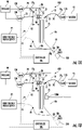
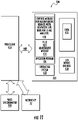
- the controller 100c can include at least one processor that can be configured to direct the system 100 to operate with a sequence of operations, such as a sequence of voltage and/or pressure inputs to components of the fluidic device 10.
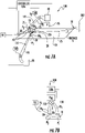
- the fluidic device 10 can be a microchip 10c.
- the fluidic device 10 can include at least one separation channel 25 (which can also be interchangeably referred to as a capillary channel) and at least one solid phase extraction (SPE) bed 28 in fluid communication with the separation channel 25.
- SPE solid phase extraction
- the SPE bed 28 can reside in a side channel 31 that connects to an upstream, upper end portion or ingress end portion 25u of the separation channel 25.
- the side channel 31 can be orthogonal to the separation channel 35 or may reside at other angles ( see, e.g. , Figure 4D ).
- the SPE bed 28 can reside between the separation channel 25 and a reservoir 30.
- the reservoir 30 can be configured to supply defined fluids, such as a sample fluid for analysis, to the SPE bed 28 , which flows over or through the SPE bed 28 , then to the separation channel 25 .
- the SPE bed 28 can be pre-packed or formed prior to an analysis, such as provided in a device ready for use, or may be packed in situ prior to and/or as part of an analysis.
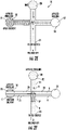
- the fluidic channel 31 holding at least one SPE bed 28 can include at least one blocking member 128 , such as a weir 128, or membrane.
- the blocking member 128 can be other fluid permeable, which may be particularly suitable for embodiments where the blocking member 128 extends totally across the sample inlet channel 31 .
- the blocking member 128 is configured to allow fluid, such as a liquid or gas sample S to flow through or over the SPE bed 28 while inhibiting SPE material from the bed 28 from entering the separation channel 25 .
- the term "weir" refers to structures with an obstruction across a width or partial width of the sample inlet channel 31 .
- the blocking member 128 resides between the end of the SPE bed 28e and the separation channel 25 , typically adjacent the separation channel, such as, for example, within about 10 ⁇ m to under 5 cm, typically between 10 ⁇ m to about 500 ⁇ m, and more typically between about 50 ⁇ m to about 500 ⁇ m from the separation channel 25.
- the side channel 31 (which can also be referred to interchangeably as "a sample inlet channel”) can be configured to have separate segments that merge into the sample inlet channel with the at least one blocking member 128. If so, separate reservoirs 30 1 , 30 2 may connect to a different branch 31a, 31b.
- the branches 31a, 31b can fluidly merge into the channel 31.
- One reservoir 30 1 can comprise the sample S and another 30 2 can hold SPE material 28s and/or other fluids for processing (e.g., wash or solvent and the like).
- Each branch/reservoir pair 30 1 /31b , 30 2 /31a can serially flowably introduce material to the inlet side channel 31.
- the blocking member 128 can extend down from the ceiling 31c ( 128 1 , Figure 6B ) or up from the floor 31f ( Figures 2B , 6F) and/or extend inwardly from sidewalls 31s ( Figures 6D , 6E).
- the at least one blocking member 128 can have a height that is less than a depth dimension of the channel 31 , typically between about 30-70% of the depth dimension.
- the height of the blocking member 128 can be between 30 and 70 ⁇ m, such as about 30 ⁇ m, about 40 ⁇ m, about 50 ⁇ m, about 60 ⁇ m, and about 70 ⁇ m.
- the two can be offset yet closely spaced apart (typically between about 1-20 ⁇ m) from each other.
- at least two of the blocking members 128 1 , 128 2 can be directly aligned from each other as shown in Figure 6C .
- Figures 6D-6F illustrate examples of sample channel geometries which may be formed by etching, milling, molding and the like.
- the number and placement of the at least one blocking member 128 are by way of illustration only.
- the fluidic device 10 comprises a planar rigid, semirigid or flexible (polymeric) ceiling 10c that is sealably attached to a substrate 10s holding the fluid channels 21, 25, 31, 32, typically in multiple sets, to seal the fluid channels.
- the blocking member(s) 128 can be integrally formed in the sample inlet channel 31 or be attached as a separate component, where more than one are used combinations of integral and separate components can be used.
- the SPE bed 28 can comprise any suitable solid phase extraction material and/or sorbent including mixtures of different materials.
- the SPE bed 28 can comprise, for example, small particles having a diameter and/or a maximal height/width or length dimension that is less, typically at least 30% less, than the width/depth of the fluidic channel 31 holding the bed 28.
- the SPE bed 28 can comprise 5 ⁇ m diameter porous Oasis HLB particles.
- Other particle types suitable for SPE beds 28 include, but are not limited to, reverse phase, ion exchange, immuno sorbent, HILIC, normal phase and mixed mode.
- An example of mixed mode is Water's Oasis HLB particles. A few examples of each type (to be clear this is not an exhaustive list) are provided below.
- the SPE material for the SPE bed 28 can include a retentive reversed-phase material and/or a mixed mode stationary phase, such as a combined reversed-phase retention with ion exchange retention. See, e.g., Gilar et al., Journal of Chromatography A 2008, 1191, 162-170 ; and Li et al., Talanta 2015, 140, 45-51 .
- the SPE bed 28 can have any suitable size, density and volume.
- the length of the SPE bed 28 can be between 1 ⁇ m and 1 cm, typically between 100 ⁇ m and 1000 ⁇ m, such as about 100 ⁇ m, about 200 ⁇ m, about 300 ⁇ m, about 400 ⁇ m, about 500 ⁇ m, about 600 ⁇ m, about 700 ⁇ m, about 800 ⁇ m, about 900 ⁇ m and about 1000 ⁇ m long.
- the length of the SPE bed 28 can be less than the fluidic channel 31 in which it resides, typically between 2-1000X less.
- the SPE bed 28 typically resides closer to separation channel 25 than the reservoir 30.
- the leading end (the end closest the separation channel 25 ) of the SPE bed 28 can reside within about 10 ⁇ m to under 5 cm, typically between 10 ⁇ m to about500 ⁇ m, and more typically between about 50 ⁇ m to about 500 ⁇ m from the entry or boundary of the separation channel 25 .
- the width of the fluid channel 31 holding the SPE bed 28 can be greater than the depth, typically 2-200X greater.
- the volume of a (packed) SPE bed 28 can be between about 50 pL to about 10 nL, such as about 425 pL, in some embodiments.
- the SPE bed 28 can be packed in the sample channel 31 prior to analysis of a sample S .
- An SPE slurry can be flowably introduced into the sample channel 31.
- the term "slurry" refers to a viscous solution of SPE material. The viscosity of the SPE slurry is greater than the viscosity of other liquids used for the analysis.
- a low concentration of an ion-pairing agent such as Trifluoroacetic acid (TFA) can be introduced into the fluid channel 31 and the SPE bed 28 to retain a sample S .
- TFA Trifluoroacetic acid
- This agent can be introduced before and/or with the introduction of a sample into the channel 31 .
- the TFA can be removed (e.g., washed into the waste channel 32 and/or waste reservoir 35 ) prior to elution for introducing the sample as a sample plug in the separation channel.
- Ion-Pairing agent current used in chromatography may be used for SPE with this device, depending on the chemistry of the SPE sorbent and the identity of the sample.
- Ion-exchange chromatography systems have previously been utilized in HPLC analysis of ionic samples including phase partition chromatography using ion-pair reagents.
- the ionic samples form an ion-pair with ion-pair reagents in the mobile phase to become electrically neutral.
- the increase in hydrophobic character of the ion-pair results in a greater affinity for the reverse stationary phase and leads to sample resolution.
- Acidic Sample R-COO - + R' 4 N + ⁇ R-COO - + NR' 4 Basic Sample See, e.g., the below webpage with different examples of ion-pairing agents: http://www.tcichemicals.com/eshop/en/us/category_index/00418/#innerlink_10_1_1.
- the ion-pairing agent can be pre-loaded into the fluid channel 31 (or onto the material of the SPE bed 28 ) or added in situ during or just prior to an analysis, for example.
- the system 100 can include a voltage supply 95, which may be a high voltage supply. As shown, the system 100 can also include at least one pressurized gas source 90 in communication with the BGE reservoir 20 and the side reservoir 30 via supply lines/conduits 70 and respective valves 120 , 130.
- the BGE reservoir 20 can feed a BGE channel 21 that is connected to the separation channel 25.
- the system 100 can include a pressure reducing device 91 in communication with a waste reservoir 35 which may also be connected via a respective valve 135.
- the pressure-reducing device 91 can have an active or passive configuration, i.e., can comprise a vacuum, a pump, an evacuated reservoir, or any other enclosed volume at a pressure less than the pressure applied to the BGE reservoir 20 and/or the side reservoir 30 , typically less than ambient pressure, that will reduce the pressure in the headspace of the waste reservoir 35 once connected.
- the pressure reducing device 91 can be configured with a supply line 70 to connect the waste reservoir 35 to the first pressurized gas source 90 and pressure can be controlled to provide the desired input. Also, the pressure reducing device 91 is not required to be a vacuum and may operate at different pressures to provide the desired operational sequence as will be discussed further below.
- the waste reservoir 35 is in fluid communication with the separation channel 25 .
- the waste reservoir 35 can reside in a second side channel 32 .
- the waste channel 32 can reside across from the side channel 31 with the SPE bed 28 .
- the waste channel 32 can be laterally in line with the side channel 31 (i.e., Figure 4A ) or can be longitudinally offset from the side channel 31 (i.e., Figure 4C ).
- the background electrolyte (BGE) reservoir 20 can reside at a top above the separation channel 25.
- the BGE reservoir 20 can reside directly adjacent the separation channel or may have a BGE flow channel 21 that merges into the separation channel 25 to position the BGE reservoir 20 a distance away from the sample channel 31 and the sample waste channel 32.
- the fluidic device 10 has cross channels defined by the sample channel 31 and the sample waste channel 32, which can reside on opposing sides of the separation channel 25 and may optionally be orthogonal to and extend across to intersect the separation channel 25 .
- defined pressures can be supplied by the pressurized gas supply 90 and/or 91 to the respective gas supply lines 70 which are sealably attached to respective reservoirs 20, 30, 35, typically conduits or lengths of tubing 70 from at least one pressurized gas source 90.
- the pressurized gas of the gas supply 90 for providing pressure-driven injection can comprise air and/or noble gases such as helium or nitrogen or other inert gases.
- Figure 1A illustrates discrete valves 120, 130, 135 for the gas supply lines 70 2 , 70 1 , 70 3 respectively. Any or all of valves 120, 130, 135 can be three-way valves.
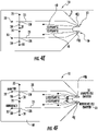
- Figure 1A also illustrates that the fluidic device 10 can include a pump 40 and at least one electrospray ionization (ESI) emitter 50 that can spray a separated sample 50s for analysis.
- the pump 40 can include a channel 40c that extends to a junction 40j adjacent the ESI emitter 50.
- the electrospray 50s from the at least one emitter 50 can be provided to a collection device 202 ( Figure 7A ) for subsequent analysis and/or toward an entrance aperture/inlet of a mass spectrometer 200 with a detector ( Figure 1A ).
- the pump can optionally comprise an electroosmotic (EO) pump.
- EO electroosmotic
- Figure 1B illustrates that the analysis system 100 can include the fluidic device 10 with the at least one SPE bed 28 and may also include at least one detector 1200 to obtain signal from the sample in the separation channel 25.
- the fluidic device 10 may be configured without the at least one ESI emitter 50 and may be used without requiring the input to the mass spectrometer 200.
- the detector 1200 can be an electronic detector such as an optical detector and/or a conductance detector (i.e., comprising an ammeter), for example. Where used, the optical detector 1200 can comprise an avalanche photodiode and laser, or photomultiplier and convention light source such as a blackbody source or discharge source, or any combination of the above as is well known to those of skill in the art.
- the detector 1200 can obtain signal for qualitative and/or quantitative data of a sample in the separation channel 25.
- the analysis system 100 can include both the at least one detector 1200 and the at least one ESI emitter 50 for input to the inlet/entrance aperture of the mass spectrometer 200.
- both mass spectrometer detection and optical detection by the detector 1200 can be carried out simultaneously, i.e., signal from the ESI emitter 50 the inlet of the mass spectrometer 200 can be obtained while signal from the detector 1200 is obtained for a respective sample, for example.
- the separation channel 25 is shown in Figures 1A and 1B as having a serpentine shape but other configurations may be used.
- the geometry of the separation channel 25 can be straight or curved, and the cross-sectional profiles of the channels do not all have to be the same.
- exemplary microfluidic devices see, e.g., U.S. Patent Application Serial Numbers 14/001,549 and 14/368,971 .
- the fluidic (sample) channel 31 holding the SPE bed 28 can have a width and/or depth that is between 40 nm and 1000 ⁇ m, more typically between about 1 ⁇ m and about 100 ⁇ m, such as a channel depth and width of about 10 ⁇ m (depth) and 70 ⁇ m (width), respectively.
- the "width" of channel 31 is measured in the plane of device 10 (i.e., in the plane defined by the microfluidic chip) and in a direction that is perpendicular to an axis of channel 31 , where fluid flow occurs through channel 31 in a direction parallel to the axis.
- the "depth" of channel 31 is measured in a direction perpendicular to the plane of device 10 and to the direction along which the width is measured.
- the fluidic channels 21 , 31 and 32 can all have the same depth or may have different depths.
- the fluidic channels 21 , 31 and 32 can have the same width or different widths.
- the separation channel 25 can have any suitable length, typically between 1 cm to 100 cm, more typically between about 20-30 cm, such as about 23 cm.
- the sample channel 31 is valveless so that the SPE bed 28 remains in fluid communication with the separation channel 25 continuously, i.e. , the fluid device 10 does not require any valve to isolate the SPE bed 28 from the separation channel 25.
- the at least one SPE bed 28 is held in the sample channel 31 and in the sample flow path without requiring any valve to isolate the SPE bed 28 during in-line operation.
- the BGE reservoir 20 can be at the top of the separation channel 25 (directly or via the BGE channel 21 ).
- the BGE channel 21 can have a length "L 1 " ( Figures 1A, 1B ) extending from the BGE reservoir 20 to the SPE bed channel 31 (which can also be called the “sample channel” as the sample is introduced into this channel to contact the SPE bed 28 prior to entering the separation channel 25 ) and/or the channel 31 and waste channel 32 cross/intersection with the separation channel 25 .
- the length "L 1 " can be any suitable length, such as, for example, between 1-200 mm long.
- the SPE bed channel 31 can have a length "L 2 " ( Figures 1A, 1B ) and the waste channel 32 can have a length "L 3 " ( Figures 1A, 1B ).
- the lengths L 1 , L 2 , L 3 of one or more of the channels 21, 31, 32 can be any suitable length such as about 1 mm, about 5 mm, about 10 mm, about 20 mm, about 30 mm, about 40 mm, about 50 mm, about 60 mm, about 70 mm, about 80 mm, about 90 mm, or about 100 mm, in some embodiments, but other lengths can be used.
- the "length" of a channel is measured along an axis of the channel in a plane of device 10 (i.e., in the plane defined by the microfluidic chip), where fluid flow occurs through the channel in a direction parallel to the axis.
- the injection cross configuration may be such that channels 21, 31 and 32 have substantially the same length or different lengths, but typically lengths that are much less than the length of the separation channel 25.
- the sample and sample waste channels 31, 32 can be longer or shorter than the BGE channel 21 and may, for example, be between 1 mm and 5 cm, typically between about 1-100 mm long. In some embodiments, the sample and sample waste channels 31, 32 are between about 1-20 mm, such as about 8 mm in length.
- One or both of the reservoirs 20, 30 can be in fluid communication with one or more external fluid sources to provide fluid thereto during analysis and/or one or both of the reservoirs 20, 30 may be pre-loaded prior to active analysis.
- a fluid junction 40j can be used to connect the separation/transfer channel 25 and respective pump channel 40c.
- the fluid junctions can be nanojunctions with the associated nanojunction channels having nanometer-sized depths.
- the pump channel 40c and/or separation channel 25 can have micrometer-sized widths.
- the junctions 40j can have, for example, a depth of about 50 nm and a width of about 50 ⁇ m. The depth of the channel may be dictated by the ionic strength of the buffers used in the experiment/analysis and the corresponding Debye lengths. Nanochannel depth should be on the order of the Debye length or smaller.
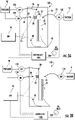
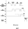
- Figures 2A-2H and 3A-3F illustrate an exemplary sequence of operations that can be carried out according to some embodiments of the present invention.
- Figures 2A and 2B show that a fluidic device 10 can be provided and a SPE bed 28 can be loaded or pre-loaded for use.
- Figure 2B shows the fluidic channel 31 with the SPE bed 28.
- Figures 2C and 3A illustrate a pre-conditioning of the SPE bed 28 can be carried out.
- Figure 2C shows a pre-conditioning fluid P such as a solvent from the reservoir 30.
- Figures 2C and 3A illustrate a pressure driving input P1 applied to the reservoir 30 while a pressure reducing device applies a reduced pressure such as a vacuum V1 to the waste reservoir 35 and voltage is OFF.
- Figure 3A illustrates the valves 130 and 135 are ON while valve 120 is OFF and the voltage is OFF (i.e., not applied to inputs 20 or 40 ). While the pressure is shown as OFF for valve 120 /pressure input to reservoir 20 , a pressure may be applied but not sufficient to interfere with the operational inputs.
- the pre-conditioning fluid P from the reservoir 30 flows across/through the SPE bed 28 and into the waste channel 32 , then to the waste reservoir 35.
- BGE solution B can flow from the BGE reservoir 20 .
- the flow direction of the pre-conditioning fluid P and BGE fluid B are indicated by the flow direction arrows in Figure 2C .
- pre-condition refers to exposing the SPE bed 28 to any solvent or liquid mixture of an appropriate organic content, pH, and/or salt content.
- the pre-conditioning agent or mixture may change based on the chemistry of the SPE sorbent and the identity of the sample S.
- the pre-conditioning material can be a defined liquid that can: optionally a) wet the SPE bed (although this is less of a concern with the microchip if the bed has been wetted during the chip filling step) and/or b) condition the SPE bed 28 to be in a desired current solvent condition that is suitable/appropriate for binding the target sample S. For example, in reversed phase SPE, loading can occur under low organic conditions.
- the pre-conditioning step can be used to ensure that the SPE bed 28 is wetted or exposed to low organic solvent.
- loading using a HILIC stationary phase occurs under high organic conditions.
- Loading with ion-exchange may occur under low salt, while elution occurs at high salt.
- pH can also affect loading and elution.
- FIGs 2D and 3B illustrate a sample loading step where sample S is introduced via reservoir 30 into the fluidic channel 31 with the SPE bed 28 . While the device 10 shows the sample S introduced via the same reservoir 30 as the pre-conditioning material, a separate reservoir can be used (not shown).
- the sample loading can be carried out using only pressure inputs such as an applied pressure P1 and a reduced pressure such as a vacuum V1 , with voltage OFF.
- Figure 3B illustrates the valves 130 and 135 are ON while valve 120 is OFF (closed to supply line 70 into reservoir 20 ) and the voltage is OFF (i.e., not applied to inputs 20 or 40 ).
- FIGs 2E and 3C illustrate an optional wash step where pressure P1 is applied to the reservoir 30 (or another reservoir in fluid communication with channel 31 ) and a lower pressure, typically a vacuum V1 , is applied to the waste reservoir 35 , with voltage OFF, to introduce a wash solvent to the fluidic channel 31 across the SPE bed 28 and into the waste reservoir 35.
- Figure 3C illustrates the valves 130 and 135 are ON while valve 120 is OFF and the voltage is OFF (i.e., not applied to inputs 20 or 40 ).
- the wash fluid can vary based on the chemistry of the SPE sorbent and the identity of the analyte(s).
- the purpose of the wash fluid is to displace the salt and any unbound species without unduly affecting the retention of the analyte(s) of interest.
- a low organic solution can be used to wash the sample S.
- the wash solvent and the loading solvent can be the same.
- the washing fluid can change based on different mechanisms, HILIC, ion-exchange, and the like as is well known to those of skill in the art.
- FIGs 2F and 3D illustrate an elution operation that can be carried out after the washing and/or sample loading step to distribute a sample plug Sp into the separation channel 25.
- Pressure P1 is applied to the reservoir 30 with an elution fluid E while pressure P2 is also applied to the BGE reservoir 20 and no reduced pressure such as a vacuum is required to be applied to the waste reservoir 35 (i.e., no vacuum is applied but a positive pressure may be applied to help keep the sample plug Sp in the separation channel 25 ).
- Figure 3D illustrates the valves 120 and 130 are ON while valve 135 is OFF and the voltage is OFF (i.e., not applied to inputs 20 or 40 ).
- the elution fluid E forces the sample plug Sp into the separation channel 25 and may flow into the waste channel 32 as indicated by Figure 2F .
- the elution material E can comprise high or low organic content.
- low organic content refers to an elution material in which organic analyte substances collectively comprise 25% or less of the volume of the elution material
- high organic content refers to an elution material in which organic analyte substances collectively comprise more than 25% by volume of the elution material.
- the elution material E can comprise high or low salt content.
- low salt content refers to an elution material in which a concentration of dissolved salts is between 0 - 0.1 M
- high salt content refers to an elution material in which a concentration of dissolved salts is above 0.1 M, such as above 0.1 M to about 1 M.
- the elution material E can have high or low pH.
- low pH refers to acidic pH levels (below 7)
- high pH refers to basic pH levels (above 7).
- the elution material E can comprise a combination of salts, and organic analyte substances, and the organic content and salt content can each be high or low, independent of the other. Further, the elution material can have a high or low pH, independent of the salt and organic content.
- the elution material may be an agent that disrupts the affinity binding, such as an analog of the sample with a higher binding affinity for the sorbent material.
- the elution and/or tITP material can be introduced via the BGE reservoir and channel 20/21 and/or via the sample channel 31 and a reservoir in fluid communication therewith.
- FIGs 2G and 3E illustrate an optional clearing operation that can be used according to embodiments of the present invention.
- Pressure input P1 can be reduced or removed while pressure input P2 is applied to the BGE reservoir 20 , with voltage OFF.
- Pressure input to the waste reservoir 35 can also be reduced or removed so that BGE fluid flows down to push the sample plug Sp past the fluidic channel 31 with the SPE bed 28.
- the BGE fluid can push the elution fluid E to exit the SPE bed 28 toward the reservoir 30.
- Figure 3E illustrates the valve 120 is ON while valves 130 and 135 are OFF and the voltage is OFF (i.e., not applied to inputs 20 or 40 ).
- Figures 2H and 3F illustrate that a subsequent transport/ separation between successive sample plugs Sp can be carried out by applying voltage to the BGE reservoir 20 and to the ESI orifice without applying pressure to reservoir 30 or 35.
- the applied voltage can be high voltage at reservoir 20 and a positive voltage at the ESI orifice (e.g., at EO pump input 40 ) to drive the sample plug Sp to the ESI emitter orifice 50.
- Figure 3F illustrates the valves 120, 130 and 135 are OFF and the voltage is ON (i.e., applied to inputs 20 or 40 ).
- the term "high voltage” refers to voltage in the kV range, typically between about 1-100 kV, more typically between about 1-20 kV.
- ESI processes can employ potentials of a few kVs, typically between about 1kV to about 5 kV, for example. Other voltages may be appropriate.
- pressure can be used to inject samples of a microfluidic device 10 for microchip capillary electrophoresis (CE).
- the pressure-drive method has advantages over other microfluidic injection methods such as voltage-driven loading methods, in that it can use a simple channel geometry, but is capable of generating desired sample plug Sp sizes ( Figures 2F , 2G, 2H ) by simply adjusting the time the pressure is applied and/or the amount of pressure applied to the reservoirs 20, 30.
- the pressure-drive operation is also typically free of eletrokinetic injection bias and no voltage is required to be applied to the sample reservoir 30.
- the pressure applied concurrently to the BGE reservoir 20 and the sample reservoir 30 for the injection is between 1 and 30 psi for between 1-5 seconds, more typically between 1 and 12 psi.
- the pressure P2 in the BGE reservoir 20 can be held the same or reduced by 10-80% and the pressure in the reservoir 30 can be reduced more than the reduction in the pressure of the BGE reservoir 20 , e.g., typically so that it is less than 0.1 psi, e.g., zero or at ambient or atmospheric pressure or below ambient or atmospheric pressure (e.g., under vacuum).
- the term "reduced" with respect to pressure can also include removing the applied pressure altogether.
- the clearing pressure on the BGE reservoir 20 can be held for a time that is less than the injection time where pressure is applied to both reservoirs 20, 30 ( Figure 2F , 3D).
- the clearing time for the pressure applied only to the BGE reservoir 20 can be 2 seconds or less, 1 second or less or 0.5 seconds, for example.
- pressure-driven methods can be particularly suitable for performing online sample concentration methods such as transient isotachophoresis (tITP), because sample plugs Sp with significantly different properties (electrical conductivity, pH, or viscosity) compared to the background electrolyte (BGE) can be injected. Salt or other electrolyte material in the sample/sample reservoir 30 can be used for tITP.
- the pressure-driven operation can position a well-defined band of sample (sample plug Sp ) into the separation channel 25 of the microfluidic device using only pressure-driven flow and can also be used for online sample focusing methods that are not possible by other microfluidic injection methods.
- head pressure can be applied to two different fluid reservoirs 20 , 30 and/or 35 on or in communication with the microfluidic device 10 , typically using off-device (e.g., off-chip) on/off valves 120 , 130 , 135 .
- the term "head pressure" refers to the gas pressure in a sealed headspace of the reservoir above the liquid.
- the head pressure of the BGE reservoir 20 is labeled P2 and the head pressure of the sample reservoir 30 is labeled P1.
- a controller 100c can be in communication with the valves 120, 130, 135 to independently control when the pressures P1, P2 and V1 are applied at the respective reservoirs 20, 30, 35.
- no voltage is required to be applied to either the BGE reservoir 20 or the sample reservoir 30 ( Figures 2D , 2F , 2G , for example).
- microfluidic channels 25, 31, 32 within the device 10 can, in some embodiments, be configured to form a simple injection cross.
- the sample waste channel 32 may be excluded as shown in Figure 4B , for example.
- the use of a "tee" intersection of the sample channel 31 (in lieu of the cross channel configuration) to the separation channel 25 may be used and may be implemented using a relatively precise pressure on the BGE reservoir 20 to hold that fluid stationary for injection/sample loading, at least where EK drive is not employed.
- pressure is concurrently applied to the sample reservoir 30 (PI) and the BGE reservoir 20 (P2) to drive sample S from the sample reservoir 30 (shown by the directional arrows) into the separation channel 25 from the sample channel 31 , and typically the sample waste channel 32 , but not the BGE channel 21 .
- a plug of a sample Sp in the separation channel 25 reaches a desired length (typically downstream of both the BGE reservoir 20 and the sample reservoir 30 )
- pressure is decreased or released from the sample reservoir 30 , but pressure is kept on at the BGE reservoir 20 .
- flow from the BGE channel 21 clears sample in the sample and waste channels 31, 32 , leaving a defined plug of sample Sp (trailing end is separated from any adjacent sample in the cross channels 31, 32 ) in the primary fluid transport (e.g., separation) channel 25 .
- This pressure drive/injection is carried out without requiring any voltage input to the sample reservoir 30.
- the pressure is released from the BGE reservoir 20 and voltage is applied between the BGE reservoir 20 and the separation channel 25 at a downstream location, typically an end portion or terminus of the separation channel 25 such as at EO input 40 to perform an electrophoretic separation.
- the voltage applied to the BGE reservoir 20 can be a high voltage HV, although lower voltages may be used in some embodiments.
- the voltage V applied downstream can be a lower voltage than the voltage applied to the BGE reservoir 20.
- the lower voltage V can be any suitable EK driving voltage and may be between 10%-50% of the BGE reservoir voltage. Voltage can vary and typically ranges from about +1kV to +30 kV and the lower voltage might range from 0 to +4 kV. But, the voltages and polarity can vary for different applications.
- the polarity of the separation could be reversed so that the high voltage input shown in Figure 2H is negative, or closer to zero (0) and the opposing voltage (shown in Figure 2H as the "+V" input) could be higher or even negative depending on the relative length of the microfluidic channels, the charge of the analytes, and the polarity of the ESI process.
- Embodiments of the application refer to voltages that are referenced to a common ground or reference voltage with a value designated as "0" volts ("V").
- each of the sample reservoir 30 , the BGE reservoir 20 , and the waste reservoir 35 can be maintained at a common electrical potential as the sample is flowed through the sample channel using only pressure-driven operation so as to not apply an electrokinetic voltage, since these reservoirs are at the same electrical potential in the absence of an external field.
- the sample can be introduced into the separation channel 25 without applying an electrokinetic voltage and/or voltage gradient across the sample channel 31 and/or SPE bed 28.
- the sample can be flowed through the sample channel 31 without applying a voltage to the sample reservoir 30 , to the BGE reservoir 20 , or to the waste reservoir 35 and/or with no electric potential gradient in any of the sample channel 31, the BGE channel 21 and the waste channel 32.
- the pressures applied to the headspaces of the reservoirs 20 , 30 can be low pressures, typically between 0.1 psi and 50 psi, more typically between 0.5 and 30 psi, or between about 0.5 and about 12 psi or 10 psi (0.69 bars).
- the pressures can be about 0.5 psi, about 1 psi, about 1.5 psi, about 2 psi, about 2.5 psi, about 3 psi, about 3.5 psi, about 4 psi, about 4.5 psi, about 5 psi, about 5.5 psi, about 6 psi, about 6.5 psi, about 7 psi, about 8 psi, about 8.5 psi, about 9 psi, about 9.5 psi, about 10 psi, about 10.5 psi, about 11 psi, about 11.5 psi, about 12 psi.
- the reduced pressure such as a vacuum pressure applied to the waste reservoir 35 can be between about 1 psi and about 15 psi, typically between about 10 psi and 15 psi, such as 10 psi, 11 psi, 12 psi, 13 psi, 14 psi and 15 psi.
- tITP has been previously described as an online sample focusing method for capillary electrophoresis. This phenomenon works when the sample contains a relatively large concentration of an electrolyte (termed the leading electrolyte) that has higher electrophoretic mobility than the analyte ions. As is well known, the leading electrolyte is typically added to the sample solution. The leading electrolyte concentration should be significantly greater (such as at least 5X or 10X greater) than the electrolyte concentration in the background electrolyte to provide a sufficient minimum conductivity difference between the background electrolyte and the leading electrolyte. This is the situation that exists for the pressure-driven injection of samples with high concentration of sodium chloride or other defined electrolyte.
- the BGE reservoir 20 can include liquid electrolyte comprising sodium and/or salt in sufficient amount for tITP introduced through channel 21.
- the liquid electrolyte may optionally additionally or alternatively be introduced via another reservoir and channel, such as, via sample channel 31 or another side channel.
- This tITP can be carried out before the separation shown in Figures 2H , 3F to reduce band broadening that may otherwise be introduced during the transfer of the analyte sample from the SPE bed 28 to the separation channel 25 .
- Figures 4A-4F and 6A are non-limiting examples of microfluidic devices 10 that can be operated as described above.
- Figure 4A illustrates the fluidic channel 31 can include a plurality of spatially separated SPE beds 28 , shown as first and second SPE beds 28 1 , 28 2 . Where more than one SPE bed 28 is used they can comprise the same or different sorbents and have the same or different volumes and/or lengths.
- Figure 4B illustrates the microfluidic device 10 does not require a waste channel 32 or waste reservoir 35 (and this example does not fall under the scope of the appended claims).
- Figure 4C illustrates the waste channel 32 offset a longitudinal distance from the sample channel 31 across the separation channel 25.
- Figure 4D illustrates the device 10 can have a plurality of sample reservoirs 30 , shown by way of example as three, 30 1 , 30 2 , 30 3 , all or some of which can have the SPE bed 28 , but more or less than three may be used.
- the reservoirs 30 can feed a common or different sample channels 31 , shown as having different sample channels 31 1 , 31 2 , 31 3 all for a single separation channel 25 , and at least one BGE reservoir 20 (shown as a single BGE reservoir 20 and reservoir channel 21 ).
- the sample reservoirs 30 can be controlled to sequentially or serially be pressure-driven to inject respective sample plugs across the SPE bed 28 and into the separation channel 25.
- the devices 10 can also optionally have an EO pump 40.
- Figure 4E illustrates a microfluidic device 10 that can have a plurality of separation channels 25, shown as two adjacent channels, but more than two may be included on a single device 10.
- the separation channels 25 can feed a common or separate emitters 50 .
- the microfluidic device 10 can include more than one separation channel 25 and associated BGE reservoir 20 , reservoir 30 , SPE bed 28 , waste reservoir 35 and channels 31, 32 .
- One or more of the individual channels 21, 25, 31, 32 might be configured to have lateral dimensions of about 1-100 ⁇ m, e.g., about 75 ⁇ m, with lateral spaced apart dimensions of about 1-100 mm, in some particular embodiments.
- one or more reference channels for a reference spray may be included on/in the microfluidic device 10.
- the reference material for the reference spray from a respective ESI emitter 50 can provide one or more ions for internal calibration.
- the reference material provides a single defined ion for internal calibration.
- the reference material can include multiple ions over a desired range, typically that are over substantially an entire m/z range of interest, to improve the mass accuracy.
- Figure 5A is a schematic illustration of a BGE reservoir 20 having a gas-tight fitting holding a pressure supply line 70 and a (typically high) voltage line 75 with a high voltage input 75i (shown as a platinum wire) that extends inside the sealed reservoir 20 so as to be able to make contact with the fluid, e.g., liquid, in the reservoir 20.
- gas-tight means that the seal on the reservoir 20, 30 does not unduly leak when operated so as to be able to provide the desired pressure to the headspace 20h, 30h, 35h for pressure-driven injection.
- the pressure supply line 70 can be provided with tubing with an open pressurized gas path extending into the sealed headspace 20h.
- the pressure supply line can be tubing less than this size, e.g., 1/4 inch to about 1/16 inch outer diameter.
- larger size conduits can be used when stepped down in size for the supply into the reservoir head space under the sealed connection.
- the sealed (e.g., gas-tight) connection of a respective pressurized gas supply line 70 to either reservoir 20, 30 (and/or waste reservoir 35 ) can be provided via epoxy, O-ring, metal or elastomeric gaskets, grease fittings, and/or other suitable configurations.
- Figure 5B illustrates that the pressured gas supply line 70 can be held adjacent the high voltage cable 75 in a common sleeve 80. It is further noted that the high voltage cable 75 can be held routed into the headspace while held inside the gas supply tubing.
- Figure 5B also illustrates that the top of the reservoir 20t can be sealed with a cap 20c and a side port 20p can be used to attach the pressurized gas supply line 70 to the reservoir 20.
- the same arrangement can be used for the sample reservoir 30 and/or waste reservoir 35 (not shown).
- the gas supply line 70 can be attached over the outer wall of the wall 20w of the reservoir 20 instead of extending inside the reservoir 20 for gas-tight or sealed connection. Other connection configurations may be used.
- Figure 7A illustrates an example of a microfluidic system 100 which includes a controller 100c used to control operation of the pressure supply to the reservoirs 20, 30 to carry out a pressure-driven injection.
- the system 100 can include first and second pressurized gas supply lines or conduits 70 , shown as 70 1 , 70 2 , each in fluid communication with at least one valve 120, 130.
- the system 100 can include a three-way valve ( Figure 7B ) that closes and opens each supply line of the valves 120, 130.
- separate valves 120, 130, 135 are used for each supply line 70 1 , 70 2 (and 70 3 ).
- One or all of the valves 120 , 130, 135 can be a three-way valve (e.g., three way operation, open/close to source, open/close to head space and open/close to atmosphere) for a respective supply line 70 which can allow for the rapid venting of pressurized gas from a respective supply line.
- a three-way valve e.g., three way operation, open/close to source, open/close to head space and open/close to atmosphere
- one or both of the valves 120 , 130, 135 can be operated to vent the head pressure in the reservoir 20 , 30 , to atmosphere, which may help precisely control the injection process.
- One or both of the gas supply lines 70 and/or reservoirs 20, 30, 35 can also or alternatively include vents 121, 131 ( Figure 7A ) that can be electronically opened and closed, for rapid venting to atmosphere to decrease pressure in a respective headspace 20h, 30h.
- the term "rapid" with respect to the venting or pressure reduction (e.g., venting to atmosphere) in a respective pressure supply line 70 refers to a drop in pressure of the corresponding headspace 20h, 30h, 35h of a respective reservoir 20 , 30 and 35 to at least atmospheric pressure within 0.1-3 seconds, more typically within about 2 seconds or within about 1 second.
- the rapid venting can be based on a control signal from the controller 100c that (a) directs the valve 120 or 130 or 135 to open to atmosphere (where a three-way valve is used) or (b) opens a vent separate from the valve 120 , 130, 135 and closes the valve 120 , 130, 135.
- the rapid pressure reduction can be measured by a pressure sensor in the supply line or reservoir to indicate the rapid drop in head pressure from an operative pressure to atmospheric pressure within a 0.1-2 second time period.
- the rapid venting can be carried out in between about 0.1 seconds and 1.5 seconds, such as about 0.1 seconds, about 0.2 seconds, about 0.3 seconds, about 0.4 seconds, about 0.5 seconds, about 0.6 seconds, about 0.7 seconds, about 0.8 seconds, about 0.9 seconds, about 1 second, about 1.1 seconds, about 1.2 seconds, about 1.25 seconds, about 1.5 seconds, about 2 seconds, and about 2.5 seconds.
- the first and second pressurized gas supply lines 70 1 , 70 2 can each be in communication with a common pressurized gas source 90 or each may have its own pressurized gas source.
- the system 100 can include a power supply 95 for the high voltage input to the microfluidic device 10.
- the power supply 95 can be attached to the cable 75.
- the controller 100c can direct the timing sequence of the differentially applied pressure to the microfluidic device.
- the controller 100c can be in communication with the valves 120, 130 , 135 the at least one pressure source 90 (and a pressure reducing device 91 , where used) and the power supply 95.
- the term "controller” is used broadly to include a single or multiple processors or application specific integrated circuit (ASIC) held on or in communication with a single device, e.g., the microfluidic device 10 , and/or computer, laptop, notebook, smartphone and the like, or distributed in different devices using wires or wireless connections including local area networks or wide area networks, e.g., the internet, including any server system.
- ASIC application specific integrated circuit
- the controller 100c can direct the valves 120, 130, 135 to open and close to carry out successive sample injections using a defined sequence, an example of which is shown in the timing chart of Figure 8 .
- the SPE can be packed before the sample is loaded.
- the packing can be carried out using a reduced pressure (relative to pressure applied to the other reservoirs) such as a vacuum V1 applied to the waste reservoir 35 with or without pressure applied to either the sample channel 31 or BGE channel 21 , typically without such other pressures.
- the packing of the SPE bed can be carried out using a defined pressure for a defined time, typically between 1-10 minutes. Pressures P1 , V1 can be applied for a defined time that is typically less than the packing duration.
- the sample can be loaded using the pressures PI, VI, typically for a duration that less than the packing time, such as between 30-50% of the packing time and/or between 1-8 minutes.
- Pressure P2 can then be applied concurrent with pressure P1 to inject the sample plug into the separation channel 25.
- the electric field can be applied to separate the sample plug and spray the sample toward an inlet of an MS.
- the broken line shown for P2 illustrates that this pressure can be ON (typically at the same or a lesser amount as for the separation pressure).
- the SPE bed can be pre-conditioned for a short time, typically between about 10 seconds to about 1 minute before the loading of the sample using V1 and P1 as shown.
- the elution can include applying a short duration (i.e., 0.1-1 second) of pressures V1 , P1 followed by a longer duration of pressures P1 and P2 for the injection/sample plug delivery to the separation channel.
- V1 may be OFF or ON during the elution delivery.
- electrophoretic separation voltage can be applied concurrently with or just after pressure P2 is removed or decreased from the BGE reservoir 20.
- sample injection is carried out using only pressure P2 applied to the BGE reservoir and only pressure P1 applied to the sample reservoir from the first and second supply lines 70 (e.g., tubes or conduits) without any electrokinetic (EK) voltage.
- Voltage can be applied to the BGE reservoir 20 after the injection for the ESI emitter spray 50s.
- the controller 100c can be configured to operate the fluidic device 10 using a defined timing sequence for applying defined pressures (headspace pressures) between 0.1 and 30 psi to a headspace 20h of the BGE reservoir 20 via the supply tube 70 2 and to a headspace 30h of the sample reservoir 30 via the supply tube 70 1 for defined durations, typically between 1 and 10 seconds, to inject a sample into the separation channel 25.
- defined pressures headspace pressures
- the timing chart shown in Figure 8 is by way of example and the noted "zero" pressures of P1 (for the sample reservoir 30 ) and P2 (for the BGE reservoir 20 ) may be atmospheric or ambient pressures or may alternatively be vacuum pressures.
- the applied voltage V from the power supply 95 to the input 75i in the BGE reservoir 20 can have a shorter or longer duration than the concurrent injection pressures PI, P2 ( Figure 2F ) or the subsequent "clearing" pressure P2 ( Figure 2G ) .
- the P2 pressure can remain constant or change, typically decreasing, from the concurrent pressure for injection to the "clearing" pressure when P1 is “OFF” or substantially decreased ( Figure 2G ) .
- the fluidic device 10 can be a microfluidic chip that has a substrate 10s and/or ceiling 10c that is formed of hard or substantially rigid materials that include, but are not limited to, substrates comprising one or combinations of: glass, quartz, silicon, ceramic, silicon nitride, polycarbonate, and polymethylmethacrylate.
- the device 10 can include a glass substrate such as a borosilicate.
- a rigid polymer material may be used to form the microfluidic device.
- the device 10 can also include one or more layers of a soft or flexible substrate. Soft substrate materials, where used, can have a low Young's Modulus value.
- elastomers and harder plastics and/or polymers can have a range between about 0.1-3000 MPa.
- soft materials include, but are not limited to, polydimethylsiloxane (PDMS), polymethylmethacrylate (PMMA), and polyurethane.
- PDMS polydimethylsiloxane
- PMMA polymethylmethacrylate
- polyurethane See, e.g., co-pending PCT/US2012/027662 filed March 5, 2012 and PCT/US2011/052127 filed September 19, 2011 for a description of examples of microfabricated fluidic devices. See , also , Mellors, J. S.; Gorbounov, V.; Ramsey, R. S.; Ramsey, J.
- EO pumps can be integrated on a microfluidic device 10 for electrospray ionization via implementations other than the examples shown in Figures 4A-4F .
- two channels intersect at a junction, which may be a T-like junction (not restricted to a right angle intersection).
- a voltage is applied to two of the three resulting channel termini generating an axial electric field through the associated channel segments.
- the electroosmotic mobility in the two channel segments that contain the axial electric field is generally different in magnitude and/or sign.
- the difference in electroosmotic mobility can be achieved by chemically modifying one, or both, of the associated channel segments so as to produce different surface charge densities and hence different electroosmotic mobilities.
- Electroosmotic mobility can also be modified by coating a channel wall with electrically neutral polymer films, thereby increasing the effective fluid viscosity within the electrical double layer at the wall.
- Another way to modify electroosmotic mobility is reduce one of the channel lateral dimensions to distances similar in magnitude to the Debye length of the solution being electroosmotically pumped.
- the described methods for modifying electroosmotic mobility may also be used in combination where desired. Methods for electroosmotic pumping are further described in U.S. Patent 6,110,343 .
- electrical connection for producing the electrospray voltage can be achieved using a side channel similar to the EO pumping channel or by contacting the fluid using an electrode in a reservoir external to the microfluidic device, or in the case of using metal tubing between the device 10 and the pump, connection can be made to the tubing.
- Figure 9A illustrates a portable mass spectrometer 200 with a housing 201 holding at least one of the microfluidic devices 10 with an onboard controller 100c, a power supply for the voltage 95 , a pressurized gas supply 90 , a pressure reducing device 91 , a detector 205 , an analyzer 210 and an optional display 215 for providing output data.
- Figure 9B illustrates that the microfluidic device 10 can be in communication with a mass spectrometer 200 with an MS input 200i facing the ESI emitter 50 for receiving the spray 50s.
- the controller 100c can be separate or partially or totally onboard the mass spectrometer 200.
- Figure 10A is a flow chart of exemplary operations that can be used to carry out a sample analysis.
- a fluidic device is provided (block 270 ).
- the fluidic device has at least one separation channel, at least one BGE channel in fluid communication with the separation channel, at least one waste channel in fluid communication with the separation channel and at least one sample channel in fluid communication with the separation channel.
- the sample channel can have a pre-formed SPE bed therein.
- the SPE bed can be flowably formed in the sample channel (block 272 ).
- the SPE bed can be flowably formed by applying a reduced pressure via a pressure reducing device to the waste channel while applying a greater pressure to the sample channel to flow a slurry of SPE material into the sample channel until it hits at least one blocking member residing upstream of the separation channel to flowably form the SPE bed.
- the SPE bed can be pre-conditioned by flowing solvent across the SPE bed and into the waste channel (block 275 ).
- a low concentration of an ion-pairing agent such as TFA to retain a sample can be introduced before introducing the sample per block 280 and then the TFA can be removed prior to elution of block 285 (block 283 ).
- the sample can be flowed over/through at least one SPE bed in the sample channel toward the waste channel (block 280 ).
- Wash solvent can be flowed across the at least one SPE bed toward the waste channel after the same is flowed over the SPE bed (block 282 ).
- Elution fluid can then be flowed over/through the at least one SPE bed toward the waste channel to load a sample plug into the separation channel (block 285 ).
- BGE liquid can then be flowed into the separation channel a distance below/downstream of the waste and sample channels to clear the separation channel and adjacent waste and sample channels while moving the sample plug downstream of the waste and sample channels in the separation channel (block 288 ).
- tITP can be performed (using the BGE reservoir) prior to the CE separation of block 288 to narrow the injection band and reduce band broadening otherwise associated with transfer of the sample plug/band from the SPE bed to the separation channel (block 289 ).
- An electric field can be applied to the separation channel to separate adjacent plugs, forcing the sample plug to travel toward an ESI emitter and cause the ESI emitter to spray the sample (block 290 ).
- the sprayed sample can be analyzed in a mass spectrometer to determine information about the sample (block 295 ).
- the analysis can include detecting analyte peak signals of the sample using a mass spectrometer and generating electropherograms of the sample, for example.
- Electronic detection of signal of the separated sample in the separation channel can be obtained using a detector in communication with the separation channel (optically and/or electronically). This electronic detection can be carried out without the mass spectrometer detection or with the mass spectrometer detection. In some embodiments, the electronic detection by the detector is carried out simultaneously with detection by the mass spectrometer for a respective separated sample.
- the pre-conditioning, flowing and loading steps can be carried out using only a sequence of defined pressure inputs to the BGE channel, the sample channel and the waste channel without requiring electric fields until the separation and spray.
- FIG. 10B is a flow chart of exemplary operations that can be used to carry out a sample analysis.
- a microfluidic device is provided with at least one separation channel in fluid communication with a background electrolyte (BGE) reservoir and a sample reservoir and having a sample channel with an SPE bed; the sample channel merges into the separation channel (block 300 ).
- BGE background electrolyte
- a fluid sample is injected (flowably introduced) from the sample reservoir across the SPE bed into the separation channel downstream of the BGE reservoir by concurrently applying a defined pressure to the BGE reservoir and a defined pressure to the sample reservoir (block 310 ).
- a reduced pressure (optionally a vacuum) can be applied to a waste reservoir residing across from the sample channel during the injecting step.
- a trailing end of the sample plug is cleared from the sample channel using fluid flowed from the BGE reservoir to deliver the sample plug in the separation channel in response to reducing or removing the pressure applied to the sample reservoir while applying pressure to the BGE reservoir so that pressure applied to the BGE reservoir is greater than pressure then applied to the sample reservoir (block 320 ).
- the delivered sample is electrophoretically separated in the separation channel by applying an electric field to the separation channel, i.e., voltage to the BGE reservoir and a downstream location of the separation channel or proximate EO pump channel/input (block 330 ).
- the pressure in the BGE reservoir can be held constant, further reduced or removed while the voltage is applied.
- the injecting, clearing and electrophoretic separation can be carried out without applying a voltage to the sample reservoir (block 340 ).
- a duration of the pressure can be electronically adjusted or the pressure applied to the sample or BGE reservoir 20, 30 can be increased or decreased for the injecting and/or clearing to adjust a size of the plug of the sample delivered to the separation channel.
- the separated sample can be analyzed, optionally using a mass spectrometer to determine information about the sample (block 335 ).
- the analysis can include detecting analyte peak signals of the sample using a mass spectrometer and generating electropherograms of the sample, for example.
- the analysis can comprise electrical conductance detection and/or optical detection of the separated sample in the separation channel to obtain quantitative and/or qualitative data of the analytes in the sample.
- embodiments of the present invention may combine software, firmware and/or hardware aspects, all generally referred to herein as a "circuit” or “module.”
- the present invention may take the form of a computer program product on a computer-usable storage medium having computer-usable program code embodied in the medium. Any suitable computer readable medium may be utilized including hard disks, CD-ROMs, optical storage devices, a transmission media such as those supporting the Internet or an intranet, or magnetic storage devices. Some circuits, modules or routines may be written in assembly language or even micro-code to enhance performance and/or memory usage.
- program modules may also be implemented using discrete hardware components, one or more application specific integrated circuits (ASICs), or a programmed digital signal processor or microcontroller.
- ASICs application specific integrated circuits
- Embodiments of the present invention are not limited to a particular programming language.
- Computer program code for carrying out operations of the present invention may be written in an object oriented programming language such as Java ® , Smalltalk or C++.
- the computer program code for carrying out operations of the present invention may also be written in conventional procedural programming languages, such as the "C" programming language.
- the program code may execute entirely on the user's computer, partly on the user's computer, as a stand-alone software package, partly on the user's computer and partly on another computer, local and/or remote or entirely on the other local or remote computer.
- the other local or remote computer may be connected to the user's computer through a local area network (LAN) or a wide area network (WAN), or the connection may be made to an external computer (for example, through the Internet using an Internet Service Provider).
- LAN local area network
- WAN wide area network
- Internet Service Provider for example, AT&T, MCI, Sprint, EarthLink, MSN, GTE, etc.
- Embodiments of the present invention are described herein, in part, with reference to flowchart illustrations and/or block diagrams of methods, apparatus (systems) and computer program products according to embodiments of the invention. It will be understood that each block of the flowchart illustrations and/or block diagrams, and combinations of blocks in the flowchart illustrations and/or block diagrams, can be implemented by computer program instructions. These computer program instructions may be provided to a processor of a general purpose computer, special purpose computer, or other programmable data processing apparatus to produce a machine, such that the instructions, which execute via the processor of the computer or other programmable data processing apparatus, create means for implementing the functions/acts specified in the flowchart and/or block diagram block or blocks.
- These computer program instructions may also be stored in a computer-readable memory that can direct a computer or other programmable data processing apparatus to function in a particular manner, such that the instructions stored in the computer-readable memory produce an article of manufacture including instruction means which implement the function/act specified in the flowchart and/or block diagram block or blocks.
- the computer program instructions may also be loaded onto a computer or other programmable data processing apparatus to cause a series of operational steps to be performed on the computer or other programmable apparatus to produce a computer implemented process such that the instructions which execute on the computer or other programmable apparatus provide steps for implementing some or all of the functions/acts specified in the flowchart and/or block diagram block or blocks.
- each block in the flow charts or block diagrams represents a module, segment, or portion of code, which comprises one or more executable instructions for implementing the specified logical function(s).
- the functions noted in the blocks may occur out of the order noted in the figures. For example, two blocks shown in succession may in fact be executed substantially concurrently or the blocks may sometimes be executed in the reverse order or two or more blocks may be combined, or a block divided and performed separately, depending upon the functionality involved.
- FIG 11 is a schematic illustration of a circuit or data processing system 290.
- the system 290 can be used with microfluidic devices 10 and/or mass spectrometers 200.
- the circuits and/or data processing systems 290 may be incorporated in a digital signal processor in any suitable device or devices.
- the processor 410 can communicate with a mass spectrometer 200 and/or microfluidic device 10 and with memory 414 via an address/data bus 448.
- the processor 410 can reside in a control circuit or controller that is separate from the spectrometer 200 or that is integrated wholly or partially therein.
- the processor 410 can be any commercially available or custom microprocessor.
- the memory 414 is representative of the overall hierarchy of memory devices containing the software and data used to implement the functionality of the data processing system.
- the memory 414 can include, but is not limited to, the following types of devices: cache, ROM, PROM, EPROM, EEPROM, flash memory, SRAM, and DRAM
- Figure 11 illustrates that the memory 414 may include several categories of software and data used in the data processing system: the operating system 452 ; the application programs 454 ; the input/output (I/O) device drivers 458 ; and data 455 .
- the data 455 can include sample type, plug size adjustments for pressures, calibration data, time synchronization data (e.g., pressures/duration for loading/injection), and/or other detected or internal mass spectrometer data.
- the operating systems 452 may be any operating system suitable for use with a data processing system, such as OS/2, AIX, DOS, OS/390 or System390 from International Business Machines Corporation, Armonk, NY, Windows CE, Windows NT, Windows95, Windows98, Windows2000, WindowsXP or other Windows versions from Microsoft Corporation, Redmond, WA, Unix or Linux or FreeBSD, Palm OS from Palm, Inc., Mac OS from Apple Computer, LabView, or proprietary operating systems.
- the I/O device drivers 458 typically include software routines accessed through the operating system 452 by the application programs 454 to communicate with devices such as I/O data port(s), data storage 455 and certain memory 414 components.
- the application programs 454 are illustrative of the programs that implement the various features of the data (image) processing system and can include at least one application, which supports operations according to embodiments of the present invention.
- the data 455 represents the static and dynamic data used by the application programs 454 , the operating system 452 , the I/O device drivers 458 , and other software programs that may reside in the memory 414.
- Control Module for Microfluidic Devices with in-line SPE beds for CE-MS analysis of samples typically with a Pressure Input Sequence
- Plug Size (pressure/duration) Adjustment Module 451 being application programs in Figure 11 , as will be appreciated by those of skill in the art, other configurations may also be utilized while still benefiting from the teachings of the present invention.
- the Module 451 can allow for a user to select a desired injection time (Pressure ON time, OFF time, pressure for a respective injection and/or clearing and the like, for each reservoir).
- Modules 450 and/or 451 may also be incorporated into the operating system 452 , the I/O device drivers 458 or other such logical division of the data processing system. Thus, the present invention should not be construed as limited to the configuration of Figure 11 , which is intended to encompass any configuration capable of carrying out the operations described herein. Further, Module 450 and/or 451 can communicate with or be incorporated totally or partially in other components, such as a mass spectrometer 200 , power supply 95 , an interface/gateway or a computer such as at a workstation that may be local or remote from the microfluidic device/spectrometer.
- the I/O data port can be used to transfer information between the data processing system, the workstation, the spectrometer, the microfluidic device, the interface/gateway and another computer system or a network (e.g., the Internet) or to other devices or circuits controlled by the processor.
- These components may be conventional components such as those used in many conventional data processing systems, which may be configured in accordance with the present invention to operate as described herein.
- LC-MS grade acetonitrile, methanol, acetone, and formic acid (99.99%) were acquired from Fisher Chemical (Fairlawn, NJ) as well as HPLC grade ammonium acetate and trifluoroacetic acid (TFA) (99.975%).
- Water was purified with a Nanopure Diamond water purifier (Barnstead International, Dubuque, IA).
- APDIPES (3-Amino)di-isopropylethoxysilane (APDIPES) was acquired from Gelest (Morrisville, PA).
- Sodium phosphate dibasic, trichloro(1H,1H,2H,2H-perfluorooctyl)silane was acquired from Sigma-Aldrich (St.
- Met-enkephalin, bradykinin, angiotensin II, thymopentin, and human glu-fibrionpeptide were purchased from American Peptide Company (Sunnyvale, CA).
- MassPREP Phosphorylase B and E. Coli digest were procured from Waters Corporation (Milford, MA).
- a schematic for the SPE-CE-ESI microchip can be found in Figure 1A .
- the microchip was fabricated out of 550 ⁇ m thick D263 glass using standard photolithography, wet chemical etching, and thermal bonding techniques. See, Mellors et al., Anal Chem 2008, 80, 6881-6887 ; and Mellors et al., Anal Chem 2010, 82, 967-973 . All channels were 10 ⁇ m deep and 70 ⁇ m wide (full-width).
- the microchip was then coated with APDIPES and modified with an NHS-PEG reagent as described previously. See, e.g., Batz et al., Anal Chem 2014, 86, 3493-3500 ; and Redman et al., Anal Chem 2015, 87, 2264-2272 .
- SPE-CE-ESI microchips were packed with 5 ⁇ m diameter porous Oasis HLB particles provided by Waters Corporation (Milford, MA).
- the SPE bed was packed against a microfabricated weir by placing a slurry of 0.1 mg/mL Oasis HLB particles in acetone in reservoir 30 ( Figure 1A ) and applying reduced pressure (optionally a vacuum) to reservoir 35 ( Figure 1A ).
- the length of the packed bed was 600 ⁇ m long, while the channel depth and width were 10 ⁇ m and 70 ⁇ m, respectively.
- the volume of the packed bed was estimated to be 425 pL.
- the time required to pack the SPE bed on the microchip was 10 minutes.
- the bed was first conditioned with low organic solvent.
- a 95:5 0.1% formic acid in water:methanol (v/v) solution was placed in reservoir 30 ( Figure 1A ).
- Head pressure (+ 0.69 bar) from a tank of compressed nitrogen was applied to reservoir 30 while simultaneously applying a vacuum to reservoir 35 for 30 seconds.
- the desired sample was placed in reservoir 30.
- the sample was dissolved in 2:98 methanol:0.5% TFA in water (v/v).
- the same pressure and vacuum were applied to the sample and waste reservoir, respectively, for 5 minutes.
- elution solvent replaced the sample in reservoir 2.
- the elution solvent was 80:20 acetonitrile:2% formic acid in water (v/v).
- the elution solvent was the same with the addition of 100 mM ammonium acetate.
- the procedure was the same for both the SPE-CE-ESI and SPE-tITP-CE-ESI methods.
- + 0.69 bar was applied to reservoir 30 for one second.
- + 0.69 bar was applied to both reservoirs 20 and 30 for four seconds. This resulted in the eluted analyte band entering the separation channel.
- +0.69 bar was applied to reservoir one ( 20 ), which cleared the injection cross of excess sample prior to the application of voltage and creation of the injection plug.
- voltage was applied to reservoirs 20 (+22 kV) and 40 (+1.5 kV).
- the applied voltages resulted in a field strength of 760 V/cm.
- the application of the pressure and vacuum to the chip was controlled using a 3-way electronic valve (Clippard, Inc., Cincinnati, OH), which was operated by an SCB-68 breakout box connected to a PC via a PCI 6713 DAQ card (National Instruments, Austin, TX) and controlled by a Labview program.
- the BGE for all SPE-CE-ESI and SPE-tITP-CE-ESI separations was 50:50 acetonitrile:2% formic acid in water, pH 2.2.
- a four peptide mix (thymopentin, bradykinin, angiotensin II and met-enkephalin) was used to compare figures of merit for the three different methods investigated.
- a Waters Synapt G2 quadrupole time-of-flight (qTOF) mass spectrometer was used (Waters Corporation, Milford MA). The instrument was set to MS Sensitivity mode with a mass range of 300 - 600 m/z and a summed scan time of 0.09 seconds.
- microchip CE-ESI was used to separate a 5 ⁇ M four peptide mix (thymopentin, bradykinin, angiotensin II and met-enkephalin).
- a 23 cm CE-ESI microchip was utilized. The design is very similar to the microchip described in Figure 1A , however, no weir was present in the channel 31 connected to reservoir 30 , and no SPE bed was present. The depth and the width of the channels was the same as the SPE-CE-ESI microchip, as well as the surface coating.
- the BGE and MS settings were the same as those described earlier.
- the applied voltages were 22, 22, 20, and 2 kV, respectively.
- the duration of the gated injection was 0.4 s.
- 0.165 bar of head pressure was applied to reservoirs 20 and 30 simultaneously for 3 seconds. This resulted in sample entering the separation channel.
- 0.165 bar of pressure was applied to reservoir 20 for one second, which cleared the injection cross of excess sample creating the injection plug in the separation channel.
- applied voltages of 22 kV and 2 kV were applied to reservoirs 20 and 40 , respectively.
- the analyte volumes for the injections were calculated by multiplying the volumetric flow rate (linear velocity x cross sectional area) and the injection time.
- Sample carry over was investigated for both the CE-ESI microchip and the SPE-CE-ESI microchip.
- a sample of the four peptide mix was separated at either 5 ⁇ M or 50 nM, respectively.
- the reservoir that contained the sample was rinsed by removing the sample and filling the reservoir with BGE.
- the solution was mixed by aspirating with a pipette. This process was repeated three times and then the reservoir was filled with a blank.
- the blank consisted of BGE.
- the blank consisted of 2% methanol, 0.5% trifluoracetic acid, and 97.5% water.
- the same sample loading and injection procedures that were used for the peptide mix was applied to the blank.
- the mass spectrometer settings were the same as those described for the separation of the 4-peptide mix.
- MS E refers to a single analytical technique for Mass Spectrometers from Waters Corporation (Milford, MA, USA) that can separate components of a complex sample and interrogate quantitative and qualitative information for review. See , White Paper, An Overview of the Principles of MSE, the Engine that Drives MS Performance, Copyright 2011 , Waters Corporation.
- the Phosphorylase B digest electropherograms were analyzed using the software Biopharmalynx (Waters Corporation) to determine the number of peptides observed. The method was based on a trypsin enzyme digest with up to two missed cleavages permitted. The MS and MS E mass tolerances were both set to 30.0 ppm. The MS ion intensity threshold was set to 25 counts, while the MS E ion intensity threshold was set to 10 counts. Only peptides with an intensity value greater than or equal to 1% of the most intense peptide were counted.
- Figures 12A-12C compare the electropherograms for the three techniques while Table 1 compares the figures of merit.
- Theoretical plates are not an accurate measure of separation efficiency when tITP is coupled with CE, as the field strength is not linear across the channel for the duration of the separation. Since peak capacity does not require a linear electric field, it was therefore employed as a more accurate performance metric.
- Figures 12A-12C show representative electropherograms from the three techniques.
- the peaks are labeled 1 through 4, and correspond to thymopentin, bradykinin, angiotensin II, and met-enkephalin, respectively.
- Peaks A (1087.5 Da) and B (1073.5 Da) correspond to unidentified trace peptides that were observed in the SPE-CE-ESI and SPE-tITP-CE-ESI electropherograms.
- the top electropherogram ( Figure. 12A ) corresponds to the CE-ESI analysis of a 5 ⁇ M peptide mix.
- the observed migration times for the four peptides were 1.64, 1.84, 1.98, and 4.19 min, respectively with a total separation time of just over four minutes long.
- the efficiency values for the CE-ESI approach were between 90,000 and 133,000 theoretical plates.
- the middle electropherogram ( Figure 12B ) corresponds to the SPE-CE-ESI analysis of 50 nM peptide mix, 100 times more dilute than the sample used for the CE-ESI separation.
- the migration time of the four peptides was 1.72, 1.92, 2.07 and 4.27 min respectively, very similar to the migration times for the CE-ESI electropherogram.
- Peak 5, at 4.50 min corresponds to oxidized met-enkephalin, which was not visible in the CE-ESI electropherogram, indicating the concentration enhancement of the SPE-CE-ESI approach.
- an enrichment factor was calculated for each of the four peptides.
- microchip CE-ESI of the same four peptides was performed using both injection methods.
- the volume of analyte injected into the separation channel for an electrokinetic gated injection depends on the electrophoretic mobility of the analyte.
- the volume should be constant for all analytes.
- FIGS 13A and 13B illustrate the electropherograms for the electrokinetic (top, Figure 13A ) and hydrodynamic (bottom, Figure 13B ) injections for the four peptide mix.
- the peptides are labeled 1 through 4, corresponding to thymopentin, bradykinin, angiotensin II, and met-enkephalin.
- the injection volumes of peaks 1 through 4 were calculated to be 585, 522, 482, and 215 pL, respectively.
- the injection volume was matched to the largest volume from the electrokinetic injection, and was calculated to be 600 pL.
- the electrokinetic bias increases as the analyte migration time increases, corresponding to peptides with lower electrophoretic mobilities.
- Figure 14 plots the calculated peak areas versus migration time for each of the four peptides. As illustrated by Figure 14 , no significant difference in peak area was observed for the first three peptides (peaks 1 through 3). However, a significant difference was observed for the met-enkephalin peak, the peptide with the lowest electrophoretic mobility, and therefore the highest electrokinetic bias. To account for this difference in sensitivity, a correction factor can be calculated by using a ratio of the electrokinetic injection peak area to the hydrodynamic injection. For met-enkephalin, this value was calculated to be 0.31, which is similar to the calculated difference in injection volume (215 v. 600 pL).
- the enrichment values were 78, 712, 713, and 799 for peaks 1-4, respectively ( Figure 12C ).
- the enrichment factor was calculated by multiplying the difference in initial analyte concentration (100) by a ratio of the SPE-CE-ESI peak area compared to the CE-ESI peak area.
- the correction factor 0.11 was also used to account for the difference in peak area due to the differences in injection method.
- the enrichment factor will vary due to differences in retention on the SPE bed as well.
- Thymopentin (Peak 1), a small (679.76 Da), hydrophilic peptide was not well retained on the hydrophobic stationary phase and thus had a much lower enrichment factor compared to the other peptides.
- TFA 0.5%) to the sample, thymopentin was not retained at all on the stationary phase (data not shown). Therefore, the lower observed enrichment factor of thymopentin compared to the other peptides was expected.
- TFA is an ion-pairing agent commonly used in chromatography, however, it is typically incompatible with ESI due to ion-suppression effects.
- the SPE-CE-ESI approach does not suffer this limitation, as TFA can be employed to retain the sample but can then be removed prior to elution.
- TFA can be employed to retain the sample but can then be removed prior to elution.
- the ability to utilize TFA to improve retention of analytes on the SPE bed without compromising ESI performance represents a significant advantage of the SPE-CE-ESI microchip compared to LC-MS instruments where the TFA content is introduced directly into the mobile phase.
- the enrichment factors for bradykinin and angiotensin II were approximately 700, while the calculated value for met-enkephalin was 799.
- a significant amount of pre-concentration was observed using the SPE-CE method for the peptide mix.
- the resulting separation performance was reduced to roughly half that of the CE-ESI method, highlighting the challenge of coupling sample processing with CE-ESI while maintaining separation performance.
- tITP was used prior to the CE-ESI separation.
- tITP is a focusing technique, it produced a narrow injection band, eliminating any band broadening introduced by the transfer of the analyte band from the SPE bed to the CE channel.
- the electropherogram in Figure 12C corresponds to the analysis of 50 nM peptide mix using the SPE-tITP-CE-ESI method. The procedure for this method is identical to the SPE-CE-ESI technique, except that 100 mM ammonium acetate was added to the elution solvent.
- the ammonium acts as the leading electrolyte and the formic acid in the BGE acts as the trailing electrolyte.
- the sample undergoes tITP focusing. Following the focusing step, the sample transitions to a CE separation.
- the migration times for the peptides are 1.68, 1.86, 1.98, and 3.98 min, respectively.
- the separation window was compressed in the SPE-tITP-CE-ESI electropherogram due to the tITP focusing step.
- the migration time reproducibility, peak area reproducibility, sample carryover, and limits of detection were investigated.
- the average migration time RSD values were 0.23% for CE-ESI, 0.49% for SPE-CE-ESI, and 0.94% for SPE-tITP-CE-ESI.
- the average peak area RSD values were 7.08%, 5.26%, and 8.66%, respectively.
- the signal to noise (S/N) ratio of each peptide was calculated and then extrapolated to a S/N of 3.
- the LOD of peaks 1 through 4 were calculated to be 800, 700, 400, and 700 nM, respectively.
- the values were 3.0, 2.2, 2.6, and 1.7 nM, respectively, indicating more than two orders of magnitude lower LOD for the method with integrated sample processing.
- Sample carryover was compared for the SPE-CE and compared to the CE method. Following the separation of a four peptide mix (CE - 5 ⁇ M, SPE-CE - 50 nM), a blank was analyzed.
- Sample carryover was characterized by observing detection of any peptides in the blank electropherogram. For the CE electropherograms, no sample carryover was detected. For the SPE-CE electropherogram, carryover was only observed for bradykinin, the peptide with the most intense signal, yielding a peak area value of only 0.04% of the initial peak. This sample carryover is considered negligible and further optimization of wash steps between samples will likely eliminate it completely.
- the sample carryover performance of the SPE-CE-ESI method can be extrapolated to the SPE-tITP-CE-ESI method.
- the integrated SPE-tITP-CE-MS method possesses three dimensions that are subject to sample overloading; the CE separation, the MS detector, and the adsorbent bed.
- SPE adsorbent
- both volume and mass overloading must be considered.
- Volume overload occurs when a large volume (orders of magnitude larger than the volume of the stationary phase bed) of sample is injected onto the bed. Even under solvent conditions designed for sample adsorption (low organic), the large volume can cause weakly retained analytes to partition into the mobile phase and be eluted from the bed.
- Mass overload occurs when the amount of analyte injected exceeds the capacity of the stationary phase, saturating the bed with sample. It can be difficult to assign the effects of overloading to the saturation of the stationary phase alone and experiments must be carefully designed to ensure that it is characterized appropriately.
- FIGS 15A-15D illustrate BPI electropherograms for the peptide mix between 10 nM and 10 ⁇ M.
- the peptides were not visible in the BPI electropherogram of the 1 nM sample, but were observed in the extracted ion electropherogram.
- the peak height and area for the four peptides increased as the concentration increased.
- the peak shape became distorted at high concentrations, and it appears that the detector becomes saturated.
- trace impurities were also present in the four peptide mix, and were observed at higher concentrations. Two of these impurities were labeled peptide A and B.
- the concentration of peptide A and B in the mixture were unknown, but it's estimated that they were at least an order of magnitude less concentrated than the four sample peptides.
- Figures 16A-16C , 17A-17C and 18A-18C illustrate the peak area, width, and height of bradykinin, thymopentin, and peptide A, respectively, over the range of concentrations tested. These plots illustrate peak area, width, and height for SPE-tITP-CE-ESI analysis of bradykinin, thymopentin, and an unidentified trace component labeled peptide A.
- the concentration of the peptide mix loaded ranged from 1 nM to 10 ⁇ M. Sample concentration reflects the concentration of the 4 peptides in the mixture (thymopentin, bradykinin, angiotensin II, and met-enkephalin) and does not represent the concentration of the trace components A and B.
- bradykinin and peptide A were compared.
- the peak width of bradykinin remains unchanged from 1 nM to 100 nM. Above 100 nM, the peak width sharply increases.
- the peak width of the peptide A remains similar over the range of concentrations. This suggests that the CE separation has been saturated for the well-retained, highly abundant analyte.
- Figures 15A- 15D visually support this conclusion.
- Monitoring the peak heights of the three peptides assesses the saturation of the MS detector.
- bradykinin and peptide A were compared.
- Figures 19A-19C , 20A-20C , 21A-21C show peak area, peak width, and peak height for angiotensin II, met-enkephalin, and unidentified peptide B, respectively.
- the concentration of the sample loaded ranged from 1 nM to 10 ⁇ M.
- Phosphorylase B Phos B tryptic digest was analyzed using both CE-ESI-MS/MS and SPE-tITP-CE-ESI-MS/MS.
- Peptide identification via tandem MS is typically employed in many applications, such as protein mapping, proteomics, or hydrogen/deuterium exchange mass spectrometry. Therefore, tandem MS was used to demonstrate the compatibility of the SPE-tITP-CE-ESI method with MS/MS.
- concentration of the sample for CE was 5 ⁇ M, while the concentration of the sample for SPE-tITP-CE was 50 nM.
- Figure 22 illustrates a comparison of the electropherograms for each separation.
- the inset shows an expanded view of the CE electropherogram.
- Six peptides were selected and are labeled in each of the electropherograms for comparison.
- the BPI signal intensity for the SPE-tITP-CE electropherogram is more than an order of magnitude greater than the CE electropherogram, despite having a 100-fold lower sample concentration.
- enrichment factors of 270, 550, 541, 712, 426, and 418 were calculated (ignoring any electrokinetic bias) for peaks 1 through 6, respectively.
- the appearance of each electropherogram was very similar.
- Figure 22 are electropherograms of Phosphorylase B tryptic digests separated using CE-ESI (5 ⁇ M) (top and top inset) and SPE-tITP-CE-ESI (50 nM) (bottom).
- the inset shows an expanded view of the CE-ESI electropherogram.
- Figure 23 illustrates the separation of 0.5 mg/mL E. Coli tryptic digest using the integrated microchip.
- the separation run time is just under 10 minutes long.
- the calculated peak capacity for the separation was 241.5, with a median 4 ⁇ peak width of 1.85 s, a separation window of 447.6 s, and 155 peaks counted.
- Busnel et al. coupled tITP-CE with a porous tip emitter to perform a similar separation of 0.5 mg/mL E. Coli tryptic digest. See , e.g. , Busnel, et al., Anal Chem 2010, 82, 9476-9483 .
- FIG. 23 is an electropherogram of SPE-tITP-CE-ESI separation of 0.5 mg/mL E. Coli digest.
- FIGs 24A and 24B illustrate results of a preliminary experiment carried out to assess desalting capabilities of an integrated SPE-tITP-CE-ESI microfluidic device.
- the electropherograms correspond to the same sample dissolved in two different formulations prior to analysis by SPE-tITP-CE-ESI-MS/MS. Both are 50 nM Phosphorylase B digest, with the top electropherogram ( Figure 24A ) corresponding to the sample dissolved in loading buffer (2% methanol, 0.5% TFA, remainder water).
- the bottom electropherogram ( Figure 24B ) is the same sample, except dissolved in (2% methanol, 0.5% TFA, remainder water + 100 mM NaCl).
Claims (14)
- Verfahren zum Verarbeiten von Proben, Folgendes umfassend:Bereitstellen einer fluidischen Vorrichtung (10) mit mindestens einem mikrofluidischen oder nanofluidischen Abscheidekanal (25) in Fluidkommunikation mit einem Hintergrundelektrolyten-(BGE)Tank (20), einem nanofluidischen oder mikrofluidischen Probenkanal (31) in Fluidkommunikation mit dem Abscheidekanal (25), wobei der Probenkanal (31) mindestens ein Festphasenextraktions-(SPE)Bett (28), einen Probentank (30) in Fluidkommunikation mit dem Probenkanal (31), einen Abfalltank (35) in Fluidkommunikation mit dem Probenkanal (31) und einen Abfallkanal (32) umfasst, welcher fluidisch den Abfalltank (35) mit dem Abscheidekanal (25) verbindet;Strömen einer Probe durch den Probenkanal (31), über das mindestens eine SPE-Bett (28) und in den Abscheidekanal (25), durch Beaufschlagen von dicht verschlossenen Kopfräumen des BGE-Tanks (20), des Probentanks (30) und des Abfalltanks (35) mit Druck ohne Anlegen einer Spannung an den Probentank (30), den BGE-Tank (20) oder den Abfalltank (35) und/oder ohne elektrischen Potentialgradienten in irgendeinem von dem Probenkanal, dem BGE-Kanal und dem Abfallkanal;elektrophoretisches Abscheiden einer Analytenkomponente aus der Probe in dem Abscheidekanal (25); undAusführen mindestens eines der folgenden Schritte:(a) Elektrosprühen der Analytenkomponente von mindestens einem Emitter (50) in Fluidkommunikation mit dem Abscheidekanal (25) in Richtung mindestens eines von einer Sammelvorrichtung (202) oder einem Einlass eines Massenspektrometers (200); und(b) Detektieren eines Signals, welches der Analytenkomponente entspricht, in dem Abscheidekanal (25) oder aus diesem austretend.
- Verfahren nach Anspruch 1, wobei die Probe eine ionisierte Probe ist, ferner umfassend Vorkonzentrieren der Probe vor der elektrophoretischen Abscheidung, wobei die Vorkonzentration Folgendes umfasst:
Strömen der ionisierten Probe in den Abscheidekanal (25) in eine erste Richtung, folgend einem führenden Elektrolyten mit einer ersten Mobilität, und vor einem nachfolgenden Elektrolyten mit einer zweiten Mobilität, welche niedriger als die erste Mobilität ist, so dass, wenn die Probe mehrere Komponenten umfasst, eine Komponente der Probe, welche die höchste Mobilität aufweist, direkt hinter dem führenden Elektrolyten strömt, und eine Komponente der Probe, welche eine niedrigste Mobilität aufweist, direkt vor dem nachfolgenden Elektrolyten in die erste Richtung strömt. - Verfahren nach Anspruch 1, wobei elektrophoretisches Abscheiden der Analytenkomponente Anlegen einer elektrischen Potenzialdifferenz zwischen einer ersten Position in dem BGE-Tank (20) und einer zweiten Position im nachgelagerten Bereich der ersten Position umfasst, wobei die zweite Position in dem Abscheidekanal (25) oder in einem Pumpkanal oder in einem Tank in Fluidkommunikation mit einem oder beiden des Abscheidekanals (25) oder des Pumpkanals der fluidischen Vorrichtung (10) angeordnet ist.
- Verfahren nach Anspruch 1, ferner Folgendes umfassend:Strömen eines Ionenpaarbildungsmittels über das mindestens eine SPE-Bett (28) vor oder mit der Probe;Spülen des Ionenpaarbildungsmittels aus dem Probenkanal (31) in den Abfallkanal; undnach dem Spülen des Ionenpaarbildungsmittels aus dem Probenkanal (31), Strömen eines Elutionsfluids in den Probenkanal (31) vor oder während der elektrophoretischen Abscheidung.
- Verfahren nach Anspruch 1, ferner umfassend, vor dem Strömen der Probe über das mindestens eine SPE-Bett (28), Vorkonditionieren des SPE-Betts (28) durch Strömen eines vorkonditionierten Fluids über das mindestens eine SPE-Bett (28) und in den Abfalltank (35).
- Verfahren nach Anspruch 1, ferner umfassend Verwenden eines Blockierelements (128), um mindestens teilweise den Probenkanal (31) zu verschließen, wobei das Blockierelement (128) angrenzend an ein Ende des mindestens einen SPE-Bettes (28) positioniert ist, welches am nächsten an dem Abscheidekanal (25) liegt.
- Verfahren nach Anspruch 1, wobei ein Druck, welcher auf den dicht verschlossenen Kopfraum das Abfalltanks (35) aufgebracht wird, geringer als ein Druck ist, welcher auf den dicht verschlossenen Kopfraum des Probentanks (30) aufgebracht wird.
- Verfahren nach Anspruch 7, wobei Beaufschlagen der dicht verschlossenen Kopfräume des BGE-Tanks (20), des Probentanks (30) und des Abfalltanks (35) mit Druck Aufbringen von hydrodynamischem Druck umfasst, um die Probe dazu zu veranlassen, durch den Probenkanal, über das mindestens eine SPE-Bett und in den Abscheidekanal zu strömen, wobei der Schritt des Aufbringens von hydrodynamischem Druck Folgendes umfasst:(a) erstens, gleichzeitiges Aufbringen von Drücken zwischen 689 Pascal (0,1 Pfund pro Quadratzoll (Psi)) und 3,4 × 10⁵ Pascal (50 Psi) auf jeden der dicht verschlossenen Kopfräume das Abfalltanks (35) und des Probentanks (30);(b) zweitens, gleichzeitig Aufbringen von Drücken auf den dicht verschlossenen Kopfraum des BGE-Tanks (20) und auf den dicht verschlossenen Kopfraum des Probentanks (30); und(c) drittens, Reduzieren des auf den dicht verschlossenen Kopfraum des Probentanks (30) aufgebrachten Drucks und Aufbringen eines Drucks zwischen 689 Pascal (0,1 Psi) und 3,4 × 10⁵ Pascal (50 Psi) auf den dicht verschlossenen Kopfraum des BGE-Tanks (20), sodass der auf den dicht verschlossenen Kopfraum des BGE-Tanks (20) aufgebrachte Druck größer als der auf den dicht verschlossenen Kopfraum des Probentanks (30) aufgebrachte Druck ist, um die Probe aus dem Probenkanal (31) in den Abscheidekanal (25) zu spülen.
- Verfahren nach Anspruch 8, wobei elektrophoretisches Abscheiden der Analytenkomponente aus der Probe Reduzieren des Drucks, welcher auf den dicht verschlossenen Kopfraum des BGE-Tanks (20) aufgebracht wird, und Anlegen einer elektrischen Potenzialdifferenz zwischen einer ersten Position in dem BGE-Tank (20) und einer zweiten Position im nachgelagerten Bereich der ersten Position, wenn die Probe sich in dem Abscheidekanal (25) befindet, umfasst.
- Verfahren nach Anspruch 1, wobei elektrophoretisches Abscheiden der Analytenkomponente aus der Probe Beseitigen eines Drucks, welcher auf einen dicht verschlossenen Kopfraum des BGE-Tanks (20) aufgebracht wird, mit gleichzeitigem Anlegen einer elektrischen Potenzialdifferenz zwischen einer ersten Position in dem BGE-Tank (20) und einer zweiten Position im nachgelagerten Bereich der ersten Position umfasst.
- Verfahren nach Anspruch 8, wobei in (b) die gleichzeitig auf die dicht verschlossenen Kopfräume des BGE-Tanks (20) und des Probentanks (30) aufgebrachten Drücke jeweils zwischen 3,4 × 10³ Pascal (0,5 Psi) und 3,4 × 10⁵ Pascal (50 Psi) betragen, und wobei in (c) kein Druck auf den dicht verschlossenen Kopfraum des Probentanks (30) aufgebracht wird und der Druck, welcher auf den dicht verschlossenen Kopfraum des BGE-Tanks (20) zum Spülen der Probe aufgebracht wird, zwischen 689 Pascal (0,1 Psi) und 6,9 × 10⁴ Pascal (10 Psi) beträgt.
- Verfahren nach Anspruch 1, ferner Folgendes umfassend:Einfangen von Ionen aus der Analytenkomponente in einem Massenspektrometer (200);Detektieren elektronischer Signale, welche den eingefangenen Ionen entsprechen; undErzeugen von massenspektralen Informationen, welche der Analytenkomponente entsprechen, basierend auf den elektronischen Signalen.
- Mikrofluidisches Analysesystem, Folgendes umfassend:eine mikrofluidische Vorrichtung (10), umfassend mindestens einen Abscheidekanal (25) in Fluidkommunikation mit einem Hintergrundelektrolyten-(BGE)-Tank (20), einem Probenkanal (31) in Fluidkommunikation mit einem Probentank (30) und dem Abscheidekanal (25) und umfassend mindestens ein Festphasenextraktions-(SPE)-Bett (28) und einen Abfalltank (35) in Fluidkommunikation mit einem Abfallkanal (32), welcher fluidisch den Abfalltank (35) mit dem Abscheidekanal (25) verbindet;eine erste Gaszufuhrröhre (701), welche eine erste mit Druck beaufschlagte Gaszufuhr (90) mit einem dicht verschlossenen Kopfraum des BGE-Tanks (20) durch ein erstes Ventil (120) verbindet;eine zweite Gaszufuhrröhre (702), welche eine zweite mit Druck beaufschlagte Gaszufuhr (90) mit einem dicht verschlossenen Kopfraum des Probentanks (30) durch ein zweites Ventil (130) verbindet;eine dritte Gaszufuhrröhre (703), welche eine dritte mit Druck beaufschlagte Gaszufuhr oder eine Druckmindervorrichtung (91) mit einem dicht verschlossenen Kopfraum des Abfalltanks (35) durch ein drittes Ventil (135) verbindet;eine Elektrode, welche sich in den BGE-Tank (20) dergestalt erstreckt, dass, wenn Fluid in dem BGE-Tank (20) vorhanden ist, die Elektrode mit dem Fluid in Kontakt geht; undeine Steuerung (100c) in elektrischer Kommunikation mit einer Spannungsquelle und mit dem ersten, dem zweiten und dem dritten Ventil (120, 130, 135), und welche so konfiguriert ist, dass die Steuerung (100c) im Betrieb des Systems:das erste, das zweite und das dritte Ventil (120, 130, 135) ansteuert, sich zu öffnen oder zu schließen, um Drücke in den dicht verschlossenen Kopfräumen des BGE-Tanks (20), des Probentanks (30) und des Abfalltanks (35) anzupassen, um eine Probe durch den Probenkanal (31), über das mindestens eine SPE-Bett (28) und in den Abscheidekanal (25) zu strömen;und elektrophoretisch eine Analytenkomponente aus der Probe in dem Abscheidekanal (25) abscheidet,wobei die Probe durch den Probenkanal (31), über das mindestens eine SPE-Bett (28) und in den Abscheidekanal (25) ohne Anlegen einer elektrokinetischen Spannung und/oder eines Spannungsgradienten über den Probenkanal (31) und/oder das SPE-Bett (28) geströmt wird.
- System nach Anspruch 13, wobei die Steuerung so konfiguriert ist, dass die Steuerung im Betrieb des Systems:(a) den Druck in den dicht verschlossenen Kopfräumen des Probentanks (30) und des Abfalltanks (35) auf zwischen 689 Pascal (0,1 Psi) und 3,4 × 10⁵ Pascal (50 Psi) anpasst, um die Probe durch den Probenkanal (31) und über das mindestens eine SPE-Bett (28) zu strömen; und(b) den in dem dicht verschlossenen Kopfraum des Probentanks (30) aufgebrachten Druck reduziert und den in dem dicht verschlossenen Kopfraum des BGE-Tanks (20) aufgebrachten Druck bei zwischen 689 Pascal (0,1 Psi) und 3,4 × 10⁵ Pascal (50 Psi) dergestalt hält, dass der Druck in dem dicht verschlossenen Kopfraum des BGE-Tanks (20) größer als der Druck in dem dicht verschlossenen Kopfraum des Probentanks (30) ist, um die Probe aus dem Probenkanal (31) in den Abscheidekanal (25) zu spülen.
Applications Claiming Priority (3)
| Application Number | Priority Date | Filing Date | Title |
|---|---|---|---|
| US201562243919P | 2015-10-20 | 2015-10-20 | |
| US15/079,541 US9728387B2 (en) | 2015-10-20 | 2016-03-24 | Solid phase extraction with capillary electrophoresis |
| PCT/US2016/052801 WO2017069898A1 (en) | 2015-10-20 | 2016-09-21 | Solid phase extraction with capillary electrophoresis |
Publications (2)
| Publication Number | Publication Date |
|---|---|
| EP3365668A1 EP3365668A1 (de) | 2018-08-29 |
| EP3365668B1 true EP3365668B1 (de) | 2022-11-30 |
Family
ID=58524161
Family Applications (1)
| Application Number | Title | Priority Date | Filing Date |
|---|---|---|---|
| EP16781227.0A Active EP3365668B1 (de) | 2015-10-20 | 2016-09-21 | Festphasenextraktion mit kapillarelektrophorese |
Country Status (4)
| Country | Link |
|---|---|
| US (3) | US9728387B2 (de) |
| EP (1) | EP3365668B1 (de) |
| CN (1) | CN108139355B (de) |
| WO (1) | WO2017069898A1 (de) |
Families Citing this family (16)
| Publication number | Priority date | Publication date | Assignee | Title |
|---|---|---|---|---|
| CH710967B1 (de) * | 2015-04-13 | 2019-12-13 | FATZER AG Drahtseilfabrik | Prüfungs- und Überwachungssystem für eine Seilbahn, insbesondere für einen urbanen Transport von Personen und Gütern, sowie ein Verfahren zum Betrieb derselben. |
| US10718745B2 (en) * | 2015-11-09 | 2020-07-21 | Thermo Finnigan Llc | Systems and methods for ionization |
| AU2016365121B2 (en) | 2015-11-30 | 2022-03-03 | Intabio, Inc. | Devices and methods for sample characterization |
| US10746696B2 (en) * | 2016-12-19 | 2020-08-18 | Analog Devices, Inc. | Self-calibrated heavy metal detector |
| US20190073238A1 (en) * | 2017-11-02 | 2019-03-07 | Nri R&D Patent Licensing, Llc | Software controlled transport and operation processes for fluidic and microfluidic systems, temporal and event-driven control sequence scripting, functional libraries, and script creation tools |
| CA3089842A1 (en) * | 2018-01-29 | 2019-08-01 | Intabio, Inc. | Devices, methods and kits for sample characterization |
| EP3811397A4 (de) | 2018-05-31 | 2022-03-02 | Intabio, Inc. | Software für schnittstellenbildung von mikrofluidischen systeme mit massenspektrometrie |
| US20210257204A1 (en) * | 2018-08-25 | 2021-08-19 | Jp Scientific Limited | Method and device for sample introduction for mass spectrometry |
| CN109709198B (zh) * | 2018-12-29 | 2021-07-20 | 杭州师范大学 | 一种毛细管电泳的在线富集方法 |
| CN110031533B (zh) * | 2019-05-16 | 2021-02-02 | 广西科技大学 | 固相萃取与毛细管电泳技术联合分离检测桑叶中多酚类物质的方法 |
| US11285484B2 (en) | 2019-08-12 | 2022-03-29 | Intabio, Llc | Multichannel isoelectric focusing devices and high voltage power supplies |
| EP3792623A1 (de) * | 2019-09-16 | 2021-03-17 | Imec VZW | Vorrichtung zur zyklischen kapillarelektrophorese |
| US11686705B2 (en) | 2020-05-08 | 2023-06-27 | Seagate Technology Llc | Gel electrophoresis for DNA purification |
| US20220181136A1 (en) * | 2020-12-07 | 2022-06-09 | Thermo Finnigan Llc | Sample supports for solid-substrate electrospray mass spectrometry |
| CN113447578A (zh) * | 2021-05-24 | 2021-09-28 | 华东理工大学 | 一种磁性固相萃取微流控芯片-质谱联用装置及其应用 |
| CA3235153A1 (en) * | 2021-10-13 | 2023-04-20 | National Research Council Of Canada | Raised fluidic channels and methods of manufacture |
Family Cites Families (40)
| Publication number | Priority date | Publication date | Assignee | Title |
|---|---|---|---|---|
| US5770029A (en) | 1996-07-30 | 1998-06-23 | Soane Biosciences | Integrated electrophoretic microdevices |
| US6001229A (en) | 1994-08-01 | 1999-12-14 | Lockheed Martin Energy Systems, Inc. | Apparatus and method for performing microfluidic manipulations for chemical analysis |
| US5872010A (en) | 1995-07-21 | 1999-02-16 | Northeastern University | Microscale fluid handling system |
| WO1998000705A1 (en) | 1996-06-28 | 1998-01-08 | Caliper Technologies Corporation | Electropipettor and compensation means for electrophoretic bias |
| US6074827A (en) * | 1996-07-30 | 2000-06-13 | Aclara Biosciences, Inc. | Microfluidic method for nucleic acid purification and processing |
| US6268220B1 (en) * | 1996-09-09 | 2001-07-31 | Washington University | Diagnostic method for atherosclerosis |
| US6787111B2 (en) | 1998-07-02 | 2004-09-07 | Amersham Biosciences (Sv) Corp. | Apparatus and method for filling and cleaning channels and inlet ports in microchips used for biological analysis |
| JP4178653B2 (ja) | 1999-02-26 | 2008-11-12 | 日立化成工業株式会社 | 電気泳動用チップとその製造方法、該電気泳動用チップを用いた電気泳動装置及び荷電性物質の分離方法 |
| US6375817B1 (en) | 1999-04-16 | 2002-04-23 | Perseptive Biosystems, Inc. | Apparatus and methods for sample analysis |
| US20020189946A1 (en) | 2000-02-11 | 2002-12-19 | Aclara Biosciences, Inc. | Microfluidic injection and separation system and method |
| US6685813B2 (en) | 2000-02-11 | 2004-02-03 | Aclara Biosciences, Inc. | Tandem isotachophoresis/zone electrophoresis method and system |
| WO2001069226A1 (en) | 2000-03-10 | 2001-09-20 | Dna Sciences, Inc. | Cross channel device for serial sample injection |
| US7291767B2 (en) * | 2000-07-20 | 2007-11-06 | The Dow Chemical Company | Nucleic acids compositions conferring dwarfing phenotype |
| US20020112959A1 (en) | 2000-10-04 | 2002-08-22 | Qifeng Xue | Unbiased sample injection for microfluidic applications |
| US20020115293A1 (en) | 2001-01-03 | 2002-08-22 | Bahram Ghodsian | Device to rapidly and accurately sequence long DNA fragments |
| ATE416675T1 (de) * | 2002-03-11 | 2008-12-15 | Janusz B Pawliszyn | Mikrovorrichtungen zur untersuchung von biologischen systemen |
| US6833068B2 (en) | 2003-01-13 | 2004-12-21 | Sandia National Laboratories | Passive injection control for microfluidic systems |
| US20040195099A1 (en) | 2003-04-04 | 2004-10-07 | Jacobson Stephen C. | Sample filtration, concentration and separation on microfluidic devices |
| US20040224425A1 (en) | 2003-05-08 | 2004-11-11 | Gjerde Douglas T. | Biomolecule open channel solid phase extraction systems and methods |
| WO2005011832A2 (en) | 2003-07-29 | 2005-02-10 | Sullivan James J | A simultaneous multi-colum liquid chromatograph for direct sampling of an array of liquid samples |
| CN100458434C (zh) * | 2003-09-05 | 2009-02-04 | 卡钳生命科学股份有限公司 | 分析物注射系统 |
| US8007724B2 (en) | 2003-11-07 | 2011-08-30 | Princeton Biochemicals, Inc. | Electrophoresis apparatus having at least one auxiliary buffer passage |
| US20060060769A1 (en) | 2004-09-21 | 2006-03-23 | Predicant Biosciences, Inc. | Electrospray apparatus with an integrated electrode |
| JP2006317357A (ja) | 2005-05-13 | 2006-11-24 | Shimadzu Corp | マイクロチップ電気泳動方法及び装置 |
| US7749365B2 (en) | 2006-02-01 | 2010-07-06 | IntegenX, Inc. | Optimized sample injection structures in microfluidic separations |
| US7846314B2 (en) | 2006-05-11 | 2010-12-07 | Agilent Technologies , Inc | Handling a plurality of samples |
| JP5052996B2 (ja) | 2007-08-22 | 2012-10-17 | アイダエンジニアリング株式会社 | 電気泳動用マイクロ流路チップ及び電気泳動方法 |
| EP2234916A4 (de) * | 2008-01-22 | 2016-08-10 | Integenx Inc | Universelles probenpräparationssystem und seine verwendung in einem integrierten analysesystem |
| US8394251B2 (en) * | 2008-10-07 | 2013-03-12 | The Board Of Trustees Of The Leland Stanford Junior University | Control of chemical reactions using isotachophoresis |
| US7927476B2 (en) | 2008-12-22 | 2011-04-19 | General Electric Company | Injection method for microfluidic chips |
| US8546752B2 (en) * | 2009-12-07 | 2013-10-01 | Advion Inc. | Solid-phase extraction (SPE) tips and methods of use |
| WO2012040098A2 (en) | 2010-09-21 | 2012-03-29 | The University Of North Carolina At Chapel Hill | Methods, systems and devices for forming nanochannels |
| US9006648B2 (en) | 2011-03-11 | 2015-04-14 | The University Of North Carolina At Chapel Hill | Microchips with integrated multiple electrospray ionization emitters and related methods, systems and devices |
| US9670540B2 (en) * | 2011-07-21 | 2017-06-06 | Cornell University | Methods and devices for DNA sequencing and molecular diagnostics |
| EP3591408A1 (de) | 2012-02-10 | 2020-01-08 | The University of North Carolina at Chapel Hill | Vorrichtungen mit fluidischen nanotrichtern, zugehörige verfahren, herstellung und analysesysteme |
| JP6341913B2 (ja) * | 2012-08-13 | 2018-06-13 | ユニバーシティ・オブ・タスマニアUniversity Of Tasmania | 分析物の電気泳動分離 |
| AU2014223620B2 (en) | 2013-02-28 | 2017-09-14 | The University Of North Carolina At Chapel Hill | Nanofluidic devices with integrated components for the controlled capture, trapping, and transport of macromolecules and related methods of analysis |
| CN105452482B (zh) | 2013-03-13 | 2020-03-06 | 北卡罗来纳-查佩尔山大学 | 用于对全基因组进行快速作图的纳米流体装置以及相关的分析系统和方法 |
| US8759753B1 (en) * | 2013-03-14 | 2014-06-24 | Thermo Finnigan Llc | Methods and apparatus for improved immunosuppressant drug monitoring |
| US9255905B1 (en) * | 2015-05-11 | 2016-02-09 | The University Of North Carolina At Chapel Hill | Pressure driven microfluidic injection for chemical separations |
-
2016
- 2016-03-24 US US15/079,541 patent/US9728387B2/en active Active
- 2016-09-21 WO PCT/US2016/052801 patent/WO2017069898A1/en active Application Filing
- 2016-09-21 EP EP16781227.0A patent/EP3365668B1/de active Active
- 2016-09-21 CN CN201680061257.5A patent/CN108139355B/zh active Active
-
2017
- 2017-06-29 US US15/636,822 patent/US10181396B2/en active Active
-
2018
- 2018-12-06 US US16/211,459 patent/US10403488B2/en active Active
Also Published As
| Publication number | Publication date |
|---|---|
| US20190108992A1 (en) | 2019-04-11 |
| US9728387B2 (en) | 2017-08-08 |
| US20170110307A1 (en) | 2017-04-20 |
| EP3365668A1 (de) | 2018-08-29 |
| CN108139355B (zh) | 2021-01-15 |
| US20170301527A1 (en) | 2017-10-19 |
| US10403488B2 (en) | 2019-09-03 |
| CN108139355A (zh) | 2018-06-08 |
| US10181396B2 (en) | 2019-01-15 |
| WO2017069898A1 (en) | 2017-04-27 |
Similar Documents
| Publication | Publication Date | Title |
|---|---|---|
| US10403488B2 (en) | Solid phase extraction with capillary electrophoresis | |
| Toraño et al. | Advances in capillary electrophoresis for the life sciences | |
| US9255905B1 (en) | Pressure driven microfluidic injection for chemical separations | |
| US11635407B2 (en) | Pressure driven fluidic injection for chemical separations | |
| US11573200B2 (en) | Devices and methods for sample characterization | |
| Zhong et al. | Recent advances in coupling capillary electrophoresis‐based separation techniques to ESI and MALDI‐MS | |
| Chambers et al. | Monolithic integration of two-dimensional liquid chromatography− capillary electrophoresis and electrospray ionization on a microfluidic device | |
| US9502225B2 (en) | Integrated sample processing for electrospray ionization devices | |
| US20150041396A1 (en) | System and method of preconcentrating analytes in a microfluidic device | |
| US20170363575A1 (en) | Apparatus and method for separating molecules | |
| US10734216B2 (en) | Pressure driven fluidic injection for chemical separations by electrophoresis | |
| US20160084805A1 (en) | System and method of preconcentrating analytes in a microfluidic device | |
| US20050133371A1 (en) | Apparatus and method for Edman degradation on a microfluidic device utilizing an electroosmotic flow pump | |
| WO2016048687A1 (en) | System and method of preconcentrating analytes in a microfluidic device | |
| WO2017096186A1 (en) | System and method of preconcentrating analytes in a microfluidic device | |
| US20140291155A1 (en) | Microfluidic Sample Injectors Absent Electrokinetic Injection | |
| Chambers | Development of Multidimensional Separations Using Microfluidic Devices for Proteomics Applications | |
| Geiger | High Speed Separations of Complex Mixtures using nano-Liquid Chromatography Coupled with micro Free Flow Electrophoresis | |
| Black | Development and Application of Microfluidic Capillary Electrophoresis-Electrospray Ionization Devices for the Analysis of Biological Samples |
Legal Events
| Date | Code | Title | Description |
|---|---|---|---|
| STAA | Information on the status of an ep patent application or granted ep patent |
Free format text: STATUS: THE INTERNATIONAL PUBLICATION HAS BEEN MADE |
|
| PUAI | Public reference made under article 153(3) epc to a published international application that has entered the european phase |
Free format text: ORIGINAL CODE: 0009012 |
|
| STAA | Information on the status of an ep patent application or granted ep patent |
Free format text: STATUS: REQUEST FOR EXAMINATION WAS MADE |
|
| 17P | Request for examination filed |
Effective date: 20180518 |
|
| AK | Designated contracting states |
Kind code of ref document: A1 Designated state(s): AL AT BE BG CH CY CZ DE DK EE ES FI FR GB GR HR HU IE IS IT LI LT LU LV MC MK MT NL NO PL PT RO RS SE SI SK SM TR |
|
| AX | Request for extension of the european patent |
Extension state: BA ME |
|
| DAV | Request for validation of the european patent (deleted) | ||
| DAX | Request for extension of the european patent (deleted) | ||
| STAA | Information on the status of an ep patent application or granted ep patent |
Free format text: STATUS: EXAMINATION IS IN PROGRESS |
|
| 17Q | First examination report despatched |
Effective date: 20210226 |
|
| STAA | Information on the status of an ep patent application or granted ep patent |
Free format text: STATUS: EXAMINATION IS IN PROGRESS |
|
| GRAP | Despatch of communication of intention to grant a patent |
Free format text: ORIGINAL CODE: EPIDOSNIGR1 |
|
| STAA | Information on the status of an ep patent application or granted ep patent |
Free format text: STATUS: GRANT OF PATENT IS INTENDED |
|
| INTG | Intention to grant announced |
Effective date: 20211223 |
|
| GRAJ | Information related to disapproval of communication of intention to grant by the applicant or resumption of examination proceedings by the epo deleted |
Free format text: ORIGINAL CODE: EPIDOSDIGR1 |
|
| STAA | Information on the status of an ep patent application or granted ep patent |
Free format text: STATUS: EXAMINATION IS IN PROGRESS |
|
| INTC | Intention to grant announced (deleted) | ||
| GRAS | Grant fee paid |
Free format text: ORIGINAL CODE: EPIDOSNIGR3 |
|
| STAA | Information on the status of an ep patent application or granted ep patent |
Free format text: STATUS: GRANT OF PATENT IS INTENDED |
|
| GRAP | Despatch of communication of intention to grant a patent |
Free format text: ORIGINAL CODE: EPIDOSNIGR1 |
|
| INTG | Intention to grant announced |
Effective date: 20220614 |
|
| GRAA | (expected) grant |
Free format text: ORIGINAL CODE: 0009210 |
|
| STAA | Information on the status of an ep patent application or granted ep patent |
Free format text: STATUS: THE PATENT HAS BEEN GRANTED |
|
| AK | Designated contracting states |
Kind code of ref document: B1 Designated state(s): AL AT BE BG CH CY CZ DE DK EE ES FI FR GB GR HR HU IE IS IT LI LT LU LV MC MK MT NL NO PL PT RO RS SE SI SK SM TR |
|
| REG | Reference to a national code |
Ref country code: CH Ref legal event code: EP Ref country code: GB Ref legal event code: FG4D |
|
| REG | Reference to a national code |
Ref country code: AT Ref legal event code: REF Ref document number: 1535034 Country of ref document: AT Kind code of ref document: T Effective date: 20221215 Ref country code: DE Ref legal event code: R096 Ref document number: 602016076630 Country of ref document: DE |
|
| REG | Reference to a national code |
Ref country code: IE Ref legal event code: FG4D |
|
| REG | Reference to a national code |
Ref country code: LT Ref legal event code: MG9D |
|
| REG | Reference to a national code |
Ref country code: NL Ref legal event code: MP Effective date: 20221130 |
|
| PG25 | Lapsed in a contracting state [announced via postgrant information from national office to epo] |
Ref country code: SE Free format text: LAPSE BECAUSE OF FAILURE TO SUBMIT A TRANSLATION OF THE DESCRIPTION OR TO PAY THE FEE WITHIN THE PRESCRIBED TIME-LIMIT Effective date: 20221130 Ref country code: PT Free format text: LAPSE BECAUSE OF FAILURE TO SUBMIT A TRANSLATION OF THE DESCRIPTION OR TO PAY THE FEE WITHIN THE PRESCRIBED TIME-LIMIT Effective date: 20230331 Ref country code: NO Free format text: LAPSE BECAUSE OF FAILURE TO SUBMIT A TRANSLATION OF THE DESCRIPTION OR TO PAY THE FEE WITHIN THE PRESCRIBED TIME-LIMIT Effective date: 20230228 Ref country code: LT Free format text: LAPSE BECAUSE OF FAILURE TO SUBMIT A TRANSLATION OF THE DESCRIPTION OR TO PAY THE FEE WITHIN THE PRESCRIBED TIME-LIMIT Effective date: 20221130 Ref country code: FI Free format text: LAPSE BECAUSE OF FAILURE TO SUBMIT A TRANSLATION OF THE DESCRIPTION OR TO PAY THE FEE WITHIN THE PRESCRIBED TIME-LIMIT Effective date: 20221130 Ref country code: ES Free format text: LAPSE BECAUSE OF FAILURE TO SUBMIT A TRANSLATION OF THE DESCRIPTION OR TO PAY THE FEE WITHIN THE PRESCRIBED TIME-LIMIT Effective date: 20221130 |
|
| REG | Reference to a national code |
Ref country code: AT Ref legal event code: MK05 Ref document number: 1535034 Country of ref document: AT Kind code of ref document: T Effective date: 20221130 |
|
| PG25 | Lapsed in a contracting state [announced via postgrant information from national office to epo] |
Ref country code: RS Free format text: LAPSE BECAUSE OF FAILURE TO SUBMIT A TRANSLATION OF THE DESCRIPTION OR TO PAY THE FEE WITHIN THE PRESCRIBED TIME-LIMIT Effective date: 20221130 Ref country code: PL Free format text: LAPSE BECAUSE OF FAILURE TO SUBMIT A TRANSLATION OF THE DESCRIPTION OR TO PAY THE FEE WITHIN THE PRESCRIBED TIME-LIMIT Effective date: 20221130 Ref country code: LV Free format text: LAPSE BECAUSE OF FAILURE TO SUBMIT A TRANSLATION OF THE DESCRIPTION OR TO PAY THE FEE WITHIN THE PRESCRIBED TIME-LIMIT Effective date: 20221130 Ref country code: IS Free format text: LAPSE BECAUSE OF FAILURE TO SUBMIT A TRANSLATION OF THE DESCRIPTION OR TO PAY THE FEE WITHIN THE PRESCRIBED TIME-LIMIT Effective date: 20230330 Ref country code: HR Free format text: LAPSE BECAUSE OF FAILURE TO SUBMIT A TRANSLATION OF THE DESCRIPTION OR TO PAY THE FEE WITHIN THE PRESCRIBED TIME-LIMIT Effective date: 20221130 Ref country code: GR Free format text: LAPSE BECAUSE OF FAILURE TO SUBMIT A TRANSLATION OF THE DESCRIPTION OR TO PAY THE FEE WITHIN THE PRESCRIBED TIME-LIMIT Effective date: 20230301 |
|
| PG25 | Lapsed in a contracting state [announced via postgrant information from national office to epo] |
Ref country code: NL Free format text: LAPSE BECAUSE OF FAILURE TO SUBMIT A TRANSLATION OF THE DESCRIPTION OR TO PAY THE FEE WITHIN THE PRESCRIBED TIME-LIMIT Effective date: 20221130 |
|
| P01 | Opt-out of the competence of the unified patent court (upc) registered |
Effective date: 20230525 |
|
| PG25 | Lapsed in a contracting state [announced via postgrant information from national office to epo] |
Ref country code: SM Free format text: LAPSE BECAUSE OF FAILURE TO SUBMIT A TRANSLATION OF THE DESCRIPTION OR TO PAY THE FEE WITHIN THE PRESCRIBED TIME-LIMIT Effective date: 20221130 Ref country code: RO Free format text: LAPSE BECAUSE OF FAILURE TO SUBMIT A TRANSLATION OF THE DESCRIPTION OR TO PAY THE FEE WITHIN THE PRESCRIBED TIME-LIMIT Effective date: 20221130 Ref country code: EE Free format text: LAPSE BECAUSE OF FAILURE TO SUBMIT A TRANSLATION OF THE DESCRIPTION OR TO PAY THE FEE WITHIN THE PRESCRIBED TIME-LIMIT Effective date: 20221130 Ref country code: DK Free format text: LAPSE BECAUSE OF FAILURE TO SUBMIT A TRANSLATION OF THE DESCRIPTION OR TO PAY THE FEE WITHIN THE PRESCRIBED TIME-LIMIT Effective date: 20221130 Ref country code: CZ Free format text: LAPSE BECAUSE OF FAILURE TO SUBMIT A TRANSLATION OF THE DESCRIPTION OR TO PAY THE FEE WITHIN THE PRESCRIBED TIME-LIMIT Effective date: 20221130 Ref country code: AT Free format text: LAPSE BECAUSE OF FAILURE TO SUBMIT A TRANSLATION OF THE DESCRIPTION OR TO PAY THE FEE WITHIN THE PRESCRIBED TIME-LIMIT Effective date: 20221130 |
|
| PG25 | Lapsed in a contracting state [announced via postgrant information from national office to epo] |
Ref country code: SK Free format text: LAPSE BECAUSE OF FAILURE TO SUBMIT A TRANSLATION OF THE DESCRIPTION OR TO PAY THE FEE WITHIN THE PRESCRIBED TIME-LIMIT Effective date: 20221130 Ref country code: AL Free format text: LAPSE BECAUSE OF FAILURE TO SUBMIT A TRANSLATION OF THE DESCRIPTION OR TO PAY THE FEE WITHIN THE PRESCRIBED TIME-LIMIT Effective date: 20221130 |
|
| REG | Reference to a national code |
Ref country code: DE Ref legal event code: R097 Ref document number: 602016076630 Country of ref document: DE |
|
| PLBE | No opposition filed within time limit |
Free format text: ORIGINAL CODE: 0009261 |
|
| STAA | Information on the status of an ep patent application or granted ep patent |
Free format text: STATUS: NO OPPOSITION FILED WITHIN TIME LIMIT |
|
| PGFP | Annual fee paid to national office [announced via postgrant information from national office to epo] |
Ref country code: GB Payment date: 20230803 Year of fee payment: 8 |
|
| 26N | No opposition filed |
Effective date: 20230831 |
|
| PG25 | Lapsed in a contracting state [announced via postgrant information from national office to epo] |
Ref country code: SI Free format text: LAPSE BECAUSE OF FAILURE TO SUBMIT A TRANSLATION OF THE DESCRIPTION OR TO PAY THE FEE WITHIN THE PRESCRIBED TIME-LIMIT Effective date: 20221130 |
|
| PGFP | Annual fee paid to national office [announced via postgrant information from national office to epo] |
Ref country code: DE Payment date: 20230726 Year of fee payment: 8 |
|
| REG | Reference to a national code |
Ref country code: CH Ref legal event code: PL |