EP3365205B1 - Verfahren zur ansteuerung von bremsen - Google Patents
Verfahren zur ansteuerung von bremsen Download PDFInfo
- Publication number
- EP3365205B1 EP3365205B1 EP16753829.7A EP16753829A EP3365205B1 EP 3365205 B1 EP3365205 B1 EP 3365205B1 EP 16753829 A EP16753829 A EP 16753829A EP 3365205 B1 EP3365205 B1 EP 3365205B1
- Authority
- EP
- European Patent Office
- Prior art keywords
- lateral acceleration
- wheels
- turn
- vehicle
- qkrit
- Prior art date
- Legal status (The legal status is an assumption and is not a legal conclusion. Google has not performed a legal analysis and makes no representation as to the accuracy of the status listed.)
- Active
Links
- 238000000034 method Methods 0.000 title claims description 38
- 230000001133 acceleration Effects 0.000 claims description 56
- 230000008569 process Effects 0.000 claims description 20
- 230000005484 gravity Effects 0.000 description 5
- 238000012544 monitoring process Methods 0.000 description 3
- 230000004913 activation Effects 0.000 description 2
- FFBHFFJDDLITSX-UHFFFAOYSA-N benzyl N-[2-hydroxy-4-(3-oxomorpholin-4-yl)phenyl]carbamate Chemical compound OC1=C(NC(=O)OCC2=CC=CC=C2)C=CC(=C1)N1CCOCC1=O FFBHFFJDDLITSX-UHFFFAOYSA-N 0.000 description 2
- 230000001960 triggered effect Effects 0.000 description 2
- 230000003213 activating effect Effects 0.000 description 1
- 230000008901 benefit Effects 0.000 description 1
- 230000005540 biological transmission Effects 0.000 description 1
- 230000008859 change Effects 0.000 description 1
- 230000001276 controlling effect Effects 0.000 description 1
- 230000007423 decrease Effects 0.000 description 1
- 230000001419 dependent effect Effects 0.000 description 1
- 230000035484 reaction time Effects 0.000 description 1
- 230000001105 regulatory effect Effects 0.000 description 1
Images


Classifications
-
- B—PERFORMING OPERATIONS; TRANSPORTING
- B60—VEHICLES IN GENERAL
- B60T—VEHICLE BRAKE CONTROL SYSTEMS OR PARTS THEREOF; BRAKE CONTROL SYSTEMS OR PARTS THEREOF, IN GENERAL; ARRANGEMENT OF BRAKING ELEMENTS ON VEHICLES IN GENERAL; PORTABLE DEVICES FOR PREVENTING UNWANTED MOVEMENT OF VEHICLES; VEHICLE MODIFICATIONS TO FACILITATE COOLING OF BRAKES
- B60T8/00—Arrangements for adjusting wheel-braking force to meet varying vehicular or ground-surface conditions, e.g. limiting or varying distribution of braking force
- B60T8/24—Arrangements for adjusting wheel-braking force to meet varying vehicular or ground-surface conditions, e.g. limiting or varying distribution of braking force responsive to vehicle inclination or change of direction, e.g. negotiating bends
- B60T8/241—Lateral vehicle inclination
- B60T8/243—Lateral vehicle inclination for roll-over protection
-
- B—PERFORMING OPERATIONS; TRANSPORTING
- B60—VEHICLES IN GENERAL
- B60T—VEHICLE BRAKE CONTROL SYSTEMS OR PARTS THEREOF; BRAKE CONTROL SYSTEMS OR PARTS THEREOF, IN GENERAL; ARRANGEMENT OF BRAKING ELEMENTS ON VEHICLES IN GENERAL; PORTABLE DEVICES FOR PREVENTING UNWANTED MOVEMENT OF VEHICLES; VEHICLE MODIFICATIONS TO FACILITATE COOLING OF BRAKES
- B60T7/00—Brake-action initiating means
- B60T7/12—Brake-action initiating means for automatic initiation; for initiation not subject to will of driver or passenger
- B60T7/20—Brake-action initiating means for automatic initiation; for initiation not subject to will of driver or passenger specially for trailers, e.g. in case of uncoupling of or overrunning by trailer
-
- B—PERFORMING OPERATIONS; TRANSPORTING
- B60—VEHICLES IN GENERAL
- B60T—VEHICLE BRAKE CONTROL SYSTEMS OR PARTS THEREOF; BRAKE CONTROL SYSTEMS OR PARTS THEREOF, IN GENERAL; ARRANGEMENT OF BRAKING ELEMENTS ON VEHICLES IN GENERAL; PORTABLE DEVICES FOR PREVENTING UNWANTED MOVEMENT OF VEHICLES; VEHICLE MODIFICATIONS TO FACILITATE COOLING OF BRAKES
- B60T8/00—Arrangements for adjusting wheel-braking force to meet varying vehicular or ground-surface conditions, e.g. limiting or varying distribution of braking force
- B60T8/17—Using electrical or electronic regulation means to control braking
- B60T8/1701—Braking or traction control means specially adapted for particular types of vehicles
- B60T8/1708—Braking or traction control means specially adapted for particular types of vehicles for lorries or tractor-trailer combinations
-
- B—PERFORMING OPERATIONS; TRANSPORTING
- B60—VEHICLES IN GENERAL
- B60T—VEHICLE BRAKE CONTROL SYSTEMS OR PARTS THEREOF; BRAKE CONTROL SYSTEMS OR PARTS THEREOF, IN GENERAL; ARRANGEMENT OF BRAKING ELEMENTS ON VEHICLES IN GENERAL; PORTABLE DEVICES FOR PREVENTING UNWANTED MOVEMENT OF VEHICLES; VEHICLE MODIFICATIONS TO FACILITATE COOLING OF BRAKES
- B60T8/00—Arrangements for adjusting wheel-braking force to meet varying vehicular or ground-surface conditions, e.g. limiting or varying distribution of braking force
- B60T8/17—Using electrical or electronic regulation means to control braking
- B60T8/1755—Brake regulation specially adapted to control the stability of the vehicle, e.g. taking into account yaw rate or transverse acceleration in a curve
- B60T8/17554—Brake regulation specially adapted to control the stability of the vehicle, e.g. taking into account yaw rate or transverse acceleration in a curve specially adapted for enhancing stability around the vehicles longitudinal axle, i.e. roll-over prevention
-
- B—PERFORMING OPERATIONS; TRANSPORTING
- B60—VEHICLES IN GENERAL
- B60T—VEHICLE BRAKE CONTROL SYSTEMS OR PARTS THEREOF; BRAKE CONTROL SYSTEMS OR PARTS THEREOF, IN GENERAL; ARRANGEMENT OF BRAKING ELEMENTS ON VEHICLES IN GENERAL; PORTABLE DEVICES FOR PREVENTING UNWANTED MOVEMENT OF VEHICLES; VEHICLE MODIFICATIONS TO FACILITATE COOLING OF BRAKES
- B60T8/00—Arrangements for adjusting wheel-braking force to meet varying vehicular or ground-surface conditions, e.g. limiting or varying distribution of braking force
- B60T8/17—Using electrical or electronic regulation means to control braking
- B60T8/176—Brake regulation specially adapted to prevent excessive wheel slip during vehicle deceleration, e.g. ABS
-
- B—PERFORMING OPERATIONS; TRANSPORTING
- B60—VEHICLES IN GENERAL
- B60T—VEHICLE BRAKE CONTROL SYSTEMS OR PARTS THEREOF; BRAKE CONTROL SYSTEMS OR PARTS THEREOF, IN GENERAL; ARRANGEMENT OF BRAKING ELEMENTS ON VEHICLES IN GENERAL; PORTABLE DEVICES FOR PREVENTING UNWANTED MOVEMENT OF VEHICLES; VEHICLE MODIFICATIONS TO FACILITATE COOLING OF BRAKES
- B60T8/00—Arrangements for adjusting wheel-braking force to meet varying vehicular or ground-surface conditions, e.g. limiting or varying distribution of braking force
- B60T8/18—Arrangements for adjusting wheel-braking force to meet varying vehicular or ground-surface conditions, e.g. limiting or varying distribution of braking force responsive to vehicle weight or load, e.g. load distribution
- B60T8/1887—Arrangements for adjusting wheel-braking force to meet varying vehicular or ground-surface conditions, e.g. limiting or varying distribution of braking force responsive to vehicle weight or load, e.g. load distribution especially adapted for tractor-trailer combinations
-
- B—PERFORMING OPERATIONS; TRANSPORTING
- B60—VEHICLES IN GENERAL
- B60T—VEHICLE BRAKE CONTROL SYSTEMS OR PARTS THEREOF; BRAKE CONTROL SYSTEMS OR PARTS THEREOF, IN GENERAL; ARRANGEMENT OF BRAKING ELEMENTS ON VEHICLES IN GENERAL; PORTABLE DEVICES FOR PREVENTING UNWANTED MOVEMENT OF VEHICLES; VEHICLE MODIFICATIONS TO FACILITATE COOLING OF BRAKES
- B60T8/00—Arrangements for adjusting wheel-braking force to meet varying vehicular or ground-surface conditions, e.g. limiting or varying distribution of braking force
- B60T8/24—Arrangements for adjusting wheel-braking force to meet varying vehicular or ground-surface conditions, e.g. limiting or varying distribution of braking force responsive to vehicle inclination or change of direction, e.g. negotiating bends
- B60T8/248—Trailer sway, e.g. for preventing jackknifing
-
- B—PERFORMING OPERATIONS; TRANSPORTING
- B60—VEHICLES IN GENERAL
- B60T—VEHICLE BRAKE CONTROL SYSTEMS OR PARTS THEREOF; BRAKE CONTROL SYSTEMS OR PARTS THEREOF, IN GENERAL; ARRANGEMENT OF BRAKING ELEMENTS ON VEHICLES IN GENERAL; PORTABLE DEVICES FOR PREVENTING UNWANTED MOVEMENT OF VEHICLES; VEHICLE MODIFICATIONS TO FACILITATE COOLING OF BRAKES
- B60T8/00—Arrangements for adjusting wheel-braking force to meet varying vehicular or ground-surface conditions, e.g. limiting or varying distribution of braking force
- B60T8/32—Arrangements for adjusting wheel-braking force to meet varying vehicular or ground-surface conditions, e.g. limiting or varying distribution of braking force responsive to a speed condition, e.g. acceleration or deceleration
- B60T8/321—Arrangements for adjusting wheel-braking force to meet varying vehicular or ground-surface conditions, e.g. limiting or varying distribution of braking force responsive to a speed condition, e.g. acceleration or deceleration deceleration
- B60T8/323—Systems specially adapted for tractor-trailer combinations
-
- B—PERFORMING OPERATIONS; TRANSPORTING
- B60—VEHICLES IN GENERAL
- B60T—VEHICLE BRAKE CONTROL SYSTEMS OR PARTS THEREOF; BRAKE CONTROL SYSTEMS OR PARTS THEREOF, IN GENERAL; ARRANGEMENT OF BRAKING ELEMENTS ON VEHICLES IN GENERAL; PORTABLE DEVICES FOR PREVENTING UNWANTED MOVEMENT OF VEHICLES; VEHICLE MODIFICATIONS TO FACILITATE COOLING OF BRAKES
- B60T8/00—Arrangements for adjusting wheel-braking force to meet varying vehicular or ground-surface conditions, e.g. limiting or varying distribution of braking force
- B60T8/32—Arrangements for adjusting wheel-braking force to meet varying vehicular or ground-surface conditions, e.g. limiting or varying distribution of braking force responsive to a speed condition, e.g. acceleration or deceleration
- B60T8/58—Arrangements for adjusting wheel-braking force to meet varying vehicular or ground-surface conditions, e.g. limiting or varying distribution of braking force responsive to a speed condition, e.g. acceleration or deceleration responsive to speed and another condition or to plural speed conditions
-
- B—PERFORMING OPERATIONS; TRANSPORTING
- B60—VEHICLES IN GENERAL
- B60T—VEHICLE BRAKE CONTROL SYSTEMS OR PARTS THEREOF; BRAKE CONTROL SYSTEMS OR PARTS THEREOF, IN GENERAL; ARRANGEMENT OF BRAKING ELEMENTS ON VEHICLES IN GENERAL; PORTABLE DEVICES FOR PREVENTING UNWANTED MOVEMENT OF VEHICLES; VEHICLE MODIFICATIONS TO FACILITATE COOLING OF BRAKES
- B60T8/00—Arrangements for adjusting wheel-braking force to meet varying vehicular or ground-surface conditions, e.g. limiting or varying distribution of braking force
- B60T8/32—Arrangements for adjusting wheel-braking force to meet varying vehicular or ground-surface conditions, e.g. limiting or varying distribution of braking force responsive to a speed condition, e.g. acceleration or deceleration
- B60T8/72—Arrangements for adjusting wheel-braking force to meet varying vehicular or ground-surface conditions, e.g. limiting or varying distribution of braking force responsive to a speed condition, e.g. acceleration or deceleration responsive to a difference between a speed condition, e.g. deceleration, and a fixed reference
-
- B—PERFORMING OPERATIONS; TRANSPORTING
- B60—VEHICLES IN GENERAL
- B60T—VEHICLE BRAKE CONTROL SYSTEMS OR PARTS THEREOF; BRAKE CONTROL SYSTEMS OR PARTS THEREOF, IN GENERAL; ARRANGEMENT OF BRAKING ELEMENTS ON VEHICLES IN GENERAL; PORTABLE DEVICES FOR PREVENTING UNWANTED MOVEMENT OF VEHICLES; VEHICLE MODIFICATIONS TO FACILITATE COOLING OF BRAKES
- B60T2230/00—Monitoring, detecting special vehicle behaviour; Counteracting thereof
- B60T2230/03—Overturn, rollover
-
- B—PERFORMING OPERATIONS; TRANSPORTING
- B60—VEHICLES IN GENERAL
- B60T—VEHICLE BRAKE CONTROL SYSTEMS OR PARTS THEREOF; BRAKE CONTROL SYSTEMS OR PARTS THEREOF, IN GENERAL; ARRANGEMENT OF BRAKING ELEMENTS ON VEHICLES IN GENERAL; PORTABLE DEVICES FOR PREVENTING UNWANTED MOVEMENT OF VEHICLES; VEHICLE MODIFICATIONS TO FACILITATE COOLING OF BRAKES
- B60T2230/00—Monitoring, detecting special vehicle behaviour; Counteracting thereof
- B60T2230/06—Tractor-trailer swaying
-
- B—PERFORMING OPERATIONS; TRANSPORTING
- B60—VEHICLES IN GENERAL
- B60T—VEHICLE BRAKE CONTROL SYSTEMS OR PARTS THEREOF; BRAKE CONTROL SYSTEMS OR PARTS THEREOF, IN GENERAL; ARRANGEMENT OF BRAKING ELEMENTS ON VEHICLES IN GENERAL; PORTABLE DEVICES FOR PREVENTING UNWANTED MOVEMENT OF VEHICLES; VEHICLE MODIFICATIONS TO FACILITATE COOLING OF BRAKES
- B60T2240/00—Monitoring, detecting wheel/tire behaviour; counteracting thereof
-
- B—PERFORMING OPERATIONS; TRANSPORTING
- B60—VEHICLES IN GENERAL
- B60T—VEHICLE BRAKE CONTROL SYSTEMS OR PARTS THEREOF; BRAKE CONTROL SYSTEMS OR PARTS THEREOF, IN GENERAL; ARRANGEMENT OF BRAKING ELEMENTS ON VEHICLES IN GENERAL; PORTABLE DEVICES FOR PREVENTING UNWANTED MOVEMENT OF VEHICLES; VEHICLE MODIFICATIONS TO FACILITATE COOLING OF BRAKES
- B60T2250/00—Monitoring, detecting, estimating vehicle conditions
-
- B—PERFORMING OPERATIONS; TRANSPORTING
- B60—VEHICLES IN GENERAL
- B60T—VEHICLE BRAKE CONTROL SYSTEMS OR PARTS THEREOF; BRAKE CONTROL SYSTEMS OR PARTS THEREOF, IN GENERAL; ARRANGEMENT OF BRAKING ELEMENTS ON VEHICLES IN GENERAL; PORTABLE DEVICES FOR PREVENTING UNWANTED MOVEMENT OF VEHICLES; VEHICLE MODIFICATIONS TO FACILITATE COOLING OF BRAKES
- B60T2270/00—Further aspects of brake control systems not otherwise provided for
- B60T2270/10—ABS control systems
Definitions
- the invention relates to a method for automatically activating brakes in trailer vehicles with anti-lock braking control, in particular for protection against tipping over, wheel speeds on wheels with anti-lock braking control being continuously monitored and evaluated.
- a pneumatic braking system and an electronic braking system.
- the latter regulates valves that are used to control the brake pressure in vehicle brakes.
- All sorts of sensors and additional functions are assigned to the control unit.
- a stability control can be provided, namely a check against tipping over due to cornering that is too fast.
- the combination of pneumatic braking system and electronic braking system is also known for trailer vehicles.
- the writings U.S. 2014/0214299 A1 and GB 2499438A disclose a method for controlling the stability of a vehicle combination consisting of a towing vehicle and a trailer.
- a low test brake pressure is applied to the vehicle on the inside of the curve to verify the risk of tipping over. If this low test brake pressure is sufficient to lock wheels on the inside of the curve, it is assumed that the inside of the curve is heavily unloaded and there is a risk of overturning. The vehicle is then fully braked automatically to reduce speed and prevent overturning.
- the test brake pressure is calculated as a function of a load, so that the wheels on the inside of the curve lock when the load is approx. 90%, based on a relatively high coefficient of friction between the tires and the road. This requires the axle loads to be recorded by sensors and the test brake pressure to be dosed relatively accurately. Both are typical not intended for simple braking systems without an electronic braking system.
- the forerunner of the electronic brake system was the so-called anti-lock braking system without electronic transmission of the brake signal from the driver to the control unit.
- the control unit only had the task of monitoring signals from the wheel speed sensors and reducing the effective brake pressure for locking wheels.
- Trailer vehicles with anti-lock brakes and no electronic braking system are still widespread.
- the object of the present invention is to create a method with which trailer vehicles with anti-lock brake control, in particular without an electronic braking system, can be protected against tipping over when cornering is being taken too quickly.
- the lateral acceleration is preferably constantly monitored by determining and comparing it with the critical lateral acceleration at very short time intervals.
- the longitudinal acceleration is preferably only determined when the critical transverse acceleration is exceeded, but can also be determined independently of this.
- a control device with a lateral acceleration sensor can be provided for the anti-lock braking system.
- the longitudinal acceleration can be determined in a known manner from the signals from the wheel speed sensors.
- a longitudinal acceleration sensor can be provided to detect the longitudinal acceleration.
- a gradient or an incline of a roadway is preferably detected before the start of the braking process and calculated out during the braking process.
- the lateral acceleration always points outwards, i.e. against a direction on the inside of the curve.
- the critical lateral acceleration a QKRIT is calculated from the vehicle body and/or determined from empirical values.
- a limit value a LKIPP for a longitudinal deceleration is defined from empirical values or determined from the vehicle body.
- the aim is a longitudinal deceleration limit a LKIPP such that the risk of overturning is recognized if an axle load on the inside of the curve is less than 10% of the maximum axle load at this point.
- the 3 wheels on the inside of the curve should brake the truck-trailer combination by around 2.4%. This is the percentage value of the braking force in relation to the wheel load. That is, a Lkipp should be about 2.4%.
- a Ltipp is lower at 1.6%.
- a Lkipp should be between 1.5% and 3%.
- a particular advantage of the method according to the invention is that additional sensing of the load or the axle loads is not necessary and the method can therefore also be used for conventional vehicles with anti-lock brake control and without an electronic brake system.
- the method can also be used for vehicles with an electronic braking system but without load sensors.
- the method can also be used in vehicles with load sensors if the signals from the load sensors fail or should not be used.
- step b.3.1. started deceleration braking is canceled as soon as the lateral acceleration a Q is less than a critical lateral acceleration a QKRIT .
- the risk of tipping is then eliminated.
- the deceleration braking does not have to be carried out further.
- the entire cycle then starts from the beginning with monitoring of the lateral acceleration a Q and the longitudinal acceleration a L .
- the brake pressure is gradually increased on the inside of the curve.
- a brake pressure is applied over a defined period of time. This period of time is referred to as the activation time of the brake pressure for pulsing and is preferably around five to ten milliseconds.
- the timespan is determined from parameters of the vehicle body or based on empirical values.
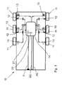
- a trailer vehicle 10 in the manner of a semi-trailer has a pneumatic brake system with an anti-lock function.
- Wheel speed sensors 12 are provided on four of six wheels 11 (two of three axles).
- the function of brake cylinders 13 can be regulated by a control device 14 .
- An electrical line P, a pneumatic pressure line AS and a pneumatic control line AC are connected to the control device 14 .
- a longitudinal acceleration a L and a transverse acceleration a Q are continuously detected by sensors 21 , 22 arranged in control unit 14 in particular.
- the lateral acceleration a Q can be determined from the different speeds of the wheels 11 on the inside and outside of the curve.
- the longitudinal acceleration a L can alternatively or additionally be determined from the change in the wheel speeds.
- an automatic braking process is triggered. This consists of test braking with gradually increasing brake pressure.
- the brake pressure is fed into the brake cylinders in pulses. A duration of about five to ten milliseconds is preferably set for each pulse. Other values can result from the vehicle body and the reaction times of the components involved in the braking process result.
- the following sequences can result:
- Control unit 14 determines a lateral acceleration a Q of more than 3 m/s 2 . This means that the lateral acceleration a QKRIT , which is critical for overturning, has been exceeded.
- the automatic braking process is triggered and the braking pressure on the inside of the curve (contact surface 15 and arrow 18 in figure 2 ) is increased in defined steps, in particular in steps of approximately 0.1 bar.
- the increase in brake pressure can be controlled via the activation times of inlet magnets on control valves.
- the longitudinal acceleration a L is monitored. In this case, a negative longitudinal acceleration a L is determined, the amount of which is greater than the specified limit longitudinal deceleration a LKIPP .
- the measured or calculated lateral acceleration a Q is above the critical lateral acceleration a QKRIT .
- Brake pressure is pulsed up preferably in 0.1 bar increments on the inside of the curve.
- a significantly lower negative longitudinal acceleration a L is now measured or calculated during the automatic braking process.
- the magnitude of the longitudinal acceleration a L is therefore smaller than the limit value a LKIPP of 0.24 m/s 2 .
- This Fall can occur, for example, if the vehicle has a higher center of gravity than in procedure 1.
- the grip of the wheels on the inside of the curve on the road surface is only minimal. The wheels on the inside of the curve do not have enough vertical force and lock, or an anti-lock braking system intervenes for the wheels on the inside of the curve.
- deceleration braking for the trailer vehicle 10 is initiated, at least for the wheels on the outside of the curve, in particular for all wheels.
- the deceleration braking reduces the lateral acceleration a Q to below the critical lateral acceleration a QKRIT .
- the braking process is then aborted because the vehicle is stable again.
- the method can start again, depending on the transverse acceleration a Q determined.
- the measured/calculated lateral acceleration a Q of the vehicle is below the critical lateral acceleration a QKRIT of 3 m/s 2 . This can occur when cornering with a larger radius or when the vehicle's center of gravity is very low. There is no automatic braking process.
Description
- Die Erfindung betrifft ein Verfahren zur automatischen Ansteuerung von Bremsen in Anhängefahrzeugen mit Antiblockierregelung, insbesondere zum Schutz gegen Umkippen, wobei Raddrehzahlen an Rädern mit Antiblockierregelung kontinuierlich überwacht und ausgewertet werden.
- Nutzfahrzeuge sind typischerweise mit einer pneumatischen Bremsanlage und einem elektronischen Bremssystem ausgestattet. Das heißt, vom Fahrer wird ein Bremssignal elektronisch an ein Steuergerät übermittelt. Letzteres regelt Ventile, mit denen Bremsdruck in Fahrzeugbremsen eingesteuert wird. Dem Steuergerät sind allerlei Sensoren und Zusatzfunktionen zugeordnet. Unter anderem kann eine Stabilitätskontrolle vorgesehen sein, nämlich eine Kontrolle gegen Umkippen aufgrund zu schneller Kurvenfahrt. Die Kombination aus pneumatischer Bremsanlage und elektronischem Bremssystem ist auch für Anhängefahrzeuge bekannt.
- Die Schriften
US 2014/0214299 A1 undGB 2499438 A - In elektronischen Bremssystemen wird zur Verifizierung der Umkippgefahr ein geringer Testbremsdruck auf der kurveninneren Fahrzeugseite eingesteuert. Wenn dieser geringe Testbremsdruck ausreicht, um Räder auf der kurveninneren Fahrzeugseite zu blockieren, wird davon ausgegangen, dass die kurveninnere Fahrzeugseite stark entlastet ist und eine Umkippgefahr besteht. Das Fahrzeug wird dann automatisch voll eingebremst, um die Geschwindigkeit zu reduzieren und so das Umkippen zu verhindern. Der Testbremsdruck wird dabei in Abhängigkeit von einer Beladung berechnet, so dass die kurveninneren Räder bei ca. 90 % Entlastung blockieren, ausgehend von einem relativ hohem Reibwert zwischen Reifen und Straße. Erforderlich sind hierzu die Erfassung der Achslasten durch Sensoren und eine relativ genaue Dosierung des Testbremsdrucks. Beides ist typischerweise für einfache Bremsanlagen ohne elektronisches Bremssystem nicht vorgesehen.
- Vorläufer des elektronischen Bremssystems war die sogenannte Antiblockierregelung ohne eine elektronische Übermittlung des Bremssignals vom Fahrer zum Steuergerät. Das Steuergerät hatte nur die Aufgabe Signale der Raddrehzahlsensoren zu überwachen und den wirksamen Bremsdruck für blockierende Räder zu vermindern. Anhängefahrzeuge mit Antiblockierregelung und ohne elektronisches Bremssystem sind weiterhin weit verbreitet.
- Aufgabe der vorliegenden Erfindung ist die Schaffung eines Verfahrens, mit dem Anhängefahrzeuge mit Antiblockierregelung, insbesondere auch ohne elektronisches Bremssystem, gegen das Umkippen in zu schnell gefahrenen Kurven geschützt werden können.
- Die Merkmale des erfindungsgemäßen Verfahrens ergeben sich aus Anspruch 1. Insbesondere sind folgende Schritte vorgesehen:
- a) Überwachung einer Querbeschleunigung aQ und einer Längsbeschleunigung aL des Fahrzeugs,
- b) bei Überschreiten einer vordefinierten, kritischen Querbeschleunigung aQkrit in einer Kurve erfolgt ein automatischer Bremsvorgang mit folgendem Ablauf:
- b1) - erhöhen eines Bremsdrucks auf einer kurveninneren Fahrzeugseite in kleinen Schritten von insbesondere 0,1 - 0,2 bar,
- b2) - in jedem Schritt prüfen, ob eine Grenz-Längsverzögerung aLkipp erreicht wird,
- b3) - in jedem Schritt prüfen, ob kurveninnere Räder blockieren oder die Antiblockierregelung für kurveninnere Räder eingreift,
- b31) - wenn kurveninnere Räder blockieren oder die Antiblockierregelung für kurveninnere Räder eingreift, bevor aLkipp erreicht wird, dann startet eine Verzögerungsbremsung zumindest auf einer kurvenäußeren Fahrzeugseite,
- b32) - wenn jedoch aLkipp erreicht wird, ohne dass kurveninnere Räder blockieren oder für kurveninnere Räder die Antiblockierregelung eingreift, dann wird der Bremsvorgang abgebrochen.
- Die Querbeschleunigung wird vorzugsweise ständig überwacht durch Ermittlung und Vergleich derselben mit der kritischen Querbeschleunigung in sehr kurzen zeitlichen Abständen. Die Längsbeschleunigung wird vorzugsweise nur ermittelt, wenn die kritische Querbeschleunigung überschritten ist, kann aber auch unabhängig davon ermittelt werden.
- Zur Ermittlung der Querbeschleunigung kann für die Antiblockierregelung ein Steuergerät mit Querbeschleunigungssensor vorgesehen sein. Die Längsbeschleunigung kann aus den Signalen der Raddrehzahlsensoren in bekannter Weise ermittelt werden. Alternativ kann zur Erfassung der Längsbeschleunigung ein Längsbeschleunigungssensor vorgesehen sein. In diesem Fall werden vorzugsweise ein Gefälle oder eine Steigung einer Fahrbahn vor Beginn des Bremsvorgangs erfasst und beim Bremsvorgang herausgerechnet.
- Sobald eine Querbeschleunigung vorliegt, wird von einer Kurvenfahrt ausgegangen. Die Querbeschleunigung weist stets nach außen, also gegen eine kurveninnere Richtung.
- Die kritische Querbeschleunigung aQKRIT wird aus dem Fahrzeugaufbau berechnet und/oder aus Erfahrungswerten festgelegt. Analog ist ein Grenzwert aLKIPP für eine Längsverzögerung aus Erfahrungswerten festgelegt oder aus dem Fahrzeugaufbau ermittelt. Ziel ist eine Grenz-Längsverzögerung aLKIPP derart, dass auf Umkippgefahr erkannt wird, wenn eine Achslast auf der kurveninneren Seite weniger als 10% der maximalen Achslast an dieser Stelle beträgt. Ausgehend von einem Lastzug mit Zugfahrzeug und Auflieger mit beispielsweise 4 und 6 Rädern, sollen die 3 kurveninneren Räder des Aufliegers den Lastzug um etwa 2,4 % abbremsen. Dabei handelt es sich um den prozentualen Wert der Bremskraft bezogen auf die Radlast. Das heißt, aLkipp soll etwa 2,4 % betragen. Für einen Lastzug mit mehr Rädern am Zugfahrzeug und weniger Rädern am Auflieger (6+4 statt 4+6) ergibt sich mit 1,6 % ein niedrigerer Wert für aLkipp. Vorzugsweise soll aLkipp zwischen 1,5 % und 3 % liegen.
- Ein besonderer Vorteil des erfindungsgemäßen Verfahrens liegt darin, dass eine zusätzliche Sensierung der Beladung bzw. der Achslasten nicht notwendig ist und so das Verfahren auch für konventionelle Fahrzeuge mit Antiblockierregelung und ohne elektronisches Bremssystem angewendet werden kann. Außerdem ist das Verfahren anwendbar für Fahrzeuge mit elektronischem Bremssystem aber ohne Beladungssensoren. Schließlich kann das Verfahren auch in Fahrzeugen mit Beladungssensoren zum Einsatz kommen, wenn die Signale der Beladungssensoren ausfallen oder nicht genutzt werden sollen.
- Nach einem weiteren Gedanken der Erfindung ist vorgesehen, dass eine gemäß Schritt b.3.1. begonnene Verzögerungsbremsung abgebrochen wird, sobald die Querbeschleunigung aQ kleiner ist als eine kritische Querbeschleunigung aQKRIT. Die Kippgefahr ist dann beseitigt. Die Verzögerungsbremsung muss nicht weiter durchgeführt werden. Anschließend beginnt der gesamte Zyklus von vorn mit Überwachung der Querbeschleunigung aQ und der Längsbeschleunigung aL.
- Nach einem weiteren Gedanken der Erfindung ist vorgesehen, dass nach dem Abbrechen des Bremsvorgangs gemäß Schritt b.3.2. der automatische Bremsvorgang gemäß b erst dann erneut eingeleitet wird,
- wenn die Querbeschleunigung aQ weiter angestiegen ist und um einen definierten Betrag über der kritischen Querbeschleunigung aQKRIT liegt,
- oder wenn das Fahrzeug eine definierte Distanz seit dem letzten Bremsvorgang gemäß b zurückgelegt hat und die Querbeschleunigung aQ noch immer größer ist als die kritische Querbeschleunigung aQKRIT.
- Der Bremsdruck wird auf der kurveninneren Fahrzeugseite stufenweise erhöht. Während jeder Stufe wird ein Bremsdruck über eine definierte Zeitspanne eingesteuert. Diese Zeitspanne wird als Einsteuerzeit des Bremsdruckes zum Aufpulsen bezeichnet und liegt vorzugsweise bei etwa fünf bis zehn Millisekunden. Die Zeitspanne wird aus Parametern des Fahrzeugaufbaus ermittelt oder aufgrund von Erfahrungswerten festgelegt.
- Weitere Merkmale der Erfindung ergeben sich aus der Beschreibung im Übrigen und aus den Ansprüchen. Vorteilhafte Ausführungsformen der Erfindung werden nachfolgend anhand von Zeichnungen näher erläutert. Es zeigen:
-
Figur 1 die schematische Darstellung einer pneumatischen Bremsanlage eines Anhängefahrzeugs (Auflieger) mit drei Achsen, -
Figur 2 das Anhängefahrzeug in Rückansicht mit Darstellung der Kräfte in einer Linkskurve, -
Figur 3 eine schematische Draufsicht auf das Anhängefahrzeug mit Zugmaschine bei Fahrt durch eine Linkskurve. - Ein Anhängefahrzeug 10 nach Art eines Aufliegers weist eine pneumatische Bremsanlage mit Antiblockierfunktion auf. An vier von sechs Rädern 11 (zwei von drei Achsen) sind Raddrehzahlsensoren 12 vorgesehen. Die Funktion von Bremszylindern 13 ist durch ein Steuergerät 14 regelbar. An das Steuergerät 14 angeschlossen sind eine elektrische Leitung P, eine pneumatische Druckleitung AS und eine pneumatische Steuerleitung AC.
- Bei schneller Kurvenfahrt und/oder relativ hohem Schwerpunkt S des Anhängefahrzeugs 10 besteht die Gefahr des Umkippens. Ausgehend von einer Höhe h bzw. einer Lage des Schwerpunkts S, einer Zentrifugalkraft FZ und einer ladungsabhängigen, vertikal gerichteten Gewichtskraft FV ergibt sich eine resultierende Kraft FR, siehe
Figur 2 . Entsprechende Kräfte stellen sich im Bereich von Kontaktflächen 15, 16 zwischen Rädern 11 und Fahrbahn 17 ein, siehe Pfeile 18 (Aufstandskraft links), 19 (Aufstandskraft rechts) und 20 (Seitenführungskraft). Erkennbar ist, dass bei größer werdender Zentrifugalkraft FZ die resultierende Kraft FR immer weiter von der Vertikalkraft FV abweicht und entsprechend die Aufstandskraft links (Pfeil 18) kleiner wird. Im Extremfall ändert die Aufstandskraft links ihr Vorzeichen und das Anhängefahrzeug 10 kippt um. - Zur Vermeidung des Umkippens bei Kurvenfahrt werden fortlaufend eine Längsbeschleunigung aL und eine Querbeschleunigung aQ durch insbesondere im Steuergerät 14 angeordnete Sensoren 21, 22 detektiert. Alternativ oder zusätzlich kann die Querbeschleunigung aQ aus den unterschiedlichen Drehzahlen der kurveninneren und kurvenäußeren Räder 11 bestimmt werden. Analog kann die Längsbeschleunigung aL alternativ oder zusätzlich aus der Änderung der Raddrehzahlen ermittelt werden.
- Ein Fahrzeuggespann aus Zugfahrzeug 23 und Anhängefahrzeug 10 fährt beispielsweise mit einer Geschwindigkeit von v=60 km/h in eine Kurve. Die Fahrzeugquerbeschleunigung aQ wird laufend überwacht, ebenso die Fahrzeuglängsbeschleunigung aL. Aus dem Fahrzeugaufbau und/oder aus Erfahrungswerten festgelegt ist eine kippkritische Querbeschleunigung aQKRIT. Analog ist ein Grenzwert aLKIPP für eine Längsverzögerung aus Erfahrungswerten festgelegt oder aus dem Fahrzeugaufbau ermittelt. Hier soll gelten:
- aQKRIT = 3 m/s2
- aLKIPP = 0,24 m/s2 (oder 0,16 m/s2 für Auflieger mit zwei Achsen, wie in Nordamerika).
- Bei Überschreitung der kippkritischen Querbeschleunigung aQKRIT wird ein automatischer Bremsvorgang ausgelöst. Dieser besteht aus Testbremsungen mit stufenweise größer werdendem Bremsdruck. Der Bremsdruck wird in Pulsen in die Bremszylinder eingesteuert. Für jeden Puls wird vorzugsweise eine Zeitdauer von etwa fünf bis zehn Millisekunden angesetzt. Andere Werte können sich aus dem Fahrzeugaufbau und den Reaktionszeiten der am Bremsvorgang beteiligten Bauteile ergeben. Je nach Lenkwinkel und Schwerpunkt bei vorgegebener Geschwindigkeit v von 60 km/h können sich folgende Abläufe ergeben:
- Das Steuergerät 14 stellt eine Querbeschleunigung aQ von mehr als 3 m/s2 fest. Damit ist die kippkritische Querbeschleunigung aQKRIT überschritten. Der automatische Bremsvorgang wird ausgelöst und der Bremsdruck auf der kurveninneren Seite (Kontaktfläche 15 und Pfeil 18 in
Figur 2 ) wird in definierten Schritten erhöht, insbesondere in etwa 0,1 bar-Schritten. In üblichen Antiblockierregelungen kann die Erhöhung des Bremsdruckes gesteuert werden über Ansteuerzeiten von Einlassmagneten an Steuerventilen. Zugleich wird die Längsbeschleunigung aL überwacht. In diesem Fall wird eine negative Längsbeschleunigung aL festgestellt, deren Betrag größer ist als die vorgegebene Grenz-Längsverzögerung aLKIPP. Das heißt, durch den automatischen Bremsvorgang der kurveninneren Räder verzögert das Anhängefahrzeug stärker als die Grenz-Längsverzögerung aLKIPP vorgibt. Die kurveninneren Räder blockieren nicht. Somit haben die abgebremsten Räder auf der kurveninneren Seite noch genügend Aufstandskraft. Es besteht keine Gefahr des Umkippens. Der automatische Bremsvorgang wird abgebrochen. Die zuletzt gemessene oder errechnete Querbeschleunigung aQ wird aber bis auf Weiteres gespeichert. - Sollte sich die Querbeschleunigung aQ weiter erhöhen, etwa um eine definierte Differenz oder um 5% bis 10%, findet wieder ein automatischer Bremsvorgang statt.
- Wie in Ablauf 1 liegt die gemessene oder berechnete Querbeschleunigung aQ über der kritischen Querbeschleunigung aQKRIT. Bremsdruck wird in vorzugsweise 0,1 bar-Schritten auf der kurveninneren Seite aufgepulst. Im Gegensatz zu Ablauf 1 wird nun eine deutlich geringere negative Längsbeschleunigung aL während des automatischen Bremsvorgangs gemessen oder berechnet. Der Betrag der Längsbeschleunigung aL ist somit kleiner als der Grenzwert aLKIPP von 0,24 m/s2. Dieser Fall kann zum Beispiel auftreten, wenn das Fahrzeug einen höher liegenden Schwerpunkt als in Ablauf 1 aufweist. Die Haftung der kurveninneren Räder auf dem Straßenbelag ist nur noch gering. Die kurveninneren Räder haben nicht genügend Aufstandskraft und blockieren oder für die kurveninneren Räder greift eine Antiblockierregelung ein. Als Folge wird eine Verzögerungsbremsung für das Anhängefahrzeug 10 eingeleitet, zumindest für die kurvenäußeren Räder, insbesondere für alle Räder. Durch die Verzögerungsbremsung wird die Querbeschleunigung aQ bis unter die kritische Querbeschleunigung aQKRIT verringert. Anschließend wird der Bremsvorgang abgebrochen, da das Fahrzeug wieder stabil ist. Das Verfahren kann von neuem beginnen, je nach ermittelter Querbeschleunigung aQ.
- Die gemessene/berechnete Querbeschleunigung aQ des Fahrzeugs liegt unter der kritischen Querbeschleunigung aQKRIT von 3 m/s2. Dieser Fall kann auftreten in Kurven mit größerem Radius oder bei sehr niedrigem Schwerpunkt des Fahrzeugs. Es findet kein automatischer Bremsvorgang statt.
Claims (3)
- Verfahren zur automatischen Ansteuerung von Bremsen in Anhängefahrzeugen (10) mit Antiblockierregelung, insbesondere zum Schutz gegen Umkippen, wobei Raddrehzahlen an Rädern (11) mit Antiblockierregelung kontinuierlich überwacht und ausgewertet werden, gekennzeichnet durch folgende Merkmale:a) Ermittlung einer Querbeschleunigung ao und einer Längsbeschleunigung aL des Fahrzeugs (10),b) bei Überschreiten einer vordefinierten, kritischen Querbeschleunigung aQkrit erfolgt ein automatischer Bremsvorgang mit folgendem Ablauf:b1) - erhöhen eines Bremsdrucks auf einer kurveninneren Fahrzeugseite in kleinen Schritten von insbesondere 0,1 - 0,2 bar,b2) - in jedem Schritt prüfen, ob eine Grenz-Längsverzögerung aLkipp erreicht wird,b3) - in jedem Schritt prüfen, ob kurveninnere Räder (11) blockieren oder die Antiblockierregelung für kurveninnere Räder (11) eingreift,b31) - wenn kurveninnere Räder (11) blockieren oder die Antiblockierregelung für kurveninnere Räder (11) eingreift, bevor aLkipp erreicht wird, dann startet eine Verzögerungsbremsung zumindest auf einer kurvenäußeren Fahrzeugseite,b32) - wenn jedoch aLkipp erreicht wird, ohne dass kurveninnere Räder (11) blockieren oder für kurveninnere Räder (11) die Antiblockierregelung eingreift, dann wird der Bremsvorgang abgebrochen.
- Verfahren nach Anspruch 1, dadurch gekennzeichnet, dass eine gemäß Schritt b.3.1. begonnene Verzögerungsbremsung abgebrochen wird, sobald die Querbeschleunigung ao kleiner ist als eine kritische Querbeschleunigung aQKRIT.
- Verfahren nach Anspruch 1 oder 2, dadurch gekennzeichnet, dass nach dem Abbrechen des Bremsvorgangs gemäß Schritt b.3.2. der automatische Bremsvorgang gemäß b erst dann erneut eingeleitet wird,- wenn die Querbeschleunigung ao weiter angestiegen ist und um einen definierten Betrag über der kritischen Querbeschleunigung aQKRIT liegt,- oder wenn das Fahrzeug (10) eine definierte Distanz seit dem letzten Bremsvorgang gemäß b zurückgelegt hat und die Querbeschleunigung ao noch größer ist als die kritische Querbeschleunigung aQKRIT.
Applications Claiming Priority (2)
| Application Number | Priority Date | Filing Date | Title |
|---|---|---|---|
| DE102015013761.1A DE102015013761A1 (de) | 2015-10-23 | 2015-10-23 | Verfahren zur Ansteuerung von Bremsen |
| PCT/EP2016/001411 WO2017067622A1 (de) | 2015-10-23 | 2016-08-19 | Verfahren zur ansteuerung von bremsen |
Publications (2)
| Publication Number | Publication Date |
|---|---|
| EP3365205A1 EP3365205A1 (de) | 2018-08-29 |
| EP3365205B1 true EP3365205B1 (de) | 2022-06-15 |
Family
ID=56740186
Family Applications (1)
| Application Number | Title | Priority Date | Filing Date |
|---|---|---|---|
| EP16753829.7A Active EP3365205B1 (de) | 2015-10-23 | 2016-08-19 | Verfahren zur ansteuerung von bremsen |
Country Status (6)
| Country | Link |
|---|---|
| US (1) | US10661769B2 (de) |
| EP (1) | EP3365205B1 (de) |
| CN (1) | CN107848510B (de) |
| BR (1) | BR112018008277B1 (de) |
| DE (1) | DE102015013761A1 (de) |
| WO (1) | WO2017067622A1 (de) |
Families Citing this family (6)
| Publication number | Priority date | Publication date | Assignee | Title |
|---|---|---|---|---|
| DE102016011282A1 (de) * | 2016-09-20 | 2018-03-22 | Wabco Gmbh | Verfahren zum Durchführen eines Ausweichmanövers mit einem Nutzfahrzeug-Gespann, sowie Notausweichsystem |
| DE102017000547A1 (de) * | 2017-01-21 | 2018-07-26 | Wabco Gmbh | Verfahren zur Verzögerung eines Anhängefahrzeugs, Radmodul zur Durchführung des Verfahrens sowie Fahrzeugkombination mit einem solchen Radmodul |
| DE102017010867A1 (de) * | 2017-11-24 | 2019-05-29 | Knorr-Bremse Systeme für Nutzfahrzeuge GmbH | Verfahren und Vorrichtung zum Steuern einer Bremsanlage eines Anhängers während einer Kurvenfahrt |
| CN111267853B (zh) * | 2018-12-03 | 2021-06-18 | 广州汽车集团股份有限公司 | 一种自适应车辆弯道辅助控制方法、装置、计算机设备和存储介质 |
| DE102021114305A1 (de) | 2021-06-02 | 2022-12-08 | Zf Cv Systems Europe Bv | Verfahren und elektronisches Steuergerät zur Steuerung einer Bremsanlage eines Kraftfahrzeugs |
| GB2620962A (en) * | 2022-07-28 | 2024-01-31 | Continental Automotive Gmbh | Vehicle load regulating system and method thereof |
Family Cites Families (13)
| Publication number | Priority date | Publication date | Assignee | Title |
|---|---|---|---|---|
| DE19602879C1 (de) * | 1996-01-29 | 1997-08-07 | Knorr Bremse Systeme | Verfahren zum Erfassen der Gefahr des Umkippens eines Fahrzeuges |
| JP4117425B2 (ja) | 1998-07-29 | 2008-07-16 | 三菱ふそうトラック・バス株式会社 | 連結車両の制動制御装置 |
| DE10017045A1 (de) | 2000-04-05 | 2001-10-11 | Wabco Gmbh & Co Ohg | Verfahren zur Vermeidung des Umkippens eines Fahrzeuges um seine Längsachse |
| DE10026688C1 (de) * | 2000-05-30 | 2001-09-13 | Knorr Bremse Systeme | Verfahren und Vorrichtung zur Bestimmung des Ansprechdrucks von Fahrzeugbremsen |
| US6741922B2 (en) | 2002-05-30 | 2004-05-25 | Bendix Commercial Vehicle Systems Llc | Antilock braking system based roll over prevention |
| DE10338879A1 (de) | 2003-08-23 | 2005-03-17 | Wabco Gmbh & Co.Ohg | Verfahren zur Abschätzung einer Querbeschleunigung eines Fahrzeugs |
| US7311364B2 (en) * | 2003-10-09 | 2007-12-25 | Hayes Brake Controller Company, Llc | Electric trailer brake controller |
| JP4269994B2 (ja) * | 2004-03-25 | 2009-05-27 | 三菱ふそうトラック・バス株式会社 | 車両のステア特性制御装置 |
| JP4730065B2 (ja) * | 2005-11-14 | 2011-07-20 | 株式会社アドヴィックス | 車両の運動制御装置 |
| US8359146B2 (en) * | 2005-12-15 | 2013-01-22 | Bendix Commercial Vehicle Systems Llc | Single channel roll stability system |
| GB2454224B (en) * | 2007-11-01 | 2013-01-23 | Haldex Brake Products Ltd | Vehicle stability control apparatus |
| DE102011111862A1 (de) * | 2011-08-31 | 2013-02-28 | Wabco Gmbh | Verfahren zur Warnung des Fahrers eines Fahrzeuges vor einem drohenden Umkippen und Steuerungseinrichtung dafür |
| GB2499438B (en) | 2012-02-17 | 2018-10-17 | Haldex Brake Prod Ab | Method of vehicle stability control |
-
2015
- 2015-10-23 DE DE102015013761.1A patent/DE102015013761A1/de active Pending
-
2016
- 2016-08-19 WO PCT/EP2016/001411 patent/WO2017067622A1/de active Application Filing
- 2016-08-19 BR BR112018008277-5A patent/BR112018008277B1/pt active IP Right Grant
- 2016-08-19 US US15/770,382 patent/US10661769B2/en active Active
- 2016-08-19 EP EP16753829.7A patent/EP3365205B1/de active Active
- 2016-08-19 CN CN201680046201.2A patent/CN107848510B/zh active Active
Also Published As
| Publication number | Publication date |
|---|---|
| BR112018008277B1 (pt) | 2022-12-06 |
| DE102015013761A1 (de) | 2017-04-27 |
| US20180312148A1 (en) | 2018-11-01 |
| BR112018008277A2 (pt) | 2018-10-23 |
| US10661769B2 (en) | 2020-05-26 |
| EP3365205A1 (de) | 2018-08-29 |
| CN107848510A (zh) | 2018-03-27 |
| CN107848510B (zh) | 2021-10-08 |
| WO2017067622A8 (de) | 2018-01-25 |
| WO2017067622A1 (de) | 2017-04-27 |
Similar Documents
| Publication | Publication Date | Title |
|---|---|---|
| EP3365205B1 (de) | Verfahren zur ansteuerung von bremsen | |
| EP2404800B1 (de) | Verfahren und Vorrichtung zur Durchführung einer Bremsenprüfung an Anhänger- und / oder Aufliegerfahrzeugen | |
| EP1427619B1 (de) | Verfahren zur Fahrzustandsstabilisierung eines Nutzfahrzeugverbandes | |
| EP1601561B1 (de) | Verfahren und system zur regelung der fahrstabilität eines fahrzeugs und verwendung des systems | |
| EP2862772B1 (de) | Verfahren zur Überprüfung eines Beladungszustandes eines Aufliegers oder Anhängers eines Nutzfahrzeuges | |
| EP2058190B1 (de) | Fahrerassistenzsystem für Kraftfahrzeuggespanne | |
| DE10149190A1 (de) | Vorrichtung und Verfahren zur Wankregelung für ein Fahrzeug | |
| WO2009127291A1 (de) | Verfahren und vorrichtung zur stabilitätsregelung eines fahrzeuges, insbesondere nutzfahrzeuges | |
| DE102012000784A1 (de) | Stabilisierung eines Fahrzeuggespanns | |
| EP1480855B1 (de) | Verfahren und vorrichtung zur erkennung abgehobener fahrzeugräder | |
| DE102015009160A1 (de) | Verfahren und Vorrichtung zum elektronischen Regeln einer Fahrzeugverzögerung eines bremsschlupfgeregelten Fahrzeuges | |
| EP2750942A2 (de) | Verfahren zur warnung des fahrers eines fahrzeuges vor einem drohenden umkippen und steuerungseinrichtung dafür | |
| DE102015221833A1 (de) | Fahrzeuglastinformationssystem zur Bestimmung einer Starßenneigung und einer Last bei am Fahrzeug angefügtem Anhänger | |
| DE102013207127A1 (de) | Verfahren zum Anpassen eines Bremsvorgangs | |
| EP2590845B1 (de) | Verfahren zur bestimmung einer fahrzeugreferenzgeschwindigkeit und bremsanlage | |
| DE19963402A1 (de) | Verfahren und Vorrichtung zur Ermittlung des Gewichts/der Masse eines Fahrzeugs | |
| DE19844542A1 (de) | Vorrichtung und Verfahren zum Begrenzen einer Rückrollgeschwindigkeit eines Kraftfahrzeuges | |
| EP1726471A1 (de) | Geschwindigkeitsregler für Kraftfahrzeuge | |
| DE10232792A1 (de) | Bremsverfahren für ein Fahrzeug | |
| DE102010027985A1 (de) | Verfahren zum Bremsen eines Kraftfahrzeugs in kritischen Fahrsituationen | |
| DE19858583B4 (de) | Verfahren und Vorrichtung zur Steuerung einer Bremsanlage eines Fahrzeugs | |
| DE10225447B4 (de) | Verfahren und Vorrichtung zur Regelung wenigstens einer Fahrdynamikgröße | |
| EP3606795B1 (de) | Bremsregelungssystem für kraftfahrzeuge | |
| DE102012101274A1 (de) | Verfahren zur Steuerung eines Kraftfahrzeugs während und unmittelbar nach einer Flugphase | |
| DE102004035576A1 (de) | Stabilisierungsvorrichtung und Verfahren zur Fahrstabilisierung eines Fahrzeugs anhand eines Wankwerts |
Legal Events
| Date | Code | Title | Description |
|---|---|---|---|
| STAA | Information on the status of an ep patent application or granted ep patent |
Free format text: STATUS: THE INTERNATIONAL PUBLICATION HAS BEEN MADE |
|
| PUAI | Public reference made under article 153(3) epc to a published international application that has entered the european phase |
Free format text: ORIGINAL CODE: 0009012 |
|
| STAA | Information on the status of an ep patent application or granted ep patent |
Free format text: STATUS: REQUEST FOR EXAMINATION WAS MADE |
|
| 17P | Request for examination filed |
Effective date: 20180523 |
|
| AK | Designated contracting states |
Kind code of ref document: A1 Designated state(s): AL AT BE BG CH CY CZ DE DK EE ES FI FR GB GR HR HU IE IS IT LI LT LU LV MC MK MT NL NO PL PT RO RS SE SI SK SM TR |
|
| AX | Request for extension of the european patent |
Extension state: BA ME |
|
| DAV | Request for validation of the european patent (deleted) | ||
| DAX | Request for extension of the european patent (deleted) | ||
| STAA | Information on the status of an ep patent application or granted ep patent |
Free format text: STATUS: EXAMINATION IS IN PROGRESS |
|
| STAA | Information on the status of an ep patent application or granted ep patent |
Free format text: STATUS: EXAMINATION IS IN PROGRESS |
|
| 17Q | First examination report despatched |
Effective date: 20201109 |
|
| RAP3 | Party data changed (applicant data changed or rights of an application transferred) |
Owner name: ZF CV SYSTEMS HANNOVER GMBH |
|
| STAA | Information on the status of an ep patent application or granted ep patent |
Free format text: STATUS: EXAMINATION IS IN PROGRESS |
|
| RAP1 | Party data changed (applicant data changed or rights of an application transferred) |
Owner name: ZF CV SYSTEMS EUROPE BV |
|
| GRAP | Despatch of communication of intention to grant a patent |
Free format text: ORIGINAL CODE: EPIDOSNIGR1 |
|
| STAA | Information on the status of an ep patent application or granted ep patent |
Free format text: STATUS: GRANT OF PATENT IS INTENDED |
|
| INTG | Intention to grant announced |
Effective date: 20220316 |
|
| GRAS | Grant fee paid |
Free format text: ORIGINAL CODE: EPIDOSNIGR3 |
|
| GRAA | (expected) grant |
Free format text: ORIGINAL CODE: 0009210 |
|
| STAA | Information on the status of an ep patent application or granted ep patent |
Free format text: STATUS: THE PATENT HAS BEEN GRANTED |
|
| AK | Designated contracting states |
Kind code of ref document: B1 Designated state(s): AL AT BE BG CH CY CZ DE DK EE ES FI FR GB GR HR HU IE IS IT LI LT LU LV MC MK MT NL NO PL PT RO RS SE SI SK SM TR |
|
| REG | Reference to a national code |
Ref country code: CH Ref legal event code: EP Ref country code: GB Ref legal event code: FG4D Free format text: NOT ENGLISH |
|
| REG | Reference to a national code |
Ref country code: IE Ref legal event code: FG4D Free format text: LANGUAGE OF EP DOCUMENT: GERMAN |
|
| REG | Reference to a national code |
Ref country code: DE Ref legal event code: R096 Ref document number: 502016014971 Country of ref document: DE |
|
| REG | Reference to a national code |
Ref country code: AT Ref legal event code: REF Ref document number: 1498210 Country of ref document: AT Kind code of ref document: T Effective date: 20220715 |
|
| REG | Reference to a national code |
Ref country code: LT Ref legal event code: MG9D |
|
| REG | Reference to a national code |
Ref country code: NL Ref legal event code: MP Effective date: 20220615 |
|
| PG25 | Lapsed in a contracting state [announced via postgrant information from national office to epo] |
Ref country code: SE Free format text: LAPSE BECAUSE OF FAILURE TO SUBMIT A TRANSLATION OF THE DESCRIPTION OR TO PAY THE FEE WITHIN THE PRESCRIBED TIME-LIMIT Effective date: 20220615 Ref country code: NO Free format text: LAPSE BECAUSE OF FAILURE TO SUBMIT A TRANSLATION OF THE DESCRIPTION OR TO PAY THE FEE WITHIN THE PRESCRIBED TIME-LIMIT Effective date: 20220915 Ref country code: LT Free format text: LAPSE BECAUSE OF FAILURE TO SUBMIT A TRANSLATION OF THE DESCRIPTION OR TO PAY THE FEE WITHIN THE PRESCRIBED TIME-LIMIT Effective date: 20220615 Ref country code: HR Free format text: LAPSE BECAUSE OF FAILURE TO SUBMIT A TRANSLATION OF THE DESCRIPTION OR TO PAY THE FEE WITHIN THE PRESCRIBED TIME-LIMIT Effective date: 20220615 Ref country code: GR Free format text: LAPSE BECAUSE OF FAILURE TO SUBMIT A TRANSLATION OF THE DESCRIPTION OR TO PAY THE FEE WITHIN THE PRESCRIBED TIME-LIMIT Effective date: 20220916 Ref country code: FI Free format text: LAPSE BECAUSE OF FAILURE TO SUBMIT A TRANSLATION OF THE DESCRIPTION OR TO PAY THE FEE WITHIN THE PRESCRIBED TIME-LIMIT Effective date: 20220615 Ref country code: BG Free format text: LAPSE BECAUSE OF FAILURE TO SUBMIT A TRANSLATION OF THE DESCRIPTION OR TO PAY THE FEE WITHIN THE PRESCRIBED TIME-LIMIT Effective date: 20220915 |
|
| PG25 | Lapsed in a contracting state [announced via postgrant information from national office to epo] |
Ref country code: RS Free format text: LAPSE BECAUSE OF FAILURE TO SUBMIT A TRANSLATION OF THE DESCRIPTION OR TO PAY THE FEE WITHIN THE PRESCRIBED TIME-LIMIT Effective date: 20220615 Ref country code: LV Free format text: LAPSE BECAUSE OF FAILURE TO SUBMIT A TRANSLATION OF THE DESCRIPTION OR TO PAY THE FEE WITHIN THE PRESCRIBED TIME-LIMIT Effective date: 20220615 |
|
| PG25 | Lapsed in a contracting state [announced via postgrant information from national office to epo] |
Ref country code: NL Free format text: LAPSE BECAUSE OF FAILURE TO SUBMIT A TRANSLATION OF THE DESCRIPTION OR TO PAY THE FEE WITHIN THE PRESCRIBED TIME-LIMIT Effective date: 20220615 |
|
| PG25 | Lapsed in a contracting state [announced via postgrant information from national office to epo] |
Ref country code: SM Free format text: LAPSE BECAUSE OF FAILURE TO SUBMIT A TRANSLATION OF THE DESCRIPTION OR TO PAY THE FEE WITHIN THE PRESCRIBED TIME-LIMIT Effective date: 20220615 Ref country code: SK Free format text: LAPSE BECAUSE OF FAILURE TO SUBMIT A TRANSLATION OF THE DESCRIPTION OR TO PAY THE FEE WITHIN THE PRESCRIBED TIME-LIMIT Effective date: 20220615 Ref country code: RO Free format text: LAPSE BECAUSE OF FAILURE TO SUBMIT A TRANSLATION OF THE DESCRIPTION OR TO PAY THE FEE WITHIN THE PRESCRIBED TIME-LIMIT Effective date: 20220615 Ref country code: PT Free format text: LAPSE BECAUSE OF FAILURE TO SUBMIT A TRANSLATION OF THE DESCRIPTION OR TO PAY THE FEE WITHIN THE PRESCRIBED TIME-LIMIT Effective date: 20221017 Ref country code: ES Free format text: LAPSE BECAUSE OF FAILURE TO SUBMIT A TRANSLATION OF THE DESCRIPTION OR TO PAY THE FEE WITHIN THE PRESCRIBED TIME-LIMIT Effective date: 20220615 Ref country code: EE Free format text: LAPSE BECAUSE OF FAILURE TO SUBMIT A TRANSLATION OF THE DESCRIPTION OR TO PAY THE FEE WITHIN THE PRESCRIBED TIME-LIMIT Effective date: 20220615 Ref country code: CZ Free format text: LAPSE BECAUSE OF FAILURE TO SUBMIT A TRANSLATION OF THE DESCRIPTION OR TO PAY THE FEE WITHIN THE PRESCRIBED TIME-LIMIT Effective date: 20220615 |
|
| PG25 | Lapsed in a contracting state [announced via postgrant information from national office to epo] |
Ref country code: PL Free format text: LAPSE BECAUSE OF FAILURE TO SUBMIT A TRANSLATION OF THE DESCRIPTION OR TO PAY THE FEE WITHIN THE PRESCRIBED TIME-LIMIT Effective date: 20220615 Ref country code: IS Free format text: LAPSE BECAUSE OF FAILURE TO SUBMIT A TRANSLATION OF THE DESCRIPTION OR TO PAY THE FEE WITHIN THE PRESCRIBED TIME-LIMIT Effective date: 20221015 |
|
| REG | Reference to a national code |
Ref country code: DE Ref legal event code: R097 Ref document number: 502016014971 Country of ref document: DE |
|
| PG25 | Lapsed in a contracting state [announced via postgrant information from national office to epo] |
Ref country code: MC Free format text: LAPSE BECAUSE OF FAILURE TO SUBMIT A TRANSLATION OF THE DESCRIPTION OR TO PAY THE FEE WITHIN THE PRESCRIBED TIME-LIMIT Effective date: 20220615 Ref country code: AL Free format text: LAPSE BECAUSE OF FAILURE TO SUBMIT A TRANSLATION OF THE DESCRIPTION OR TO PAY THE FEE WITHIN THE PRESCRIBED TIME-LIMIT Effective date: 20220615 |
|
| REG | Reference to a national code |
Ref country code: CH Ref legal event code: PL |
|
| PLBE | No opposition filed within time limit |
Free format text: ORIGINAL CODE: 0009261 |
|
| STAA | Information on the status of an ep patent application or granted ep patent |
Free format text: STATUS: NO OPPOSITION FILED WITHIN TIME LIMIT |
|
| PG25 | Lapsed in a contracting state [announced via postgrant information from national office to epo] |
Ref country code: LU Free format text: LAPSE BECAUSE OF NON-PAYMENT OF DUE FEES Effective date: 20220819 Ref country code: LI Free format text: LAPSE BECAUSE OF NON-PAYMENT OF DUE FEES Effective date: 20220831 Ref country code: DK Free format text: LAPSE BECAUSE OF FAILURE TO SUBMIT A TRANSLATION OF THE DESCRIPTION OR TO PAY THE FEE WITHIN THE PRESCRIBED TIME-LIMIT Effective date: 20220615 Ref country code: CH Free format text: LAPSE BECAUSE OF NON-PAYMENT OF DUE FEES Effective date: 20220831 |
|
| REG | Reference to a national code |
Ref country code: BE Ref legal event code: MM Effective date: 20220831 |
|
| 26N | No opposition filed |
Effective date: 20230316 |
|
| PG25 | Lapsed in a contracting state [announced via postgrant information from national office to epo] |
Ref country code: SI Free format text: LAPSE BECAUSE OF FAILURE TO SUBMIT A TRANSLATION OF THE DESCRIPTION OR TO PAY THE FEE WITHIN THE PRESCRIBED TIME-LIMIT Effective date: 20220615 |
|
| P01 | Opt-out of the competence of the unified patent court (upc) registered |
Effective date: 20230528 |
|
| PG25 | Lapsed in a contracting state [announced via postgrant information from national office to epo] |
Ref country code: IE Free format text: LAPSE BECAUSE OF NON-PAYMENT OF DUE FEES Effective date: 20220819 |
|
| PGFP | Annual fee paid to national office [announced via postgrant information from national office to epo] |
Ref country code: FR Payment date: 20230620 Year of fee payment: 8 |
|
| PG25 | Lapsed in a contracting state [announced via postgrant information from national office to epo] |
Ref country code: BE Free format text: LAPSE BECAUSE OF NON-PAYMENT OF DUE FEES Effective date: 20220831 |
|
| REG | Reference to a national code |
Ref country code: AT Ref legal event code: MM01 Ref document number: 1498210 Country of ref document: AT Kind code of ref document: T Effective date: 20220819 |
|
| PG25 | Lapsed in a contracting state [announced via postgrant information from national office to epo] |
Ref country code: AT Free format text: LAPSE BECAUSE OF NON-PAYMENT OF DUE FEES Effective date: 20220819 |
|
| PGFP | Annual fee paid to national office [announced via postgrant information from national office to epo] |
Ref country code: GB Payment date: 20230629 Year of fee payment: 8 |
|
| PGFP | Annual fee paid to national office [announced via postgrant information from national office to epo] |
Ref country code: DE Payment date: 20230627 Year of fee payment: 8 |
|
| PG25 | Lapsed in a contracting state [announced via postgrant information from national office to epo] |
Ref country code: IT Free format text: LAPSE BECAUSE OF FAILURE TO SUBMIT A TRANSLATION OF THE DESCRIPTION OR TO PAY THE FEE WITHIN THE PRESCRIBED TIME-LIMIT Effective date: 20220615 |
|
| PG25 | Lapsed in a contracting state [announced via postgrant information from national office to epo] |
Ref country code: HU Free format text: LAPSE BECAUSE OF FAILURE TO SUBMIT A TRANSLATION OF THE DESCRIPTION OR TO PAY THE FEE WITHIN THE PRESCRIBED TIME-LIMIT; INVALID AB INITIO Effective date: 20160819 |