EP3363549B1 - Ultraschallsonde - Google Patents
Ultraschallsonde Download PDFInfo
- Publication number
- EP3363549B1 EP3363549B1 EP18157636.4A EP18157636A EP3363549B1 EP 3363549 B1 EP3363549 B1 EP 3363549B1 EP 18157636 A EP18157636 A EP 18157636A EP 3363549 B1 EP3363549 B1 EP 3363549B1
- Authority
- EP
- European Patent Office
- Prior art keywords
- layer
- section
- sound
- ultrasonic probe
- piezoelectric layer
- Prior art date
- Legal status (The legal status is an assumption and is not a legal conclusion. Google has not performed a legal analysis and makes no representation as to the accuracy of the status listed.)
- Active
Links
Images


Classifications
-
- G—PHYSICS
- G01—MEASURING; TESTING
- G01N—INVESTIGATING OR ANALYSING MATERIALS BY DETERMINING THEIR CHEMICAL OR PHYSICAL PROPERTIES
- G01N29/00—Investigating or analysing materials by the use of ultrasonic, sonic or infrasonic waves; Visualisation of the interior of objects by transmitting ultrasonic or sonic waves through the object
- G01N29/22—Details, e.g. general constructional or apparatus details
- G01N29/24—Probes
- G01N29/2437—Piezoelectric probes
-
- A—HUMAN NECESSITIES
- A61—MEDICAL OR VETERINARY SCIENCE; HYGIENE
- A61B—DIAGNOSIS; SURGERY; IDENTIFICATION
- A61B8/00—Diagnosis using ultrasonic, sonic or infrasonic waves
- A61B8/44—Constructional features of the ultrasonic, sonic or infrasonic diagnostic device
- A61B8/4483—Constructional features of the ultrasonic, sonic or infrasonic diagnostic device characterised by features of the ultrasound transducer
- A61B8/4494—Constructional features of the ultrasonic, sonic or infrasonic diagnostic device characterised by features of the ultrasound transducer characterised by the arrangement of the transducer elements
-
- A—HUMAN NECESSITIES
- A61—MEDICAL OR VETERINARY SCIENCE; HYGIENE
- A61B—DIAGNOSIS; SURGERY; IDENTIFICATION
- A61B8/00—Diagnosis using ultrasonic, sonic or infrasonic waves
- A61B8/44—Constructional features of the ultrasonic, sonic or infrasonic diagnostic device
- A61B8/4444—Constructional features of the ultrasonic, sonic or infrasonic diagnostic device related to the probe
-
- A—HUMAN NECESSITIES
- A61—MEDICAL OR VETERINARY SCIENCE; HYGIENE
- A61B—DIAGNOSIS; SURGERY; IDENTIFICATION
- A61B8/00—Diagnosis using ultrasonic, sonic or infrasonic waves
- A61B8/44—Constructional features of the ultrasonic, sonic or infrasonic diagnostic device
- A61B8/4477—Constructional features of the ultrasonic, sonic or infrasonic diagnostic device using several separate ultrasound transducers or probes
-
- B—PERFORMING OPERATIONS; TRANSPORTING
- B06—GENERATING OR TRANSMITTING MECHANICAL VIBRATIONS IN GENERAL
- B06B—METHODS OR APPARATUS FOR GENERATING OR TRANSMITTING MECHANICAL VIBRATIONS OF INFRASONIC, SONIC, OR ULTRASONIC FREQUENCY, e.g. FOR PERFORMING MECHANICAL WORK IN GENERAL
- B06B1/00—Methods or apparatus for generating mechanical vibrations of infrasonic, sonic, or ultrasonic frequency
- B06B1/02—Methods or apparatus for generating mechanical vibrations of infrasonic, sonic, or ultrasonic frequency making use of electrical energy
- B06B1/06—Methods or apparatus for generating mechanical vibrations of infrasonic, sonic, or ultrasonic frequency making use of electrical energy operating with piezoelectric effect or with electrostriction
- B06B1/0607—Methods or apparatus for generating mechanical vibrations of infrasonic, sonic, or ultrasonic frequency making use of electrical energy operating with piezoelectric effect or with electrostriction using multiple elements
- B06B1/0622—Methods or apparatus for generating mechanical vibrations of infrasonic, sonic, or ultrasonic frequency making use of electrical energy operating with piezoelectric effect or with electrostriction using multiple elements on one surface
-
- A—HUMAN NECESSITIES
- A61—MEDICAL OR VETERINARY SCIENCE; HYGIENE
- A61B—DIAGNOSIS; SURGERY; IDENTIFICATION
- A61B8/00—Diagnosis using ultrasonic, sonic or infrasonic waves
- A61B8/44—Constructional features of the ultrasonic, sonic or infrasonic diagnostic device
- A61B8/4483—Constructional features of the ultrasonic, sonic or infrasonic diagnostic device characterised by features of the ultrasound transducer
-
- G—PHYSICS
- G01—MEASURING; TESTING
- G01N—INVESTIGATING OR ANALYSING MATERIALS BY DETERMINING THEIR CHEMICAL OR PHYSICAL PROPERTIES
- G01N2291/00—Indexing codes associated with group G01N29/00
- G01N2291/01—Indexing codes associated with the measuring variable
- G01N2291/018—Impedance
-
- G—PHYSICS
- G01—MEASURING; TESTING
- G01S—RADIO DIRECTION-FINDING; RADIO NAVIGATION; DETERMINING DISTANCE OR VELOCITY BY USE OF RADIO WAVES; LOCATING OR PRESENCE-DETECTING BY USE OF THE REFLECTION OR RERADIATION OF RADIO WAVES; ANALOGOUS ARRANGEMENTS USING OTHER WAVES
- G01S15/00—Systems using the reflection or reradiation of acoustic waves, e.g. sonar systems
- G01S15/88—Sonar systems specially adapted for specific applications
- G01S15/89—Sonar systems specially adapted for specific applications for mapping or imaging
- G01S15/8906—Short-range imaging systems; Acoustic microscope systems using pulse-echo techniques
- G01S15/8909—Short-range imaging systems; Acoustic microscope systems using pulse-echo techniques using a static transducer configuration
- G01S15/8915—Short-range imaging systems; Acoustic microscope systems using pulse-echo techniques using a static transducer configuration using a transducer array
-
- G—PHYSICS
- G01—MEASURING; TESTING
- G01S—RADIO DIRECTION-FINDING; RADIO NAVIGATION; DETERMINING DISTANCE OR VELOCITY BY USE OF RADIO WAVES; LOCATING OR PRESENCE-DETECTING BY USE OF THE REFLECTION OR RERADIATION OF RADIO WAVES; ANALOGOUS ARRANGEMENTS USING OTHER WAVES
- G01S7/00—Details of systems according to groups G01S13/00, G01S15/00, G01S17/00
- G01S7/52—Details of systems according to groups G01S13/00, G01S15/00, G01S17/00 of systems according to group G01S15/00
- G01S7/521—Constructional features
Definitions
- Embodiments of the present disclosure relate to an ultrasonic probe apparatus which generates an image of the inside of a subject using ultrasonic waves, and more particularly, to a multi-row ultrasonic probe.
- An ultrasonic imaging apparatus is an apparatus which emits an ultrasonic signal toward a target area inside a body of a subject from a surface of the subject and noninvasively obtains a tomographic image of soft tissue of the subject or an image of a blood flow using information from an ultrasonic signal (an ultrasonic echo signal) reflected from the target part.
- An ultrasonic imaging apparatus is disclosed in US 2015/051493 A1 , US 2011/295124 A1 , US 2008/315724 A1 and US 2015/045671 A1 .
- An ultrasonic imaging apparatus has a small size, is cheap, is capable of displaying an image in real time, causes no radiation exposure, and thus is very safe compared to other imaging diagnostic apparatuses such as an X-ray diagnostic apparatus, an X-ray computerized tomography (CT) scanner, a magnetic resonance imaging (MRI) apparatus, a nuclear medicine diagnostic apparatus, etc.
- CT computerized tomography
- MRI magnetic resonance imaging
- ultrasonic imaging apparatuses have been widely used for diagnosis in the fields of cardiology, gastroenterology, urology, and obstetrics and gynecology.
- the ultrasonic imaging apparatus may include an ultrasonic probe which transmits an ultrasonic signal to a subject and receives an ultrasonic echo signal reflected from the subject so as to obtain an ultrasonic image of the subject and a main body which generates an image of the inside of the subject using the ultrasonic echo signal received from the ultrasonic probe.
- Multi-row (1.25D to 1.75D) probes developed to address the problem of existing single-row (1D) probes are capable of physically or electrically adjusting a focal zone, thus forming a high-resolution image of a wider region. Accordingly, there is a recent trend of 1.25D (3 Row) or more multi-row probes replacing ID (1 Row) probes.
- a transducer is divided by dicing to manufacture a multi-row probe, but the transducer has a very small thickness margin and is very difficult to dice. Accordingly, dicing time increases, error rate is high, and failure costs are high.
- an ultrasonic probe includes a piezoelectric layer configured to generate ultrasonic waves; a sound layer provided on a rear side of the piezoelectric layer; a flexible printed circuit board provided on a rear side of the sound layer; and a sound absorption layer configured to absorb the ultrasonic waves generated by the piezoelectric layer and propagating toward a rear surface of the ultrasonic probe, the sound absorption layer being provided on a rear surface of the flexible printed circuit board.
- the piezoelectric layer includes a kerf configured to divide the piezoelectric layer in a direction of elevation.
- the sound layer includes a funnel extending in a direction extending from a front side of the sound layer to the rear side of the sound layer to divide the sound layer.
- the flexible printed circuit board includes a plurality of divided first electrodes, a second electrode, and a polyimide film disposed between the plurality of divided first electrodes and the second electrode.
- the funnel includes a first section connected to the piezoelectric layer; and a second section connected to the flexible printed circuit board.
- the width of the first section is constant, and less than the width of the second section, which increases as the distance between the second section and the electrodes decreases such that the second section has a semicircular cross section.
- the first section is provided at a location corresponding to the kerf to be connected to the kerf.
- a width of the kerf is the same as that of the first section.
- the sound layer may have higher acoustic impedance than that of the piezoelectric layer.
- the sound layer may have electrical conductivity.
- the sound layer may include at least one of tungsten carbide and a graphite composite material.
- the sound layer may have a width which is 1/2, 1/4, 1/8, or 1/16 of a wavelength of the piezoelectric layer.
- the number of the kerfs may be two or more, and the number of the funnels may be two or more.
- an ultrasonic probe includes a piezoelectric layer configured to generate ultrasonic waves, a flexible printed circuit board provided on a rear side of the piezoelectric layer; and a sound absorption layer configured to absorb the ultrasonic waves generated by the piezoelectric layer and propagating toward a rear surface of the ultrasonic probe, the sound absorption layer being provided on a rear surface of the flexible printed circuit board.
- the piezoelectric layer includes a funnel configured to divide the piezoelectric layer in a direction of elevation, the funnel having a section in which a width changes in a direction extending from a front side of the piezoelectric layer to the rear side of the piezoelectric layer.
- the funnel may include a first section connected to the front side of the piezoelectric layer; and a second section connected to the flexible printed circuit board.
- the first section and the second section may have different widths.
- the width of the first section may be less than that of the second section.
- the width of the first section may be constant, and the width of the second section may change in a direction extending from a front side of the piezoelectric layer to a rear side of the piezoelectric layer.
- the width of the first section and the width of the second section may be constant in a direction extending from a front side of the piezoelectric layer to a rear side of the piezoelectric layer.
- the number of the funnels may be two or more funnels.
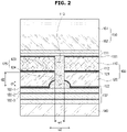
- FIG. 2 is a cross-sectional view of an ultrasonic probe in accordance with an embodiment of the present disclosure.
- the ultrasonic probe in accordance with an embodiment of the present disclosure includes a transducer layer 100, a matching layer 150 provided on a front side of the transducer layer 100, a sound absorption layer 140 provided on a rear side of the transducer layer 100, and a signal electrode 132 provided between the transducer layer 100 and the sound absorption layer 140.
- a magnetostrictive ultrasonic transducer using a magnetostrictive effect of a magnetic substance a capacitive micromachined ultrasonic transducer transmitting or receiving ultrasonic waves using the vibration of several hundreds or several thousands of micromachined thin films, or a piezoelectric ultrasonic transducer using a piezoelectric effect of a piezoelectric material may be used as a transducer.
- the piezoelectric ultrasonic transducer will be described as an embodiment of a transducer.
- piezoelectric effect Effects of a voltage being generated when mechanical pressure is applied to a certain material and a material being mechanically deformed when a voltage is applied thereto are respectively referred to as the piezoelectric effect and an inverse piezoelectric effect.
- a material having the effects is referred to as a piezoelectric material.
- the piezoelectric material is a material that converts electric energy into mechanical vibration energy and converts mechanical vibration energy into electric energy.
- the transducer layer 100 in accordance with an embodiment of the present disclosure includes a piezoelectric layer 110 formed of a piezoelectric material which generates ultrasonic waves by converting an electrical signal applied thereto into mechanical vibration, and a sound layer 120 provided on a rear side of the piezoelectric layer 110.
- Examples of the piezoelectric material of the piezoelectric layer 110 may include ceramic of lead zirconate titanate (PZT), PZMT single crystal formed of a solid solution of lead magnesium niobate and lead titanate, PZNT single crystal formed of a solid solution of lead zinc niobate and lead titanate, etc.
- PZT lead zirconate titanate
- PZMT PZMT single crystal formed of a solid solution of lead magnesium niobate and lead titanate
- PZNT single crystal formed of a solid solution of lead zinc niobate and lead titanate etc.
- the sound layer 120 may have higher acoustic impedance than that of the piezoelectric layer 110.
- the sound layer 120 may be formed of a material having electrical conductivity.
- a thickness of the sound layer 120 may be 1/2, 1/4, 1/8, or 1/16 of a wavelength of the piezoelectric material of the piezoelectric layer 110. That is, when the wavelength of the piezoelectric material of the piezoelectric layer 110 is ⁇ , the thickness of the sound layer 120 may be 1/2 ⁇ , 1/4 ⁇ , 1/8 ⁇ or 1/16 ⁇ .
- the sound layer 120 may be an acoustic reflector.
- the acoustic reflector may be provided in front of the sound absorption layer 140.
- the acoustic reflector may completely reflect ultrasonic waves propagating toward the sound absorption layer 140.
- a bandwidth and sensitivity of the ultrasonic probe may be increased using the acoustic reflector.
- the acoustic reflector may be formed of a material having very high acoustic impedance to completely reflect ultrasonic waves.
- the sound layer 120 may be formed of a material having very high acoustic impedance.
- the sound layer 120 may be formed of at least one of tungsten carbide and a graphite composite material.
- An electrode to which an electrical signal may be supplied may be formed on the front and rear surfaces of the transducer layer 100.
- a ground electrode 131 may be formed on the front surface of the transducer layer 100.
- a signal electrode 132 may be formed on the rear surface of the transducer layer 100.
- Each of the ground electrode 131 and the signal electrode 132 may be a flexible printed circuit board.
- electrodes may be formed a front surface and a rear surface of the piezoelectric layer 110.
- a first electrode 111 connected to the ground electrode 131 may be provided on the front surface of the piezoelectric layer 110
- a second electrode 112 electrically connected the signal electrode 132 may be provided on the rear surface of the piezoelectric layer 110.
- the first electrode 111 formed on the front surface of the piezoelectric layer 110 may be connected to the signal electrode 132
- the second electrode 112 formed on the rear surface of the piezoelectric layer 110 may be connected to the ground electrode 131.
- the sound layer 120 may include a third electrode 121 and a fourth electrode 122.
- the third electrode 121 may be formed on a front surface of the sound layer 120, and the fourth electrode 122 may be formed on a rear surface of the sound layer 120.
- the third electrode 121 and the fourth electrode 122 may be electrically connected. That is, the third electrode 121 and the fourth electrode 122 may be short-circuited.
- the third electrode 121 and the fourth electrode 122 are illustrated in FIG. 2 , but the present disclosure is not limited thereto.
- the sound layer 120 may not include the electrodes formed on the front and rear surfaces thereof. In this case, the sound layer 120 may be formed of a conductive material. When the sound layer 120 is formed of the conductive material, the sound layer 120 may be electrically connected to the second electrode 112 and the signal electrode 132 without the third electrode 121 and the fourth electrode 122.
- the matching layer 150 is provided on the front surface of the transducer layer 100.
- the matching layer 150 matches acoustic impedances of the transducer layer 100 and a subject by decreasing an impedance difference between the transducer layer 100 and the subject so that ultrasonic waves generated by the transducer layer 100 may be efficiently transmitted to the subject.
- the impedance of the matching layer 150 may have a median value between the acoustic impedance of the transducer layer 100 and the acoustic impedance of the subject.
- the impedance of the matching layer 150 may have a median value between an acoustic impedance of the piezoelectric layer 110 and the acoustic impedance of the subject.
- the matching layer 150 may include a plurality of matching layers to change acoustic impedance stepwise from the transducer layer 100 toward the subject. As illustrated in FIG. 2 , the matching layer 150 may include a first matching layer 151 and a second matching layer 152. The plurality of matching layers 150 may be formed of different materials. The matching layer 150 may be formed of glass or a resin material.
- a lens may be provided on a front surface of the matching layer 150.
- the lens may focus ultrasonic waves generated by the piezoelectric layer 110.
- the lens may be formed of a material, such as silicon or rubber, having substantially the same acoustic impedance as that of the subject.
- the lens may be a convex type lens of which a central part has a convex curved surface or may be a linear type lens having a flat surface.
- the sound absorption layer 140 may be provided on the rear side of the transducer layer 100.
- the sound absorption layer 140 may prevent distortion of an ultrasonic image by suppressing free vibration of the piezoelectric layer 110 to decrease a pulse width of ultrasonic waves and preventing the ultrasonic waves from unnecessarily propagating behind the piezoelectric layer 110.
- the sound absorption layer 140 may be formed of a material containing rubber to which epoxy resin, tungsten powder, etc. are added.
- the ultrasonic probe may be a multi-row probe.
- a single-row (1D) probe includes a plurality of elements as the transducer layer 100 is divided in an azimuth direction.
- the transducer layer 100 is not divided in a direction of elevation.
- the single-row probe has a physical focal zone due to lens curvature, and thus the focal zone is fixed. Accordingly, the single-row probe is limited in terms of the focal zone.
- the transducer layer 100 is divided in the direction of elevation, as well as the azimuth direction.
- an element of a 1.25D probe is divided into three parts in the direction of elevation
- an element of a 1.5D probe is divided into four parts in the direction of elevation
- an element of a 1.75D probe is divided into five parts in the direction of elevation. That is, the multi-row probes include elements arranged in three to five rows in the direction of elevation.
- a focusing region may be physically and electrically adjusted, and thus a high-resolution image of a wider region may be obtained.
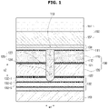
- FIG. 1 is a cross-sectional view of a structure of a conventional ultrasonic probe.
- the transducer layer 100 is divided by dicing in the direction of elevation.
- the transducer layer 100 includes the piezoelectric layer 110 and the sound layer 120, and thus the piezoelectric layer 110 and the sound layer 120 should be divided by dicing in the direction of elevation.
- the signal electrode 132 provided on the rear surface of the sound layer 120 may include a fifth electrode 132-1, a polyimide film 132-2, and a sixth electrode 132-3.
- a dicing thickness margin may be a thickness of the polyimide film 132-2.
- the multi-row may be formed by dividing the fifth electrode 132-1, whereas the wiring pattern of the signal electrode 132 is disconnected when the sixth electrode 132-3 is divided.
- the polyimide film 132-2 may have a thickness of about 12 ⁇ m.
- a thickness margin when the transducer layer 100 is divided in the direction of elevation may be 12 ⁇ m, corresponding to a thickness of the polyimide film 132-2. That is, a thickness margin between the transducer layer 100 and the signal electrode 132 is very small. Therefore, the sound layer 120 was not divided when a cutting depth of the dicing was extremely small, and a wiring pattern of the signal electrode 132 was disconnected to cause a defect when the cutting depth was extremely large. Conventionally, as described above, since a cutting thickness margin of the dicing was extremely small, an error rate was high during manufacture of the multi-row probe. Furthermore, an intermediate process inspection could not be performed, and thus failure costs were also high.
- a process error rate of the multi-row probe is decreased by simple processing of the transducer layer 100.
- the piezoelectric layer 110 in accordance with an embodiment of the present disclosure includes a kerf 113 and the sound layer 120 includes a funnel 125.
- the piezoelectric layer 110 includes the kerf 113 configured to divide the piezoelectric layer 110 in the direction of elevation.
- the kerf 113 is formed using a dicing process. Although only one kerf 113 is illustrated in the drawings, two or more kerfs 113 may be formed to be spaced apart from each other in the direction of elevation. In order to manufacture a 1.25D probe, two kerfs 113 may be formed. In order to manufacture a 1.5D probe, three kerfs 113 may be formed. In order to manufacture a 1.75D probe, four kerfs 113 may be formed.
- the sound layer 120 includes the funnel 125.
- the funnel 125 is provided to be connected to the kerf 113 formed on the piezoelectric layer 110.
- the funnel 125 is provided to divide the sound layer 120 in the direction of elevation.
- the funnel 125 includes a first section 123 connected to the kerf 113 and a second section 124 connected to the signal electrode 132.
- the first section 123 is formed at a location corresponding to the kerf 113 in order to be connected to the kerf 113.
- a width of the first section 123 is the same as that of the kerf 113 since the first section 123 and the kerf 113 are formed together using the dicing process.
- the second section 124 is concave toward the inside of the sound layer 120.
- the second section 124 is formed on the sound layer 120 before the first section 123 is formed. That is, the second section 124 is formed on the sound layer 120 by preprocessing.
- the second section 124 is formed only on the sound layer 120, and is not formed on the flexible printed circuit board (namely, signal electrode) 132. Similar to the kerf 113, two second sections 124 are previously formed in the case of a 1.25D probe. Three second sections 124 are previously formed in the case of a 1.5D probe. Four second sections 124 are previously formed in the case of a 1.75D probe.
- the funnel 125 is provided by forming the first section 123 on the preprocessed second section 124 using the dicing process. As will be described below, the second section 124 is provided to secure a cutting margin when an element is divided. Thus, the second section 124 is formed only on the sound layer 120 and is not formed on the flexible printed circuit board 132.
- the first section 123 and the kerf 113 may be formed together using the dicing process.
- the second section 124 decreases an error rate during manufacture of the multi-row probe.
- the second section 124 increases a thickness margin when an element is divided.
- a cutting margin is secured when an element is divided.
- an element cannot be divided when a cutting depth is extremely small, and the signal electrode 132 may be inadvertently cut and an error may occur when the cutting depth is extremely large.
- the second section 124 is formed in advance on the sound layer 120, a thickness margin corresponding to a depth d1 of the second section 124 is secured. As the thickness margin increases, a cutting error rate decreases. When the cutting error decreases, failure costs decreases.
- a width w1 of the first section 123 is less than a width w2 of the second section 124.
- the width w1 of the first section is equal to a dicing thickness.
- a thickness margin is secured in the azimuth direction during the dicing process.
- the depth d1 of the second section 124 is less than a thickness d2 of the sound layer 120.
- the kerf 113 is provided to have a constant width in a direction extending from the front side of the piezoelectric layer 110 to the rear side thereof.
- the first section 123 is provided to have a constant width in a direction extending from the front side of the sound layer 120 to the rear side thereof.
- the second section 124 is provided such that a width thereof changes in the direction extending from the front side of the sound layer 120 to the rear side thereof.
- the width of the second section 124 increases as the distance between the second section 124 and the signal electrode 132 decreases.
- the second section 124 has a semicircular cross section.
- the depth d1 of the second section 124 at a point at which the second section 124 and the first section 123 meet each other may be a maximum depth of the second section 124.
- the first electrode 132-1 of the signal electrode 132 is divided by pre-processing.
- the pre-processing may include various methods. For example, when a flexible printed circuit board is formed, a region therein corresponding to the funnel 125 may be formed without the first electrode 132-1.
- FIG. 3 is a cross-sectional view of an ultrasonic probe in accordance with an example not forming part of the invention. A description of parts of the ultrasonic probe illustrated in FIG. 3 which are the same as those in prior description will be omitted here.
- a funnel 125 has a structure different from that in the embodiment of FIG. 2 . More specifically, a width w2 of a second section 124 of the funnel 125 may be constant in a direction extending from a front side of a sound layer 120 to a rear side thereof. The second section 124 may have a rectangular cross section.
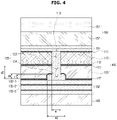
- FIG. 4 is a cross-sectional view of an ultrasonic probe in accordance with another example not forming part of the invention. A description of parts of the ultrasonic probe illustrated in FIG. 4 which are the same as those in the above description will be omitted here.
- a funnel 125 may have a structure different from those in the embodiment of FIG. 2 and example of FIG. 3 .
- a depth d at a point at which a second section 124 and a first section 123 of the funnel 125 meet each other may be different from a maximum depth dm of the second section 124.
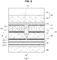
- FIG. 5 is a cross-sectional view of an ultrasonic probe in accordance with another example not forming part of the invention. A description of parts of the ultrasonic probe illustrated in FIG. 5 which are the same as those in the above description will be omitted here.
- a funnel 125 may have a structure different from those in the embodiment of FIG. 2 and examples of FIGS. 3 and 4 .
- a width w2 of a second section of the funnel 125 may be less than a width w1 of a first section thereof.
- the width w2 of the second section may be constant in a direction extending from a front side of a sound layer 120 to a rear side thereof.
- a width of the first section 123 may change in the direction extending from the front side of the sound layer 120 to the rear side thereof.
- FIGS. 2 to 5 illustrate that the funnel 125 has bilateral symmetry, embodiments and examples are not limited thereto.
- the funnel 125 may have bilateral asymmetry due to an error during a manufacturing process.
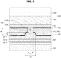
- FIG. 6 is a cross-sectional view of an ultrasonic probe in accordance with another example not forming part of the invention.
- a transducer layer 100 of the ultrasonic probe may include only a piezoelectric layer 110. That is, in the example of FIG. 6 , the transducer layer 100 does not include a sound layer.
- a funnel 115 may be formed on the piezoelectric layer 110.
- the funnel 115 may include a first section 113 and a second section 114, similar to those in the embodiment of FIG.2 and examples of FIGS. 3 to 5 .
- a width w1 of the first section 113 may be less than a width w2 of the second section 114.
- the width w1 of the first section 113 may be constant in a direction extending from a front side of the piezoelectric layer 110 to a rear side thereof.
- the width w2 of the second section 114 may change in the direction extending from the front side of the piezoelectric layer 110 to the rear side thereof.
- the second section 114 may have a maximum depth d1 at a point at which the first section 113 and the second section 114 meet each other. A depth of the second section 114 may decrease toward an outer side of the funnel 115.
- FIG. 7 is a cross-sectional view of an ultrasonic probe in accordance with another example not forming part of the invention.
- a sound layer is not provided as in the example of FIG. 6 .
- a funnel 115 may be formed on a piezoelectric layer 110.
- a width w1 of a first section 213 of the funnel 115 may be less than a width w2 of a second section 114 thereof.
- the width w1 of the first section 213 and the width w2 of the second section 114 may each be constant in a direction extending from a front side of the piezoelectric layer 110 to a rear side thereof.
- a depth d1 of the second section 114 may be constant.
- FIG. 8 is a cross-sectional view of an ultrasonic probe in accordance with another example not forming part of the invention.
- a sound layer is not provided as in the examples of FIGS. 6 and 7 .
- a funnel 115 may be formed on a piezoelectric layer 110.
- a width w1 of a first section 113 of the funnel 115 may be less than a width w2 of a second section 114 thereof.
- the width w1 of the first section 113 may be constant in a direction extending from a front side of the piezoelectric layer 110 to a rear side thereof.
- the width w2 of the second section 114 may change in the direction extending from the front side of the piezoelectric layer 110 to the rear side thereof.
- the second section 114 may not have a maximum depth dm at a point at which the first section 113 and the second section 114 meet each other.
- a depth d1 at the point at which the first section 113 and the second section 114 meet each other may be different from the maximum depth dm of the second section 114.
- a depth of the second section 114 may not be constant.
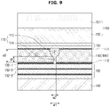
- FIG. 9 is a cross-sectional view of an ultrasonic probe in accordance with another example not forming part of the invention.
- a sound layer is not provided as in the examples of FIGS. 6 to 8 .
- a funnel 115 may be formed on a piezoelectric layer 110.
- the funnel 115 may include a first section 113 and a second section 114.
- a width w2 of the second section 114 may be less than a width w1 of the first section 113.
- the width w1 of the first section 113 may change in a direction extending from a front side of the piezoelectric layer 110 to a rear side thereof.
- the width w1 of the first section 113 may decrease from the front side of the piezoelectric layer 110 to the rear side thereof.
- the width w2 of the second section 114 may be constant in the direction extending from the front side of the piezoelectric layer 110 to the rear side thereof.
- the funnel 115 is illustrated as having bilateral symmetry in FIGS. 6 to 9 , examples are not limited thereto.
- the funnel 115 may have bilateral asymmetry due to an error during a manufacturing process.
Landscapes
- Health & Medical Sciences (AREA)
- Life Sciences & Earth Sciences (AREA)
- Engineering & Computer Science (AREA)
- General Health & Medical Sciences (AREA)
- Physics & Mathematics (AREA)
- Pathology (AREA)
- Surgery (AREA)
- Public Health (AREA)
- Biomedical Technology (AREA)
- Heart & Thoracic Surgery (AREA)
- Medical Informatics (AREA)
- Molecular Biology (AREA)
- Nuclear Medicine, Radiotherapy & Molecular Imaging (AREA)
- Animal Behavior & Ethology (AREA)
- Biophysics (AREA)
- Radiology & Medical Imaging (AREA)
- Veterinary Medicine (AREA)
- Gynecology & Obstetrics (AREA)
- Mechanical Engineering (AREA)
- Chemical & Material Sciences (AREA)
- Analytical Chemistry (AREA)
- Biochemistry (AREA)
- General Physics & Mathematics (AREA)
- Immunology (AREA)
- Ultra Sonic Daignosis Equipment (AREA)
- Transducers For Ultrasonic Waves (AREA)
Claims (6)
- Ultraschallsonde, die Folgendes umfasst:eine piezoelektrische Schicht (110), die so konfiguriert ist, dass sie Ultraschallwellen erzeugt;eine Schallschicht (120), die auf einer Rückseite der piezoelektrischen Schicht (110) vorgesehen ist;eine flexible Leiterplatte (132), die auf einer Rückseite der Schallschicht (120) vorgesehen ist; undeine Schallabsorptionsschicht (140), die so konfiguriert ist, dass sie die von der piezoelektrischen Schicht (110) erzeugten und sich in Richtung einer Rückseite der Ultraschallsonde ausbreitenden Ultraschallwellen absorbiert, wobei die Schallabsorptionsschicht (140) auf einer Rückseite der flexiblen Leiterplatte (132) vorgesehen ist,wobei die piezoelektrische Schicht (110) eine Kerbe (113) umfasst, die so konfiguriert ist, dass sie die piezoelektrische Schicht (110) in einer Höhenrichtung teilt,wobei die Schallschicht (120) einen Trichter (125) umfasst, der sich in einer Richtung erstreckt, die sich von einer Vorderseite der Schallschicht (120) zu der Rückseite der Schallschicht (120) erstreckt, um die Schallschicht (120) zu teilen; undwobei die flexible Leiterplatte (132) eine Vielzahl von geteilten ersten Elektroden (132-1), eine zweite Elektrode (132-3) und einen zwischen der Vielzahl von geteilten ersten Elektroden (132-1) und der zweiten Elektrode (132-3) angeordneten Polyimidfilm (132-2) enthält, wobei die Ultraschallsonde dadurch gekennzeichnet ist, dass der Trichter (125) Folgendes umfasst:einen ersten Abschnitt (123), der mit der piezoelektrischen Schicht (110) verbunden ist; undeinen zweiten Abschnitt (124), der mit der flexiblen Leiterplatte (132) verbunden ist,wobei der erste Abschnitt (123) an einer Stelle vorgesehen ist, die der Kerbe (113) entspricht, um mit der Kerbe (113) verbunden zu werden, wobei eine Breite der Kerbe (113) die gleiche wie die des ersten Abschnitts ist, undwobei die Breite des ersten Abschnitts (123) konstant und kleiner als die Breite des zweiten Abschnitts (124) ist, die zunimmt, wenn der Abstand zwischen dem zweiten Abschnitt und den Elektroden abnimmt, so dass der zweite Abschnitt (124) einen halbkreisförmigen Querschnitt aufweist.
- Ultraschallsonde nach Anspruch 1, wobei die Schallschicht (120) eine höhere akustische Impedanz als die piezoelektrische Schicht (110) aufweist.
- Ultraschallsonde nach Anspruch 1, wobei die Schallschicht (120) eine elektrische Leitfähigkeit aufweist.
- Ultraschallsonde nach Anspruch 1, wobei die Schallschicht (120) Wolframcarbid und/oder ein Graphitverbundmaterial umfasst.
- Ultraschallsonde nach Anspruch 1, wobei die Schallschicht (120) eine Breite aufweist, die 1/2, 1/4, 1/8 oder 1/16 einer Wellenlänge der piezoelektrischen Schicht (110) beträgt.
- Ultraschallsonde nach Anspruch 1, wobei die Anzahl der Kerben zwei oder mehr beträgt und die Anzahl der Trichter zwei oder mehr beträgt.
Applications Claiming Priority (1)
| Application Number | Priority Date | Filing Date | Title |
|---|---|---|---|
| KR1020170022835A KR102717595B1 (ko) | 2017-02-21 | 2017-02-21 | 초음파 프로브 |
Publications (2)
| Publication Number | Publication Date |
|---|---|
| EP3363549A1 EP3363549A1 (de) | 2018-08-22 |
| EP3363549B1 true EP3363549B1 (de) | 2022-04-06 |
Family
ID=61249580
Family Applications (1)
| Application Number | Title | Priority Date | Filing Date |
|---|---|---|---|
| EP18157636.4A Active EP3363549B1 (de) | 2017-02-21 | 2018-02-20 | Ultraschallsonde |
Country Status (4)
| Country | Link |
|---|---|
| US (1) | US10932755B2 (de) |
| EP (1) | EP3363549B1 (de) |
| KR (1) | KR102717595B1 (de) |
| CN (1) | CN108459085B (de) |
Families Citing this family (6)
| Publication number | Priority date | Publication date | Assignee | Title |
|---|---|---|---|---|
| KR20200108642A (ko) * | 2019-03-11 | 2020-09-21 | 삼성메디슨 주식회사 | 초음파 프로브 및 그 제조 방법 |
| CN109998690A (zh) * | 2019-04-22 | 2019-07-12 | 青岛市市立医院 | 一种多功能肠胃外科手术操作平台 |
| KR20210105023A (ko) * | 2020-02-18 | 2021-08-26 | 삼성메디슨 주식회사 | 초음파 프로브 및 그 제조방법 |
| KR102802030B1 (ko) * | 2020-04-22 | 2025-05-02 | 삼성메디슨 주식회사 | 초음파 프로브 |
| KR102623559B1 (ko) * | 2021-02-10 | 2024-01-11 | 주식회사 에프씨유 | 초음파 프로브 |
| KR102660312B1 (ko) * | 2021-10-22 | 2024-04-24 | 한국과학기술원 | 임피던스 정합 패턴을 내장한 다층 유연성 인쇄회로 기판 및 초음파 소자 모듈 |
Family Cites Families (17)
| Publication number | Priority date | Publication date | Assignee | Title |
|---|---|---|---|---|
| US5311095A (en) * | 1992-05-14 | 1994-05-10 | Duke University | Ultrasonic transducer array |
| US5704105A (en) | 1996-09-04 | 1998-01-06 | General Electric Company | Method of manufacturing multilayer array ultrasonic transducers |
| US5882309A (en) | 1997-05-07 | 1999-03-16 | General Electric Company | Multi-row ultrasonic transducer array with uniform elevator beamwidth |
| US6656124B2 (en) | 2001-10-15 | 2003-12-02 | Vermon | Stack based multidimensional ultrasonic transducer array |
| JP4310586B2 (ja) * | 2003-01-23 | 2009-08-12 | 株式会社日立メディコ | 超音波探触子及び超音波診断装置 |
| WO2007017780A2 (en) * | 2005-08-05 | 2007-02-15 | Koninklijke Philips Electronics N.V. | Curved two-dimensional array transducer |
| KR101064601B1 (ko) | 2009-02-10 | 2011-09-15 | 주식회사 휴먼스캔 | 초음파 탐촉자, 초음파 영상 장치 및 그의 제조 방법 |
| JP2011250119A (ja) * | 2010-05-26 | 2011-12-08 | Toshiba Corp | 超音波プローブ |
| JP5699690B2 (ja) | 2011-03-03 | 2015-04-15 | コニカミノルタ株式会社 | 超音波探触子の製造方法 |
| KR101269459B1 (ko) * | 2011-12-13 | 2013-05-30 | 삼성전자주식회사 | 초음파 프로브 및 그 제조방법 |
| KR101354604B1 (ko) * | 2012-01-16 | 2014-01-23 | 삼성메디슨 주식회사 | 초음파 프로브 및 그 제조방법 |
| JP6102622B2 (ja) * | 2013-08-07 | 2017-03-29 | コニカミノルタ株式会社 | 超音波探触子 |
| KR102107729B1 (ko) * | 2013-08-19 | 2020-05-07 | 삼성메디슨 주식회사 | 초음파 프로브 및 그 제조 방법 |
| KR101613413B1 (ko) * | 2013-12-09 | 2016-04-19 | 삼성메디슨 주식회사 | 초음파 프로브 및 그 제조방법 |
| KR102457217B1 (ko) * | 2014-12-26 | 2022-10-21 | 삼성메디슨 주식회사 | 프로브 및 프로브의 제조방법 |
| KR20170087632A (ko) * | 2016-01-21 | 2017-07-31 | 삼성메디슨 주식회사 | 초음파 프로브 및 초음파 프로브의 제조 방법 |
| US10347818B2 (en) * | 2016-03-31 | 2019-07-09 | General Electric Company | Method for manufacturing ultrasound transducers |
-
2017
- 2017-02-21 KR KR1020170022835A patent/KR102717595B1/ko active Active
-
2018
- 2018-01-11 US US15/868,637 patent/US10932755B2/en active Active
- 2018-02-20 EP EP18157636.4A patent/EP3363549B1/de active Active
- 2018-02-22 CN CN201810153790.5A patent/CN108459085B/zh active Active
Non-Patent Citations (1)
| Title |
|---|
| None * |
Also Published As
| Publication number | Publication date |
|---|---|
| CN108459085A (zh) | 2018-08-28 |
| EP3363549A1 (de) | 2018-08-22 |
| KR20180096298A (ko) | 2018-08-29 |
| CN108459085B (zh) | 2022-06-24 |
| KR102717595B1 (ko) | 2024-10-16 |
| US20180235575A1 (en) | 2018-08-23 |
| US10932755B2 (en) | 2021-03-02 |
Similar Documents
| Publication | Publication Date | Title |
|---|---|---|
| EP3363549B1 (de) | Ultraschallsonde | |
| US9203012B2 (en) | Ultrasound probe and manufacturing method thereof | |
| RU2419388C2 (ru) | Ультразвуковой зонд | |
| US8319399B2 (en) | Ultrasound probe | |
| KR101354604B1 (ko) | 초음파 프로브 및 그 제조방법 | |
| US20130200755A1 (en) | Ultrasonic probe and manufacturing method thereof | |
| US20090069691A1 (en) | Ultrasonic probe | |
| US9445782B2 (en) | Ultrasonic probe and manufacturing method thereof | |
| CN113331865B (zh) | 超声探头及制造超声探头的方法 | |
| EP2881937A2 (de) | Ultraschall-Diagnoseinstrument und Herstellungsverfahren dafür | |
| US11806191B2 (en) | Phased array transducers and wafer scale manufacturing for making the same | |
| EP3510934A1 (de) | Ultraschallsonde | |
| US20140292147A1 (en) | Ultrasonic probe and manufacturing method thereof | |
| US20190393405A1 (en) | Ultrasonic probe and manufacturing method thereof | |
| US9254119B2 (en) | Ultrasound probe and manufacturing method thereof | |
| Chen et al. | Recent results from dual-layer array transducers for 3-d imaging | |
| KR20190118866A (ko) | 위상 배열 구조를 갖는 초음파 프로브 |
Legal Events
| Date | Code | Title | Description |
|---|---|---|---|
| PUAI | Public reference made under article 153(3) epc to a published international application that has entered the european phase |
Free format text: ORIGINAL CODE: 0009012 |
|
| STAA | Information on the status of an ep patent application or granted ep patent |
Free format text: STATUS: THE APPLICATION HAS BEEN PUBLISHED |
|
| AK | Designated contracting states |
Kind code of ref document: A1 Designated state(s): AL AT BE BG CH CY CZ DE DK EE ES FI FR GB GR HR HU IE IS IT LI LT LU LV MC MK MT NL NO PL PT RO RS SE SI SK SM TR |
|
| AX | Request for extension of the european patent |
Extension state: BA ME |
|
| STAA | Information on the status of an ep patent application or granted ep patent |
Free format text: STATUS: REQUEST FOR EXAMINATION WAS MADE |
|
| 17P | Request for examination filed |
Effective date: 20190221 |
|
| RBV | Designated contracting states (corrected) |
Designated state(s): AL AT BE BG CH CY CZ DE DK EE ES FI FR GB GR HR HU IE IS IT LI LT LU LV MC MK MT NL NO PL PT RO RS SE SI SK SM TR |
|
| STAA | Information on the status of an ep patent application or granted ep patent |
Free format text: STATUS: EXAMINATION IS IN PROGRESS |
|
| 17Q | First examination report despatched |
Effective date: 20200713 |
|
| GRAP | Despatch of communication of intention to grant a patent |
Free format text: ORIGINAL CODE: EPIDOSNIGR1 |
|
| STAA | Information on the status of an ep patent application or granted ep patent |
Free format text: STATUS: GRANT OF PATENT IS INTENDED |
|
| INTG | Intention to grant announced |
Effective date: 20210927 |
|
| GRAS | Grant fee paid |
Free format text: ORIGINAL CODE: EPIDOSNIGR3 |
|
| GRAA | (expected) grant |
Free format text: ORIGINAL CODE: 0009210 |
|
| STAA | Information on the status of an ep patent application or granted ep patent |
Free format text: STATUS: THE PATENT HAS BEEN GRANTED |
|
| AK | Designated contracting states |
Kind code of ref document: B1 Designated state(s): AL AT BE BG CH CY CZ DE DK EE ES FI FR GB GR HR HU IE IS IT LI LT LU LV MC MK MT NL NO PL PT RO RS SE SI SK SM TR |
|
| REG | Reference to a national code |
Ref country code: GB Ref legal event code: FG4D |
|
| REG | Reference to a national code |
Ref country code: CH Ref legal event code: EP |
|
| REG | Reference to a national code |
Ref country code: AT Ref legal event code: REF Ref document number: 1480815 Country of ref document: AT Kind code of ref document: T Effective date: 20220415 |
|
| REG | Reference to a national code |
Ref country code: IE Ref legal event code: FG4D |
|
| REG | Reference to a national code |
Ref country code: DE Ref legal event code: R096 Ref document number: 602018033213 Country of ref document: DE |
|
| REG | Reference to a national code |
Ref country code: LT Ref legal event code: MG9D |
|
| REG | Reference to a national code |
Ref country code: NL Ref legal event code: MP Effective date: 20220406 |
|
| REG | Reference to a national code |
Ref country code: AT Ref legal event code: MK05 Ref document number: 1480815 Country of ref document: AT Kind code of ref document: T Effective date: 20220406 |
|
| PG25 | Lapsed in a contracting state [announced via postgrant information from national office to epo] |
Ref country code: NL Free format text: LAPSE BECAUSE OF FAILURE TO SUBMIT A TRANSLATION OF THE DESCRIPTION OR TO PAY THE FEE WITHIN THE PRESCRIBED TIME-LIMIT Effective date: 20220406 |
|
| PG25 | Lapsed in a contracting state [announced via postgrant information from national office to epo] |
Ref country code: SE Free format text: LAPSE BECAUSE OF FAILURE TO SUBMIT A TRANSLATION OF THE DESCRIPTION OR TO PAY THE FEE WITHIN THE PRESCRIBED TIME-LIMIT Effective date: 20220406 Ref country code: PT Free format text: LAPSE BECAUSE OF FAILURE TO SUBMIT A TRANSLATION OF THE DESCRIPTION OR TO PAY THE FEE WITHIN THE PRESCRIBED TIME-LIMIT Effective date: 20220808 Ref country code: NO Free format text: LAPSE BECAUSE OF FAILURE TO SUBMIT A TRANSLATION OF THE DESCRIPTION OR TO PAY THE FEE WITHIN THE PRESCRIBED TIME-LIMIT Effective date: 20220706 Ref country code: LT Free format text: LAPSE BECAUSE OF FAILURE TO SUBMIT A TRANSLATION OF THE DESCRIPTION OR TO PAY THE FEE WITHIN THE PRESCRIBED TIME-LIMIT Effective date: 20220406 Ref country code: HR Free format text: LAPSE BECAUSE OF FAILURE TO SUBMIT A TRANSLATION OF THE DESCRIPTION OR TO PAY THE FEE WITHIN THE PRESCRIBED TIME-LIMIT Effective date: 20220406 Ref country code: GR Free format text: LAPSE BECAUSE OF FAILURE TO SUBMIT A TRANSLATION OF THE DESCRIPTION OR TO PAY THE FEE WITHIN THE PRESCRIBED TIME-LIMIT Effective date: 20220707 Ref country code: FI Free format text: LAPSE BECAUSE OF FAILURE TO SUBMIT A TRANSLATION OF THE DESCRIPTION OR TO PAY THE FEE WITHIN THE PRESCRIBED TIME-LIMIT Effective date: 20220406 Ref country code: ES Free format text: LAPSE BECAUSE OF FAILURE TO SUBMIT A TRANSLATION OF THE DESCRIPTION OR TO PAY THE FEE WITHIN THE PRESCRIBED TIME-LIMIT Effective date: 20220406 Ref country code: BG Free format text: LAPSE BECAUSE OF FAILURE TO SUBMIT A TRANSLATION OF THE DESCRIPTION OR TO PAY THE FEE WITHIN THE PRESCRIBED TIME-LIMIT Effective date: 20220706 Ref country code: AT Free format text: LAPSE BECAUSE OF FAILURE TO SUBMIT A TRANSLATION OF THE DESCRIPTION OR TO PAY THE FEE WITHIN THE PRESCRIBED TIME-LIMIT Effective date: 20220406 |
|
| PG25 | Lapsed in a contracting state [announced via postgrant information from national office to epo] |
Ref country code: RS Free format text: LAPSE BECAUSE OF FAILURE TO SUBMIT A TRANSLATION OF THE DESCRIPTION OR TO PAY THE FEE WITHIN THE PRESCRIBED TIME-LIMIT Effective date: 20220406 Ref country code: PL Free format text: LAPSE BECAUSE OF FAILURE TO SUBMIT A TRANSLATION OF THE DESCRIPTION OR TO PAY THE FEE WITHIN THE PRESCRIBED TIME-LIMIT Effective date: 20220406 Ref country code: LV Free format text: LAPSE BECAUSE OF FAILURE TO SUBMIT A TRANSLATION OF THE DESCRIPTION OR TO PAY THE FEE WITHIN THE PRESCRIBED TIME-LIMIT Effective date: 20220406 Ref country code: IS Free format text: LAPSE BECAUSE OF FAILURE TO SUBMIT A TRANSLATION OF THE DESCRIPTION OR TO PAY THE FEE WITHIN THE PRESCRIBED TIME-LIMIT Effective date: 20220806 |
|
| REG | Reference to a national code |
Ref country code: DE Ref legal event code: R097 Ref document number: 602018033213 Country of ref document: DE |
|
| PG25 | Lapsed in a contracting state [announced via postgrant information from national office to epo] |
Ref country code: SM Free format text: LAPSE BECAUSE OF FAILURE TO SUBMIT A TRANSLATION OF THE DESCRIPTION OR TO PAY THE FEE WITHIN THE PRESCRIBED TIME-LIMIT Effective date: 20220406 Ref country code: SK Free format text: LAPSE BECAUSE OF FAILURE TO SUBMIT A TRANSLATION OF THE DESCRIPTION OR TO PAY THE FEE WITHIN THE PRESCRIBED TIME-LIMIT Effective date: 20220406 Ref country code: RO Free format text: LAPSE BECAUSE OF FAILURE TO SUBMIT A TRANSLATION OF THE DESCRIPTION OR TO PAY THE FEE WITHIN THE PRESCRIBED TIME-LIMIT Effective date: 20220406 Ref country code: EE Free format text: LAPSE BECAUSE OF FAILURE TO SUBMIT A TRANSLATION OF THE DESCRIPTION OR TO PAY THE FEE WITHIN THE PRESCRIBED TIME-LIMIT Effective date: 20220406 Ref country code: DK Free format text: LAPSE BECAUSE OF FAILURE TO SUBMIT A TRANSLATION OF THE DESCRIPTION OR TO PAY THE FEE WITHIN THE PRESCRIBED TIME-LIMIT Effective date: 20220406 Ref country code: CZ Free format text: LAPSE BECAUSE OF FAILURE TO SUBMIT A TRANSLATION OF THE DESCRIPTION OR TO PAY THE FEE WITHIN THE PRESCRIBED TIME-LIMIT Effective date: 20220406 |
|
| PLBE | No opposition filed within time limit |
Free format text: ORIGINAL CODE: 0009261 |
|
| STAA | Information on the status of an ep patent application or granted ep patent |
Free format text: STATUS: NO OPPOSITION FILED WITHIN TIME LIMIT |
|
| 26N | No opposition filed |
Effective date: 20230110 |
|
| PG25 | Lapsed in a contracting state [announced via postgrant information from national office to epo] |
Ref country code: AL Free format text: LAPSE BECAUSE OF FAILURE TO SUBMIT A TRANSLATION OF THE DESCRIPTION OR TO PAY THE FEE WITHIN THE PRESCRIBED TIME-LIMIT Effective date: 20220406 |
|
| PG25 | Lapsed in a contracting state [announced via postgrant information from national office to epo] |
Ref country code: SI Free format text: LAPSE BECAUSE OF FAILURE TO SUBMIT A TRANSLATION OF THE DESCRIPTION OR TO PAY THE FEE WITHIN THE PRESCRIBED TIME-LIMIT Effective date: 20220406 |
|
| PG25 | Lapsed in a contracting state [announced via postgrant information from national office to epo] |
Ref country code: MC Free format text: LAPSE BECAUSE OF FAILURE TO SUBMIT A TRANSLATION OF THE DESCRIPTION OR TO PAY THE FEE WITHIN THE PRESCRIBED TIME-LIMIT Effective date: 20220406 |
|
| REG | Reference to a national code |
Ref country code: CH Ref legal event code: PL |
|
| REG | Reference to a national code |
Ref country code: BE Ref legal event code: MM Effective date: 20230228 |
|
| GBPC | Gb: european patent ceased through non-payment of renewal fee |
Effective date: 20230220 |
|
| PG25 | Lapsed in a contracting state [announced via postgrant information from national office to epo] |
Ref country code: LU Free format text: LAPSE BECAUSE OF NON-PAYMENT OF DUE FEES Effective date: 20230220 Ref country code: LI Free format text: LAPSE BECAUSE OF NON-PAYMENT OF DUE FEES Effective date: 20230228 Ref country code: CH Free format text: LAPSE BECAUSE OF NON-PAYMENT OF DUE FEES Effective date: 20230228 |
|
| REG | Reference to a national code |
Ref country code: IE Ref legal event code: MM4A |
|
| PG25 | Lapsed in a contracting state [announced via postgrant information from national office to epo] |
Ref country code: GB Free format text: LAPSE BECAUSE OF NON-PAYMENT OF DUE FEES Effective date: 20230220 |
|
| PG25 | Lapsed in a contracting state [announced via postgrant information from national office to epo] |
Ref country code: IE Free format text: LAPSE BECAUSE OF NON-PAYMENT OF DUE FEES Effective date: 20230220 Ref country code: GB Free format text: LAPSE BECAUSE OF NON-PAYMENT OF DUE FEES Effective date: 20230220 |
|
| PG25 | Lapsed in a contracting state [announced via postgrant information from national office to epo] |
Ref country code: BE Free format text: LAPSE BECAUSE OF NON-PAYMENT OF DUE FEES Effective date: 20230228 |
|
| PG25 | Lapsed in a contracting state [announced via postgrant information from national office to epo] |
Ref country code: BG Free format text: LAPSE BECAUSE OF FAILURE TO SUBMIT A TRANSLATION OF THE DESCRIPTION OR TO PAY THE FEE WITHIN THE PRESCRIBED TIME-LIMIT Effective date: 20220406 |
|
| PG25 | Lapsed in a contracting state [announced via postgrant information from national office to epo] |
Ref country code: BG Free format text: LAPSE BECAUSE OF FAILURE TO SUBMIT A TRANSLATION OF THE DESCRIPTION OR TO PAY THE FEE WITHIN THE PRESCRIBED TIME-LIMIT Effective date: 20220406 |
|
| PGFP | Annual fee paid to national office [announced via postgrant information from national office to epo] |
Ref country code: DE Payment date: 20250106 Year of fee payment: 8 |
|
| PGFP | Annual fee paid to national office [announced via postgrant information from national office to epo] |
Ref country code: FR Payment date: 20250107 Year of fee payment: 8 |
|
| PGFP | Annual fee paid to national office [announced via postgrant information from national office to epo] |
Ref country code: IT Payment date: 20250107 Year of fee payment: 8 |
|
| PG25 | Lapsed in a contracting state [announced via postgrant information from national office to epo] |
Ref country code: CY Free format text: LAPSE BECAUSE OF FAILURE TO SUBMIT A TRANSLATION OF THE DESCRIPTION OR TO PAY THE FEE WITHIN THE PRESCRIBED TIME-LIMIT; INVALID AB INITIO Effective date: 20180220 |
|
| PG25 | Lapsed in a contracting state [announced via postgrant information from national office to epo] |
Ref country code: HU Free format text: LAPSE BECAUSE OF FAILURE TO SUBMIT A TRANSLATION OF THE DESCRIPTION OR TO PAY THE FEE WITHIN THE PRESCRIBED TIME-LIMIT; INVALID AB INITIO Effective date: 20180220 |