EP3363468A1 - Fluid sterilization device and fluid sterilization method - Google Patents
Fluid sterilization device and fluid sterilization method Download PDFInfo
- Publication number
- EP3363468A1 EP3363468A1 EP16855204.0A EP16855204A EP3363468A1 EP 3363468 A1 EP3363468 A1 EP 3363468A1 EP 16855204 A EP16855204 A EP 16855204A EP 3363468 A1 EP3363468 A1 EP 3363468A1
- Authority
- EP
- European Patent Office
- Prior art keywords
- fluid
- straight pipe
- longitudinal direction
- flow passage
- light
- Prior art date
- Legal status (The legal status is an assumption and is not a legal conclusion. Google has not performed a legal analysis and makes no representation as to the accuracy of the status listed.)
- Withdrawn
Links
Images



Classifications
-
- A—HUMAN NECESSITIES
- A61—MEDICAL OR VETERINARY SCIENCE; HYGIENE
- A61L—METHODS OR APPARATUS FOR STERILISING MATERIALS OR OBJECTS IN GENERAL; DISINFECTION, STERILISATION OR DEODORISATION OF AIR; CHEMICAL ASPECTS OF BANDAGES, DRESSINGS, ABSORBENT PADS OR SURGICAL ARTICLES; MATERIALS FOR BANDAGES, DRESSINGS, ABSORBENT PADS OR SURGICAL ARTICLES
- A61L2/00—Disinfection or sterilisation of materials or objects, in general; Accessories therefor
- A61L2/02—Disinfection or sterilisation of materials or objects, in general; Accessories therefor using physical processes
- A61L2/08—Radiation
- A61L2/10—Ultraviolet [UV] radiation
-
- A—HUMAN NECESSITIES
- A61—MEDICAL OR VETERINARY SCIENCE; HYGIENE
- A61L—METHODS OR APPARATUS FOR STERILISING MATERIALS OR OBJECTS IN GENERAL; DISINFECTION, STERILISATION OR DEODORISATION OF AIR; CHEMICAL ASPECTS OF BANDAGES, DRESSINGS, ABSORBENT PADS OR SURGICAL ARTICLES; MATERIALS FOR BANDAGES, DRESSINGS, ABSORBENT PADS OR SURGICAL ARTICLES
- A61L9/00—Disinfection, sterilisation or deodorisation of air
- A61L9/16—Disinfection, sterilisation or deodorisation of air using physical phenomena
- A61L9/18—Radiation
- A61L9/20—Ultraviolet radiation
-
- C—CHEMISTRY; METALLURGY
- C02—TREATMENT OF WATER, WASTE WATER, SEWAGE, OR SLUDGE
- C02F—TREATMENT OF WATER, WASTE WATER, SEWAGE, OR SLUDGE
- C02F1/00—Treatment of water, waste water, or sewage
- C02F1/30—Treatment of water, waste water, or sewage by irradiation
- C02F1/32—Treatment of water, waste water, or sewage by irradiation with ultraviolet light
-
- C—CHEMISTRY; METALLURGY
- C02—TREATMENT OF WATER, WASTE WATER, SEWAGE, OR SLUDGE
- C02F—TREATMENT OF WATER, WASTE WATER, SEWAGE, OR SLUDGE
- C02F2201/00—Apparatus for treatment of water, waste water or sewage
- C02F2201/32—Details relating to UV-irradiation devices
- C02F2201/322—Lamp arrangement
- C02F2201/3222—Units using UV-light emitting diodes [LED]
-
- C—CHEMISTRY; METALLURGY
- C02—TREATMENT OF WATER, WASTE WATER, SEWAGE, OR SLUDGE
- C02F—TREATMENT OF WATER, WASTE WATER, SEWAGE, OR SLUDGE
- C02F2201/00—Apparatus for treatment of water, waste water or sewage
- C02F2201/32—Details relating to UV-irradiation devices
- C02F2201/322—Lamp arrangement
- C02F2201/3227—Units with two or more lamps
-
- C—CHEMISTRY; METALLURGY
- C02—TREATMENT OF WATER, WASTE WATER, SEWAGE, OR SLUDGE
- C02F—TREATMENT OF WATER, WASTE WATER, SEWAGE, OR SLUDGE
- C02F2201/00—Apparatus for treatment of water, waste water or sewage
- C02F2201/32—Details relating to UV-irradiation devices
- C02F2201/322—Lamp arrangement
- C02F2201/3228—Units having reflectors, e.g. coatings, baffles, plates, mirrors
-
- C—CHEMISTRY; METALLURGY
- C02—TREATMENT OF WATER, WASTE WATER, SEWAGE, OR SLUDGE
- C02F—TREATMENT OF WATER, WASTE WATER, SEWAGE, OR SLUDGE
- C02F2301/00—General aspects of water treatment
- C02F2301/02—Fluid flow conditions
- C02F2301/022—Laminar
-
- C—CHEMISTRY; METALLURGY
- C02—TREATMENT OF WATER, WASTE WATER, SEWAGE, OR SLUDGE
- C02F—TREATMENT OF WATER, WASTE WATER, SEWAGE, OR SLUDGE
- C02F2303/00—Specific treatment goals
- C02F2303/04—Disinfection
Definitions
- the present invention relates to a fluid sterilization device and a fluid sterilization method and, more particularly, to a technology of sterilizing a fluid by irradiating the fluid with ultraviolet light.
- ultraviolet light has sterilization capability.
- Devices that radiate ultraviolet light are used for sterilization in medical and food processing fronts.
- Devices that sterilize a fluid such as water continuously by irradiating the fluid with ultraviolet light are also used.
- One example is a device in which an ultraviolet LED is provided on the inner wall at a pipe end of a flow passage formed by a straight metal pipe (see Patent Document 1, for example).
- Patent Document 1 Japanese Unexamined Patent Application Publication No. 2011-16074
- the present invention has been made in view of such a problem, and an illustrative purpose thereof is to provide a fluid sterilization device with improved irradiation efficiency of ultraviolet light for a fluid flowing within a flow passage.
- a fluid sterilization device of one embodiment of the present invention includes: a straight pipe that constitutes a flow passage extending in a longitudinal direction; and a light source that emits ultraviolet light in the longitudinal direction toward a fluid flowing in a laminar state within the flow passage.
- the light source includes a light emitting element for emitting ultraviolet light and emits ultraviolet light so as to provide an intensity distribution on a cross section of the flow passage perpendicular to a longitudinal direction, in which the ultraviolet intensity in an area near the center is higher than the ultraviolet intensity around the area.
- the sterilization effect can be improved compared to the case where a fluid in a turbulent state is irradiated with ultraviolet light. Based on the inventors' findings, it is found that, when sterilization treatment is performed by irradiating a fluid within a flow passage of a straight pipe with ultraviolet light, in the case of a laminar state, about seven times the sterilization effect of the case of a turbulent state can be obtained.
- a fluid in a laminar state has a velocity distribution in which the flow velocity near the center is higher, and the flow velocity near the inner wall of the pipe is lower; accordingly, by increasing the ultraviolet intensity near the center according to the velocity distribution, the fluid flowing within the flow passage can be effectively irradiated with ultraviolet light, so that the sterilization effect can be improved.
- the straight pipe may include a first end part provided with an inlet port through which a fluid flows into the straight pipe in the longitudinal direction, and also include a second end part located opposite to the first end part.
- the light source may be disposed at the second end part.
- the light source and the inlet port may be disposed on the central axis of the straight pipe.
- the straight pipe may include an outlet port provided on the second end part, through which a fluid flows out in a direction intersecting the longitudinal direction.
- the straight pipe may include an outlet port provided on the second end part, through which a fluid flows out in the longitudinal direction.
- the light source may include a plurality of light emitting elements disposed so as to surround the outlet port. The plurality of light emitting elements may emit ultraviolet light in the longitudinal direction toward a fluid flowing within the flow passage.
- the fluid sterilization device may further include a straightening plate that makes a flow of a fluid within the flow passage a laminar flow.
- a flow of a fluid in a laminar state is made within a straight pipe that constitutes a flow passage extending in a longitudinal direction, and ultraviolet light is emitted in the longitudinal direction toward a fluid flowing in a laminar state within the flow passage so as to provide an intensity distribution on a cross section of the flow passage perpendicular to the longitudinal direction, in which the ultraviolet intensity in an area near the center is higher than the ultraviolet intensity around the area.
- a fluid flowing in a laminar state is irradiated with ultraviolet light
- the sterilization effect can be improved compared to the case where a fluid in a turbulent state is irradiated with ultraviolet light.
- a fluid in a laminar state has a velocity distribution in which the flow velocity near the center is higher, and the flow velocity near the inner wall of the pipe is lower; accordingly, by increasing the ultraviolet intensity near the center according to the velocity distribution, the fluid flowing within the flow passage can be effectively irradiated with ultraviolet light, so that the sterilization effect can be improved.
- the present invention enables improvement in irradiation efficiency of ultraviolet light for a fluid flowing within a flow passage, thereby also improving the sterilization capability.
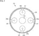
- Fig. 7 is a sectional view that schematically shows a configuration of the fluid sterilization device shown in Fig. 6 .
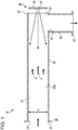
- Fig. 1 is a diagram that schematically shows a configuration of a fluid sterilization device 10 according to a first embodiment.
- the fluid sterilization device 10 comprises a straight pipe 20, an outflow pipe 30, and a light source 40.
- the light source 40 is disposed at an end part (a second end part 22) of the straight pipe 20 to emit ultraviolet light toward the inside of the straight pipe 20.
- the fluid sterilization device 10 is used to irradiate a fluid, such as water, flowing within the straight pipe 20 with ultraviolet light for sterilization treatment.
- the straight pipe 20 includes a first end part 21, the second end part 22, a first flange 26, and a window part 28.
- the straight pipe 20 extends in the longitudinal direction from the first end part 21 toward the second end part 22.
- the first end part 21 is provided with an inlet port 23 through which a fluid flows into the straight pipe 20 in the longitudinal direction of the straight pipe 20, and with the first flange 26 for connecting the inlet port 23 to another pipe or the like.
- the second end part 22 is provided with the window part 28 for transmitting ultraviolet light emitted by the light source 40.
- the window part 28 is constituted by a member having high ultraviolet light transmittance, such as quartz (SiO 2 ), sapphire (Al 2 O 3 ), and amorphous fluororesin.
- an outlet port 24 through which a fluid flows out in a direction intersecting or perpendicular to a longitudinal direction of the straight pipe 20.
- the outlet port 24 is provided on a side wall of the straight pipe 20 and, to the outlet port 24, the outflow pipe 30 is attached.
- One end of the outflow pipe 30 is attached to the outlet port 24, and the other end thereof is provided with a second flange 32. Accordingly, the straight pipe 20 and the outflow pipe 30 form a flow passage 12 of an L shape. A fluid flowing in through the first flange 26 will flow through the inlet port 23, straight pipe 20, outlet port 24, and outflow pipe 30 to flow out through the second flange 32.
- Each of the straight pipe 20 and the outflow pipe 30 is made of a metal material or resin material.
- An inner wall surface 20a of the straight pipe 20 is desirably made of a material having a high ultraviolet light reflectance, such as mirror-polished aluminum (Al) and polytetrafluoroethylene (PTFE), which is fully fluorinated resin.
- a material having a high ultraviolet light reflectance such as mirror-polished aluminum (Al) and polytetrafluoroethylene (PTFE), which is fully fluorinated resin.
- the value of the critical Reynolds number or lower may be the Reynolds number of 3000 or lower, preferably 2500 or lower, and more preferably 2320 or lower.
- the fluid flows in a laminar state toward the second end part 22.
- the flow velocity distribution is made so that a flow velocity v 1 of the fluid flowing near the central axis of the straight pipe 20 is relatively higher, and a flow velocity v 2 of the fluid flowing near the inner wall surface 20a of the straight pipe 20 is relatively lower.
- the velocity distribution of the fluid flowing through the flow passage 12 is expressed by an equation for a paraboloid of revolution.
- the light source 40 includes a light emitting element 42 and a substrate 44.
- the light emitting element 42 is an light emitting diode (LED) that emits ultraviolet light of which the center wavelength or peak wavelength falls within a range of about 200 nm to 350 nm.
- the light emitting element 42 may suitably emit ultraviolet light of which the wavelength falls within a range of about 260 nm to 270 nm, which has high sterilization efficiency.
- LED light emitting diode
- AlGaN aluminum gallium nitride
- the light emitting element 42 is an LED having a predetermined directional angle or light distribution angle and may be an LED having a wide light distribution angle of 120 degrees or greater (in total angular value), for example.
- As the light emitting element 42 there is an LED of a surface mount device (SMD) type having high output intensity.
- the light emitting element 42 is disposed on the central axis of the straight pipe 20 and mounted on the substrate 44 so as to face the window part 28.
- the substrate 44 is constituted by a member having high thermal conductivity, and copper (Cu) or aluminum (Al) may be used as a base material thereof, for example. Heat generated by the light emitting element 42 is dissipated through the substrate 44.
- Fig. 2 is a contour diagram that shows an ultraviolet intensity distribution within the flow passage 12. Since the light emitting element 42 emits ultraviolet light with a predetermined light distribution angle, the intensity distribution is made so that the ultraviolet intensity in an area near the center is higher than the ultraviolet intensity around the area. As a result, the intensity distribution of ultraviolet light within the straight pipe 20 is made so that, on a cross section of the flow passage 12 perpendicular to the longitudinal direction, the ultraviolet intensity near the central axis is higher, whereas the ultraviolet intensity near the inner wall surface 20a is lower.
- the fluid sterilization device 10 irradiates a fluid flowing within the straight pipe 20 with ultraviolet light so as to perform sterilization treatment on the fluid.
- the light source 40 emits ultraviolet light so that the intensity thereof near the center of the straight pipe 20 is higher, and the intensity thereof near the inner wall surface 20a of the straight pipe 20 is lower. Meanwhile, the fluid is made to flow through the flow passage 12 in a laminar state in which a flow velocity v 1 near the center is higher, and a flow velocity v 2 near the inner wall surface 20a is lower.
- the amount of ultraviolet light energy acting on the fluid flowing in a laminar state through the straight pipe 20 can be equalized, irrespective of the position in a radial direction of the flowing fluid. Accordingly, the entirety of the fluid flowing through the straight pipe 20 can be irradiated with ultraviolet light having a predetermined amount or more of energy, so that the sterilization effect on the entire fluid can be improved.
- the example of Fig. 3 shows a state where the flow velocity in a partial area near the inner wall surface 20a is the highest, and the flow velocity near the center shows a negative value; however, the velocity distribution of a fluid is not steady and occasionally changes with time.
- the survival rate of the Escherichia coli in the fluid that had flowed through the sterilization device was 0.53%.
- the flow velocity distribution basically shows that the flow velocity near the center is higher, and the flow velocity near the inner wall surface 20a is lower.
- the survival rate of the Escherichia coli in the fluid that had flowed through the sterilization device was 0.07%.
- the inlet port 23 and the light source 40 are disposed on the central axis of the straight pipe 20, a smooth flow of the fluid can be made in the direction toward ultraviolet light emitted by the light source 40. Since the inlet port 23 is disposed at a position opposite to the light source 40, the fluid reaches a laminar state with less turbulence while flowing through the straight pipe 20, and the fluid in the laminar state can be irradiated with strong ultraviolet light.
- the situation can be prevented in which inconsistency occurs in the amount of ultraviolet light energy acting on the fluid because part of the fluid flows through an area of low ultraviolet intensity at a high velocity or because part of the fluid swirls and remains in an area of high ultraviolet intensity, for example, so that the influence of sterilization effect reduced by the situation can be curbed.
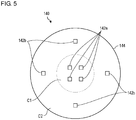
- Fig. 5 is a front view that schematically shows a configuration of a light source 140 according to a modification.
- the light source 140 includes multiple light emitting elements 142a and 142b, and a substrate 144.
- the light source 140 includes multiple first light emitting elements 142a densely disposed in a central area C1 of the substrate 144, and multiple second light emitting elements 142b disposed to dot a peripheral area C2 of the substrate 144.
- Each of the first light emitting elements 142a and the second light emitting elements 142b is configured similarly to the light emitting element 42 described previously.
- the light source 140 since the first light emitting elements 142a are densely disposed in the central area C1, ultraviolet light having relatively high intensity is outputted from the central area C1. Meanwhile, since the second light emitting elements 142b are disposed to dot the peripheral area C2, ultraviolet light having relatively low intensity is outputted from the peripheral area C2. Accordingly, even when the diameter d of the straight pipe 20 is enlarged to increase the flow rate, by applying the light source 140 of the present modification to the fluid sterilization device 10 described previously, a fluid can be irradiated with ultraviolet light having an intensity distribution in which the ultraviolet intensity is higher near the center and lower near the inner wall surface 20a.
- FIG. 6 and 7 is a sectional view that schematically shows a configuration of a fluid sterilization device 210 according to a second embodiment, and Fig. 7 corresponds to a sectional view taken along line A-A in Fig. 6 .
- the fluid sterilization device 210 comprises a straight pipe 220, an inflow pipe 231, an outflow pipe 232, multiple first light sources 240a, and multiple second light sources 240b.
- the fluid sterilization device 210 is different from the fluid sterilization device in the aforementioned first embodiment in that the inflow pipe 231 and the outflow pipe 232 are disposed on the central axis of the straight pipe 220, so that a flow passage 212 of a linear shape, instead of an L shape, is formed.
- the present embodiment will be described mainly for the differences from the first embodiment.
- the straight pipe 220 extends from a first end part 221 toward a second end part 222.
- the first end part 221 is provided with a first end surface 221a perpendicular to a longitudinal direction of the straight pipe 220, and with an inlet port 223 positioned near the center of the first end surface 221a.
- the first end surface 221a is provided with multiple first window parts 227 for transmitting ultraviolet light emitted by the first light sources 240a.
- the inflow pipe 231 extending in a longitudinal direction of the straight pipe 220 is attached. Through the inflow pipe 231, a fluid flows into the straight pipe 220 in the longitudinal direction of the straight pipe 220, thereby reducing the generation of turbulence in the flow within the flow passage 212.
- the second end part 222 is configured similarly to the first end part 221.
- the second end part 222 is provided with a second end surface 222a perpendicular to a longitudinal direction of the straight pipe 220, and with an outlet port 224 positioned near the center of the second end surface 222a.
- the second end surface 222a is provided with multiple second window parts 228 for transmitting ultraviolet light emitted by the second light sources 240b.
- the outflow pipe 232 extending in a longitudinal direction of the straight pipe 220 is attached. Through the outflow pipe 232, a fluid flows out of the straight pipe 220 in the longitudinal direction of the straight pipe 220, thereby reducing the generation of turbulence in the flow within the flow passage 212.
- the first light sources 240a include multiple first light emitting elements 242a and multiple first substrates 244a.
- the multiple first light emitting elements 242a are disposed on all sides so as to surround the inlet port 223 and mounted respectively on the first substrates 244a, as shown in Fig. 7 .
- Each of the multiple first light emitting elements 242a emits ultraviolet light in the longitudinal direction of the straight pipe 220 toward the inside of the straight pipe 220, through the corresponding first window part 227.
- Fig. 7 shows the case where the first light emitting elements 242a are provided at four positions, the number of positions at which the first light emitting elements 242a are provided may be three or less, or may be five or more. It is suitable that the multiple first light emitting elements 242a are evenly spaced so as to emit ultraviolet light to the entire fluid flowing within the flow passage 212. Since the multiple first light emitting elements 242a are evenly spaced so as to surround the inlet port 223, the first light sources 240a emit ultraviolet light having an intensity distribution in which the ultraviolet intensity is higher near the center of the straight pipe 220 and lower near an inner wall surface 220a of the straight pipe 220.
- the second light sources 240b include multiple second light emitting elements 242b and multiple second substrates 244b and are configured similarly to the first light sources 240a.
- the multiple second light emitting elements 242b are disposed on all sides so as to surround the outlet port 224 and mounted respectively on the second substrates 244b.
- Each of the multiple second light emitting elements 242b emits ultraviolet light in the longitudinal direction of the straight pipe 220 toward the inside of the straight pipe 220, through the corresponding second window part 228.
- the second light sources 240b emit ultraviolet light having an intensity distribution in which the ultraviolet intensity is higher near the center of the straight pipe 220 and lower near the inner wall surface 220a of the straight pipe 220.
- the inner diameter of the straight pipe 220 and the average flow velocity of a fluid flowing through the flow passage 112 are adjusted so that the fluid flows through the flow passage 212 in a laminar state. Accordingly, the flow velocity distribution is made so that the flow velocity of the fluid flowing near the central axis of the straight pipe 220 is relatively higher, and the flow velocity of the fluid flowing near the inner wall surface 220a of the straight pipe 220 is relatively lower.
- the fluid with such a velocity distribution is irradiated with ultraviolet light having an intensity distribution in which the ultraviolet intensity is higher near the center of the straight pipe 220 and lower near the inner wall surface 220a, emitted by the first light sources 240a and the second light sources 240b.
- a fluid in a laminar state is irradiated with ultraviolet light of which the intensity distribution corresponds to the flow velocity distribution of a fluid in a laminar state, so that the sterilization effect on the fluid can be improved.
- the inlet port 223 and the outlet port 224 are disposed on the central axis of the straight pipe 220, generation of turbulence or a swirl in the fluid flowing through the flow passage 212 can be reduced. Further, since the light sources 240a and 240b are provided respectively at the inlet port 223 and the outlet port 224, the amount of ultraviolet light energy acting on the fluid can be increased compared to the case in which ultraviolet light is emitted from only one side, so that the sterilization effect on the fluid can be improved.
- the light sources may be provided at only one of the inlet port 223 and the outlet port 224.
- the light sources 240a and 240b may be provided inside the straight pipe 220.
- the light sources 240a and 240b are respectively mounted on end surfaces 221a and 222b of the straight pipe 220, and cover members or the likes, which transmit ultraviolet light, are provided so that the light sources are not directly in contact with the fluid flowing within the flow passage 212.
- the fluid sterilization devices 10 are described as devices for performing sterilization treatment by irradiating a fluid with ultraviolet light.
- the fluid sterilization devices may be used for purification treatment for decomposing an organic substance included in a fluid by irradiation of ultraviolet light.
- a straightening plate may be provided, midway along the flow passage constituted by a straight pipe, at the inlet port, or on the upstream side of the inlet port described above.
- the straightening plate may have a function to straighten the flow of a fluid flowing through the flow passage so as to make the flow a laminar flow. With the straightening plate, a laminar state with less turbulence can be formed, so that the sterilization effect can be improved.
- the light sources may have an adjustment mechanism for adjusting the intensity distribution of ultraviolet light emitted by the light emitting elements.
- the adjustment mechanism may include a transmitting optical element, such as a lens, and a reflecting optical element, such as a concave mirror.
- the adjustment mechanism may adjust the intensity distribution of ultraviolet light emitted by the light emitting elements so as to make the intensity distribution of ultraviolet light outputted by the light sources correspond to the velocity distribution of a fluid in a laminar state.
- a fluid can be irradiated with ultraviolet light of which the intensity distribution is suitable to the state of flow of the fluid, so that the sterilization effect can be further improved.
- the present invention enables improvement in irradiation efficiency of ultraviolet light for a fluid flowing within a flow passage, thereby also improving the sterilization capability.
Landscapes
- Health & Medical Sciences (AREA)
- Life Sciences & Earth Sciences (AREA)
- Epidemiology (AREA)
- Animal Behavior & Ethology (AREA)
- General Health & Medical Sciences (AREA)
- Public Health (AREA)
- Veterinary Medicine (AREA)
- Hydrology & Water Resources (AREA)
- Toxicology (AREA)
- Engineering & Computer Science (AREA)
- Environmental & Geological Engineering (AREA)
- Water Supply & Treatment (AREA)
- Chemical & Material Sciences (AREA)
- Organic Chemistry (AREA)
- Physical Water Treatments (AREA)
- Apparatus For Disinfection Or Sterilisation (AREA)
Abstract
Description
- The present invention relates to a fluid sterilization device and a fluid sterilization method and, more particularly, to a technology of sterilizing a fluid by irradiating the fluid with ultraviolet light.
- It is known that ultraviolet light has sterilization capability. Devices that radiate ultraviolet light are used for sterilization in medical and food processing fronts. Devices that sterilize a fluid such as water continuously by irradiating the fluid with ultraviolet light are also used. One example is a device in which an ultraviolet LED is provided on the inner wall at a pipe end of a flow passage formed by a straight metal pipe (see Patent Document 1, for example).
- [Patent Document 1] Japanese Unexamined Patent Application Publication No.
2011-16074 - In order to irradiate a fluid with ultraviolet light with high efficiency, it is desirable to control the state of flow of the fluid in the flow passage appropriately and to radiate ultraviolet light in a mode suitable to the state of flow.
- The present invention has been made in view of such a problem, and an illustrative purpose thereof is to provide a fluid sterilization device with improved irradiation efficiency of ultraviolet light for a fluid flowing within a flow passage.
- A fluid sterilization device of one embodiment of the present invention includes: a straight pipe that constitutes a flow passage extending in a longitudinal direction; and a light source that emits ultraviolet light in the longitudinal direction toward a fluid flowing in a laminar state within the flow passage. The light source includes a light emitting element for emitting ultraviolet light and emits ultraviolet light so as to provide an intensity distribution on a cross section of the flow passage perpendicular to a longitudinal direction, in which the ultraviolet intensity in an area near the center is higher than the ultraviolet intensity around the area.
- According to this embodiment, since a fluid flowing in a laminar state is irradiated with ultraviolet light, the sterilization effect can be improved compared to the case where a fluid in a turbulent state is irradiated with ultraviolet light. Based on the inventors' findings, it is found that, when sterilization treatment is performed by irradiating a fluid within a flow passage of a straight pipe with ultraviolet light, in the case of a laminar state, about seven times the sterilization effect of the case of a turbulent state can be obtained. Also, a fluid in a laminar state has a velocity distribution in which the flow velocity near the center is higher, and the flow velocity near the inner wall of the pipe is lower; accordingly, by increasing the ultraviolet intensity near the center according to the velocity distribution, the fluid flowing within the flow passage can be effectively irradiated with ultraviolet light, so that the sterilization effect can be improved.
- The straight pipe may include a first end part provided with an inlet port through which a fluid flows into the straight pipe in the longitudinal direction, and also include a second end part located opposite to the first end part. The light source may be disposed at the second end part.
- The light source and the inlet port may be disposed on the central axis of the straight pipe.
- The straight pipe may include an outlet port provided on the second end part, through which a fluid flows out in a direction intersecting the longitudinal direction.
- The straight pipe may include an outlet port provided on the second end part, through which a fluid flows out in the longitudinal direction. The light source may include a plurality of light emitting elements disposed so as to surround the outlet port. The plurality of light emitting elements may emit ultraviolet light in the longitudinal direction toward a fluid flowing within the flow passage.
- The fluid sterilization device may further include a straightening plate that makes a flow of a fluid within the flow passage a laminar flow.
- Another embodiment of the present invention relates to a fluid sterilization method. In the fluid sterilization method, a flow of a fluid in a laminar state is made within a straight pipe that constitutes a flow passage extending in a longitudinal direction, and ultraviolet light is emitted in the longitudinal direction toward a fluid flowing in a laminar state within the flow passage so as to provide an intensity distribution on a cross section of the flow passage perpendicular to the longitudinal direction, in which the ultraviolet intensity in an area near the center is higher than the ultraviolet intensity around the area.
- According to this embodiment, since a fluid flowing in a laminar state is irradiated with ultraviolet light, the sterilization effect can be improved compared to the case where a fluid in a turbulent state is irradiated with ultraviolet light. Also, a fluid in a laminar state has a velocity distribution in which the flow velocity near the center is higher, and the flow velocity near the inner wall of the pipe is lower; accordingly, by increasing the ultraviolet intensity near the center according to the velocity distribution, the fluid flowing within the flow passage can be effectively irradiated with ultraviolet light, so that the sterilization effect can be improved.
- The present invention enables improvement in irradiation efficiency of ultraviolet light for a fluid flowing within a flow passage, thereby also improving the sterilization capability.
-
-
Fig. 1 is a sectional view that schematically shows a configuration of a fluid sterilization device according to a first embodiment; -
Fig. 2 is a contour diagram that shows an ultraviolet intensity distribution within a flow passage; -
Fig. 3 is a contour diagram that shows a velocity distribution of a fluid in a turbulent state; -
Fig. 4 is a contour diagram that shows a velocity distribution of a fluid in a laminar state; -
Fig. 5 is a front view that schematically shows a configuration of a light source according to a modification; -
Fig. 6 is a sectional view that schematically shows a configuration of a fluid sterilization device according to a -
Fig. 7 is a sectional view that schematically shows a configuration of the fluid sterilization device shown inFig. 6 . - In the following, a mode for carrying out the present invention will be described in detail with reference to the drawings. Like reference characters denote like elements in the description, and the same description will be omitted as appropriate.
-
Fig. 1 is a diagram that schematically shows a configuration of a fluid sterilization device 10 according to a first embodiment. The fluid sterilization device 10 comprises a straight pipe 20, anoutflow pipe 30, and a light source 40. The light source 40 is disposed at an end part (a second end part 22) of the straight pipe 20 to emit ultraviolet light toward the inside of the straight pipe 20. The fluid sterilization device 10 is used to irradiate a fluid, such as water, flowing within the straight pipe 20 with ultraviolet light for sterilization treatment. - The straight pipe 20 includes a
first end part 21, thesecond end part 22, afirst flange 26, and awindow part 28. The straight pipe 20 extends in the longitudinal direction from thefirst end part 21 toward thesecond end part 22. Thefirst end part 21 is provided with aninlet port 23 through which a fluid flows into the straight pipe 20 in the longitudinal direction of the straight pipe 20, and with thefirst flange 26 for connecting theinlet port 23 to another pipe or the like. Thesecond end part 22 is provided with thewindow part 28 for transmitting ultraviolet light emitted by the light source 40. Thewindow part 28 is constituted by a member having high ultraviolet light transmittance, such as quartz (SiO2), sapphire (Al2O3), and amorphous fluororesin. - On the
second end part 22 is provided anoutlet port 24 through which a fluid flows out in a direction intersecting or perpendicular to a longitudinal direction of the straight pipe 20. Theoutlet port 24 is provided on a side wall of the straight pipe 20 and, to theoutlet port 24, theoutflow pipe 30 is attached. One end of theoutflow pipe 30 is attached to theoutlet port 24, and the other end thereof is provided with asecond flange 32. Accordingly, the straight pipe 20 and theoutflow pipe 30 form a flow passage 12 of an L shape. A fluid flowing in through thefirst flange 26 will flow through theinlet port 23, straight pipe 20,outlet port 24, andoutflow pipe 30 to flow out through thesecond flange 32. - Each of the straight pipe 20 and the
outflow pipe 30 is made of a metal material or resin material. Aninner wall surface 20a of the straight pipe 20 is desirably made of a material having a high ultraviolet light reflectance, such as mirror-polished aluminum (Al) and polytetrafluoroethylene (PTFE), which is fully fluorinated resin. By using such a material to configure theinner wall surface 20a of the straight pipe 20, ultraviolet light emitted by the light source 40 is reflected by theinner wall surface 20a, so as to be transmitted in the longitudinal direction of the straight pipe 20. Since PTFE is a chemically stable material having a high ultraviolet light reflectance, it is suitable as a material of the straight pipe 20 that constitutes a flow passage of the fluid sterilization device. - An inner diameter d of the straight pipe 20 and an average flow velocity v of a fluid flowing through the flow passage 12 are adjusted so that the fluid flows through the flow passage 12 in a laminar state. More specifically, the inner diameter d and the average flow velocity v are adjusted so that the Reynolds number Re in the flow passage 12 becomes the critical Reynolds number in a laminar state or lower, based on the equation of Re=v·d/ν (ν: the coefficient of kinematic viscosity of the fluid). The value of the critical Reynolds number or lower may be the Reynolds number of 3000 or lower, preferably 2500 or lower, and more preferably 2320 or lower. By allowing a fluid to flow through the
inlet port 23 into the flow passage 12 in the longitudinal direction, the fluid flows in a laminar state toward thesecond end part 22. When a fluid is flowing in a laminar state, the flow velocity distribution is made so that a flow velocity v1 of the fluid flowing near the central axis of the straight pipe 20 is relatively higher, and a flow velocity v2 of the fluid flowing near theinner wall surface 20a of the straight pipe 20 is relatively lower. In an ideal laminar state, the velocity distribution of the fluid flowing through the flow passage 12 is expressed by an equation for a paraboloid of revolution. - The light source 40 includes a light emitting element 42 and a substrate 44. The light emitting element 42 is an light emitting diode (LED) that emits ultraviolet light of which the center wavelength or peak wavelength falls within a range of about 200 nm to 350 nm. The light emitting element 42 may suitably emit ultraviolet light of which the wavelength falls within a range of about 260 nm to 270 nm, which has high sterilization efficiency. As such an ultraviolet LED, one using aluminum gallium nitride (AlGaN) is known, for example.
- The light emitting element 42 is an LED having a predetermined directional angle or light distribution angle and may be an LED having a wide light distribution angle of 120 degrees or greater (in total angular value), for example. As the light emitting element 42, there is an LED of a surface mount device (SMD) type having high output intensity. The light emitting element 42 is disposed on the central axis of the straight pipe 20 and mounted on the substrate 44 so as to face the
window part 28. The substrate 44 is constituted by a member having high thermal conductivity, and copper (Cu) or aluminum (Al) may be used as a base material thereof, for example. Heat generated by the light emitting element 42 is dissipated through the substrate 44. -
Fig. 2 is a contour diagram that shows an ultraviolet intensity distribution within the flow passage 12. Since the light emitting element 42 emits ultraviolet light with a predetermined light distribution angle, the intensity distribution is made so that the ultraviolet intensity in an area near the center is higher than the ultraviolet intensity around the area. As a result, the intensity distribution of ultraviolet light within the straight pipe 20 is made so that, on a cross section of the flow passage 12 perpendicular to the longitudinal direction, the ultraviolet intensity near the central axis is higher, whereas the ultraviolet intensity near theinner wall surface 20a is lower. - With the configuration set forth above, the fluid sterilization device 10 irradiates a fluid flowing within the straight pipe 20 with ultraviolet light so as to perform sterilization treatment on the fluid. The light source 40 emits ultraviolet light so that the intensity thereof near the center of the straight pipe 20 is higher, and the intensity thereof near the
inner wall surface 20a of the straight pipe 20 is lower. Meanwhile, the fluid is made to flow through the flow passage 12 in a laminar state in which a flow velocity v1 near the center is higher, and a flow velocity v2 near theinner wall surface 20a is lower. As a result, the amount of ultraviolet light energy acting on the fluid flowing in a laminar state through the straight pipe 20 can be equalized, irrespective of the position in a radial direction of the flowing fluid. Accordingly, the entirety of the fluid flowing through the straight pipe 20 can be irradiated with ultraviolet light having a predetermined amount or more of energy, so that the sterilization effect on the entire fluid can be improved. - There will now be described an effect of the fluid sterilization device 10 with reference to a comparative example.
Fig. 3 is a contour diagram that shows a velocity distribution of a fluid in a turbulent state when the fluid flows through the straight pipe 20 under the condition of the Reynolds number Re = 4961. The example ofFig. 3 shows a state where the flow velocity in a partial area near theinner wall surface 20a is the highest, and the flow velocity near the center shows a negative value; however, the velocity distribution of a fluid is not steady and occasionally changes with time. Under the condition of such a turbulent state, when bacterial liquid containing Escherichia coli was used as the fluid, the survival rate of the Escherichia coli in the fluid that had flowed through the sterilization device was 0.53%. -
Fig. 4 is a contour diagram that shows a velocity distribution of a fluid in a laminar state when the fluid flows through the straight pipe 20 under the condition of the Reynolds number Re = 2279. In the example ofFig. 4 , although the area in which the flow velocity is highest is shifted to an upper right area, the flow velocity distribution basically shows that the flow velocity near the center is higher, and the flow velocity near theinner wall surface 20a is lower. Under the condition of such a laminar state, when bacterial liquid containing Escherichia coli was used, the survival rate of the Escherichia coli in the fluid that had flowed through the sterilization device was 0.07%. From these results, it is found that, in a laminar state, about seven times the sterilization effect of the case of a turbulent state can be obtained. Thus, in the present embodiment, since a fluid in a laminar state can be irradiated with ultraviolet light of which the intensity distribution corresponds to the flow velocity distribution of a fluid in a laminar state, the sterilization effect on the fluid can be improved. - Also, in the present embodiment, since the
inlet port 23 and the light source 40 are disposed on the central axis of the straight pipe 20, a smooth flow of the fluid can be made in the direction toward ultraviolet light emitted by the light source 40. Since theinlet port 23 is disposed at a position opposite to the light source 40, the fluid reaches a laminar state with less turbulence while flowing through the straight pipe 20, and the fluid in the laminar state can be irradiated with strong ultraviolet light. Accordingly, the situation can be prevented in which inconsistency occurs in the amount of ultraviolet light energy acting on the fluid because part of the fluid flows through an area of low ultraviolet intensity at a high velocity or because part of the fluid swirls and remains in an area of high ultraviolet intensity, for example, so that the influence of sterilization effect reduced by the situation can be curbed. -
Fig. 5 is a front view that schematically shows a configuration of alight source 140 according to a modification. Thelight source 140 includes multiplelight emitting elements substrate 144. Thelight source 140 includes multiple firstlight emitting elements 142a densely disposed in a central area C1 of thesubstrate 144, and multiple secondlight emitting elements 142b disposed to dot a peripheral area C2 of thesubstrate 144. Each of the firstlight emitting elements 142a and the secondlight emitting elements 142b is configured similarly to the light emitting element 42 described previously. - In the
light source 140, since the firstlight emitting elements 142a are densely disposed in the central area C1, ultraviolet light having relatively high intensity is outputted from the central area C1. Meanwhile, since the secondlight emitting elements 142b are disposed to dot the peripheral area C2, ultraviolet light having relatively low intensity is outputted from the peripheral area C2. Accordingly, even when the diameter d of the straight pipe 20 is enlarged to increase the flow rate, by applying thelight source 140 of the present modification to the fluid sterilization device 10 described previously, a fluid can be irradiated with ultraviolet light having an intensity distribution in which the ultraviolet intensity is higher near the center and lower near theinner wall surface 20a. - Each of
Figs. 6 and7 is a sectional view that schematically shows a configuration of afluid sterilization device 210 according to a second embodiment, andFig. 7 corresponds to a sectional view taken along line A-A inFig. 6 . Thefluid sterilization device 210 comprises astraight pipe 220, aninflow pipe 231, anoutflow pipe 232, multiplefirst light sources 240a, and multiple secondlight sources 240b. Thefluid sterilization device 210 is different from the fluid sterilization device in the aforementioned first embodiment in that theinflow pipe 231 and theoutflow pipe 232 are disposed on the central axis of thestraight pipe 220, so that aflow passage 212 of a linear shape, instead of an L shape, is formed. In the following, the present embodiment will be described mainly for the differences from the first embodiment. - The
straight pipe 220 extends from afirst end part 221 toward asecond end part 222. Thefirst end part 221 is provided with afirst end surface 221a perpendicular to a longitudinal direction of thestraight pipe 220, and with aninlet port 223 positioned near the center of thefirst end surface 221a. Also, thefirst end surface 221a is provided with multiplefirst window parts 227 for transmitting ultraviolet light emitted by thefirst light sources 240a. To theinlet port 223, theinflow pipe 231 extending in a longitudinal direction of thestraight pipe 220 is attached. Through theinflow pipe 231, a fluid flows into thestraight pipe 220 in the longitudinal direction of thestraight pipe 220, thereby reducing the generation of turbulence in the flow within theflow passage 212. - The
second end part 222 is configured similarly to thefirst end part 221. Thesecond end part 222 is provided with asecond end surface 222a perpendicular to a longitudinal direction of thestraight pipe 220, and with anoutlet port 224 positioned near the center of thesecond end surface 222a. Also, thesecond end surface 222a is provided with multiplesecond window parts 228 for transmitting ultraviolet light emitted by the secondlight sources 240b. To theoutlet port 224, theoutflow pipe 232 extending in a longitudinal direction of thestraight pipe 220 is attached. Through theoutflow pipe 232, a fluid flows out of thestraight pipe 220 in the longitudinal direction of thestraight pipe 220, thereby reducing the generation of turbulence in the flow within theflow passage 212. - The
first light sources 240a include multiple firstlight emitting elements 242a and multiplefirst substrates 244a. The multiple firstlight emitting elements 242a are disposed on all sides so as to surround theinlet port 223 and mounted respectively on thefirst substrates 244a, as shown inFig. 7 . Each of the multiple firstlight emitting elements 242a emits ultraviolet light in the longitudinal direction of thestraight pipe 220 toward the inside of thestraight pipe 220, through the correspondingfirst window part 227. - Although the example of
Fig. 7 shows the case where the firstlight emitting elements 242a are provided at four positions, the number of positions at which the firstlight emitting elements 242a are provided may be three or less, or may be five or more. It is suitable that the multiple firstlight emitting elements 242a are evenly spaced so as to emit ultraviolet light to the entire fluid flowing within theflow passage 212. Since the multiple firstlight emitting elements 242a are evenly spaced so as to surround theinlet port 223, thefirst light sources 240a emit ultraviolet light having an intensity distribution in which the ultraviolet intensity is higher near the center of thestraight pipe 220 and lower near aninner wall surface 220a of thestraight pipe 220. - The second
light sources 240b include multiple secondlight emitting elements 242b and multiplesecond substrates 244b and are configured similarly to thefirst light sources 240a. The multiple secondlight emitting elements 242b are disposed on all sides so as to surround theoutlet port 224 and mounted respectively on thesecond substrates 244b. Each of the multiple secondlight emitting elements 242b emits ultraviolet light in the longitudinal direction of thestraight pipe 220 toward the inside of thestraight pipe 220, through the correspondingsecond window part 228. As with thefirst light sources 240a, the secondlight sources 240b emit ultraviolet light having an intensity distribution in which the ultraviolet intensity is higher near the center of thestraight pipe 220 and lower near theinner wall surface 220a of thestraight pipe 220. - The inner diameter of the
straight pipe 220 and the average flow velocity of a fluid flowing through the flow passage 112 are adjusted so that the fluid flows through theflow passage 212 in a laminar state. Accordingly, the flow velocity distribution is made so that the flow velocity of the fluid flowing near the central axis of thestraight pipe 220 is relatively higher, and the flow velocity of the fluid flowing near theinner wall surface 220a of thestraight pipe 220 is relatively lower. The fluid with such a velocity distribution is irradiated with ultraviolet light having an intensity distribution in which the ultraviolet intensity is higher near the center of thestraight pipe 220 and lower near theinner wall surface 220a, emitted by thefirst light sources 240a and the secondlight sources 240b. Therefore, also in the present embodiment, a fluid in a laminar state is irradiated with ultraviolet light of which the intensity distribution corresponds to the flow velocity distribution of a fluid in a laminar state, so that the sterilization effect on the fluid can be improved. - Also, in the present embodiment, since the
inlet port 223 and theoutlet port 224 are disposed on the central axis of thestraight pipe 220, generation of turbulence or a swirl in the fluid flowing through theflow passage 212 can be reduced. Further, since thelight sources inlet port 223 and theoutlet port 224, the amount of ultraviolet light energy acting on the fluid can be increased compared to the case in which ultraviolet light is emitted from only one side, so that the sterilization effect on the fluid can be improved. - In a modification, the light sources may be provided at only one of the
inlet port 223 and theoutlet port 224. Also, thelight sources straight pipe 220. When thelight sources straight pipe 220, thelight sources end surfaces 221a and 222b of thestraight pipe 220, and cover members or the likes, which transmit ultraviolet light, are provided so that the light sources are not directly in contact with the fluid flowing within theflow passage 212. - The present invention has been described with reference to embodiments. It should be understood by those skilled in the art that the invention is not limited to the above-described embodiments and that various modifications could be developed on the basis of various design modifications and such modifications also fall within the scope of the present invention.
- The fluid sterilization devices 10 according to the aforementioned embodiments are described as devices for performing sterilization treatment by irradiating a fluid with ultraviolet light. In a modification, the fluid sterilization devices may be used for purification treatment for decomposing an organic substance included in a fluid by irradiation of ultraviolet light.
- In a modification, a straightening plate may be provided, midway along the flow passage constituted by a straight pipe, at the inlet port, or on the upstream side of the inlet port described above. The straightening plate may have a function to straighten the flow of a fluid flowing through the flow passage so as to make the flow a laminar flow. With the straightening plate, a laminar state with less turbulence can be formed, so that the sterilization effect can be improved.
- In a modification, the light sources may have an adjustment mechanism for adjusting the intensity distribution of ultraviolet light emitted by the light emitting elements. The adjustment mechanism may include a transmitting optical element, such as a lens, and a reflecting optical element, such as a concave mirror. The adjustment mechanism may adjust the intensity distribution of ultraviolet light emitted by the light emitting elements so as to make the intensity distribution of ultraviolet light outputted by the light sources correspond to the velocity distribution of a fluid in a laminar state. With such an adjustment mechanism, a fluid can be irradiated with ultraviolet light of which the intensity distribution is suitable to the state of flow of the fluid, so that the sterilization effect can be further improved.
-
- 10
- fluid sterilization device
- 12
- flow passage
- 20
- straight pipe
- 21
- first end part
- 22
- second end part
- 23
- inlet port
- 24
- outlet port
- 40
- light source
- 42
- light emitting element
- 140
- light source
- 210
- fluid sterilization device
- 212
- flow passage
- 220
- straight pipe
- 221
- first end part
- 222
- second end part
- 223
- inlet port
- 224
- outlet port
- 240a
- first light sources
- 240b
- second light sources
- The present invention enables improvement in irradiation efficiency of ultraviolet light for a fluid flowing within a flow passage, thereby also improving the sterilization capability.
Claims (7)
- A fluid sterilization device, comprising:a straight pipe that constitutes a flow passage extending in a longitudinal direction; anda light source that emits ultraviolet light in the longitudinal direction toward a fluid flowing in a laminar state within the flow passage, whereinthe light source includes a light emitting element for emitting ultraviolet light and emits ultraviolet light so as to provide an intensity distribution on a cross section of the flow passage perpendicular to the longitudinal direction, in which the ultraviolet intensity in an area near the center is higher than the ultraviolet intensity around the area.
- The fluid sterilization device of claim 1, wherein:the straight pipe includes a first end part provided with an inlet port through which a fluid flows into the straight pipe in the longitudinal direction, and also includes a second end part located opposite to the first end part; andthe light source is disposed at the second end part.
- The fluid sterilization device of claim 2, wherein the light source and the inlet port are disposed on the central axis of the straight pipe.
- The fluid sterilization device of claim 2 or 3, wherein the straight pipe includes an outlet port provided on the second end part, through which a fluid flows out in a direction intersecting the longitudinal direction.
- The fluid sterilization device of claim 2, wherein:the straight pipe includes an outlet port provided on the second end part, through which a fluid flows out in the longitudinal direction;the light source includes a plurality of light emitting elements disposed so as to surround the outlet port; andthe plurality of light emitting elements emit ultraviolet light in the longitudinal direction toward a fluid flowing within the flow passage.
- The fluid sterilization device of any one of claims 1 through 5, further comprising a straightening plate that makes a flow of a fluid within the flow passage a laminar flow.
- A fluid sterilization method, in which a flow of a fluid in a laminar state is made within a straight pipe that constitutes a flow passage extending in a longitudinal direction, and ultraviolet light is emitted in the longitudinal direction toward a fluid flowing in a laminar state within the flow passage so as to provide an intensity distribution on a cross section of the flow passage perpendicular to the longitudinal direction, in which the ultraviolet intensity in an area near the center is higher than the ultraviolet intensity around the area.
Applications Claiming Priority (2)
| Application Number | Priority Date | Filing Date | Title |
|---|---|---|---|
| JP2015202206A JP2017074114A (en) | 2015-10-13 | 2015-10-13 | Fluid sterilizer and fluid sterilization method |
| PCT/JP2016/076422 WO2017064950A1 (en) | 2015-10-13 | 2016-09-08 | Fluid sterilization device and fluid sterilization method |
Publications (2)
| Publication Number | Publication Date |
|---|---|
| EP3363468A1 true EP3363468A1 (en) | 2018-08-22 |
| EP3363468A4 EP3363468A4 (en) | 2019-07-24 |
Family
ID=58518116
Family Applications (1)
| Application Number | Title | Priority Date | Filing Date |
|---|---|---|---|
| EP16855204.0A Withdrawn EP3363468A4 (en) | 2015-10-13 | 2016-09-08 | FLUID STERILIZATION DEVICE AND FLUID STERILIZATION METHOD |
Country Status (7)
| Country | Link |
|---|---|
| US (1) | US20180228928A1 (en) |
| EP (1) | EP3363468A4 (en) |
| JP (1) | JP2017074114A (en) |
| KR (1) | KR20180059859A (en) |
| CN (1) | CN108136060A (en) |
| TW (1) | TWI626958B (en) |
| WO (1) | WO2017064950A1 (en) |
Families Citing this family (16)
| Publication number | Priority date | Publication date | Assignee | Title |
|---|---|---|---|---|
| JP6559577B2 (en) * | 2016-01-06 | 2019-08-14 | 日機装株式会社 | Fluid sterilization apparatus and fluid sterilization method |
| KR101918383B1 (en) * | 2017-01-18 | 2019-01-29 | 엘지전자 주식회사 | water purifier |
| US11312642B2 (en) | 2017-03-31 | 2022-04-26 | Industrial Technology Research Institute | Fluid sterilizing device |
| JP7035337B2 (en) * | 2017-05-22 | 2022-03-15 | 三菱電機株式会社 | Sterilizer and water heater |
| JP6863135B2 (en) * | 2017-06-29 | 2021-04-21 | 東芝ライテック株式会社 | Fluid sterilizer |
| JP7011931B2 (en) * | 2017-12-07 | 2022-02-10 | スタンレー電気株式会社 | Fluid sterilizer |
| JP6826141B2 (en) * | 2018-04-20 | 2021-02-03 | 旭化成株式会社 | Ultraviolet irradiation device |
| EP3578207B1 (en) | 2018-04-20 | 2024-06-19 | Asahi Kasei Kabushiki Kaisha | Ultraviolet light irradiation device |
| JP2020009858A (en) * | 2018-07-05 | 2020-01-16 | 株式会社エンプラス | Light-emitting device and sterilizer |
| JP7186383B2 (en) * | 2018-10-31 | 2022-12-09 | パナソニックIpマネジメント株式会社 | water treatment system |
| JP7262985B2 (en) * | 2018-12-04 | 2023-04-24 | スタンレー電気株式会社 | Light source module device, Fluid sterilization device |
| JP7182447B2 (en) * | 2018-12-12 | 2022-12-02 | スタンレー電気株式会社 | Fluid sterilizer and driving method |
| GB201900016D0 (en) | 2019-01-02 | 2019-02-13 | Dyson Technology Ltd | Air treatment apparatus |
| US11365134B2 (en) | 2019-07-31 | 2022-06-21 | Access Business Group International Llc | Water treatment system |
| US12161768B2 (en) | 2019-07-31 | 2024-12-10 | Asahi Kasei Kabushiki Kaisha | Ultraviolet irradiation apparatus and ultraviolet irradiation method |
| CN111617302A (en) * | 2020-03-20 | 2020-09-04 | 珠海码硕科技有限公司 | A light sterilization device |
Family Cites Families (17)
| Publication number | Priority date | Publication date | Assignee | Title |
|---|---|---|---|---|
| JPH077967Y2 (en) * | 1990-09-21 | 1995-03-01 | 中野 浩二 | UV irradiation device |
| US6524447B1 (en) * | 1999-11-22 | 2003-02-25 | Titan Technologies | Apparatus and method for photocatalytic purification and disinfection of water and ultrapure water |
| US6902653B2 (en) * | 1999-11-22 | 2005-06-07 | Titan Technologies | Apparatus and method for photocatalytic purification and disinfection of fluids |
| CN2699886Y (en) * | 2004-03-04 | 2005-05-18 | 中国农业大学 | Turbulent flow type ultraviolet sterilizing and disinfecting device |
| US7520978B2 (en) * | 2005-06-17 | 2009-04-21 | Philips Lumileds Lighting Co., Llc | Fluid purification system with ultra violet light emitters |
| AU2006288709B2 (en) * | 2005-09-06 | 2011-10-27 | Atlantium Technologies Ltd. | Method, device and system of illumination-based disinfection |
| JP4690872B2 (en) * | 2005-11-30 | 2011-06-01 | 株式会社東芝 | UV irradiation water treatment equipment |
| US20090289015A1 (en) * | 2008-05-21 | 2009-11-26 | Uri Levy | Back-surface mirrors for ultraviolet liquid disinfection systems |
| CA2676695C (en) * | 2007-02-23 | 2016-11-08 | Intelligent Hospital Systems Ltd. | Ultraviolet sanitization in pharmacy environments |
| JP5374697B2 (en) | 2009-07-09 | 2013-12-25 | ユーヴィックス株式会社 | UV sterilization water purifier and UV LED unit used for it |
| CN102018968A (en) * | 2010-07-01 | 2011-04-20 | 诸城东晓生物科技有限公司 | Pipeline sterilization device |
| KR20130058574A (en) * | 2011-11-25 | 2013-06-04 | 에스앤피환경주식회사 | Ultraviolet sterilizer for water pipe and water way type |
| EP3461793B1 (en) * | 2013-01-24 | 2022-03-02 | Atlantium Technologies Ltd. | Method and apparatus for liquid disinfection by light emitted from light emitting diodes |
| WO2015069680A1 (en) * | 2013-11-08 | 2015-05-14 | Mag Aerospace Industries, Llc | Point of use water treatment device |
| JP6571460B2 (en) * | 2015-09-07 | 2019-09-04 | 日機装株式会社 | Sterilizer |
| JP6530681B2 (en) * | 2015-09-07 | 2019-06-12 | 日機装株式会社 | Sterilizer |
| JP2017064610A (en) * | 2015-09-29 | 2017-04-06 | 日機装株式会社 | Irradiation device and liquid sterilization method |
-
2015
- 2015-10-13 JP JP2015202206A patent/JP2017074114A/en active Pending
-
2016
- 2016-09-08 CN CN201680059746.7A patent/CN108136060A/en active Pending
- 2016-09-08 WO PCT/JP2016/076422 patent/WO2017064950A1/en not_active Ceased
- 2016-09-08 KR KR1020187011640A patent/KR20180059859A/en not_active Ceased
- 2016-09-08 EP EP16855204.0A patent/EP3363468A4/en not_active Withdrawn
- 2016-09-30 TW TW105131665A patent/TWI626958B/en active
-
2018
- 2018-04-11 US US15/950,721 patent/US20180228928A1/en not_active Abandoned
Also Published As
| Publication number | Publication date |
|---|---|
| KR20180059859A (en) | 2018-06-05 |
| JP2017074114A (en) | 2017-04-20 |
| TWI626958B (en) | 2018-06-21 |
| CN108136060A (en) | 2018-06-08 |
| US20180228928A1 (en) | 2018-08-16 |
| EP3363468A4 (en) | 2019-07-24 |
| WO2017064950A1 (en) | 2017-04-20 |
| TW201718033A (en) | 2017-06-01 |
Similar Documents
| Publication | Publication Date | Title |
|---|---|---|
| US20180228928A1 (en) | Fluid sterilization device and fluid sterilization method | |
| JP7011931B2 (en) | Fluid sterilizer | |
| US10472260B2 (en) | Fluid sterilization device | |
| US11547769B2 (en) | Light source module device and fluid sterilizing device | |
| CN111320229B (en) | Fluid sterilization device | |
| JP6530681B2 (en) | Sterilizer | |
| US10745296B2 (en) | Fluid processing apparatus having multiple rectifying plates | |
| US20180140729A1 (en) | Sterilization device | |
| CN110944679A (en) | Fluid disinfection equipment and methods | |
| JP6373792B2 (en) | Sterilizer | |
| JP6559577B2 (en) | Fluid sterilization apparatus and fluid sterilization method | |
| TW201718411A (en) | Irradiation device and fluid sterilization method | |
| JP6826141B2 (en) | Ultraviolet irradiation device | |
| JPWO2019151364A1 (en) | UV sterilization tube and UV sterilizer | |
| KR20160018915A (en) | Fluid sterilization apparatus using ultraviolet light-emitting diode | |
| WO2018037938A1 (en) | Running water sterilization device and running water sterilization method | |
| JP2020000285A (en) | Fluid sterilizer | |
| EP4420686A1 (en) | Fluid sterilization device | |
| JP6771399B2 (en) | Irradiation device | |
| JP2022069596A (en) | Irradiation device | |
| JP2026055644A (en) | Optical sterilization device | |
| JP2021007902A (en) | UV irradiation device and manufacturing method of UV irradiation device |
Legal Events
| Date | Code | Title | Description |
|---|---|---|---|
| PUAI | Public reference made under article 153(3) epc to a published international application that has entered the european phase |
Free format text: ORIGINAL CODE: 0009012 |
|
| 17P | Request for examination filed |
Effective date: 20180511 |
|
| AK | Designated contracting states |
Kind code of ref document: A1 Designated state(s): AL AT BE BG CH CY CZ DE DK EE ES FI FR GB GR HR HU IE IS IT LI LT LU LV MC MK MT NL NO PL PT RO RS SE SI SK SM TR |
|
| AX | Request for extension of the european patent |
Extension state: BA ME |
|
| DAV | Request for validation of the european patent (deleted) | ||
| DAX | Request for extension of the european patent (deleted) | ||
| A4 | Supplementary search report drawn up and despatched |
Effective date: 20190624 |
|
| RIC1 | Information provided on ipc code assigned before grant |
Ipc: C02F 1/32 20060101ALI20190617BHEP Ipc: A61L 2/10 20060101AFI20190617BHEP Ipc: A61L 9/20 20060101ALI20190617BHEP |
|
| STAA | Information on the status of an ep patent application or granted ep patent |
Free format text: STATUS: THE APPLICATION IS DEEMED TO BE WITHDRAWN |
|
| 18D | Application deemed to be withdrawn |
Effective date: 20200122 |