EP3362818B1 - Satellitennavigationsempfänger mit fixpunkt-sigma-rho-filter - Google Patents
Satellitennavigationsempfänger mit fixpunkt-sigma-rho-filter Download PDFInfo
- Publication number
- EP3362818B1 EP3362818B1 EP16855951.6A EP16855951A EP3362818B1 EP 3362818 B1 EP3362818 B1 EP 3362818B1 EP 16855951 A EP16855951 A EP 16855951A EP 3362818 B1 EP3362818 B1 EP 3362818B1
- Authority
- EP
- European Patent Office
- Prior art keywords
- carrier
- control data
- code
- corrective control
- signal
- Prior art date
- Legal status (The legal status is an assumption and is not a legal conclusion. Google has not performed a legal analysis and makes no representation as to the accuracy of the status listed.)
- Active
Links
- 238000005259 measurement Methods 0.000 claims description 43
- 230000003044 adaptive effect Effects 0.000 claims description 31
- 238000005314 correlation function Methods 0.000 claims description 22
- 239000002131 composite material Substances 0.000 claims description 10
- 238000012937 correction Methods 0.000 claims description 10
- 238000004891 communication Methods 0.000 claims description 5
- 230000008859 change Effects 0.000 claims description 2
- 238000013442 quality metrics Methods 0.000 claims 2
- 239000011159 matrix material Substances 0.000 description 43
- 238000000034 method Methods 0.000 description 39
- 230000008569 process Effects 0.000 description 32
- 230000006870 function Effects 0.000 description 25
- 238000004364 calculation method Methods 0.000 description 19
- 238000012545 processing Methods 0.000 description 12
- 238000013500 data storage Methods 0.000 description 10
- 230000007704 transition Effects 0.000 description 10
- 238000004422 calculation algorithm Methods 0.000 description 9
- 238000010586 diagram Methods 0.000 description 9
- 101100454869 Rattus norvegicus Lhx5 gene Proteins 0.000 description 7
- 238000006243 chemical reaction Methods 0.000 description 7
- 238000007667 floating Methods 0.000 description 6
- 238000001228 spectrum Methods 0.000 description 5
- 241001061260 Emmelichthys struhsakeri Species 0.000 description 3
- 238000004458 analytical method Methods 0.000 description 3
- 230000005540 biological transmission Effects 0.000 description 3
- 125000004122 cyclic group Chemical group 0.000 description 3
- 238000005516 engineering process Methods 0.000 description 3
- 238000001914 filtration Methods 0.000 description 3
- 238000012986 modification Methods 0.000 description 3
- 230000004048 modification Effects 0.000 description 3
- 230000010363 phase shift Effects 0.000 description 3
- 230000001133 acceleration Effects 0.000 description 2
- 230000001413 cellular effect Effects 0.000 description 2
- 238000013461 design Methods 0.000 description 2
- 238000001514 detection method Methods 0.000 description 2
- 230000000694 effects Effects 0.000 description 2
- 238000005562 fading Methods 0.000 description 2
- PCHJSUWPFVWCPO-UHFFFAOYSA-N gold Chemical compound [Au] PCHJSUWPFVWCPO-UHFFFAOYSA-N 0.000 description 2
- 239000010931 gold Substances 0.000 description 2
- 229910052737 gold Inorganic materials 0.000 description 2
- 238000002372 labelling Methods 0.000 description 2
- 238000005070 sampling Methods 0.000 description 2
- 101100129500 Caenorhabditis elegans max-2 gene Proteins 0.000 description 1
- 101150097504 LHX1 gene Proteins 0.000 description 1
- 238000010276 construction Methods 0.000 description 1
- 230000003247 decreasing effect Effects 0.000 description 1
- 230000003111 delayed effect Effects 0.000 description 1
- 230000001419 dependent effect Effects 0.000 description 1
- 238000009795 derivation Methods 0.000 description 1
- 238000011156 evaluation Methods 0.000 description 1
- 239000005433 ionosphere Substances 0.000 description 1
- 230000003287 optical effect Effects 0.000 description 1
- 238000005457 optimization Methods 0.000 description 1
- 238000013139 quantization Methods 0.000 description 1
- 238000004088 simulation Methods 0.000 description 1
- 238000010408 sweeping Methods 0.000 description 1
- 238000012360 testing method Methods 0.000 description 1
Images


Classifications
-
- G—PHYSICS
- G01—MEASURING; TESTING
- G01S—RADIO DIRECTION-FINDING; RADIO NAVIGATION; DETERMINING DISTANCE OR VELOCITY BY USE OF RADIO WAVES; LOCATING OR PRESENCE-DETECTING BY USE OF THE REFLECTION OR RERADIATION OF RADIO WAVES; ANALOGOUS ARRANGEMENTS USING OTHER WAVES
- G01S19/00—Satellite radio beacon positioning systems; Determining position, velocity or attitude using signals transmitted by such systems
- G01S19/01—Satellite radio beacon positioning systems transmitting time-stamped messages, e.g. GPS [Global Positioning System], GLONASS [Global Orbiting Navigation Satellite System] or GALILEO
- G01S19/13—Receivers
- G01S19/24—Acquisition or tracking or demodulation of signals transmitted by the system
- G01S19/30—Acquisition or tracking or demodulation of signals transmitted by the system code related
-
- G—PHYSICS
- G01—MEASURING; TESTING
- G01S—RADIO DIRECTION-FINDING; RADIO NAVIGATION; DETERMINING DISTANCE OR VELOCITY BY USE OF RADIO WAVES; LOCATING OR PRESENCE-DETECTING BY USE OF THE REFLECTION OR RERADIATION OF RADIO WAVES; ANALOGOUS ARRANGEMENTS USING OTHER WAVES
- G01S19/00—Satellite radio beacon positioning systems; Determining position, velocity or attitude using signals transmitted by such systems
- G01S19/01—Satellite radio beacon positioning systems transmitting time-stamped messages, e.g. GPS [Global Positioning System], GLONASS [Global Orbiting Navigation Satellite System] or GALILEO
- G01S19/13—Receivers
- G01S19/24—Acquisition or tracking or demodulation of signals transmitted by the system
- G01S19/29—Acquisition or tracking or demodulation of signals transmitted by the system carrier including Doppler, related
Definitions
- This application generally relates to a satellite navigation receiver with a fixed point sigma rho filter.
- this application relates to a multi-band satellite navigation receiver for carrier and code tracking using a fixed point sigma rho filter with improved stability.
- GNSS Global navigation satellite systems
- GPS Global Positioning System
- GLONASS Global Positioning System
- Galileo The signals transmitted from the satellites include one or more carrier signals at separate known frequencies, such as a first carrier (L1), a second carrier (L2), and an additional third carrier (L5) in the GPS.
- a code such as a pseudo-random (PN) noise code modulated with information, may modulate a carrier of the signal, and may be unique to each satellite.
- PN pseudo-random
- the signals can be used to estimate the relative position between an antenna of a receiver and each satellite, based on the propagation time of one or more signals received from three or more of the satellites.
- the receiver can synchronize a local replica of the carrier and code transmitted in a signal to estimate the relative position.
- a typical receiver utilizes carrier tracking loops and code tracking loops for each satellite to measure the distance and velocity between the receiver and a particular satellite.
- the local replicas of the carrier and code can be generated by local signal generators that are driven by the carrier tracking loops and code tracking loops.
- extended Kalman filters EKF
- a conventional EKF can combine information from multiple frequencies to optimally estimate the distance and velocity between the receiver and a satellite.
- EKFs are not necessarily practical for use as aggregate predictive filters for carrier and code tracking due to the need to perform floating point calculations.
- EKFs can have demanding or excessive computational requirements associated with minimizing the mean square error for data parameters with typical dynamic ranges associated with signal processing in satellite navigation receivers.
- EKF filters for signal processing may require the computation of inverse matrices with the complexity of O(n 3 ) , where n is the dimension of the matrices. This fast iteration requirement prevents EKFs with complicated matrices calculations from using real-time signal processing.
- EKF Error Correction Factor
- a sigma rho filter may also be utilized in some receivers to estimate the phase of the carrier and code.
- Sigma rho filters can use a standard deviation term (e.g., sigma parameter) and a cross correlation term (e.g., rho parameter), instead of a covariance matrix as in a typical EKF.
- the use of a standard deviation term can reduce the numerical range, and result in the saving of logic gates and/or the lowering of requirements for the widths of registers.
- the use of a cross correlation term naturally guarantees the symmetric property of the covariance matrix, in contrast to a typical EKF which uses a covariance matrix that requires an additional symmetric check.
- sigma rho filters using floating point calculations may be difficult to implement using digital circuits and may have issues with reliability and stability without special treatment, such as the possibility that the cross correlation term may not be properly bounded during the dynamic propagation and/or the measurement update of the sigma rho filter.
- a satellite navigation receiver that addresses these concerns. More particularly, there is an opportunity for a satellite navigation receiver that simplifies and speeds up the data processing in a stable multi-band predictive filter for carrier tracking and code tracking to adaptively accommodate common information from aggregate bands and obtain the accurate position of a receiver in real time.
- Performance evaluation of combined L1 L5 Kalman Filter-Based Tracking of MEGAHED et al compares separate and combined Kalman filters in environments suffering urban canyon multipath, moderate ionospheric errors and typical vehicle motion.
- the comparison criteria include the tracking loop lock indicators (phase and frequency) of both the L1 and L5 signals.
- the Kalman filters state estimates and standard deviations are analyzed to confirm the quality of tracking.
- Implementation and Performance Analysis of a Multi-Frequency GPS Signal Tracking Algorithm of YIN HANG et al presents an adaptive algorithm to synergistically utilize energies from one or more frequencies to aid the tracking of other signals under stress.
- Code and carrier phase observations at multiple frequencies can measure a common distance (i.e., the distance from a specific satellite to the antenna of the receiver). Accordingly, the aggregate predictive filter combines the redundant measurements at multiple frequencies to jointly track the multiple satellite signals at various frequencies.
- the description herein illustrates the design of a fixed-point sigma rho filter and theoretically analyzes the stability issue of the sigma rho filter, which can lower computation load and simplify the digital implementation of the filter.
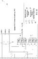
- FIGs. 1 , 2A-2B , and 3A-3B show a satellite navigation receiver 11 capable of receiving signals transmitted by satellites that include one or more carrier signals (e.g., a first carrier (L1), a second carrier (L2) and an additional third carrier (L5) of the Global Positioning System (GPS)) such that the receiver 11 can determine position, velocity, and time with very high accuracy and precision based on the received signals.
- the received signals may be transmitted from one or more satellites, such as a GPS satellite, a Galileo-compatible satellite, or a Global Navigation Satellite System (GLONASS) satellite.
- the satellites have known orbital positions versus time that can be used to estimate the relative position between an antenna 19 of the receiver 11 and each satellite, based on the propagation time of one or more received signals between three or more of the satellites and the antenna 19 of the receiver 11.
- CD shall refer to code and "CR” shall refer to the carrier of the received signal or a digital representation of one or more samples of the received signal.
- the code may include a modulating code (e.g., PN code modulated with information) that modulates the carrier.
- I shall refer to an in-phase signal
- Q shall refer to a quadrature phase signal.
- the receiver 11 described herein may comprise a computer-implemented system or method in which one or more data processors process, store, retrieve, and otherwise manipulate data via data buses and one or more data storage devices (e.g., accumulators or memory) as described in this document and the accompanying drawings.
- data processors process, store, retrieve, and otherwise manipulate data via data buses and one or more data storage devices (e.g., accumulators or memory) as described in this document and the accompanying drawings.
- data storage devices e.g., accumulators or memory
- "configured to, adapted to, or arranged to” mean that the data processor or receiver 11 is programmed with suitable software instructions, software modules, executable code, data libraries, and/or requisite data to execute any referenced functions, mathematical operations, logical operations, calculations, determinations, processes, methods, algorithms, subroutines, or programs that are associated with one or more blocks set forth in FIGs.
- receiver 11 comprises one or more components described herein as software modules, equivalent electronic hardware modules, or both to execute any referenced functions, mathematical operations, calculations, determinations, processes, methods, algorithms, subroutine.
- any arrow or line that connects any blocks, components, modules, multiplexers, memory, data storage, accumulators, data processors, electronic components, oscillators, signal generators, or other electronic or software modules may comprise one or more of the following items: a physical path of electrical signals, a physical path of an electromagnetic signal, a logical path for data, one or more data buses, a circuit board trace, a transmission line; a link, call, communication, or data message between software modules, programs, data, or components; or transmission or reception of data messages, software instructions, modules, subroutines or components.
- a correction wireless device 50 (e.g., transceiver or receiver of satellite or cellular signals) is coupled to the receiver 11, such as to a navigation estimator 62.
- the correction wireless device 50 can receive correction data or differential correction data in the spatial, phase domain that is based on measured range data or carrier phase data from one or more local reference stations.
- the correction data may incorporate or provide precise satellite orbit and clock corrections, rather than normal satellite broadcast information (ephemeris data or other demodulated data provided by demodulating the code (e.g., C/A or course acquisition code for GPS)), on one or more satellite signals to determine a relative position or absolute position of a mobile user satellite navigation receiver (e.g., a rover receiver).
- the rover receiver may use code phase estimates to provide a rough estimate of the position or pseudo-range of the rover receiver with respect to one or more satellites that can be used to reduce the search space for convergence on the carrier phase solution and resolution of the carrier phase ambiguity.
- the estimated integer ambiguity may be subject to a high variance or error than is required for precise carrier phase navigation within a few centimeters of accuracy.
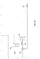
- the receiver 11 may include an analog receiver portion 10 coupled to a digital receiver portion 20.
- the analog receiver portion 10 includes an antenna 19 and a radio frequency (RF) front end 12.
- the receiver 11 receives a signal that comprises a plurality of carrier signals from a satellite.
- the digital receiver portion 20 includes the portion of the receiver 11 that processes data after the analog-to-digital conversion of the received signal by an analog-to-digital converter (ADC) 14.
- ADC analog-to-digital converter
- the digital receiver portion 20 can include an electronic data processor 152, a data storage device 154 (e.g., electronic memory), and a data bus 150 for communication between the electronic data processor 152 and the data storage device 154, where software instructions and data are stored in the data storage device 154 and executed by the data processor 152 to implement any of the blocks, components or modules (e.g., electronic modules, software modules, or both) illustrated in FIGs. 1 , 2A-2B , and 3A-3B .
- the receiver 11 may be capable of: (a) determining a location of the antenna 19, (b) determining a range or distance between the antenna 19 and a satellite; and/or (c) determining ranges between the antenna 19 and one or more satellites.
- a process 400 using the receiver 11 that may receive and process a received signal from a satellite to estimate carrier corrective control data and code corrective control data is shown in FIG. 4 .
- the RF front end 12 of the analog receiver portion 10 receives the signal(s) detected by the antenna 19 that have been transmitted from one or more satellites.
- the RF front end 12 includes an amplifier, a down-conversion mixer, and a local oscillator (not shown).
- the amplifier may be an RF or microwave amplifier (e.g., low noise amplifier) that is coupled to the antenna 19.
- the amplifier may provide an amplified signal to the down-conversion mixer as a first input.
- the local oscillator may provide a signal to the down-conversion mixer as a second input.
- the down-conversion mixer moves or lowers the signal spectrum of the received signal from RF to an intermediate frequency (IF) or a baseband frequency, such as at step 402 of the process 400 shown in FIG. 4 .
- the down-conversion system may include one or more mixing, amplifying, and filtering stages, as in known in the art.
- the output of the down-conversion mixer in the RF front end 12 is coupled to the ADC 14.
- the ADC 14 converts the analog intermediate frequency signal or analog baseband signal to a digital signal, such as at step 404 of the process 400.
- the digital signal may include one or more digital samples that are available at a sampling rate. Each sample may have a finite quantization level and each sample may be capable of being processed by an electronic data processing system, e.g., the digital receiver portion 20 of the receiver 11.
- the output of the analog receiver portion 10 may be coupled to an optional digital interface 16.
- the digital interface 16 may include buffer memory (not shown) that can temporarily store the output of the ADC 14 for processing by the digital receiver portion 20.
- the digital interface 16 may also include a digital filter that filters one or more down-converted carrier signals.
- the digital filter may be a band-pass filter 18 that provides a filtered L1 carrier signal, a filtered L2 carrier signal, and a optional filtered L5 carrier signal.
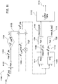
- the digital signal output by the ADC 14 or the filtered carrier signals output from the band-pass filter 18 is input into the digital receiver portion 20 of the receiver 11, and in particular to a baseband module 17.
- the digital signal or filtered carrier signals may be received by a first CD/CR correlation module 22, a second CD/CR correlation module 26, and a third CD/CR correlation module 30, respectively.
- Each CD/CR correlation module 22, 26, 30 may include a carrier wipe-off module 226, a bank of local code replica with various phase shifts with respect to the input signal, and a bank of corresponding integrate and dump (I & D) modules 224, as shown in FIG. 3A .
- the carrier wipe-off module 226 can convert the digital samples of the digital signal to an exact baseband digital signal representation by removing the residual CR frequency.
- Each CD/CR correlation module 22, 26, 30 can be associated with a different carrier frequency or frequency range for the received satellite signal, such as the first carrier frequency (e.g., LI), the second carrier frequency (e.g., L2), and the optional third carrier frequency (e.g., L5).
- Local signal generators 24, 28, 32 (e.g., including numerically controlled oscillator (NCO) modules 228, 230 for each carrier frequency, as shown in FIG. 3 ) provide a local estimation of CR phase and CD phase for each digital sample, such as at step 406 of the process 400, which is used to remove the residual CR frequency and phase and residual CD phase in the sample.
- the carrier wipe-off module 226 outputs I and Q components of the digital signal for input into the bank of correlators that consists of a bank of code demodulators 222 and corresponding I & D modules 224 within each of the CD/CR correlation modules 22, 26, 30.
- the local signal generators 24, 28, 32 is adapted to generate local reference carrier and code signals that include the CR phase and CD phase for each digital sample.
- Each local signal generator 24, 28, 32 is associated with a set of different carrier and code signals within the digital composite received signal.
- the local signal generators 24, 28, 32 generate the local reference carrier and code signals based on carrier corrective control data and code corrective control data from an aggregate predictive filter 42.
- the aggregate predictive filter 42 may be driven by a sigma rho filtering algorithm, as described below.
- an output of the carrier wipe-off module 226 may be fed into a bank of correlators.
- the bank of correlators consists of a bank of the code demodulator 222 and a corresponding I & D module 224.
- the bank of code demodulators 222 may generate multiple codes with various phase shifts against the input signal.
- the bank of correlators has multiple outputs that are used to synchronize the local CD phase, CR frequency, and CR phase estimation with the received samples.
- each correlator may include one or more of the following modules: one or more CR wipe-off portions, a bank of CD wipe-off modules and corresponding I & D modules, and/or one or more multipliers or mixers.
- a module may comprise hardware and/or software.
- each correlator can maximize a correlation between the received signal with a locally generated code by synchronizing the locally generated CD phase with the CD phase in digital sample or digital signal.
- multiple locally generated CD signals e.g., early (E), prompt (P), and late (L) CD signals
- E early
- P prompt
- L late
- CD signals may be used to form a corresponding CD misalignment signal using various discriminator functions.
- Each local signal generator 24, 28, 32 may include a separate code signal generator and a carrier signal generator, for example.
- Each code signal generator 228 may generate a locally generated replica of a pseudo random noise code, a pseudo noise (PN) code sequence, or the like.
- the code signal generator 228 may be associated with a shift register or another device to provide multiple outputs that are offset in time or phase with respect to each other.
- the code signal generator 228 may have an early output (E), a prompt output (P), and a late output (L) that are provided to the set of correlators.
- the early output may provide an early PN code that is advanced against the current estimated code phase by a known time period (e.g., one half chip); the prompt output may provide a prompt PN code that reflects the current estimated code phase; and the late output may provide a late PN code that is delayed in time with respect to the prompt PN code by a known time period (e.g., one half chip).
- the receiver 11 may adjust the phase and time delay (e.g., via shift registers) of the locally generated replica in an attempt to maximize correlation, for example.
- the code signal generator 228 may include any generator for generating a spread spectrum code, spread spectrum sequence, binary sequences, Gold codes, a PN code, a pseudo-random noise code sequence; a PN code that is similar to a spread spectrum code, spread spectrum sequence, binary sequences, Gold codes, pseudo-random noise code, pseudo-random noise code sequence; or a PN code transmitted by a transmitter of a satellite for reception by the receiver 11 as the composite received signal.
- the code signal generator 228 may include a series of shift registers that are loaded with an initial starting code sequence. The shift registers may have various selectable or controllable taps for providing feedback and reiterative values as the output.
- three versions (E, P, L) of a PN code from the code signal generator 228 can interact with the two versions (I, Q) of the received signals of each carrier to produce various permutations of local replica signals to generate different correlations through the integration-and-dump module 224.
- a bank of correlations, which is outputted by the correlators, may be used for decoding, demodulating, and CD and CR phase tracking.
- the CD/CR correlation modules 22, 26, 30 generate multi-frequency correlations (e.g., CORR L1, CORR L2, and CORR L5) for each satellite, such as at step 408 of the process 400.
- the correlation products at each frequency may measure the single distance between a specific satellite and the receiver 11. Therefore, the range measurements at each frequency can contain redundant information. Due to frequency-selective effects, such as the influence of the ionosphere, the correlation range measurements at one frequency may be slightly different from the correlation range measurements at another frequency.
- the correlations may be output from the CD/CR correlation modules 22, 26, 30 over a data bus 65, for example, and be processed by an aggregate predictive filter 42 that is adapted to estimate and provide carrier corrective control data and code corrective control data (labeled as outputs CR_CTRL and CD_CTRL, respectively), such as at step 410 of the process 400.
- the carrier corrective control data and code corrective control data from the aggregate predictive filter 42 consists of a frequency-independent part and a frequency-selective part.
- the frequency-independent control data is provided at a reference frequency, which is scaled to each individual frequency through a scale module as 64, 66, 68, 70, 72, 74.
- the frequency-selective part is estimated individually at each frequency to account for effects such as ionospheric divergence.
- the scaled carrier corrective control data and scaled code corrective control data is provided as feedback to the local signal generators 24, 28, 32 for use at step 406.
- the carrier corrective control data and the code corrective control data may include, for example, an estimated code phase, an estimated carrier phase at a reference frequency, a Doppler shift, a rate of change of the Doppler shift, a strength of the plurality of carrier signals, and/or an amplitude of the plurality of carrier signal.
- the aggregate predictive filter 42 utilizes every available correlation, the common component embedded in the correlation provides the redundancy. Such redundancy can improve performance of the receiver 11 in a frequency-selective fading environment, i.e., the aggregate predictive filter 42 can use correlations on the frequency with the least impact to update the signal generators 24, 28, 32 regardless of the quality of their own correlations.
- the receiver 11 having the fixed point aggregate predictive filter 42 described herein is therefore well-suited to provide reliable position, range, and velocity estimates in the presence of frequency-selective interference and/or fading or low signal strength of the satellite signals.
- the aggregate predictive filter 42 may include a fixed point sigma rho filter that is based on a modified extended Kalman filter.
- the aggregate predictive filter 42 may utilize a standard deviation term (sigma parameter) and a cross correlation term (rho parameter) to improve the numerical stability of the filter. This is in contrast to a typical extended Kalman filter that uses a covariance matrix.
- the numerical range of computations of the parameters of the aggregate predictive filter 42 may accordingly be reduced by a factor of a square root.
- the aggregate predictive filter 42, the local signal generators 24, 28, 32, and the frequency scaling modules 64, 66, 68, 70, 72, 74 may form carrier tracking modules and code tracking modules or a joint tracking module as the aggregate predictive filter 42.
- the carrier tracking modules and the code tracking modules may collectively be referred to as the tracking module.
- the tracking module can support the measurement of the CR frequency, CR phase, and CD phase (individually or collectively) of the received signals to control one or more locally generated reference signals with respect to corresponding received signals (derived from the composite received signal) such that the correlation of the corresponding received signals to the respective locally generated reference signals is maximized.
- the receiver 11 may receive four received signals from at least four different satellite transmitters to estimate the position (e.g., in three spatial dimensions) of the antenna 19.
- the individual code and carrier tracking module or the joint tracking module can generate measurement data that the receiver 11 uses to control an adjustable time delay (e.g., routing data through known number or sequence of shift registers), and/or engage in other data processing of one or more digital signals associated with a locally generated reference signal with respect to the received signal to maximize the correlation of each received signal to the corresponding locally generated reference signal.
- an adjustable time delay e.g., routing data through known number or sequence of shift registers
- the multi-frequency correlations resulting from CD/CR correlation modules 22, 26, 30 are processed by the aggregate predictive filter 42.
- the aggregate predictive filter 42 can be realized using a sigma rho filtering algorithm and may include a carrier phase error detector, a frequency error detector, and a code error detector.
- the aggregate predictive filter 42 functions as a multi-frequency joint code and carrier tracking filter that replaces the multiple tracing loops in a conventional receiver that includes a code loop, a carrier frequency loop, and a carrier phase loop.
- a carrier tracking component of the aggregate predictive filter 42 may facilitate the alignment of the phase of the locally generated replica of the CR to the received signal.
- Carrier control data 77 to the local signal generators 24, 28, 32 adjusts the locally generated replica signal of the CR produced by the carrier NCO module 230.
- the carrier NCO module 230 may provide a locally generated replica of the carrier to the carrier wipe-off module 226.
- the carrier NCO module 230 may receive a carrier phase correction signal and output an adjusted clock signal or another control signal for generating the locally generated CR frequency that accurately aligns with the CR phase or the residual carrier phase of the received sample.
- the code tracking component of the aggregate predictive filter 42 may facilitate the alignment of the phase of the locally generated PN replica with respect to the received sample.
- the code tracking component provides control data 75 to adjust the local signal generators 24, 28, 32, where the code NCO module 228 can control the chipping rate of the local signal generator 24, 28, 32.
- the code tracking module which conventionally comprises a delay locked loop (DLL), may generate a control signal to tune the chipping rate of code NCO module 228.
- the CD phase i.e., the output of code NCO module 228) may be used to drive the local signal generator 24, 28, 32.
- Multiple local PN sequences may be generated by the local signal generator 24, 28, 32.
- the local PN waveform can advance, synchronize, or delay its phase against the CD phase of the received sample.
- a local signal generator may drive a carrier measurement module and a code measurement module.
- the carrier measurement module may include a CR phase counter which may count both the number of integer cycles plus the fractional cycles of the received CR during a known time period.
- the code measurement module may include a millisecond counter, a chip counter, and a fractional chip counter, where the combination of those counters may provide the pseudo range measurement.
- a data demodulator 222 may provide satellite navigation data for estimating a range (e.g., distance between a satellite and the antenna 19) or a position (e.g., in two or three dimensional coordinates) of the phase center of the antenna 19.
- the satellite navigation data or other signal information may include one or more of the following information that modulates the baseband waveform of the received signal: date, satellite navigation system time, satellite status, orbital data, ephemeris data, almanac, satellite location, and/or satellite identifier.
- the data demodulator 222 may use phase shift keying, phase demodulation, pulse width demodulation, amplitude demodulation, quadrature amplitude demodulation, or another demodulation technique that is consistent with the modulation by the modulator at the satellite transmitter.
- the data demodulator 222 can output a demodulated signal or demodulated encoded data, such as a demodulated digital signal with a quadrature phase component and an in-phase component at baseband.
- the data may include one or more following information such as date, satellite navigation system time, satellite status, orbital data, ephemeris data, almanac, satellite location, and/or satellite identifier.
- the measurement generation module 101, 102, 105 or the local signal generators 24, 28, 32 may estimate the propagation time between transmission of a satellite signal from a certain satellite to the antenna 19.
- the navigation estimator 62 may convert the propagation time into a distance or range proportional to the speed of light, using a position estimator 58 and/or velocity estimator 60.
- the navigation estimator 62 may also determine a range, pseudo-range, or estimated range between the antenna 19 and four or more satellites with a reliable signal quality or signal strength based upon one or more of the following: (a) the measured CD phase of each received signal, and/or (b) the measured CR phase of each received signal.
- the navigation estimator 62 or digital receiver portion 20 may resolve ambiguities in the measured CR phase of the received signal by searching for a solution that is consistent with one or more of the following: (1) a position estimated from decoding the code portion of the signal, (2) a known reference position of the antenna 19, and/or (3) differential correction data applicable to the received signal.
- the navigation estimator 62 may be associated with a wireless receiver (e.g., satellite receiver, mobile transceiver, or cellular transceiver) that receives navigation correction data from a reference satellite navigation receiver to reduce or eliminate sources of bias or error (e.g., certain clock errors or propagation errors) in the CR phase measurements.
- a wireless receiver e.g., satellite receiver, mobile transceiver, or cellular transceiver
- the navigation estimator 62 can determine the position estimate of the antenna 19 based on the measured CR phases, estimated ranges, and demodulated data. For example, the navigation estimator 62 may use ranges from four or more satellites to determine the position, velocity, or acceleration of the antenna 19 of the receiver 11 in two or three dimensions.
- the receiver 11 may include hardware and/or software instructions.
- the hardware may include a data processor that communicates to a data storage device, which stores software instructions, via one or more data buses.
- the data processor may include one or more of the following: an electronic data processor, a microprocessor, a microcontroller, an application specific integrated circuit (ASIC), digital signal processor (DSP), a programmable logic device, an arithmetic logic unit, or another electronic data processing device.
- the data storage device may comprise electronic memory, registers, shift registers, volatile electronic memory, a magnetic storage device, an optical storage device, or any other device for storing data.
- the data processor may be coupled to the data storage device via one or more data buses, which support communication between the data processor and the data storage device.
- the data processor may refer to one or more components or modules of the digital receiver portion 20, including but not limited to any of the following: the carrier wipe-off module 226, the code wipe-off module, the integration-and-dump module 224, the bank of correlators, the local signal generators 24, 28, 32, code tracking module, carrier tracking module, measurement generation module 101, 102, 105, data demodulator 222, and navigation estimator 62.
- the digital receiver portion 20 may include a computer or an electronic data processing system that includes an electronic data processor, digital logic circuits, multiplexers, multipliers, digital filters, integrators, delay circuits, oscillator, signal generator, PN code sequence generators, registers, shift registers, logic gates, and/or other hardware.
- the electronic data processing system may support storage, retrieval and execution of software instructions stored in a data storage device.
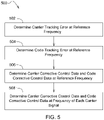
- the aggregate predictive filter 42 may utilize a process 500 shown in FIG. 5 to estimate the carrier corrective control data and the code corrective control data.
- the process 500 is an embodiment of step 410 of the process 400 described above.
- a carrier tracking error is determined at a reference frequency from the plurality of correlations received by the aggregate predictive filter 42 from the CD/CR correlation modules 22, 26, 30.
- the carrier tracking error is determined by a carrier loop discriminator.
- a code tracking error is determined at the reference frequency, such as at step 504, from the plurality of correlations.
- the code tracking error is determined by a code loop discriminator.
- the carrier tracking error and the code tracking error is utilized by a joint estimator to estimate the carrier corrective control data and the code corrective control data.
- the carrier corrective control data and the code corrective control data are determined at the reference frequency, based on the carrier tracking error and the code tracking error from steps 502 and 504.
- the carrier corrective control data and the code corrective control data are estimated at a frequency of each of the carrier signals, such as at step 508, based on the carrier tracking error and code tracking error from steps 502 and 504.
- the carrier corrective control data and the code corrective control data at the reference frequency and at the frequency of each of the carrier signals are provided for use at step 406 of the process 400 by the local signal generators 24, 28, 32.
- n the sampling epoch
- i , j , and k the index of either the row or column of an element in a matrix or a vector
- N the number of an element in a state vector
- x a state vector
- a normalized state vector a symmetric truncation (i.e., a symmetric right shift) calculation
- a fixed point sigma rho filter can be modeled by a set of notation of the extra bit to each variable.
- equation (2) illustrates that p-bit precision is applied on the variable or vector x k .
- the bit of precision can be represented by g, p, s, t, h, q, 1, v, and r. Accordingly, each variable at FIG. 7 is also noted with the precision bits, for example "bt" indicates the corresponding variable has a precision of t bits.
- modules 715, 720, 722, 724, 726, 730, 732, 734, 737, 739 and 741 may represent identical or different mathematical computations.
- modules 715, 720, 722, 724, 726, 730, 732, 734, 737, 739 and 741 may represent identical or different mathematical computations.
- Each of the modules will be modeled through mathematical equations in the following sections.
- the cyclic process 700 in FIG. 7 is driven by a pair of propagations named the dynamic propagation and the measurement update, similar to a conventional Kalman filter.
- the aggregate predictive filter 42 may propagate a triplet ( ⁇ , ⁇ ), which represents a normalized state 701, correlation coefficients 702, and a standard deviation 703, respectively.
- the normalized state 701 is a standard deviation vector to the state vector 703;
- the correlation coefficients 702 are a symmetric matrix denoting the correlation between any of the two states in the normalized state 701; and the standard deviation 703 is a state vector.
- the following sections utilize FIG. 7 to describe the cyclic propagation of the aggregate predictive filter 42.
- the parameters of the sigma rho filter can be configured with initial conditions resulting from the signal detection part.
- ⁇ B t 704 denotes the constant base transition matrix with t bit precision
- ⁇ +, h 701 with precision of h bit may be initialized with the default standard deviation to the normalized state x +, s - h which has a precision of s - h bits.
- the normalized state x +, s - h may be initialized according to the output from the coarse estimation stage, e.g., the signal detection stage.
- any parameter with a superscript "-" indicates the resultant value from the dynamic propagation
- any parameter with a superscript "+” indicates the result of the measurement update.
- a dashed line represents a matrix-based calculation
- a dotted line represents a vector-based calculation
- a solid line represents a scalar-based operation.
- the cyclic propagation starts with the dynamic propagation, where the initial system transition matrix ⁇ B t with t bit precision may be updated with the latest standard deviation of one state 701-1 and the standard deviation of another state 701-2.
- the updated transition matrix ⁇ n l may be combined with the correlation coefficients matrix 702 using the multiplier 710.
- the temporary result 708 has a precision of 2l + q bits. Therefore, a scale unit 709 can be applied to adjust the result with q bit precision.
- equation (2) three matrices are multiplied before a symmetric truncation of 2l bits.
- the precision of the normalized transition matrix ⁇ n l and the cross-correlation function ⁇ n + , q may be limited due to the result of having 2l + q bits for the matrix Q xx , n + 1 ⁇ , q .
- variable g in equation (4) may be selected to be q 2 in some embodiments to simplify the calculation.
- This function may be symbolized by a function module 715 in FIG. 7 .
- a shift function 717 can scale the cross correlation term into a precision of q bits.
- a multiplier 719 may combine the transition matrix ⁇ n l with the normalized state vector with the scale diagonal matrix of ⁇ ⁇ , q 2 (equation (9)).
- the right shift module 717 may scale the resultant state vector to r-h bits.
- Equation (4) includes an adaptive scale factor ⁇ g to approximately calculate the scale factor ⁇ i ⁇ , q 2 , which is used for the cross-correlation update ⁇ - at the dynamic propagation stage shown in equation (7).
- the adaptive scale factor ⁇ g is helps to bound the cross correlation update ⁇ - . Bounding the coefficients of the cross-correlation function ⁇ ij ⁇ within one can help the aggregate predictive filter 42 to be stable and reliable.
- equations (4), (5), and (7) described above do not unconditionally guarantee that the coefficients of the cross-correlation function ⁇ ij ⁇ ⁇ 1 . Accordingly, the coefficients of the cross-correlation function ⁇ ij ⁇ in the dynamic propagation stage may be bounded within an upper limit of ⁇ LIM ⁇ which can be chosen based on simulations, for example.
- the coefficients of the cross-correlation function ⁇ ij ⁇ may be bounded according to the equation: ⁇ ij ⁇ ⁇ Q xx , ij ⁇ 1 + Q xx , ii ⁇ 1 + Q xx , jj ⁇ ⁇ LIM ⁇ ⁇ ⁇ 2 ⁇ Q xx , i , j ⁇ LIM ⁇ 1 + Q xx , ii 1 + Q xx , jjj
- the variable ⁇ 2 may be associated with a set of a priori elements of the matrices Q xx , ij , Q xx , ii , Q xx , jj , and the upper limit ⁇ LIM ⁇ .
- the fixed point representation of equation (10) may be defined by the equation: ⁇ ij 2 q ⁇ ⁇ 2 q ⁇ LIM ⁇ Q xx , ij q 2 q 2 + Q xx , ii q 2 q 2 2 q 2 + Q xx , jj q 2 q 2 ⁇ where 2 q 2 ⁇ 1 ⁇ ⁇ ij q 2 ⁇ 2 q 2 .
- FIG. 9 illustrates the calculation of equation (11) where a multiplier 903 combines the signal 901 and signal 902 to create the numerator of equation (11).
- the expansion of the denominator of equation (11) may be achieved through an arithmetic module including a multiplier 907, adders 908 and 910, and a right shift module 909, according to one embodiment.
- a divider 911 can combine the numerator and denominator to create an integer quotient which is processed by a square root module 912 to obtain one element of ⁇ ij q 2 in equation (11).
- the maximum ⁇ q 2 915 may be selected by the module 913.
- the unit 914 can be used to cap the maximum ⁇ q 2 utilized for equation (10).
- FIG. 10 illustrates an alternative algorithm where (1) the scale factor 915 can be initialized through by a default value 1008; and (2) the cross correlation term 1001 may calculated sequentially. Each absolute value of the signal 1001 may be compared with the current maximum cross correlation coefficient 1002, and the greater value can be used to update the signal 1002. Therefore, the signal 1002 may be the maximum absolute cross correlation coefficient, which is compared with a selected threshold ⁇ LIM ⁇ through the comparators 1004 and 1005.
- the comparators 1004 and 1005 can generate a selection signal 1006 which controls a multiplexer 1007 to update the scale factor 915 with one of the three candidates 915, 1010, and 1011. If the maximum cross correlation coefficient 1002 is greater than the threshold ⁇ LIM ⁇ , the scale factor 915 may be increased by Ups (i.e., updated using signal 1010); if the maximum cross correlation coefficient 1002 is less than the threshold ⁇ LIM ⁇ , the scale factor 915 may be decreased by Dns (i.e., updated using signal 1011); otherwise, the current scale factor 915 may be kept constant.
- Equation (12) may be realized using a function module 720 and a right shift 721 of FIG. 7 .
- the observation matrix H i h may be computed based on a base observation matrix of H B , i t , which is a constant matrix with terms relating to shift, velocity, and acceleration.
- the innovation signal 747 may be calculated which denotes the deviation of the system predicted error 746 against the discriminator observed error signal 755.
- the system predicted measurement y ⁇ n + 1 r may then be determined with the unit 734, according to the equation:
- the measurement update for the standard deviation and cross-correlation functions may be determined by the observation matrix H i h from equation (12), ⁇ h from equation (6), and ⁇ q from equation (7).
- the output of the scale factor unit 725 may be added by an user-defined observation noise matrix R q to achieve the sum ( ⁇ 2 ) q .
- the operations of equation (17) may be performed by a function unit 736.
- variable ⁇ i 2 q is the key parameter to propagate the cross correlation and standard deviation at the measurement update stage, such as at step 618 of the process 600.
- the range of the variable ⁇ i 2 q may play an important role for the stability of the cross correlation and standard deviation propagation.
- 1 1 ⁇ ⁇ i 2 is used to propagate the cross correlation.
- the variable ⁇ i 2 is required to be less than 1 (to make the square root calculation valid) but not too close to 1 (to make the inverse calculation stable). Therefore, a rescale parameter ⁇ can be introduced to bound the variable ⁇ i 2 within an appropriate range.
- equation (20) may calculate the rescale parameter ⁇ by dividing the predetermined upper limit ⁇ LIM 2 q by a maximum of the variable ⁇ i 2 q .
- Equation (21) may calculate the measurement update of the standard deviation function ⁇ i + based on multiplying the dynamic update of the standard deviation function ⁇ - and the variable ⁇ i + , q 2 from equation (22), followed by a symmetric truncation of q 2 bits.
- ⁇ i q 2 in equation (23) may be obtained through looking up a square root table 728 based on the input of ⁇ i 2 q .
- a square root table is a reasonable implementation as ⁇ LIM 2 q is the maximum value that ⁇ i 2 q can reach.
- a function unit 732 may inverse ⁇ i + , q 2 based on equation (24), which is combined with ⁇ ij ⁇ , q and ⁇ i q 2 through equation (23).
- the output of the function unit 732 is symmetrically truncated by q bits using a scale factor unit 733.
- the selection of the scale factor ⁇ to compute 1 ⁇ ⁇ i 2 q 2 in equation (22) is important to guarantee: (1) the stability of standard deviation propagation (equation (22)) such that ⁇ i 2 q ⁇ ⁇ LIM 2 q , ⁇ i ; and (2) the stability of cross correlation propagation (equation (23)) as the selection of ⁇ impact the calculation of 1 ⁇ i + q 2 , thus affecting the range of cross correlation at measurement update.
- Equation (25) can calculate the measurement update of the cross-correlation function ⁇ ij + based on the dynamic update of the cross-correlation function ⁇ - and the variable ⁇ i 2 defined by equation (18).
- the adaptive scale factor ⁇ can be determined to ensure that the measurement update of the cross-correlation function ⁇ ij + is bounded within one, due to the approximation to the square root in the denominator of equation (25).
- ⁇ ij ⁇ ⁇ ij 1 if 0 ⁇ ⁇ ij 1 ⁇ 1 0 if ⁇ ij 1 ⁇ 0 1 if ⁇ ij 1 ⁇ 1
- ⁇ ij 1 B ⁇ B 2 ⁇ 4 AC 2 A
- B 2 ⁇ 4 AC ⁇ i 2 + ⁇ j 2 2 ⁇ 4 ⁇ i 3 ⁇ j 3 ⁇ 4 ⁇ i 2 ⁇ j 2 ⁇ 4 ⁇ i 3 4 ⁇ j ⁇ 0
- ⁇ A ⁇ i 2 ⁇ j 2 ⁇ 0
- B ⁇ i 2 + ⁇ j 2 ⁇ 0
- C ⁇ i ⁇ j ⁇ 0
- a numerical solution of the adaptive scale factor ⁇ in equation (27) can be based on a pair of input ( ⁇ i , ⁇ j ) to be evaluated, where ⁇ i ranges from 0 to 1 with a step of 1/32 and ⁇ j is selected from 0 to 1 with a step of 1/32.
- FIG. 11 illustrates the adaptive scale factor ⁇ selection process described above, where the unit 1111 remembers the maximum ⁇ max 1108 within the vector ⁇ ⁇ i ⁇ , and the unit 1109 remembers the minimum ⁇ min 1110 within the vector ⁇ ⁇ i ⁇ .
- a square root table 728 (shown in FIG. 7 ) is a reasonable and convenient implementation to perform the square root operation.
- the resulting pair ⁇ min q 2 ⁇ max q 2 may be the entry for a two-dimensional lookup table 1115 to obtain the minimum argument of the adaptive scale factor ⁇ described by equation (26).
- equation (25) implies that by lowering the range of the adaptive scale factor 0 ⁇ ⁇ ⁇ 1, the cross correlation ⁇ + gets smaller.
- a halve-double method such as at step 624 of the process 600.
- the unit 1202 may take the absolute value of a vector ⁇ ij + , then a selector 1204 may select the maximum ⁇ max + from vector 1203.
- a comparator 1205 can compare ⁇ max + with an upper limit ⁇ UP ⁇ LIM + and a comparator 1206 may compare ⁇ max + with a lower limit ⁇ LO ⁇ LIM + .
- the comparators 1205, 1206 may create a selection signal 1207 which determines whether the adaptive scale factor ⁇ 1116 is kept constant, or is doubled 1209 or halved 1210.
- a function unit 739 may calculate K i h V obs r ⁇ ⁇ cr + , h followed by a scale factor unit 740 to obtain the intermediate results of the second half of equation (31).
- a function unit 741 may calculate 1 ⁇ i + q 2 x i , n + 1 ( ⁇ , r ⁇ h followed by a shift unit 742 to obtain the first half of equation (31). The two parts may be added to generate the state measurement update signal 703.
- the receiver disclosed in this document is well-suited for: (1) utilizing an aggregate predictive fixed point sigma rho filter to improve real time carrier and code tracking of received signals; and (2) implementing the fixed point sigma rho filter using adaptive strategies to control the range of the cross correlation term to ensure the stability and reliability of the filter.
Claims (12)
- Satellitennavigationsempfänger, umfassend:ein Empfänger-Front-End, das zum Abwärtsumwandeln eines zusammengesetzten empfangenen Signals, das mehrere Trägersignale umfasst, ausgeführt ist;ein Analog-Digital-Wandler zum Umwandeln des abwärtsgewandelten zusammengesetzten empfangenen Signals in ein digitales zusammengesetztes empfangenes Signal;mehrere Signalgeneratoren, die jeweils zum Erzeugen eines lokalen Referenzträgersignals und eines lokalen Referenzentfernungsmessungscodes auf Basis von Trägerkorrektur-Steuerdaten und von Codekorrektur-Steuerdaten ausgeführt sind, wobei die Trägerkorrektur-Steuerdaten Trägerkorrektur-Steuerdaten auf einer Referenzfrequenz und Trägerkorrektur-Steuerdaten auf einer Frequenz jedes der mehreren Trägersignale umfassen, die Codekorrektur-Steuerdaten Codekorrektur-Steuerdaten auf der Referenzfrequenz und Codekorrektur-Steuerdaten auf der Frequenz jedes der mehreren Trägersignale umfassen und wobei das lokale Referenzträgersignal und der lokale Referenzentfernungsmessungscode mit einem der mehreren Trägersignale verbunden sind;mehrere Empfängermodule, die jeweils einen Korrelator umfassen, der zum Bestimmen von einem von mehreren Korrelationen des digitalen zusammengesetzten empfangenen Signals mit dem lokalen Referenzträgersignal und dem lokalen Referenzentfernungsmessungscode ausgeführt ist, wobei jede der mehreren Korrelationen eine gleichphasige Korrelation und eine Quadraturkorrelation umfasst und mit einem der mehreren Trägersignale verbunden ist; undein aggregierendes prädiktives Filter, das mit den mehreren Signalgeneratoren in Kommunikation steht, wobei das aggregierende prädiktive Filter zum Schätzen der Trägerkorrektur-Steuerdaten und der Codekorrektur-Steuerdaten auf Basis der mehreren Korrelationen ausgeführt ist, wobei das aggregierende prädiktive Filter die Trägerkorrektur-Steuerdaten und die Codekorrektur-Steuerdaten auf der Referenzfrequenz auf Basis der mehreren Korrelationen schätzt und wobei die Trägerkorrektur-Steuerdaten und die Codekorrektur-Steuerdaten eine Korrektur einer Entfernungsschätzung zwischen dem Empfänger und einem Satelliten repräsentieren, wobei das aggregierende prädiktive Filter umfasst:
einen Trägerschleifendiskriminator, der zum Bestimmen eines Träger-Trackingfehlers bei der Referenzfrequenz anhand der mehreren Korrelationen ausgeführt ist, einen Codeschleifendiskriminator, der zum Bestimmen eines Code-Trackingfehlers bei der Referenzfrequenz anhand der mehreren Korrelationen ausgeführt ist; und einen gemeinsamen Schätzer, der ausgeführt ist zum:Bestimmen der Trägerkorrektur-Steuerdaten auf der Referenzfrequenz und der Codekorrektur-Steuerdaten auf der Referenzfrequenz auf Basis des Träger-Trackingfehlers und des Code-Trackingfehlers; undeinzelnen Schätzen der Trägerkorrektur-Steuerdaten auf der Frequenz jedes der mehreren Trägersignale und der Codekorrektur-Steuerdaten auf der Frequenz jedes der mehreren Trägersignale auf Basis des Träger-Trackingfehlers und des Code-Trackingfehlers;mehrere Skalierungsmodule, die mit dem aggregierenden prädiktiven Filter in Kommunikation stehen, wobei die mehreren Skalierungsmodule jeweils zum jeweiligen Skalieren der Trägerkorrektur-Steuerdaten und der Codekorrektur-Steuerdaten auf der Referenzfrequenz auf skalierte Trägerkorrektur-Steuerdaten und skalierte Codekorrektur-Steuerdaten auf der Frequenz jeder der mehreren Trägersignale ausgeführt sind;wobei die mehreren Signalgeneratoren zum Erzeugen des lokalen Referenzträgersignals und des lokalen Referenzentfernungsmessungscodes auf Basis der skalierten Trägerkorrektur-Steuerdaten und der skalierten Codekorrektur-Steuerdaten ausgeführt sind. - Satellitennavigationsempfänger nach Anspruch 1, wobei:die mehreren Korrelationen jeweils für eine Frequenz von jedem der mehreren Trägersignale sind;das aggregierende prädiktive Filter ferner zum Gewichten von jeder der mehreren Korrelationen auf Basis einer Signalqualitätsmetrik ausgeführt ist.
- Satellitennavigationsempfänger nach Anspruch 2, wobei die Signalqualitätsmetrik eines oder mehrere von einem Signal-Rausch-Verhältnis oder einem gleitenden Mittelwert des Signal-Rausch-Verhältnisses über ein Schiebefenster umfasst.
- Satellitennavigationsempfänger nach einem der vorhergehenden Ansprüche, der ferner einen Navigationsschätzer umfasst, der zum Schätzen von einem oder mehreren von einer Position oder einer Geschwindigkeit auf Basis einer Phase eines lokalen Referenzträgersignals und einer Phase des lokalen Referenzentfernungsmessungscodes ausgeführt ist.
- Satellitennavigationsempfänger nach einem der vorhergehenden Ansprüche, wobei das aggregierende prädiktive Filter ein Festkomma-Sigma-Rho-Filter umfasst, das zum Schätzen der Trägerkorrektur-Steuerdaten und der Codekorrektur-Steuerdaten ausgeführt ist, wobei die Trägerkorrektur-Steuerdaten und die Codekorrektur-Steuerdaten eine oder mehrere von einer geschätzten Codephase, einer geschätzten Trägerphase bei einer Referenzfrequenz, einer Doppler-Verschiebung, einer Änderungsrate der Dopplerverschiebung, einer Stärke der mehreren Trägersignale oder einer Amplitude der mehreren Trägersignale umfassen.
- Satellitennavigationsempfänger nach einem der vorhergehenden Ansprüche, wobei das aggregierende prädiktive Filter ein Festkomma-Sigma-Rho-Filter umfasst, das zum Schätzen der Trägerkorrektur-Steuerdaten und der Codekorrektur-Steuerdaten unter Verwendung einer dynamischen Ausbreitungsstufe und einer Messungsaktualisierungsstufe auf Basis einer Standardabweichungsfunktion (Sigma) und einer Kreuzkorrelationsfunktion (Rho) ausgeführt ist.
- Satellitennavigationsempfänger nach Anspruch 6, wobei das Festkomma-Sigma-Rho-Filter die Trägerkorrektur-Steuerdaten und die Codekorrektur-Steuerdaten durch dynamisches Auswählen eines adaptiven Skalierungsfaktors η schätzt, um Koeffizienten der Kreuzkorrelationsfunktion auf Basis vorheriger Koeffizienten während der dynamischen Ausbreitungsstufe der Kreuzkorrelationsfunktion auf innerhalb eins zu beschränken.
- Satellitennavigationsempfänger nach Anspruch 6, wobei das Festkomma-Sigma-Rho-Filter die Trägerkorrektur-Steuerdaten und die Codekorrektur-Steuerdaten durch Auswählen eines Reskalierungsparameters γ schätzt, um einen Parameter β auf Basis einer vorbestimmten Obergrenze während der Messungsaktualisierungsstufe auf weniger als eins zu begrenzen.
- Satellitennavigationsempfänger nach Anspruch 6, wobei das Festkomma-Sigma-Rho-Filter die Trägerkorrektur-Steuerdaten und die Codekorrektur-Steuerdaten durch Bestimmen eines adaptiven Skalierungsfaktors µ schätzt, um Koeffizienten der Kreuzkorrelationsfunktion während der Messungsaktualisierungsstufe auf innerhalb eins zu begrenzen, wobei der adaptive Skalierungsfaktor aus einem von mehreren in einer Lookup-Tabelle gespeicherten vorbestimmten Skalierungsfaktoren auf Basis von Indizes βi und βj ausgewählt ist.
- Satellitennavigationsempfänger nach Anspruch 6, wobei das Festkomma-Sigma-Rho-Filter die Trägerkorrektur-Steuerdaten und die Codekorrektur-Steuerdaten durch Bestimmen eines adaptiven Skalierungsfaktors µ schätzt, um Koeffizienten der Kreuzkorrelationsfunktion während der Messungsaktualisierungsstufe auf innerhalb eins zu begrenzen, wobei der adaptive Skalierungsfaktor bestimmt wird durch:Verdoppeln des adaptiven Skalierungsfaktors, bis ein vorbestimmter Höchstwert erreicht wird, falls ein maximaler Koeffizient der Kreuzkorrelationsfunktion größer ist als eine vorbestimmte obere Schwelle; undHalbieren des adaptiven Skalierungsfaktors, falls der maximale Koeffizient der Kreuzkorrelationsfunktion kleiner ist als eine vorbestimmte untere Schwelle.
- Satellitennavigationsempfänger nach einem der vorhergehenden Ansprüche, wobei die mehreren Trägersignale einen ersten Träger (L1), einen zweiten Träger (L2) und einen dritten Träger (L5) umfassen.
- Satellitennavigationsempfänger nach einem der vorhergehenden Ansprüche:ferner umfassend ein Bandpassfilter, das zum Filtern des digitalen zusammengesetzten empfangenen Signals in mehrere gefilterter Trägersignale, die jeweils mit einem anderen Trägersignal in dem digitalen zusammengesetzten empfangenen Signal verbunden sind, ausgeführt ist;wobei der Korrelator von jedem der mehreren Empfängermodule zum Bestimmen der Korrelation von einem der mehreren gefilterten Trägersignale mit den lokalen Referenzträgersignalen und dem lokalen Referenzentfernungsmessungscode ausgeführt ist.
Applications Claiming Priority (3)
| Application Number | Priority Date | Filing Date | Title |
|---|---|---|---|
| US201562240310P | 2015-10-12 | 2015-10-12 | |
| US14/880,852 US10048385B2 (en) | 2015-10-12 | 2015-10-12 | Satellite navigation receiver with fixed point sigma RHO filter |
| PCT/US2016/054654 WO2017065998A1 (en) | 2015-10-12 | 2016-09-30 | Satellite navigation receiver with fixed point sigma rho filter |
Publications (3)
| Publication Number | Publication Date |
|---|---|
| EP3362818A1 EP3362818A1 (de) | 2018-08-22 |
| EP3362818A4 EP3362818A4 (de) | 2019-10-09 |
| EP3362818B1 true EP3362818B1 (de) | 2022-08-03 |
Family
ID=58517743
Family Applications (1)
| Application Number | Title | Priority Date | Filing Date |
|---|---|---|---|
| EP16855951.6A Active EP3362818B1 (de) | 2015-10-12 | 2016-09-30 | Satellitennavigationsempfänger mit fixpunkt-sigma-rho-filter |
Country Status (4)
| Country | Link |
|---|---|
| EP (1) | EP3362818B1 (de) |
| CN (1) | CN108027442B (de) |
| BR (1) | BR112018004534A2 (de) |
| WO (1) | WO2017065998A1 (de) |
Families Citing this family (4)
| Publication number | Priority date | Publication date | Assignee | Title |
|---|---|---|---|---|
| CN109557568B (zh) * | 2018-11-29 | 2020-10-23 | 湖南国科微电子股份有限公司 | 一种测距码产生方法及装置 |
| CN111045048B (zh) * | 2019-12-30 | 2022-03-11 | 北京航空航天大学 | 一种动态精密单点定位的抗差自适应分步滤波方法 |
| CN113708873B (zh) * | 2021-08-24 | 2023-04-14 | 四川安迪科技实业有限公司 | 低轨卫星tdma静中通系统的返向链路多普勒频移估计方法 |
| CN114157313B (zh) * | 2021-10-25 | 2023-03-03 | 北京遥测技术研究所 | 一种实现glonass三频新体制信号接收的基带电路结构及其方法 |
Family Cites Families (5)
| Publication number | Priority date | Publication date | Assignee | Title |
|---|---|---|---|---|
| US6331835B1 (en) * | 1999-02-02 | 2001-12-18 | The Charles Stark Draper Laboratory, Inc. | Deeply-integrated adaptive GPS-based navigator with extended-range code tracking |
| US20050147191A1 (en) * | 2004-01-02 | 2005-07-07 | Geier George J. | Extended frequency error correction in a wireless communication receiver |
| US7151486B2 (en) * | 2004-07-14 | 2006-12-19 | Lockheed Martin Corporation | GPS navigation with integrated phase track filter |
| US8364401B2 (en) * | 2007-05-29 | 2013-01-29 | Deimos Engenharia S.A. | Highly integrated GPS, Galileo and inertial navigation system |
| US8362949B2 (en) * | 2011-06-27 | 2013-01-29 | Google Inc. | GPS and MEMS hybrid location-detection architecture |
-
2016
- 2016-09-30 EP EP16855951.6A patent/EP3362818B1/de active Active
- 2016-09-30 WO PCT/US2016/054654 patent/WO2017065998A1/en active Application Filing
- 2016-09-30 CN CN201680052717.8A patent/CN108027442B/zh active Active
- 2016-09-30 BR BR112018004534A patent/BR112018004534A2/pt unknown
Also Published As
| Publication number | Publication date |
|---|---|
| EP3362818A1 (de) | 2018-08-22 |
| WO2017065998A1 (en) | 2017-04-20 |
| BR112018004534A2 (pt) | 2018-10-09 |
| CN108027442A (zh) | 2018-05-11 |
| EP3362818A4 (de) | 2019-10-09 |
| CN108027442B (zh) | 2022-11-29 |
Similar Documents
| Publication | Publication Date | Title |
|---|---|---|
| US10859709B2 (en) | Satellite navigation receiver with fixed point sigma rho filter | |
| US7693211B2 (en) | Fast fourier transform based phase locked loop for navigational receivers | |
| CN105917622B (zh) | 用于接收复合信号的方法和接收器 | |
| US8000378B2 (en) | Narrow correlator technique for multipath mitigation | |
| US5414729A (en) | Pseudorandom noise ranging receiver which compensates for multipath distortion by making use of multiple correlator time delay spacing | |
| EP2235553B1 (de) | Verfahren und vorrichtung zur adaptiven verarbeitung von aus satellitennavigationssystemen empfangenen signalen | |
| US6725157B1 (en) | Indoor GPS clock | |
| US7995683B2 (en) | Noise floor independent delay-locked loop discriminator | |
| US6959057B1 (en) | Method of enhancing signal tracking in global positioning system receivers | |
| EP3362818B1 (de) | Satellitennavigationsempfänger mit fixpunkt-sigma-rho-filter | |
| US20070076788A1 (en) | Bit synchronization for weak navigational satellite signals | |
| US20090213912A1 (en) | Multipath mitigation gnss receiver | |
| JP2000511278A (ja) | 位置決定応用のスペクトル拡散受信機における多経路誤差の減少 | |
| US8391339B2 (en) | Correlator sum method for spread spectrum signal receivers | |
| EP3458877B1 (de) | Verfahren und system für satellitensignalverarbeitung | |
| US20100135363A1 (en) | Supporting a Signal Acquisition | |
| US20230213658A1 (en) | Aggregated Vector and Clock Tracking in a GNSS Receiver | |
| US9297905B2 (en) | Method of acquiring CDMA-modulated satellite signals and receiving apparatus implementing the method | |
| US6642885B2 (en) | Receiver for a satellite based position location system | |
| US20120170628A1 (en) | Differential phase shift keying demodulator, receiver apparatus employing the demodulator, and demodulation method | |
| WO2023129543A1 (en) | Aggregated vector and clock tracking in a gnss receiver | |
| EP1240531A1 (de) | Empfänger für ein satellitengestütztes ortungssystem |
Legal Events
| Date | Code | Title | Description |
|---|---|---|---|
| STAA | Information on the status of an ep patent application or granted ep patent |
Free format text: STATUS: THE INTERNATIONAL PUBLICATION HAS BEEN MADE |
|
| PUAI | Public reference made under article 153(3) epc to a published international application that has entered the european phase |
Free format text: ORIGINAL CODE: 0009012 |
|
| STAA | Information on the status of an ep patent application or granted ep patent |
Free format text: STATUS: REQUEST FOR EXAMINATION WAS MADE |
|
| 17P | Request for examination filed |
Effective date: 20180514 |
|
| AK | Designated contracting states |
Kind code of ref document: A1 Designated state(s): AL AT BE BG CH CY CZ DE DK EE ES FI FR GB GR HR HU IE IS IT LI LT LU LV MC MK MT NL NO PL PT RO RS SE SI SK SM TR |
|
| AX | Request for extension of the european patent |
Extension state: BA ME |
|
| DAV | Request for validation of the european patent (deleted) | ||
| DAX | Request for extension of the european patent (deleted) | ||
| RIC1 | Information provided on ipc code assigned before grant |
Ipc: G01S 19/13 20100101ALI20190513BHEP Ipc: G01S 19/01 20100101AFI20190513BHEP Ipc: G01S 19/30 20100101ALI20190513BHEP |
|
| A4 | Supplementary search report drawn up and despatched |
Effective date: 20190911 |
|
| RIC1 | Information provided on ipc code assigned before grant |
Ipc: G01S 19/13 20100101ALI20190905BHEP Ipc: G01S 19/30 20100101ALI20190905BHEP Ipc: G01S 19/01 20100101AFI20190905BHEP |
|
| STAA | Information on the status of an ep patent application or granted ep patent |
Free format text: STATUS: EXAMINATION IS IN PROGRESS |
|
| 17Q | First examination report despatched |
Effective date: 20200707 |
|
| STAA | Information on the status of an ep patent application or granted ep patent |
Free format text: STATUS: EXAMINATION IS IN PROGRESS |
|
| REG | Reference to a national code |
Ref country code: DE Ref legal event code: R079 Ref document number: 602016074037 Country of ref document: DE Free format text: PREVIOUS MAIN CLASS: G01S0019010000 Ipc: G01S0019240000 |
|
| GRAP | Despatch of communication of intention to grant a patent |
Free format text: ORIGINAL CODE: EPIDOSNIGR1 |
|
| STAA | Information on the status of an ep patent application or granted ep patent |
Free format text: STATUS: GRANT OF PATENT IS INTENDED |
|
| INTG | Intention to grant announced |
Effective date: 20220408 |
|
| RIC1 | Information provided on ipc code assigned before grant |
Ipc: G01S 19/30 20100101ALI20220325BHEP Ipc: G01S 19/29 20100101ALI20220325BHEP Ipc: G01S 19/24 20100101AFI20220325BHEP |
|
| RIN1 | Information on inventor provided before grant (corrected) |
Inventor name: HATCH, RONALD R. Inventor name: KEEGAN, RICHARD, G. Inventor name: YU, WEI |
|
| GRAS | Grant fee paid |
Free format text: ORIGINAL CODE: EPIDOSNIGR3 |
|
| GRAA | (expected) grant |
Free format text: ORIGINAL CODE: 0009210 |
|
| STAA | Information on the status of an ep patent application or granted ep patent |
Free format text: STATUS: THE PATENT HAS BEEN GRANTED |
|
| AK | Designated contracting states |
Kind code of ref document: B1 Designated state(s): AL AT BE BG CH CY CZ DE DK EE ES FI FR GB GR HR HU IE IS IT LI LT LU LV MC MK MT NL NO PL PT RO RS SE SI SK SM TR |
|
| REG | Reference to a national code |
Ref country code: AT Ref legal event code: REF Ref document number: 1509191 Country of ref document: AT Kind code of ref document: T Effective date: 20220815 Ref country code: CH Ref legal event code: EP |
|
| REG | Reference to a national code |
Ref country code: DE Ref legal event code: R096 Ref document number: 602016074037 Country of ref document: DE |
|
| REG | Reference to a national code |
Ref country code: IE Ref legal event code: FG4D |
|
| REG | Reference to a national code |
Ref country code: LT Ref legal event code: MG9D |
|
| REG | Reference to a national code |
Ref country code: NL Ref legal event code: MP Effective date: 20220803 |
|
| PG25 | Lapsed in a contracting state [announced via postgrant information from national office to epo] |
Ref country code: SE Free format text: LAPSE BECAUSE OF FAILURE TO SUBMIT A TRANSLATION OF THE DESCRIPTION OR TO PAY THE FEE WITHIN THE PRESCRIBED TIME-LIMIT Effective date: 20220803 Ref country code: RS Free format text: LAPSE BECAUSE OF FAILURE TO SUBMIT A TRANSLATION OF THE DESCRIPTION OR TO PAY THE FEE WITHIN THE PRESCRIBED TIME-LIMIT Effective date: 20220803 Ref country code: PT Free format text: LAPSE BECAUSE OF FAILURE TO SUBMIT A TRANSLATION OF THE DESCRIPTION OR TO PAY THE FEE WITHIN THE PRESCRIBED TIME-LIMIT Effective date: 20221205 Ref country code: NO Free format text: LAPSE BECAUSE OF FAILURE TO SUBMIT A TRANSLATION OF THE DESCRIPTION OR TO PAY THE FEE WITHIN THE PRESCRIBED TIME-LIMIT Effective date: 20221103 Ref country code: NL Free format text: LAPSE BECAUSE OF FAILURE TO SUBMIT A TRANSLATION OF THE DESCRIPTION OR TO PAY THE FEE WITHIN THE PRESCRIBED TIME-LIMIT Effective date: 20220803 Ref country code: LV Free format text: LAPSE BECAUSE OF FAILURE TO SUBMIT A TRANSLATION OF THE DESCRIPTION OR TO PAY THE FEE WITHIN THE PRESCRIBED TIME-LIMIT Effective date: 20220803 Ref country code: LT Free format text: LAPSE BECAUSE OF FAILURE TO SUBMIT A TRANSLATION OF THE DESCRIPTION OR TO PAY THE FEE WITHIN THE PRESCRIBED TIME-LIMIT Effective date: 20220803 Ref country code: FI Free format text: LAPSE BECAUSE OF FAILURE TO SUBMIT A TRANSLATION OF THE DESCRIPTION OR TO PAY THE FEE WITHIN THE PRESCRIBED TIME-LIMIT Effective date: 20220803 Ref country code: ES Free format text: LAPSE BECAUSE OF FAILURE TO SUBMIT A TRANSLATION OF THE DESCRIPTION OR TO PAY THE FEE WITHIN THE PRESCRIBED TIME-LIMIT Effective date: 20220803 |
|
| REG | Reference to a national code |
Ref country code: AT Ref legal event code: MK05 Ref document number: 1509191 Country of ref document: AT Kind code of ref document: T Effective date: 20220803 |
|
| PG25 | Lapsed in a contracting state [announced via postgrant information from national office to epo] |
Ref country code: PL Free format text: LAPSE BECAUSE OF FAILURE TO SUBMIT A TRANSLATION OF THE DESCRIPTION OR TO PAY THE FEE WITHIN THE PRESCRIBED TIME-LIMIT Effective date: 20220803 Ref country code: IS Free format text: LAPSE BECAUSE OF FAILURE TO SUBMIT A TRANSLATION OF THE DESCRIPTION OR TO PAY THE FEE WITHIN THE PRESCRIBED TIME-LIMIT Effective date: 20221203 Ref country code: HR Free format text: LAPSE BECAUSE OF FAILURE TO SUBMIT A TRANSLATION OF THE DESCRIPTION OR TO PAY THE FEE WITHIN THE PRESCRIBED TIME-LIMIT Effective date: 20220803 Ref country code: GR Free format text: LAPSE BECAUSE OF FAILURE TO SUBMIT A TRANSLATION OF THE DESCRIPTION OR TO PAY THE FEE WITHIN THE PRESCRIBED TIME-LIMIT Effective date: 20221104 |
|
| PG25 | Lapsed in a contracting state [announced via postgrant information from national office to epo] |
Ref country code: SM Free format text: LAPSE BECAUSE OF FAILURE TO SUBMIT A TRANSLATION OF THE DESCRIPTION OR TO PAY THE FEE WITHIN THE PRESCRIBED TIME-LIMIT Effective date: 20220803 Ref country code: RO Free format text: LAPSE BECAUSE OF FAILURE TO SUBMIT A TRANSLATION OF THE DESCRIPTION OR TO PAY THE FEE WITHIN THE PRESCRIBED TIME-LIMIT Effective date: 20220803 Ref country code: DK Free format text: LAPSE BECAUSE OF FAILURE TO SUBMIT A TRANSLATION OF THE DESCRIPTION OR TO PAY THE FEE WITHIN THE PRESCRIBED TIME-LIMIT Effective date: 20220803 Ref country code: CZ Free format text: LAPSE BECAUSE OF FAILURE TO SUBMIT A TRANSLATION OF THE DESCRIPTION OR TO PAY THE FEE WITHIN THE PRESCRIBED TIME-LIMIT Effective date: 20220803 Ref country code: AT Free format text: LAPSE BECAUSE OF FAILURE TO SUBMIT A TRANSLATION OF THE DESCRIPTION OR TO PAY THE FEE WITHIN THE PRESCRIBED TIME-LIMIT Effective date: 20220803 |
|
| REG | Reference to a national code |
Ref country code: CH Ref legal event code: PL |
|
| REG | Reference to a national code |
Ref country code: DE Ref legal event code: R097 Ref document number: 602016074037 Country of ref document: DE |
|
| REG | Reference to a national code |
Ref country code: BE Ref legal event code: MM Effective date: 20220930 |
|
| PG25 | Lapsed in a contracting state [announced via postgrant information from national office to epo] |
Ref country code: SK Free format text: LAPSE BECAUSE OF FAILURE TO SUBMIT A TRANSLATION OF THE DESCRIPTION OR TO PAY THE FEE WITHIN THE PRESCRIBED TIME-LIMIT Effective date: 20220803 Ref country code: MC Free format text: LAPSE BECAUSE OF FAILURE TO SUBMIT A TRANSLATION OF THE DESCRIPTION OR TO PAY THE FEE WITHIN THE PRESCRIBED TIME-LIMIT Effective date: 20220803 Ref country code: EE Free format text: LAPSE BECAUSE OF FAILURE TO SUBMIT A TRANSLATION OF THE DESCRIPTION OR TO PAY THE FEE WITHIN THE PRESCRIBED TIME-LIMIT Effective date: 20220803 |
|
| PLBE | No opposition filed within time limit |
Free format text: ORIGINAL CODE: 0009261 |
|
| STAA | Information on the status of an ep patent application or granted ep patent |
Free format text: STATUS: NO OPPOSITION FILED WITHIN TIME LIMIT |
|
| PG25 | Lapsed in a contracting state [announced via postgrant information from national office to epo] |
Ref country code: LU Free format text: LAPSE BECAUSE OF NON-PAYMENT OF DUE FEES Effective date: 20220930 Ref country code: AL Free format text: LAPSE BECAUSE OF FAILURE TO SUBMIT A TRANSLATION OF THE DESCRIPTION OR TO PAY THE FEE WITHIN THE PRESCRIBED TIME-LIMIT Effective date: 20220803 |
|
| 26N | No opposition filed |
Effective date: 20230504 |
|
| PG25 | Lapsed in a contracting state [announced via postgrant information from national office to epo] |
Ref country code: LI Free format text: LAPSE BECAUSE OF NON-PAYMENT OF DUE FEES Effective date: 20220930 Ref country code: IE Free format text: LAPSE BECAUSE OF NON-PAYMENT OF DUE FEES Effective date: 20220930 Ref country code: CH Free format text: LAPSE BECAUSE OF NON-PAYMENT OF DUE FEES Effective date: 20220930 |
|
| PG25 | Lapsed in a contracting state [announced via postgrant information from national office to epo] |
Ref country code: SI Free format text: LAPSE BECAUSE OF FAILURE TO SUBMIT A TRANSLATION OF THE DESCRIPTION OR TO PAY THE FEE WITHIN THE PRESCRIBED TIME-LIMIT Effective date: 20220803 |
|
| PG25 | Lapsed in a contracting state [announced via postgrant information from national office to epo] |
Ref country code: BE Free format text: LAPSE BECAUSE OF NON-PAYMENT OF DUE FEES Effective date: 20220930 |
|
| PGFP | Annual fee paid to national office [announced via postgrant information from national office to epo] |
Ref country code: GB Payment date: 20230927 Year of fee payment: 8 |
|
| PGFP | Annual fee paid to national office [announced via postgrant information from national office to epo] |
Ref country code: FR Payment date: 20230925 Year of fee payment: 8 Ref country code: DE Payment date: 20230821 Year of fee payment: 8 |
|
| PG25 | Lapsed in a contracting state [announced via postgrant information from national office to epo] |
Ref country code: HU Free format text: LAPSE BECAUSE OF FAILURE TO SUBMIT A TRANSLATION OF THE DESCRIPTION OR TO PAY THE FEE WITHIN THE PRESCRIBED TIME-LIMIT; INVALID AB INITIO Effective date: 20160930 |
|
| PG25 | Lapsed in a contracting state [announced via postgrant information from national office to epo] |
Ref country code: CY Free format text: LAPSE BECAUSE OF FAILURE TO SUBMIT A TRANSLATION OF THE DESCRIPTION OR TO PAY THE FEE WITHIN THE PRESCRIBED TIME-LIMIT Effective date: 20220803 |