EP3362816B2 - Slope stability lidar - Google Patents
Slope stability lidar Download PDFInfo
- Publication number
- EP3362816B2 EP3362816B2 EP16854637.2A EP16854637A EP3362816B2 EP 3362816 B2 EP3362816 B2 EP 3362816B2 EP 16854637 A EP16854637 A EP 16854637A EP 3362816 B2 EP3362816 B2 EP 3362816B2
- Authority
- EP
- European Patent Office
- Prior art keywords
- voxel
- data
- range
- point
- area
- Prior art date
- Legal status (The legal status is an assumption and is not a legal conclusion. Google has not performed a legal analysis and makes no representation as to the accuracy of the status listed.)
- Active
Links
Images


Classifications
-
- G—PHYSICS
- G01—MEASURING; TESTING
- G01S—RADIO DIRECTION-FINDING; RADIO NAVIGATION; DETERMINING DISTANCE OR VELOCITY BY USE OF RADIO WAVES; LOCATING OR PRESENCE-DETECTING BY USE OF THE REFLECTION OR RERADIATION OF RADIO WAVES; ANALOGOUS ARRANGEMENTS USING OTHER WAVES
- G01S17/00—Systems using the reflection or reradiation of electromagnetic waves other than radio waves, e.g. lidar systems
- G01S17/02—Systems using the reflection of electromagnetic waves other than radio waves
- G01S17/06—Systems determining position data of a target
- G01S17/08—Systems determining position data of a target for measuring distance only
- G01S17/10—Systems determining position data of a target for measuring distance only using transmission of interrupted, pulse-modulated waves
-
- E—FIXED CONSTRUCTIONS
- E02—HYDRAULIC ENGINEERING; FOUNDATIONS; SOIL SHIFTING
- E02D—FOUNDATIONS; EXCAVATIONS; EMBANKMENTS; UNDERGROUND OR UNDERWATER STRUCTURES
- E02D17/00—Excavations; Bordering of excavations; Making embankments
- E02D17/18—Making embankments, e.g. dikes, dams
-
- G—PHYSICS
- G01—MEASURING; TESTING
- G01S—RADIO DIRECTION-FINDING; RADIO NAVIGATION; DETERMINING DISTANCE OR VELOCITY BY USE OF RADIO WAVES; LOCATING OR PRESENCE-DETECTING BY USE OF THE REFLECTION OR RERADIATION OF RADIO WAVES; ANALOGOUS ARRANGEMENTS USING OTHER WAVES
- G01S17/00—Systems using the reflection or reradiation of electromagnetic waves other than radio waves, e.g. lidar systems
- G01S17/02—Systems using the reflection of electromagnetic waves other than radio waves
- G01S17/06—Systems determining position data of a target
- G01S17/42—Simultaneous measurement of distance and other co-ordinates
-
- G—PHYSICS
- G01—MEASURING; TESTING
- G01S—RADIO DIRECTION-FINDING; RADIO NAVIGATION; DETERMINING DISTANCE OR VELOCITY BY USE OF RADIO WAVES; LOCATING OR PRESENCE-DETECTING BY USE OF THE REFLECTION OR RERADIATION OF RADIO WAVES; ANALOGOUS ARRANGEMENTS USING OTHER WAVES
- G01S17/00—Systems using the reflection or reradiation of electromagnetic waves other than radio waves, e.g. lidar systems
- G01S17/02—Systems using the reflection of electromagnetic waves other than radio waves
- G01S17/50—Systems of measurement based on relative movement of target
-
- G—PHYSICS
- G01—MEASURING; TESTING
- G01S—RADIO DIRECTION-FINDING; RADIO NAVIGATION; DETERMINING DISTANCE OR VELOCITY BY USE OF RADIO WAVES; LOCATING OR PRESENCE-DETECTING BY USE OF THE REFLECTION OR RERADIATION OF RADIO WAVES; ANALOGOUS ARRANGEMENTS USING OTHER WAVES
- G01S17/00—Systems using the reflection or reradiation of electromagnetic waves other than radio waves, e.g. lidar systems
- G01S17/88—Lidar systems specially adapted for specific applications
- G01S17/89—Lidar systems specially adapted for specific applications for mapping or imaging
-
- G—PHYSICS
- G01—MEASURING; TESTING
- G01S—RADIO DIRECTION-FINDING; RADIO NAVIGATION; DETERMINING DISTANCE OR VELOCITY BY USE OF RADIO WAVES; LOCATING OR PRESENCE-DETECTING BY USE OF THE REFLECTION OR RERADIATION OF RADIO WAVES; ANALOGOUS ARRANGEMENTS USING OTHER WAVES
- G01S7/00—Details of systems according to groups G01S13/00, G01S15/00, G01S17/00
- G01S7/48—Details of systems according to groups G01S13/00, G01S15/00, G01S17/00 of systems according to group G01S17/00
- G01S7/51—Display arrangements
Definitions
- the present invention relates to a method and apparatus for monitoring slope deformation using laser ranging.
- the invention finds particular application in open cut and underground mining applications.
- the Applicant has previously described a Slope Monitoring System based on using interferometric radar measurements to detect movement of an observed slope.
- the technique is well described in our International Patent Application number WO2002/046790 .
- SSR Slope Stability Radar
- the Slope Stability Radar (SSR) described in WO2002/046790 is used to monitor rock walls in an open cut mine to detect any dangerous movement that may lead to slope failure.
- the alert may be audible, visual or tactile.
- a visual alert may suitably be displayed on the display.
- the processor of the Slope Stability Lidar may co-register the image of the area with a photograph or video of the area.
- the Slope Stability Lidar suitably comprises a camera that records the photograph or video.
- the laser is preferably a pulsed laser and the processor determines range to a point using a time of flight calculation.
- the scanner suitably scans the laser beam in azimuth using a rotating base and in elevation using a rotating mirror.
- each point may be determined in Cartesian coordinates (x,y,z) or polar coordinates (r, ⁇ , ⁇ ).
- Each block forming a voxel may be selected based on a specific voxel size, such as all range points within an azimuth by elevation of 0.5 degrees by 0.5 degrees.
- the voxel size may have an azimuth of from 0.1 degrees to 1.0 degrees.
- the elevation may be 0.1 degrees to 1.0 degrees.
- the voxel size may be any combination of azimuth by elevation from 0.1 degrees x 0.1 degrees to 1.0 degrees by 1.0 degrees. Some examples include 0.2 degrees by 0.3 degrees, 0.5 degrees by 0.4 degrees, or any other suitable size.
- the voxel size may also have range limits rather than averaging all ranges within an elevation by azimuth. Range limits may be applied to exclude ranges that have known artefacts, for example a road.
- the display may be co-registered with a photographic or video image of the area.
- Embodiments of the present invention reside primarily in a Slope Stability Lidar apparatus that utilizes a laser to monitor the movement of a slope, wall or other region which may be subject to movement. Accordingly, the elements of the device have been illustrated in concise schematic form in the drawings, showing only those specific details that are necessary for understanding the embodiments of the present invention, but so as not to obscure the disclosure with excessive detail that will be readily apparent to those of ordinary skill in the art having the benefit of the present description.
- adjectives such as first and second, left and right, and the like may be used solely to distinguish one element or action from another element or action without necessarily requiring or implying any actual such relationship or order.
- Words such as “comprises” or “includes” are intended to define a non-exclusive inclusion, such that a process, method, article, or apparatus that comprises a list of elements does not include only those elements but may include other elements not expressly listed, including elements that are inherent to such a process, method, article, or apparatus.
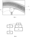
- FIG 1 there is shown a Slope Stability Lidar 10 that is viewing a scene 11 that may have regions which are stable and other regions which are moving.
- the scene 11 is part of the slope of an open cut mine 12, but as explained below the invention is not limited to this application.
- the Lidar 10 may be a commercially available device such as a Leica Scanstation P20 available from Leica Geosystems or it may be a proprietary device.
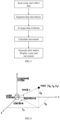
- the elements of the Lidar 10 are shown schematically in the block diagram of FIG 2 .
- the Lidar 10 is constructed from a pulsed laser 101, scanner 102, receiver 103, processor 104 and various output options 105.
- the Lidar produces a "point cloud" of a scene by scanning the laser in azimuth and elevation.
- the point cloud is commonly displayed as a colour-coded intensity or amplitude map that displays the amplitude (or intensity) of the reflected laser light for each azimuth, elevation and range point.
- the laser repetitively sends out pulses and detects each reflected pulse.
- the time between sending the pulse and receiving the reflection is used to calculate distance from the laser using time of flight.
- the combination of azimuth, elevation and distance is used by the processor to construct a three dimensional (3D) image of a scene around the Lidar.
- Scanning of the laser may be achieved by any appropriate technique but it has been found that a spinning or oscillating mirror is effective for providing the elevation scan and a rotating base is effective for the azimuth scan.
- the output 105 may be an image of the scene but the point data may also be accessed directly for further or alternate processing.
- Terrestrial Lidar scanners use all data that is collected to generate the scene. They produce a high quality image, which is to say that the range and direction measurements have high resolution, but a relatively long time is required to generate the image and a large data file is produced.
- the inventors have realized that the timescale to generate a data file and to process the data file to produce a scene using Lidar is too long to be useful for monitoring a region, such as a slope or a wall, for movement.
- the inventors have therefore developed a new processing approach that achieves useful movement data in a much shorter time and with much greater range precision than is conventionally available using Lidar.
- the inventors have also found that the precision of laser scanning is not sufficient for movement detection in many applications, particularly safety applications such as monitoring rock/slope movement in a mine.
- the laser measurement precision is affected by range, colour of the target, sensor settings and environment. It is not unusual to measure movement noise of up to +/- 8mm for a stationary target.
- the process developed by the inventors increases the precision significantly so that Lidar can be used for rock/slope movement detection.
- FIG 3 there is shown a flowchart summarizing the steps for producing movement data using Slope Stability Lidar.
- the point cloud data is collected in the usual manner but an averaging method is used to calculate a value for average amplitude (or intensity) at a precise range measured in a segment of the region.
- the size of the segment is selected as a suitable trade off against resolution to improve precision.
- a typical segment will have an extent of 0.5 degrees x 0.5 degrees and contain from several hundred to several thousand points from the point cloud.
- the selected segment is suitably circular but other shapes may also be selected such as a rectangle, triangle, hexagon or polygon.
- the averaging process may be a simple average of the amplitude (or intensity) and range of all points within the selected segment.
- the average may be a more complicated averaging process, for example by underweighting the values towards the periphery of the selected segment compared to the values towards the center of the segment.
- the segments may be contiguous or may overlap by a determined amount. In most cases it will not be appropriate to omit points by leaving a space between the selected segments.
- the Leica ScanStation P20 (mentioned above) produces high density and high resolution point cloud data that can be advantageously used to increase the range precision of the scanner by applying a spatial averaging algorithm which trades-off high angular resolution for range precision.
- the spatial averaging algorithm can be described in three steps:
- An optional fourth step is to display the data in a pixel that may be smaller than the averaged area.
- the pixel is most suitably square but could be hexagonal, circular or some other appropriate shape.
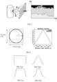
- the raw data exported from the laser scanner represents each point in the Cartesian coordinate system. This system splits the 3D world into three planes (x, y, and z) where the origin (0, 0, 0) is represented as the scanner origin, as depicted in FIG 4 .
- the coordinates are parameterized spherically to azimuth angle ⁇ , elevation angle ⁇ , and range r.
- Azimuth ⁇ tan ⁇ 1 y x
- Elevation ⁇ tan ⁇ 1 z x 2 + y 2
- Segmentation is the process of dividing the data into smaller but meaningful parts termed segments, as depicted in FIG 5 .
- the point cloud retrieved from the laser scanner is converted to a standard file format that contains a single header line representing the number of points in the cloud followed by x, y, z and intensity values for each point separated by a new line.
- An example is shown below: 418733
- the first line of this file is the number of points in the point cloud.
- the second line is read as an x position of 1.997177, a y position of -20.065475, a z position of -0.973618 and an intensity of 342. This is converted to range of 20.18, azimuth of -84.31 degrees and elevation of -13.71 degrees. It should be noted that the P20 generates intensity values in the range -2047 to +2048. These are routinely scaled to a range of 0 to 100.
- the data is then segmented into unique regular bins defined by equal azimuth and elevation angles.
- the segments may be saved into individual files for pixel point processing to help manage physical memory usage.
- the process involves first computing the centrepoint of each segment to be averaged.
- the centrepoint is chosen as the true halfway point in both azimuth and elevation.
- a linear weighted average is applied in terms of distance from the centrepoint in terms of spherical coordinates as depicted in FIG 6 .
- the process is especially advantageous as it smooths out any large deviations such as stray points that can be present due to edge effects or beam splitting.
- the invention is not limited to the specific linear weighting shown in FIG 6 .
- Other weighting functions such as those depicted in FIG 7 could also be used.
- the top hat of FIG 7(a) weights all points equally.
- the normal distribution of FIG 7(b) places greater weight on the points towards the centre of the segment.
- the averaging window of FIG 7(c) applies a linear weighing to minimise edge effects and FIG 7(d) also minimises edge effects but using a non-linear weighting.
- the segments may be contiguous as shown in FIG 8(a) .
- all points are used in the averaging process.
- An alternative arrangement is shown in FIG 8(b) in which some points are used in more than one segment.
- the segments are overlapping.
- the weight function can also be applied to the range direction of the voxels.
- FIG 9 shows the precision of measurements of range to a black card taken by a Leica Scanstation P20 at a range of 5m.
- the averaged measurement 120 at 5m is far more precise than the non-averaged measurement 121.
- the inventors have found that for stationary rough rock wall targets precision of +/-0.09mm per scan was achieved with this technique compared with as much as +/-17.2mm per scan when comparing unprocessed point cloud data.
- ideal laboratory conditions for moving targets the averaged data measured readings to an accuracy of ⁇ 0.05 mm as the movement occurred compared with ideal point cloud data of the target measuring movement with an accuracy of +/-8mm.
- an embodiment of the invention was used to monitor a slope in a pit that included moving and stationary regions within an area.
- the slope is shown in FIG 10 and the monitored region is shown by the black box.
- the Slope Stability Lidar collected data from the region and the data was segmented into 0.5 by 0.5 degree voxels and the amplitude and range was averaged using the weightings of FIG 6 and overlapping segments like FIG 8(b) .
- the movement (in millimetres) in each voxel is displayed in FIG 11 using the colour palette scale to the right.
- the X-axis spans an azimuth range of 90 voxels (45 degrees) and the Y-axis spans an elevation range of 25 voxels (12.5 degrees).
- FIG 12 shows the 3D photographic point cloud generated by the Leice Scanstation P20 with the movement scan of FIG 11 shown below using the same coordinate system. The movement depicted in FIG 12 compares well with movement data collected using the Slope Stability Radar described in WO2002/046790.
- a standalone SSL pack 130 is shown in FIG 13 .
- the standalone SSL 130 comprises a combined Lidar and camera unit 131 that is mounted on a gimbal scanner 132 that oscillates in azimuth and elevation.
- a user interface and output 133 is provided directly to the processor 134, which has an internal power supply (not visible).
- the SSL 130 may conveniently be mounted on a stable wall (although this is not essential) of an underground mine and configured to monitor a nearby wall or roof for movement, as shown in FIG 14 .
- Mounting points 140 may be conveniently located so that a rock mechanic 141 can move the standalone SSL 130 from place to place as needed.
- the SSL is deployed at the end of a boom to monitor a stope, as depicted in FIG 15 .
- a Lidar assembly 150 comprises a boom 151 and a tripod mount 152.
- the tripod mount 152 is positioned at the end of an access drive 153.
- a bore hole 154 is drilled from the access drive 153 into a stope cavity 155 and the Lidar & camera unit 156 is lowered on the boom 151 to monitor the top of the stope cavity 155 above the ore 157.
- the Lidar and camera unit 156 has the same elements as the standalone SSL 130. An alternate deployment could be from the gallery 158.
- FIG 16 shows an enlarged view of the SSL in the application of FIG 15 .
- the thickness of the roof of the stope is shown thinner than reality for easier description. It can be seen that the bore hole 154 is cased with rollers 163 to stabilise the boom 151 and remove movement.
- the tripod mount 152 is shown in more detail in FIG 17 including the user interface 171 for use by the worker 141.
- the user interface 170 and processor allows the worker 141 to control azimuth and elevation of the Lidar scan and to observe a local display.
- a communication module 171 provides an uplink to communicate with a mine control room. It also may provide a local alarm to give warning of dangerous movement.
- the Lidar unit 156 need not be located at the end of the boom 151 but could be located at the tripod mount 152 with the laser beam delivered through the boom 151 using suitable optics.
- This embodiment removes all sources of spark from the stope and is intrinsically safe. The same principal may be applied for other underground applications with any source of spark being located well away from potential danger and the laser beam being conveyed to the monitor site by optics, such as optical fibre.
- FIG 18 An effective manner of producing square pixels using the method described herein is shown in FIG 18 .
- the point cloud data is captured from a dome centred on the Lidar, it can be rolled out to a grid of azimuth and elevation as shown in FIG 18 .
- the size of each square of the grid in the example of FIG 18 is 0.5 degrees by 0.5 degrees.
- the weighting factors 181, 182 are applied to the data in the manner depicted in FIG 18 and described above to produce a square pixel.
- FIG 18 The processing shown in FIG 18 is applied to produce the display of FIG 19 .
- the display format is familiar to users because it is the same as the display presented for the SSR product mentioned earlier.
- FIG 19 shows a visual image of a monitored region with an amplitude map co-registered below.
- FIG 20 shows the same scene but with movement data rather than amplitude data.
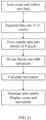
- FIG 21 An alternate spatial averaging process is depicted in FIG 21 .
- Raw data is acquired as described previously and converted to a spherical coordinate system.
- the data is segmented into voxels of a selected size; say 1o x 1o.
- the voxel is over-sampled by collecting data from the neighbouring voxels to produce a block of 9 voxels measuring 3o x 3o.
- the block is divided into 900 0.1o x 0.1o sub-voxels.
- the mean range for each sub-voxel is determined using a weighted average calculation as described previously.
- the mean range for each sub-voxel is compared with the mean range for that sub-voxel calculated from the previous scan.
- the median value for the 900 sub-voxels is determined and this value is displayed as the movement value for the selected 1o x 1o voxel.
- the process is repeated for each 1o x 1o voxel
- the median movement value may be determined from a subset of the 900 sub-voxels, for instance by applying a threshold.
- the threshold may be set to exclude any range change outlier. That is to say, if the range change exceeds a reasonable limit it is excluded. This will typically be some number of standard deviations from the mean value.
- an angle is determined between the plane of best fit and a line of sight (LOS) vector to the scanner from the centre of the voxel.
- the angle is measured against a threshold. If the angle is above the threshold the process of FIG 21 is followed. If the angle is low (grazing angle) the range value from the LOS vector is replace with a range value from the normal vector to the plane of best fit, and then the process of FIG 21 is followed.
- the plane of best fit could be extended to use more of the point cloud around the voxel. This would make the plane less sensitive to wall roughness.
- the behaviour of the rock surface is important to detect and measure.
- a rock surface that cracks or breaks up or erodes can give vital clues to impending collapse, while conversely, in the centre of a moving block of rock coherence may be high while the entire slab moves compared with the incoherent edges of the block that grind away and splinter as the rock slab moves.
- the coherence of a target may be affected by vegetation, passing people, machines or vehicles, or by water or other objects moving on the surface, meaning that a measure of coherence of the surface can at times be used as a data quality indicator.
- the Applicant has previously described the use of coherence with slope stability radar in their earlier international publication WO/2007/009175 , the content of which is incorporated herein by reference.
- a spatial coherence metric for each voxel generated by the SSL method can be calculated based on changes in the spatial distribution of the point cloud range measurements for each voxel and its surrounding neighbours between scans (or over time). Such a metric can be shown on a scale of 1 to 0, where 1 is 100% coherent and 0 is 0% coherent.
- the coherence metric describes how the small scale spatial character of the rock wall scattering surface changes between scans. In comparison, deformation describes a larger scale or voxel size change in the bulk range to the rock wall surface. Either range or amplitude distributions, or the combination of both, can be used to determine the coherence metric.
- the coherence metric can then be generated as an image for the area.
- raw data is acquired as described previously and converted to a spherical coordinate system.
- the data is segmented into voxels of a selected size; say 1o x 1o.
- the voxel is over-sampled by collecting data from the neighbouring voxels to produce a block of 9 voxels measuring 3o x 3o.
- the block is divided into 900 0.1o x 0.1o sub-voxels.
- the mean range and mean amplitude for each sub-voxel is determined using a weighted average calculation as described previously.
- the sub-voxel spatial distributions are compared with the previous scan to determine the coherence for the given voxel.
- the value is displayed as the coherence value for the selected 1o x 1o voxel typically on a scale of 1 to 0 where 1 is 100% coherent and 0 is 0% coherent.
- the process is repeated for each 1o x 1o voxel to generate a coherence image or map with a colour gradient applied to the spread of values.
- a Delta Coherence image or map can be generated from this coherence data if scanning continues over a longer time period, for example, three to tens-of-thousands of scans. To generate such an image or value the above process is repeated many times over many scans, and the lowest coherence metric (ie., minimum hold function) for each 1° x 1° voxel is displayed over the selected time period as the delta coherence value for that voxel.
- Coherence maps may be displayed in the form described in our earlier international application mentioned above.
- voxels of the specific size mentioned may be in the ranges mentioned earlier.
- the number of neighbouring voxels may also be varied. For instance, voxels may be circular or hexagonal and therefore have 6 near neighbours and 8 corner neighbours.
Landscapes
- Engineering & Computer Science (AREA)
- Physics & Mathematics (AREA)
- Electromagnetism (AREA)
- Computer Networks & Wireless Communication (AREA)
- General Physics & Mathematics (AREA)
- Radar, Positioning & Navigation (AREA)
- Remote Sensing (AREA)
- Mining & Mineral Resources (AREA)
- Life Sciences & Earth Sciences (AREA)
- General Life Sciences & Earth Sciences (AREA)
- Paleontology (AREA)
- Civil Engineering (AREA)
- General Engineering & Computer Science (AREA)
- Structural Engineering (AREA)
- Optical Radar Systems And Details Thereof (AREA)
- Pit Excavations, Shoring, Fill Or Stabilisation Of Slopes (AREA)
- Burglar Alarm Systems (AREA)
Description
- The present invention relates to a method and apparatus for monitoring slope deformation using laser ranging. The invention finds particular application in open cut and underground mining applications.
- The Applicant has previously described a Slope Monitoring System based on using interferometric radar measurements to detect movement of an observed slope. The technique is well described in our International Patent Application number
WO2002/046790 . In one important application the Slope Stability Radar (SSR) described inWO2002/046790 is used to monitor rock walls in an open cut mine to detect any dangerous movement that may lead to slope failure. - The Applicant's SSR devices have proven to be very effective and have enjoyed significant commercial success.
- In
WO2002/046790 reference is made to the use of laser EDM (Electronic Distance Measurement) as a tool that was used at that time to measure the dilation of cracks appearing on the crest or face of the rock slope. Most of the laser-based techniques monitor points or lines on a wall rather than an area of the wall face. This has meant that laser-based distance measurement systems have not been useful for deformation monitoring in mining applications, or similar situations. - For instance, document XP055375655: Hu Hui has published a detailed doctoral thesis from
- Aachen University, Germany titled, "Deformation monitoring and modelling based on LiDAR data for slope stability assessment". As recognised by Hui on page 17, "The challenge is how to efficiently analyse the LiDAR data and how to extract the valuable information (e.g. deformation signs) from huge amounts of data". Hui does not present a solution except to apply greater processing power or limit the scan to reduce the amount of data. In spite of the best efforts of Hui the sub-millimetre precision required for slope monitoring is not demonstrated.
- Reference may also be had to a useful review paper published online in 2010 and in Natural Hazards (2012) 61 :5-28 with the title "Use of LIDAR in landslide investigations: a review". The paper provides a useful discussion of LIDAR
- In the conclusion section the authors make a number of relevant points about the limitation of LIDAR in slope stability monitoring including, "In a few years, LIDAR sensors will probably be a standard tool for landslide analysis..... As the technique is also progressing, more accurate and precise ALS (airborne laser scanner) and TLS (terrestrial laser scanner) devices will appear, allowing for the generation of more accurate DEM (digital elevation map).... Nevertheless, the huge amount of data will remain a problem as the computers will need to be more powerful with increasing data acquisition capacity as it is already the case with mobile LIDAR systems that have an acquisition rate of up to 200 kHz. The real challenge is to develop new methods to better take benefit from HRDEM (high resolution digital elevation map). Indeed a lot of new information can be extracted from such DEM that we not yet contrived to do. Although great advances have been developed in geometrical aspects, most of the conceptual models remain tied to the past". These comments are still applicable today.
- In one form, although it need not be the only or indeed the broadest form, the invention resides in a Slope Stability Lidar according to claim 1.
- The alert may be audible, visual or tactile. A visual alert may suitably be displayed on the display.
- Suitably the processor of the Slope Stability Lidar may co-register the image of the area with a photograph or video of the area. The Slope Stability Lidar suitably comprises a camera that records the photograph or video.
- The laser is preferably a pulsed laser and the processor determines range to a point using a time of flight calculation.
- The scanner suitably scans the laser beam in azimuth using a rotating base and in elevation using a rotating mirror.
- The location of each point may be determined in Cartesian coordinates (x,y,z) or polar coordinates (r,θ,φ). Each block forming a voxel may be selected based on a specific voxel size, such as all range points within an azimuth by elevation of 0.5 degrees by 0.5 degrees. The voxel size may have an azimuth of from 0.1 degrees to 1.0 degrees. The elevation may be 0.1 degrees to 1.0 degrees. The voxel size may be any combination of azimuth by elevation from 0.1 degrees x 0.1 degrees to 1.0 degrees by 1.0 degrees. Some examples include 0.2 degrees by 0.3 degrees, 0.5 degrees by 0.4 degrees, or any other suitable size.
- The voxel size may also have range limits rather than averaging all ranges within an elevation by azimuth. Range limits may be applied to exclude ranges that have known artefacts, for example a road.
- In a further form the invention resides in a method according to claim 6.
- The display may be co-registered with a photographic or video image of the area.
- Further features and advantages of the present invention will become apparent from the following detailed description.
- To assist in understanding the invention and to enable a person skilled in the art to put the invention into practical effect, preferred embodiments of the invention will be described by way of example only with reference to the accompanying drawings, in which:
- FIG 1
- is a sketch of a Slope Stability Lidar in an open cut mine application;
- FIG 2
- is a block diagram of the components of a Slope Stability Lidar;
- FIG 3
- is a flowchart of the processing steps of a Slope Stability Lidar;
- FIG 4
- displays the process of spherical parameterization;
- FIG 5
- displays the process of segmentation;
- FIG 6
- displays one example of the process of point selection and weighting for pixel averaging;
- FIG 7
- depicts alternate point selection and weighting for pixel averaging;
- FIG 8
- shows alternate segmentation options;
- FIG 9
- demonstrates improved precision;
- FIG 10
- shows a monitored section of slope;
- FIG 11
- shows the monitoring data;
- FIG 12
- shows a comparison of the slope and the monitoring data in 3D with the top image showing the monitored area and the bottom image showing deformation;
- FIG 13
- shows another embodiment of a Slope Stability Lidar;
- FIG 14
- shows an application in an underground mine;
- FIG 15
- shows application in an underground stope;
- FIG 16
- is an enlarged view of a part of
FIG 15 ; - FIG 17
- is a close up view of the Slope Stability Lidar of
FIG 16 ; - FIG 18
- further explains the formation of a pixel;
- FIG 19
- shows a typical SSL display of amplitude co-registered with a visual image;
- FIG 20
- shows a typical SSL display of deformation co-registered with a visual image;
- FIG 21
- shows a typical flow chart depicting the steps of a method according to the invention; and
- FIG 22
- shows a typical flow chart depicting the steps of a method to deal with low grazing angle noise according to the invention.
- Embodiments of the present invention reside primarily in a Slope Stability Lidar apparatus that utilizes a laser to monitor the movement of a slope, wall or other region which may be subject to movement. Accordingly, the elements of the device have been illustrated in concise schematic form in the drawings, showing only those specific details that are necessary for understanding the embodiments of the present invention, but so as not to obscure the disclosure with excessive detail that will be readily apparent to those of ordinary skill in the art having the benefit of the present description.
- In this specification, adjectives such as first and second, left and right, and the like may be used solely to distinguish one element or action from another element or action without necessarily requiring or implying any actual such relationship or order. Words such as "comprises" or "includes" are intended to define a non-exclusive inclusion, such that a process, method, article, or apparatus that comprises a list of elements does not include only those elements but may include other elements not expressly listed, including elements that are inherent to such a process, method, article, or apparatus.
- Referring to
FIG 1 there is shown aSlope Stability Lidar 10 that is viewing ascene 11 that may have regions which are stable and other regions which are moving. In the embodiment ofFIG 1 thescene 11 is part of the slope of anopen cut mine 12, but as explained below the invention is not limited to this application. TheLidar 10 may be a commercially available device such as a Leica Scanstation P20 available from Leica Geosystems or it may be a proprietary device. The elements of theLidar 10 are shown schematically in the block diagram ofFIG 2 . TheLidar 10 is constructed from apulsed laser 101,scanner 102,receiver 103,processor 104 andvarious output options 105. - The Lidar produces a "point cloud" of a scene by scanning the laser in azimuth and elevation. The point cloud is commonly displayed as a colour-coded intensity or amplitude map that displays the amplitude (or intensity) of the reflected laser light for each azimuth, elevation and range point. The laser repetitively sends out pulses and detects each reflected pulse. The time between sending the pulse and receiving the reflection is used to calculate distance from the laser using time of flight. The combination of azimuth, elevation and distance is used by the processor to construct a three dimensional (3D) image of a scene around the Lidar. Although it is possible to generate the scene in a complete dome around the Lidar it is the case in most applications that only a small section of the dome is of interest.
- Scanning of the laser may be achieved by any appropriate technique but it has been found that a spinning or oscillating mirror is effective for providing the elevation scan and a rotating base is effective for the azimuth scan.
- The
output 105 may be an image of the scene but the point data may also be accessed directly for further or alternate processing. Terrestrial Lidar scanners use all data that is collected to generate the scene. They produce a high quality image, which is to say that the range and direction measurements have high resolution, but a relatively long time is required to generate the image and a large data file is produced. The inventors have realized that the timescale to generate a data file and to process the data file to produce a scene using Lidar is too long to be useful for monitoring a region, such as a slope or a wall, for movement. The inventors have therefore developed a new processing approach that achieves useful movement data in a much shorter time and with much greater range precision than is conventionally available using Lidar. - The inventors have also found that the precision of laser scanning is not sufficient for movement detection in many applications, particularly safety applications such as monitoring rock/slope movement in a mine. The laser measurement precision is affected by range, colour of the target, sensor settings and environment. It is not unusual to measure movement noise of up to +/- 8mm for a stationary target. The process developed by the inventors increases the precision significantly so that Lidar can be used for rock/slope movement detection.
- Referring to
FIG 3 , there is shown a flowchart summarizing the steps for producing movement data using Slope Stability Lidar. The point cloud data is collected in the usual manner but an averaging method is used to calculate a value for average amplitude (or intensity) at a precise range measured in a segment of the region. The size of the segment is selected as a suitable trade off against resolution to improve precision. A typical segment will have an extent of 0.5 degrees x 0.5 degrees and contain from several hundred to several thousand points from the point cloud. The selected segment is suitably circular but other shapes may also be selected such as a rectangle, triangle, hexagon or polygon. - The averaging process may be a simple average of the amplitude (or intensity) and range of all points within the selected segment. Alternatively the average may be a more complicated averaging process, for example by underweighting the values towards the periphery of the selected segment compared to the values towards the center of the segment.
- The segments may be contiguous or may overlap by a determined amount. In most cases it will not be appropriate to omit points by leaving a space between the selected segments.
- By way of example, the Leica ScanStation P20 (mentioned above) produces high density and high resolution point cloud data that can be advantageously used to increase the range precision of the scanner by applying a spatial averaging algorithm which trades-off high angular resolution for range precision. The spatial averaging algorithm can be described in three steps:
- 1. Spherical parameterization of scanner coordinates;
- 2. Segmentation of data evenly in the azimuth and elevation direction (with coarse range bins);
- 3. Applying a weighted average for each segment with respect to the true centre value.
- An optional fourth step is to display the data in a pixel that may be smaller than the averaged area. The pixel is most suitably square but could be hexagonal, circular or some other appropriate shape.
- The raw data exported from the laser scanner represents each point in the Cartesian coordinate system. This system splits the 3D world into three planes (x, y, and z) where the origin (0, 0, 0) is represented as the scanner origin, as depicted in
FIG 4 . - The coordinates are parameterized spherically to azimuth angle θ, elevation angle φ, and range r. The transformation is given by:


- Segmentation is the process of dividing the data into smaller but meaningful parts termed segments, as depicted in
FIG 5 . The point cloud retrieved from the laser scanner is converted to a standard file format that contains a single header line representing the number of points in the cloud followed by x, y, z and intensity values for each point separated by a new line. An example is shown below:
418733 - 1.997177 -20.065475 -0.973618 342
- 1.993637 -20.062546 -0.970444 339
- 1.989090 -20.016830 -1.094131 308
- 1.998581 -20.017014 -1.100418 362
- The first line of this file is the number of points in the point cloud. The second line is read as an x position of 1.997177, a y position of -20.065475, a z position of -0.973618 and an intensity of 342. This is converted to range of 20.18, azimuth of -84.31 degrees and elevation of -13.71 degrees. It should be noted that the P20 generates intensity values in the range -2047 to +2048. These are routinely scaled to a range of 0 to 100.
- The data is then segmented into unique regular bins defined by equal azimuth and elevation angles. The segments may be saved into individual files for pixel point processing to help manage physical memory usage.
- A weighted average is expressed mathematically as:

x is the computed mean, wn is the weight for data point n, and xn is the value of data point n. - The process involves first computing the centrepoint of each segment to be averaged. The centrepoint is chosen as the true halfway point in both azimuth and elevation. Then a linear weighted average is applied in terms of distance from the centrepoint in terms of spherical coordinates as depicted in
FIG 6 . - In the case of the point cloud generated by the laser scanner, the process is especially advantageous as it smooths out any large deviations such as stray points that can be present due to edge effects or beam splitting.
- The invention is not limited to the specific linear weighting shown in
FIG 6 . Other weighting functions such as those depicted inFIG 7 could also be used. The top hat ofFIG 7(a) weights all points equally. The normal distribution ofFIG 7(b) places greater weight on the points towards the centre of the segment. The averaging window ofFIG 7(c) applies a linear weighing to minimise edge effects andFIG 7(d) also minimises edge effects but using a non-linear weighting. - As mentioned above, the segments may be contiguous as shown in
FIG 8(a) . In this embodiment all points are used in the averaging process. An alternative arrangement is shown inFIG 8(b) in which some points are used in more than one segment. The segments are overlapping. The weight function can also be applied to the range direction of the voxels. - The benefit of the process described above is clearly demonstrated in
FIG 9. FIG 9 shows the precision of measurements of range to a black card taken by a Leica Scanstation P20 at a range of 5m. As can be seen, the averagedmeasurement 120 at 5m is far more precise than thenon-averaged measurement 121. In various tests the inventors have found that for stationary rough rock wall targets precision of +/-0.09mm per scan was achieved with this technique compared with as much as +/-17.2mm per scan when comparing unprocessed point cloud data. In ideal laboratory conditions for moving targets the averaged data measured readings to an accuracy of ±0.05 mm as the movement occurred compared with ideal point cloud data of the target measuring movement with an accuracy of +/-8mm. - By way of example, an embodiment of the invention was used to monitor a slope in a pit that included moving and stationary regions within an area. The slope is shown in
FIG 10 and the monitored region is shown by the black box. The Slope Stability Lidar collected data from the region and the data was segmented into 0.5 by 0.5 degree voxels and the amplitude and range was averaged using the weightings ofFIG 6 and overlapping segments likeFIG 8(b) . The movement (in millimetres) in each voxel is displayed inFIG 11 using the colour palette scale to the right. The X-axis spans an azimuth range of 90 voxels (45 degrees) and the Y-axis spans an elevation range of 25 voxels (12.5 degrees). Movement towards the scanner is shown using the red end of the spectrum and movement away from the scanner is depicted using the blue end of the spectrum. Voxels with little or no movement are white or pale.FIG 12 shows the 3D photographic point cloud generated by the Leice Scanstation P20 with the movement scan ofFIG 11 shown below using the same coordinate system. The movement depicted inFIG 12 compares well with movement data collected using the Slope Stability Radar described inWO2002/046790. - The invention is not limited to use in open pits. Due to the compact nature of the Slope Stability Lidar and the intrinsic safety it can be used in underground mines. A
standalone SSL pack 130 is shown inFIG 13 . Thestandalone SSL 130 comprises a combined Lidar andcamera unit 131 that is mounted on agimbal scanner 132 that oscillates in azimuth and elevation. A user interface andoutput 133 is provided directly to theprocessor 134, which has an internal power supply (not visible). TheSSL 130 may conveniently be mounted on a stable wall (although this is not essential) of an underground mine and configured to monitor a nearby wall or roof for movement, as shown inFIG 14 . Mountingpoints 140 may be conveniently located so that arock mechanic 141 can move thestandalone SSL 130 from place to place as needed. - In another embodiment the SSL is deployed at the end of a boom to monitor a stope, as depicted in
FIG 15 . ALidar assembly 150 comprises aboom 151 and atripod mount 152. Thetripod mount 152 is positioned at the end of anaccess drive 153. Abore hole 154 is drilled from the access drive 153 into astope cavity 155 and the Lidar &camera unit 156 is lowered on theboom 151 to monitor the top of thestope cavity 155 above theore 157. The Lidar andcamera unit 156 has the same elements as thestandalone SSL 130. An alternate deployment could be from thegallery 158. -
FIG 16 shows an enlarged view of the SSL in the application ofFIG 15 . The thickness of the roof of the stope is shown thinner than reality for easier description. It can be seen that thebore hole 154 is cased withrollers 163 to stabilise theboom 151 and remove movement. - The
tripod mount 152 is shown in more detail inFIG 17 including theuser interface 171 for use by theworker 141. Theuser interface 170 and processor allows theworker 141 to control azimuth and elevation of the Lidar scan and to observe a local display. Acommunication module 171 provides an uplink to communicate with a mine control room. It also may provide a local alarm to give warning of dangerous movement. - The
Lidar unit 156 need not be located at the end of theboom 151 but could be located at thetripod mount 152 with the laser beam delivered through theboom 151 using suitable optics. This embodiment removes all sources of spark from the stope and is intrinsically safe. The same principal may be applied for other underground applications with any source of spark being located well away from potential danger and the laser beam being conveyed to the monitor site by optics, such as optical fibre. - Although various pixel shapes are disclosed above, the preferred pixel shape is square. An effective manner of producing square pixels using the method described herein is shown in
FIG 18 . Although the point cloud data is captured from a dome centred on the Lidar, it can be rolled out to a grid of azimuth and elevation as shown inFIG 18 . The size of each square of the grid in the example ofFIG 18 is 0.5 degrees by 0.5 degrees. The weighting factors 181, 182 are applied to the data in the manner depicted inFIG 18 and described above to produce a square pixel. - The processing shown in
FIG 18 is applied to produce the display ofFIG 19 . The display format is familiar to users because it is the same as the display presented for the SSR product mentioned earlier.FIG 19 shows a visual image of a monitored region with an amplitude map co-registered below.FIG 20 shows the same scene but with movement data rather than amplitude data. - An alternate spatial averaging process is depicted in
FIG 21 . Raw data is acquired as described previously and converted to a spherical coordinate system. The data is segmented into voxels of a selected size; say 1º x 1º. The voxel is over-sampled by collecting data from the neighbouring voxels to produce a block of 9 voxels measuring 3º x 3º. The block is divided into 900 0.1º x 0.1º sub-voxels. The mean range for each sub-voxel is determined using a weighted average calculation as described previously. The mean range for each sub-voxel is compared with the mean range for that sub-voxel calculated from the previous scan. The median value for the 900 sub-voxels is determined and this value is displayed as the movement value for the selected 1º x 1º voxel. The process is repeated for each 1º x 1º voxel to generate a movement map. - As an optional variation the median movement value may be determined from a subset of the 900 sub-voxels, for instance by applying a threshold. The threshold may be set to exclude any range change outlier. That is to say, if the range change exceeds a reasonable limit it is excluded. This will typically be some number of standard deviations from the mean value.
- For regions of low grazing angle between the area being monitored and the Slope Stability Lidar, a small Lidar angular beam pointing error can result in a large change in range value. Also, low grazing angles provide less back scatter and therefore lower signal to noise ratio, which means higher error in the range measurements. This can lead to large errors in deformation monitoring. To deal with this error a method has been developed as shown in
FIG 22 . Raw data is acquired and converted to a spherical coordinate system. The data is segmented into voxels of a selected size; say 1º x 1º. The next step is to describe a plane of best fit for the point cloud data inside each voxel. Then an angle is determined between the plane of best fit and a line of sight (LOS) vector to the scanner from the centre of the voxel. The angle is measured against a threshold. If the angle is above the threshold the process ofFIG 21 is followed. If the angle is low (grazing angle) the range value from the LOS vector is replace with a range value from the normal vector to the plane of best fit, and then the process ofFIG 21 is followed. The plane of best fit could be extended to use more of the point cloud around the voxel. This would make the plane less sensitive to wall roughness. - In the domain of geotechnical engineering in a mining context, the behaviour of the rock surface (otherwise known as the coherence of the surface) is important to detect and measure. A rock surface that cracks or breaks up or erodes can give vital clues to impending collapse, while conversely, in the centre of a moving block of rock coherence may be high while the entire slab moves compared with the incoherent edges of the block that grind away and splinter as the rock slab moves. At other times the coherence of a target may be affected by vegetation, passing people, machines or vehicles, or by water or other objects moving on the surface, meaning that a measure of coherence of the surface can at times be used as a data quality indicator. The Applicant has previously described the use of coherence with slope stability radar in their earlier international publication
WO/2007/009175 , the content of which is incorporated herein by reference. - The inventors have determined that a spatial coherence metric for each voxel generated by the SSL method can be calculated based on changes in the spatial distribution of the point cloud range measurements for each voxel and its surrounding neighbours between scans (or over time). Such a metric can be shown on a scale of 1 to 0, where 1 is 100% coherent and 0 is 0% coherent. The coherence metric describes how the small scale spatial character of the rock wall scattering surface changes between scans. In comparison, deformation describes a larger scale or voxel size change in the bulk range to the rock wall surface. Either range or amplitude distributions, or the combination of both, can be used to determine the coherence metric. The coherence metric can then be generated as an image for the area.
- The inventors have found for this geotechnical application there is generally too much noise in raw Lidar point cloud data for a useful coherence metric and some level of point cloud averaging is required.
- In one embodiment of the invention, raw data is acquired as described previously and converted to a spherical coordinate system. The data is segmented into voxels of a selected size; say 1º x 1º. The voxel is over-sampled by collecting data from the neighbouring voxels to produce a block of 9 voxels measuring 3º x 3º. The block is divided into 900 0.1º x 0.1º sub-voxels. The mean range and mean amplitude for each sub-voxel is determined using a weighted average calculation as described previously. The sub-voxel spatial distributions are compared with the previous scan to determine the coherence for the given voxel. The value is displayed as the coherence value for the selected 1º x 1º voxel typically on a scale of 1 to 0 where 1 is 100% coherent and 0 is 0% coherent. The process is repeated for each 1º x 1º voxel to generate a coherence image or map with a colour gradient applied to the spread of values.
- A Delta Coherence image or map can be generated from this coherence data if scanning continues over a longer time period, for example, three to tens-of-thousands of scans. To generate such an image or value the above process is repeated many times over many scans, and the lowest coherence metric (ie., minimum hold function) for each 1° x 1° voxel is displayed over the selected time period as the delta coherence value for that voxel. Coherence maps may be displayed in the form described in our earlier international application mentioned above.
- The above example is purely for the purpose of explanation. The invention is not limited to voxels of the specific size mentioned but may be in the ranges mentioned earlier. The number of neighbouring voxels may also be varied. For instance, voxels may be circular or hexagonal and therefore have 6 near neighbours and 8 corner neighbours.
- The above description of various embodiments of the present invention is provided for purposes of description to one of ordinary skill in the related art. It is not intended to be exhaustive or to limit the invention to a single disclosed embodiment. As mentioned above, numerous alternatives and variations to the present invention will be apparent to those skilled in the art of the above teaching. Accordingly, while some alternative embodiments have been discussed specifically, other embodiments will be apparent or relatively easily developed by those of ordinary skill in the art. Accordingly, this invention is intended to embrace all alternatives, modifications and variations of the present invention that have been discussed herein, and other embodiments that fall within the spirit and scope of the above described invention.
Claims (11)
- A Slope Stability Lidar comprising:a laser producing a beam of optical radiation;a scanner that directs the beam of optical radiation into an area on a point by point basis, each point having an elevation and azimuth with respect to the laser;a detector that receives reflected optical radiation from each point; anda processor programmed to:
acquire data from the detector and process the data to compile direction data, range data and amplitude data for each point;characterised in that the processor is programmed tosegment the acquired data into blocks of data defining a voxel, with each block forming a voxel being selected based on a specific voxel size, such that all range points are within an azimuth by elevation both from of 0.1 degrees to 1.0 degrees, the voxel size having range limits like to exclude ranges of known artefacts;average the acquired range data within the voxel to produce a precise voxel range value for each voxel;average the acquired amplitude data to produce an average amplitude value for each voxel, wherein the average amplitude value for each voxel is used by the processor to generate a display of an image of the area; compare voxel range values over time to identify movement; and generate an alert if movement exceeds a threshold, wherein the processor displays the identified movement on the image of the area. - The Slope Stability Lidar of claim 1 wherein the laser is a pulsed laser and the processor determines range to a point using a time of flight calculation.
- The Slope Stability Lidar of claim 1 wherein each block of data defining a voxel size is segmented by range.
- The Slope Stability Lidar of claim 1 wherein the processor co-registers the image of the area with a photograph or video of the area.
- The Slope Stability Lidar of claim 1 wherein the processor is further programmed to calculate a coherence metric for each voxel.
- A method of monitoring slope movement including the steps of:directing a beam of optical radiation into an area;scanning the beam of optical radiation in elevation and azimuth so as to cover the area on a point by point basis;detecting radiation reflected from each point;acquiring data from the detector and processing the data to compile direction data, range data and amplitude data for each point;characterised by segmenting the acquired data into blocks of data defining a voxel, with each block forming a voxel being selected based on a specific voxel size, such that all range points are within an aziumuth by elevation both from 0.1 degrees to 1.0 degree, the voxel size having range limits like to exclude ranges of known artefacts;averaging the acquired range data within the voxel to produce a precise range value;averaging the acquired amplitude data to produce an average amplitude value for each voxel, wherein the average amplitude value for each voxel is used in a further step of the method to generate a display of an image of the area, wherein the identified movement is displayed on the image of the area;comparing voxel range values over time to identify movement; andgenerating an alert if movement exceeds a threshold.
- The method of claim 6 wherein the step of averaging involves a weighted average and the weighting function is selected from: top hat; normal; linear edge minimisation; non-linear edge minimisation.
- The method of claim 6 wherein the step of segmenting the acquired data involves using data from some points in more than one block.
- The method of claim 6 further including the steps of:over-sampling a selected voxel by collecting data from neighbouring voxels;dividing the selected voxel and neighbouring voxels into sub-voxels;determining a mean range for each sub-voxel using a weighted average calculation;comparing a mean range for each sub-voxel to a mean range for that sub-voxel calculated from a previous scan;determining a median value for all sub-voxels and displaying the median value as the movement value for the selected voxel.
- The method of claim 6 further including the step of co-registering the display with a photographic or video image of the area.
- The method of claim 6 further including the step of calculating a coherence metric for each voxel.
Applications Claiming Priority (2)
| Application Number | Priority Date | Filing Date | Title |
|---|---|---|---|
| AU2015904141A AU2015904141A0 (en) | 2015-10-12 | Slope stability lidar | |
| PCT/AU2016/050953 WO2017063033A1 (en) | 2015-10-12 | 2016-10-12 | Slope stability lidar |
Publications (4)
| Publication Number | Publication Date |
|---|---|
| EP3362816A1 EP3362816A1 (en) | 2018-08-22 |
| EP3362816A4 EP3362816A4 (en) | 2019-05-15 |
| EP3362816B1 EP3362816B1 (en) | 2022-04-06 |
| EP3362816B2 true EP3362816B2 (en) | 2025-01-22 |
Family
ID=58516891
Family Applications (1)
| Application Number | Title | Priority Date | Filing Date |
|---|---|---|---|
| EP16854637.2A Active EP3362816B2 (en) | 2015-10-12 | 2016-10-12 | Slope stability lidar |
Country Status (8)
| Country | Link |
|---|---|
| US (1) | US11422255B2 (en) |
| EP (1) | EP3362816B2 (en) |
| JP (1) | JP7076372B2 (en) |
| AU (1) | AU2016340027B2 (en) |
| CA (1) | CA3000740C (en) |
| CL (1) | CL2018000917A1 (en) |
| WO (1) | WO2017063033A1 (en) |
| ZA (1) | ZA201802211B (en) |
Families Citing this family (22)
| Publication number | Priority date | Publication date | Assignee | Title |
|---|---|---|---|---|
| EP3315907B1 (en) * | 2016-10-27 | 2025-03-26 | Leica Geosystems AG | Verfahren zur visuellen darstellung von scandaten |
| AU2017221839B2 (en) | 2017-08-31 | 2023-11-02 | Groundprobe Pty Ltd | Lidar hinged mount |
| US11488296B2 (en) | 2017-11-28 | 2022-11-01 | Groundprobe Pty Ltd | Slope stability visualisation |
| AU2019319766B2 (en) * | 2018-08-07 | 2024-09-19 | Groundprobe Pty Ltd | Wall visualisation from virtual point of view |
| CN109763812B (en) * | 2018-12-10 | 2021-12-14 | 青岛海洋地质研究所 | Quantitative analysis method for mechanical stability of hydrate mining based on Mohr-Coulomb theory |
| CN110409369B (en) * | 2019-05-29 | 2021-06-04 | 水电水利规划设计总院 | Digital Construction and Quality Control Method of Slope Excavation |
| CN110596715B (en) * | 2019-09-20 | 2021-07-06 | 中国有色金属长沙勘察设计研究院有限公司 | A waterline intelligent identification system and positioning method |
| CN111046884B (en) * | 2019-12-09 | 2022-05-13 | 太原理工大学 | A method for extracting slope geological hazards based on multi-feature-assisted watershed algorithm |
| CN110965593B (en) * | 2019-12-24 | 2021-06-25 | 河南拓朴工程咨询有限公司 | Foundation pit deformation real-time monitoring system |
| WO2022040737A1 (en) | 2020-08-25 | 2022-03-03 | Groundprobe Pty Ltd | Slope failure monitoring system |
| KR102460825B1 (en) * | 2020-08-31 | 2022-10-31 | 네이버랩스 주식회사 | Method and system for localization |
| CN112731440B (en) * | 2020-12-25 | 2023-10-13 | 中国铁道科学研究院集团有限公司 | High-speed railway slope deformation detection method and device |
| JP7613973B2 (en) * | 2021-03-23 | 2025-01-15 | 株式会社トプコン | Surveying System |
| CN113449254B (en) * | 2021-06-09 | 2023-09-01 | 华设设计集团股份有限公司 | Method for analyzing monitoring stability of any net-type deformation and method for determining position of monitoring point |
| CN113390359B (en) * | 2021-06-15 | 2022-12-06 | 董世勇 | High-cutting slope deformation monitoring device |
| CN113920134B (en) * | 2021-09-27 | 2022-06-07 | 山东大学 | A method and system for segmentation of slope ground point cloud based on multi-line lidar |
| US12084961B2 (en) * | 2021-11-01 | 2024-09-10 | Saudi Arabian Oil Company | System and method for mapping a borehole using lidar |
| CN114942422A (en) * | 2022-03-31 | 2022-08-26 | 国网福建省电力有限公司经济技术研究院 | Laser radar-based slope deformation early warning system and method |
| CN115142393A (en) * | 2022-08-10 | 2022-10-04 | 安徽远信工程项目管理有限公司 | Foundation protection monitoring method based on safety engineering management |
| CN115451805A (en) * | 2022-09-13 | 2022-12-09 | 兰州石化职业技术大学 | A system and method for monitoring slope deformation of mountain roads |
| CN116125490B (en) * | 2023-02-03 | 2023-07-04 | 中国科学院精密测量科学与技术创新研究院 | TLS multi-objective optimization site selection method for landslide mass deformation field time sequence monitoring |
| CN117392569B (en) * | 2023-11-06 | 2024-11-05 | 上海勘测设计研究院有限公司 | Airborne Lidar point cloud ground point extraction method integrating DOM image and three-dimensional live-action model |
Citations (1)
| Publication number | Priority date | Publication date | Assignee | Title |
|---|---|---|---|---|
| US20130051655A1 (en) † | 2011-08-29 | 2013-02-28 | Raytheon Company | Noise Reduction in Light Detection and Ranging Based Imaging |
Family Cites Families (27)
| Publication number | Priority date | Publication date | Assignee | Title |
|---|---|---|---|---|
| US5745422A (en) | 1996-11-12 | 1998-04-28 | International Business Machines Corporation | Cross-coupled bitline segments for generalized data propagation |
| GB2419759B (en) | 2003-07-11 | 2007-02-14 | Omnicom Engineering Ltd | A system of surveying and measurement |
| BRPI0612902A2 (en) | 2005-07-18 | 2010-12-07 | Groundprobe Pty Ltd | interferometric signal processing |
| JP4129879B2 (en) * | 2005-07-25 | 2008-08-06 | 株式会社エヌ・ティ・ティ・データ | Image analysis apparatus, image analysis method, and program |
| US7864175B2 (en) | 2006-03-09 | 2011-01-04 | Ambercore Software Inc | Fast gridding of irregular data |
| WO2009067680A1 (en) * | 2007-11-23 | 2009-05-28 | Mercury Computer Systems, Inc. | Automatic image segmentation methods and apparartus |
| US20100053593A1 (en) * | 2008-08-26 | 2010-03-04 | Honeywell International Inc. | Apparatus, systems, and methods for rotating a lidar device to map objects in an environment in three dimensions |
| US20100204964A1 (en) * | 2009-02-09 | 2010-08-12 | Utah State University | Lidar-assisted multi-image matching for 3-d model and sensor pose refinement |
| JP4545219B1 (en) * | 2009-05-18 | 2010-09-15 | 国際航業株式会社 | Analysis method of topographic change using topographic image and program thereof |
| US20110149268A1 (en) * | 2009-12-17 | 2011-06-23 | Marchant Alan B | Dynamic 3d wind mapping system and method |
| KR101009657B1 (en) * | 2010-08-23 | 2011-01-19 | 박혁진 | Stochastic Rock Slope Stability Analysis Using Ground Lidar |
| AU2012211028B2 (en) * | 2011-01-28 | 2015-01-22 | Groundprobe Pty Ltd | Slope stability alarm |
| CN103403568B (en) * | 2011-03-01 | 2016-06-29 | 皇家飞利浦有限公司 | Determination of Classification of Magnetic Resonance Imaging Pulse Sequence Protocols |
| JP5711039B2 (en) * | 2011-04-27 | 2015-04-30 | 株式会社トプコン | 3D point cloud position data processing apparatus, 3D point cloud position data processing method, 3D point cloud position data processing system, and program |
| US9041589B2 (en) * | 2012-04-04 | 2015-05-26 | Caterpillar Inc. | Systems and methods for determining a radar device coverage region |
| US20140267250A1 (en) | 2013-03-15 | 2014-09-18 | Intermap Technologies, Inc. | Method and apparatus for digital elevation model systematic error correction and fusion |
| US9523772B2 (en) * | 2013-06-14 | 2016-12-20 | Microsoft Technology Licensing, Llc | Object removal using lidar-based classification |
| US9110163B2 (en) * | 2013-06-14 | 2015-08-18 | Microsoft Technology Licensing, Llc | Lidar-based classification of object movement |
| US9613440B2 (en) * | 2014-02-12 | 2017-04-04 | General Electric Company | Digital breast Tomosynthesis reconstruction using adaptive voxel grid |
| EP2998700B2 (en) * | 2014-09-18 | 2022-12-21 | Hexagon Technology Center GmbH | Electro-optical distance gauge and distance measuring method |
| US10387018B2 (en) * | 2014-12-18 | 2019-08-20 | Groundprobe Pty Ltd | Geo-positioning |
| US10194829B2 (en) * | 2015-07-07 | 2019-02-05 | Q Bio, Inc. | Fast scanning based on magnetic resonance history |
| DK3264135T3 (en) * | 2016-06-28 | 2021-07-12 | Leica Geosystems Ag | LONG-TERM LIDAR SYSTEM AND PROCEDURE FOR COMPENSATION FOR THE EFFECT OF SCANNER MOVEMENT |
| US10473775B2 (en) * | 2017-03-20 | 2019-11-12 | David Slemp | Frequency modulated continuous wave antenna system |
| US10444759B2 (en) * | 2017-06-14 | 2019-10-15 | Zoox, Inc. | Voxel based ground plane estimation and object segmentation |
| US11157527B2 (en) * | 2018-02-20 | 2021-10-26 | Zoox, Inc. | Creating clean maps including semantic information |
| US10649459B2 (en) * | 2018-04-26 | 2020-05-12 | Zoox, Inc. | Data segmentation using masks |
-
2016
- 2016-10-12 JP JP2018537696A patent/JP7076372B2/en active Active
- 2016-10-12 WO PCT/AU2016/050953 patent/WO2017063033A1/en not_active Ceased
- 2016-10-12 EP EP16854637.2A patent/EP3362816B2/en active Active
- 2016-10-12 US US15/767,073 patent/US11422255B2/en active Active
- 2016-10-12 CA CA3000740A patent/CA3000740C/en active Active
- 2016-10-12 AU AU2016340027A patent/AU2016340027B2/en active Active
-
2018
- 2018-04-04 ZA ZA2018/02211A patent/ZA201802211B/en unknown
- 2018-04-10 CL CL2018000917A patent/CL2018000917A1/en unknown
Patent Citations (1)
| Publication number | Priority date | Publication date | Assignee | Title |
|---|---|---|---|---|
| US20130051655A1 (en) † | 2011-08-29 | 2013-02-28 | Raytheon Company | Noise Reduction in Light Detection and Ranging Based Imaging |
Non-Patent Citations (12)
| Title |
|---|
| A. Abellan et al., „Detection of millimetric deformation using a terrestrial laser Scanner: experiment and application to a rockfall event", Nat. Hazards Earth Syst. Sci.,9,pp.365-372,2009, veröffentlicht am 17.03.2009 † |
| Ausdruck aus dem Internet-Archiv („Wayback Machine", archive.org) zum Stand der Website www.riegl.com am 14. September 2013 betreffend die Software „Riscan PRO" † |
| Auszug aus dem Online-Lexikon Wikipedia zum Eintrag „Laserscanning", veröffentlicht am 1. März 2015 † |
| Auszug aus dem Tagungsband „12. Geokinematischer Tag des Institutes für Markscheidewesen und Geodäsie am 5. und 6. Mai 2011 in Freiberg" betreffend den Vortrag „Automatisiertes Deformationsmonitoring an fortschreitenden Tagebauböschungen der Mitteldeutschen Braunkohlen GmbH (MIBRAG) mit RIEGL Laserscan-Technologie", veröffentlicht im Jahre 2011 † |
| Eidesstattliche Erklärung von Herrn Dr. Martin Pfennigbauer zu den Anlagen 4 und 5 † |
| Eidesstattliche Erklärung von Herrn Thomas Gaisecker zu den Anlagen 1 und 2 † |
| Foliensatz Vortrag "Einsatz des VZ 4000 im Vorschnitt 1 des Tagebaues Welzow-Süd", Markscheiderisches Kolloquium 2014 – VE Mining, Syperion GmbH & Co. KG † |
| Handbuch Riscan PRO, Operating & Processing Software for RIEGL 3D Laser Scanners, Version 1.7.9, veröffentlicht im September 2013 † |
| J. Theule et al-, "SEDIMENT BUDGET MONITORING OF A DEBRISFLOW TORRENT (FRENCH PREALPS)", Italian Journal of Engineering Geology and Environment - Book, 2011, pp.779-786,veröffentlicht am 30. November 2011 (Veröffentlichungstag entnommen von https://doi.org/10.4408/IJEGE.2011-03.B085) † |
| M. Jaboyedoff et al., „Use of LIDAR in landslide investigations: a review", Nat. Hazards, 61, pp. 5 - 28, 2012,veröffentlicht am 19. Oktober 2010 † |
| Präsentationsfolien des oben genannten Vortrags, präsentiert am 5. Mai 2011 † |
| Vertriebsprospekt („Data Sheet") Software Riscan PRO, veröffentlicht am 22. September 2010 † |
Also Published As
| Publication number | Publication date |
|---|---|
| CL2018000917A1 (en) | 2018-08-31 |
| US11422255B2 (en) | 2022-08-23 |
| EP3362816A4 (en) | 2019-05-15 |
| WO2017063033A1 (en) | 2017-04-20 |
| CA3000740A1 (en) | 2017-04-20 |
| EP3362816B1 (en) | 2022-04-06 |
| AU2016340027B2 (en) | 2020-04-16 |
| AU2016340027A1 (en) | 2018-04-19 |
| ZA201802211B (en) | 2018-12-19 |
| JP2018531402A (en) | 2018-10-25 |
| CA3000740C (en) | 2022-09-06 |
| EP3362816A1 (en) | 2018-08-22 |
| JP7076372B2 (en) | 2022-05-27 |
| US20180299551A1 (en) | 2018-10-18 |
Similar Documents
| Publication | Publication Date | Title |
|---|---|---|
| EP3362816B2 (en) | Slope stability lidar | |
| JP2018531402A6 (en) | Slope stability rider | |
| Yoon et al. | Feature extraction of a concrete tunnel liner from 3D laser scanning data | |
| Pirotti et al. | Ground filtering and vegetation mapping using multi-return terrestrial laser scanning | |
| AU2002218070B2 (en) | Slope monitoring system | |
| CN113012398A (en) | Geological disaster monitoring and early warning method and device, computer equipment and storage medium | |
| Soilán et al. | Road marking degradation analysis using 3D point cloud data acquired with a low-cost Mobile Mapping System | |
| JP5347006B2 (en) | Defect location detection support apparatus accompanying liquefaction and deformation location detection support program accompanying liquefaction | |
| Wiatr et al. | Bedrock fault scarp history: insight from t-LiDAR backscatter behaviour and analysis of structure changes | |
| Bauer et al. | Mass movement monitoring using terrestrial laser scanner for rock fall management | |
| CA2897043C (en) | Method and system for performing an assessment of a mine face | |
| KR102039863B1 (en) | Apparatus for measuring underground cavity using LiDAR | |
| US11536597B2 (en) | Device and method for monitoring material flow parameters along a passage | |
| Yin et al. | Rapid characterization of high-steep slope rock mass integrity using fractal dimension of thermal infrared point cloud | |
| Singh et al. | Slope Monitoring Techniques in Opencast Mines: A Review of Recent Advances. | |
| JP5511196B2 (en) | Back turbulence detector | |
| EP4193275B1 (en) | Rock fall analyser | |
| Gonzalez-Jorge et al. | Novel method to determine laser scanner accuracy for applications in civil engineering | |
| US8706441B2 (en) | System and method for evaluating an area | |
| Kamalzare et al. | New visualization method to evaluate erosion quantity and pattern | |
| Karamitros et al. | Non-planarity, scale-dependent roughness and kinematic properties of the Pidima active normal fault scarp (Messinia, Greece) using high-resolution terrestrial LiDAR data | |
| Rasouli et al. | Measurement of the refractive-index structure constant, C2n, and its profile in the ground level atmosphere by moiré technique | |
| Donovan et al. | A change detection method for slope monitoring and identification of potential rockfall using three-dimensional imaging | |
| Eken et al. | The effect of variable environmental and traffic conditions on LIDAR sensor performance: A case study with the CUPAC dataset | |
| Shibano et al. | Non-Contact damage detection of drainage wells during the Mj7. 6 Noto Peninsula earthquake by UAV-LiDAR technique |
Legal Events
| Date | Code | Title | Description |
|---|---|---|---|
| STAA | Information on the status of an ep patent application or granted ep patent |
Free format text: STATUS: THE INTERNATIONAL PUBLICATION HAS BEEN MADE |
|
| TPAC | Observations filed by third parties |
Free format text: ORIGINAL CODE: EPIDOSNTIPA |
|
| PUAI | Public reference made under article 153(3) epc to a published international application that has entered the european phase |
Free format text: ORIGINAL CODE: 0009012 |
|
| STAA | Information on the status of an ep patent application or granted ep patent |
Free format text: STATUS: REQUEST FOR EXAMINATION WAS MADE |
|
| 17P | Request for examination filed |
Effective date: 20180509 |
|
| AK | Designated contracting states |
Kind code of ref document: A1 Designated state(s): AL AT BE BG CH CY CZ DE DK EE ES FI FR GB GR HR HU IE IS IT LI LT LU LV MC MK MT NL NO PL PT RO RS SE SI SK SM TR |
|
| AX | Request for extension of the european patent |
Extension state: BA ME |
|
| DAV | Request for validation of the european patent (deleted) | ||
| DAX | Request for extension of the european patent (deleted) | ||
| TPAC | Observations filed by third parties |
Free format text: ORIGINAL CODE: EPIDOSNTIPA |
|
| A4 | Supplementary search report drawn up and despatched |
Effective date: 20190415 |
|
| RIC1 | Information provided on ipc code assigned before grant |
Ipc: G01P 3/64 20060101ALI20190409BHEP Ipc: G01S 17/00 20060101ALI20190409BHEP Ipc: G06T 17/05 20110101ALI20190409BHEP Ipc: G01S 17/10 20060101ALI20190409BHEP Ipc: G01S 17/89 20060101ALI20190409BHEP Ipc: G01B 21/16 20060101ALI20190409BHEP Ipc: G01S 17/42 20060101ALI20190409BHEP Ipc: G01S 7/51 20060101ALI20190409BHEP Ipc: E02D 17/18 20060101ALI20190409BHEP Ipc: G01S 17/50 20060101ALI20190409BHEP Ipc: G01S 15/89 20060101AFI20190409BHEP |
|
| STAA | Information on the status of an ep patent application or granted ep patent |
Free format text: STATUS: EXAMINATION IS IN PROGRESS |
|
| 17Q | First examination report despatched |
Effective date: 20191210 |
|
| TPAC | Observations filed by third parties |
Free format text: ORIGINAL CODE: EPIDOSNTIPA |
|
| GRAP | Despatch of communication of intention to grant a patent |
Free format text: ORIGINAL CODE: EPIDOSNIGR1 |
|
| STAA | Information on the status of an ep patent application or granted ep patent |
Free format text: STATUS: GRANT OF PATENT IS INTENDED |
|
| INTG | Intention to grant announced |
Effective date: 20210525 |
|
| GRAJ | Information related to disapproval of communication of intention to grant by the applicant or resumption of examination proceedings by the epo deleted |
Free format text: ORIGINAL CODE: EPIDOSDIGR1 |
|
| STAA | Information on the status of an ep patent application or granted ep patent |
Free format text: STATUS: EXAMINATION IS IN PROGRESS |
|
| INTC | Intention to grant announced (deleted) | ||
| TPAC | Observations filed by third parties |
Free format text: ORIGINAL CODE: EPIDOSNTIPA |
|
| TPAC | Observations filed by third parties |
Free format text: ORIGINAL CODE: EPIDOSNTIPA |
|
| GRAP | Despatch of communication of intention to grant a patent |
Free format text: ORIGINAL CODE: EPIDOSNIGR1 |
|
| STAA | Information on the status of an ep patent application or granted ep patent |
Free format text: STATUS: GRANT OF PATENT IS INTENDED |
|
| GRAJ | Information related to disapproval of communication of intention to grant by the applicant or resumption of examination proceedings by the epo deleted |
Free format text: ORIGINAL CODE: EPIDOSDIGR1 |
|
| GRAP | Despatch of communication of intention to grant a patent |
Free format text: ORIGINAL CODE: EPIDOSNIGR1 |
|
| INTG | Intention to grant announced |
Effective date: 20211014 |
|
| INTG | Intention to grant announced |
Effective date: 20211027 |
|
| GRAS | Grant fee paid |
Free format text: ORIGINAL CODE: EPIDOSNIGR3 |
|
| GRAA | (expected) grant |
Free format text: ORIGINAL CODE: 0009210 |
|
| STAA | Information on the status of an ep patent application or granted ep patent |
Free format text: STATUS: THE PATENT HAS BEEN GRANTED |
|
| AK | Designated contracting states |
Kind code of ref document: B1 Designated state(s): AL AT BE BG CH CY CZ DE DK EE ES FI FR GB GR HR HU IE IS IT LI LT LU LV MC MK MT NL NO PL PT RO RS SE SI SK SM TR |
|
| REG | Reference to a national code |
Ref country code: GB Ref legal event code: FG4D |
|
| REG | Reference to a national code |
Ref country code: CH Ref legal event code: EP |
|
| REG | Reference to a national code |
Ref country code: AT Ref legal event code: REF Ref document number: 1481865 Country of ref document: AT Kind code of ref document: T Effective date: 20220415 |
|
| REG | Reference to a national code |
Ref country code: DE Ref legal event code: R096 Ref document number: 602016070897 Country of ref document: DE |
|
| REG | Reference to a national code |
Ref country code: IE Ref legal event code: FG4D |
|
| REG | Reference to a national code |
Ref country code: SE Ref legal event code: TRGR |
|
| REG | Reference to a national code |
Ref country code: LT Ref legal event code: MG9D |
|
| REG | Reference to a national code |
Ref country code: NL Ref legal event code: MP Effective date: 20220406 |
|
| REG | Reference to a national code |
Ref country code: AT Ref legal event code: MK05 Ref document number: 1481865 Country of ref document: AT Kind code of ref document: T Effective date: 20220406 |
|
| PG25 | Lapsed in a contracting state [announced via postgrant information from national office to epo] |
Ref country code: NL Free format text: LAPSE BECAUSE OF FAILURE TO SUBMIT A TRANSLATION OF THE DESCRIPTION OR TO PAY THE FEE WITHIN THE PRESCRIBED TIME-LIMIT Effective date: 20220406 |
|
| PG25 | Lapsed in a contracting state [announced via postgrant information from national office to epo] |
Ref country code: PT Free format text: LAPSE BECAUSE OF FAILURE TO SUBMIT A TRANSLATION OF THE DESCRIPTION OR TO PAY THE FEE WITHIN THE PRESCRIBED TIME-LIMIT Effective date: 20220808 Ref country code: NO Free format text: LAPSE BECAUSE OF FAILURE TO SUBMIT A TRANSLATION OF THE DESCRIPTION OR TO PAY THE FEE WITHIN THE PRESCRIBED TIME-LIMIT Effective date: 20220706 Ref country code: LT Free format text: LAPSE BECAUSE OF FAILURE TO SUBMIT A TRANSLATION OF THE DESCRIPTION OR TO PAY THE FEE WITHIN THE PRESCRIBED TIME-LIMIT Effective date: 20220406 Ref country code: HR Free format text: LAPSE BECAUSE OF FAILURE TO SUBMIT A TRANSLATION OF THE DESCRIPTION OR TO PAY THE FEE WITHIN THE PRESCRIBED TIME-LIMIT Effective date: 20220406 Ref country code: GR Free format text: LAPSE BECAUSE OF FAILURE TO SUBMIT A TRANSLATION OF THE DESCRIPTION OR TO PAY THE FEE WITHIN THE PRESCRIBED TIME-LIMIT Effective date: 20220707 Ref country code: FI Free format text: LAPSE BECAUSE OF FAILURE TO SUBMIT A TRANSLATION OF THE DESCRIPTION OR TO PAY THE FEE WITHIN THE PRESCRIBED TIME-LIMIT Effective date: 20220406 Ref country code: ES Free format text: LAPSE BECAUSE OF FAILURE TO SUBMIT A TRANSLATION OF THE DESCRIPTION OR TO PAY THE FEE WITHIN THE PRESCRIBED TIME-LIMIT Effective date: 20220406 Ref country code: BG Free format text: LAPSE BECAUSE OF FAILURE TO SUBMIT A TRANSLATION OF THE DESCRIPTION OR TO PAY THE FEE WITHIN THE PRESCRIBED TIME-LIMIT Effective date: 20220706 Ref country code: AT Free format text: LAPSE BECAUSE OF FAILURE TO SUBMIT A TRANSLATION OF THE DESCRIPTION OR TO PAY THE FEE WITHIN THE PRESCRIBED TIME-LIMIT Effective date: 20220406 |
|
| PG25 | Lapsed in a contracting state [announced via postgrant information from national office to epo] |
Ref country code: RS Free format text: LAPSE BECAUSE OF FAILURE TO SUBMIT A TRANSLATION OF THE DESCRIPTION OR TO PAY THE FEE WITHIN THE PRESCRIBED TIME-LIMIT Effective date: 20220406 Ref country code: PL Free format text: LAPSE BECAUSE OF FAILURE TO SUBMIT A TRANSLATION OF THE DESCRIPTION OR TO PAY THE FEE WITHIN THE PRESCRIBED TIME-LIMIT Effective date: 20220406 Ref country code: LV Free format text: LAPSE BECAUSE OF FAILURE TO SUBMIT A TRANSLATION OF THE DESCRIPTION OR TO PAY THE FEE WITHIN THE PRESCRIBED TIME-LIMIT Effective date: 20220406 Ref country code: IS Free format text: LAPSE BECAUSE OF FAILURE TO SUBMIT A TRANSLATION OF THE DESCRIPTION OR TO PAY THE FEE WITHIN THE PRESCRIBED TIME-LIMIT Effective date: 20220806 |
|
| REG | Reference to a national code |
Ref country code: DE Ref legal event code: R026 Ref document number: 602016070897 Country of ref document: DE |
|
| PLBI | Opposition filed |
Free format text: ORIGINAL CODE: 0009260 |
|
| 26 | Opposition filed |
Opponent name: RIEGL LASER MEASUREMENT SYSTEMS GMBH Effective date: 20221207 |
|
| PLAF | Information modified related to communication of a notice of opposition and request to file observations + time limit |
Free format text: ORIGINAL CODE: EPIDOSCOBS2 |
|
| PLAX | Notice of opposition and request to file observation + time limit sent |
Free format text: ORIGINAL CODE: EPIDOSNOBS2 |
|
| PG25 | Lapsed in a contracting state [announced via postgrant information from national office to epo] |
Ref country code: SM Free format text: LAPSE BECAUSE OF FAILURE TO SUBMIT A TRANSLATION OF THE DESCRIPTION OR TO PAY THE FEE WITHIN THE PRESCRIBED TIME-LIMIT Effective date: 20220406 Ref country code: SK Free format text: LAPSE BECAUSE OF FAILURE TO SUBMIT A TRANSLATION OF THE DESCRIPTION OR TO PAY THE FEE WITHIN THE PRESCRIBED TIME-LIMIT Effective date: 20220406 Ref country code: RO Free format text: LAPSE BECAUSE OF FAILURE TO SUBMIT A TRANSLATION OF THE DESCRIPTION OR TO PAY THE FEE WITHIN THE PRESCRIBED TIME-LIMIT Effective date: 20220406 Ref country code: EE Free format text: LAPSE BECAUSE OF FAILURE TO SUBMIT A TRANSLATION OF THE DESCRIPTION OR TO PAY THE FEE WITHIN THE PRESCRIBED TIME-LIMIT Effective date: 20220406 Ref country code: DK Free format text: LAPSE BECAUSE OF FAILURE TO SUBMIT A TRANSLATION OF THE DESCRIPTION OR TO PAY THE FEE WITHIN THE PRESCRIBED TIME-LIMIT Effective date: 20220406 Ref country code: CZ Free format text: LAPSE BECAUSE OF FAILURE TO SUBMIT A TRANSLATION OF THE DESCRIPTION OR TO PAY THE FEE WITHIN THE PRESCRIBED TIME-LIMIT Effective date: 20220406 |
|
| PG25 | Lapsed in a contracting state [announced via postgrant information from national office to epo] |
Ref country code: AL Free format text: LAPSE BECAUSE OF FAILURE TO SUBMIT A TRANSLATION OF THE DESCRIPTION OR TO PAY THE FEE WITHIN THE PRESCRIBED TIME-LIMIT Effective date: 20220406 |
|
| REG | Reference to a national code |
Ref country code: DE Ref legal event code: R119 Ref document number: 602016070897 Country of ref document: DE |
|
| PG25 | Lapsed in a contracting state [announced via postgrant information from national office to epo] |
Ref country code: SI Free format text: LAPSE BECAUSE OF FAILURE TO SUBMIT A TRANSLATION OF THE DESCRIPTION OR TO PAY THE FEE WITHIN THE PRESCRIBED TIME-LIMIT Effective date: 20220406 Ref country code: MC Free format text: LAPSE BECAUSE OF FAILURE TO SUBMIT A TRANSLATION OF THE DESCRIPTION OR TO PAY THE FEE WITHIN THE PRESCRIBED TIME-LIMIT Effective date: 20220406 |
|
| REG | Reference to a national code |
Ref country code: BE Ref legal event code: MM Effective date: 20221031 |
|
| GBPC | Gb: european patent ceased through non-payment of renewal fee |
Effective date: 20221012 |
|
| PG25 | Lapsed in a contracting state [announced via postgrant information from national office to epo] |
Ref country code: LU Free format text: LAPSE BECAUSE OF NON-PAYMENT OF DUE FEES Effective date: 20221012 |
|
| PLBB | Reply of patent proprietor to notice(s) of opposition received |
Free format text: ORIGINAL CODE: EPIDOSNOBS3 |
|
| PG25 | Lapsed in a contracting state [announced via postgrant information from national office to epo] |
Ref country code: FR Free format text: LAPSE BECAUSE OF NON-PAYMENT OF DUE FEES Effective date: 20221031 Ref country code: DE Free format text: LAPSE BECAUSE OF NON-PAYMENT OF DUE FEES Effective date: 20230503 |
|
| PG25 | Lapsed in a contracting state [announced via postgrant information from national office to epo] |
Ref country code: BE Free format text: LAPSE BECAUSE OF NON-PAYMENT OF DUE FEES Effective date: 20221031 |
|
| PG25 | Lapsed in a contracting state [announced via postgrant information from national office to epo] |
Ref country code: IE Free format text: LAPSE BECAUSE OF NON-PAYMENT OF DUE FEES Effective date: 20221012 Ref country code: GB Free format text: LAPSE BECAUSE OF NON-PAYMENT OF DUE FEES Effective date: 20221012 |
|
| PG25 | Lapsed in a contracting state [announced via postgrant information from national office to epo] |
Ref country code: HU Free format text: LAPSE BECAUSE OF FAILURE TO SUBMIT A TRANSLATION OF THE DESCRIPTION OR TO PAY THE FEE WITHIN THE PRESCRIBED TIME-LIMIT; INVALID AB INITIO Effective date: 20161012 |
|
| PG25 | Lapsed in a contracting state [announced via postgrant information from national office to epo] |
Ref country code: CY Free format text: LAPSE BECAUSE OF FAILURE TO SUBMIT A TRANSLATION OF THE DESCRIPTION OR TO PAY THE FEE WITHIN THE PRESCRIBED TIME-LIMIT Effective date: 20220406 |
|
| PG25 | Lapsed in a contracting state [announced via postgrant information from national office to epo] |
Ref country code: MK Free format text: LAPSE BECAUSE OF FAILURE TO SUBMIT A TRANSLATION OF THE DESCRIPTION OR TO PAY THE FEE WITHIN THE PRESCRIBED TIME-LIMIT Effective date: 20220406 |
|
| PG25 | Lapsed in a contracting state [announced via postgrant information from national office to epo] |
Ref country code: MT Free format text: LAPSE BECAUSE OF FAILURE TO SUBMIT A TRANSLATION OF THE DESCRIPTION OR TO PAY THE FEE WITHIN THE PRESCRIBED TIME-LIMIT Effective date: 20220406 |
|
| PG25 | Lapsed in a contracting state [announced via postgrant information from national office to epo] |
Ref country code: BG Free format text: LAPSE BECAUSE OF FAILURE TO SUBMIT A TRANSLATION OF THE DESCRIPTION OR TO PAY THE FEE WITHIN THE PRESCRIBED TIME-LIMIT Effective date: 20220406 |
|
| PG25 | Lapsed in a contracting state [announced via postgrant information from national office to epo] |
Ref country code: BG Free format text: LAPSE BECAUSE OF FAILURE TO SUBMIT A TRANSLATION OF THE DESCRIPTION OR TO PAY THE FEE WITHIN THE PRESCRIBED TIME-LIMIT Effective date: 20220406 |
|
| PUAH | Patent maintained in amended form |
Free format text: ORIGINAL CODE: 0009272 |
|
| STAA | Information on the status of an ep patent application or granted ep patent |
Free format text: STATUS: PATENT MAINTAINED AS AMENDED |
|
| 27A | Patent maintained in amended form |
Effective date: 20250122 |
|
| AK | Designated contracting states |
Kind code of ref document: B2 Designated state(s): AL AT BE BG CH CY CZ DE DK EE ES FI FR GB GR HR HU IE IS IT LI LT LU LV MC MK MT NL NO PL PT RO RS SE SI SK SM TR |
|
| REG | Reference to a national code |
Ref country code: DE Ref legal event code: R102 Ref document number: 602016070897 Country of ref document: DE |
|
| REG | Reference to a national code |
Ref country code: SE Ref legal event code: RPEO |
|
| REG | Reference to a national code |
Ref country code: CH Ref legal event code: U11 Free format text: ST27 STATUS EVENT CODE: U-0-0-U10-U11 (AS PROVIDED BY THE NATIONAL OFFICE) Effective date: 20251101 |
|
| PG25 | Lapsed in a contracting state [announced via postgrant information from national office to epo] |
Ref country code: TR Free format text: LAPSE BECAUSE OF FAILURE TO SUBMIT A TRANSLATION OF THE DESCRIPTION OR TO PAY THE FEE WITHIN THE PRESCRIBED TIME-LIMIT Effective date: 20220406 |
|
| PGFP | Annual fee paid to national office [announced via postgrant information from national office to epo] |
Ref country code: IT Payment date: 20251024 Year of fee payment: 10 |
|
| PGFP | Annual fee paid to national office [announced via postgrant information from national office to epo] |
Ref country code: CH Payment date: 20251101 Year of fee payment: 10 Ref country code: SE Payment date: 20251021 Year of fee payment: 10 |