EP3362391B1 - Passive tensioning system for composite material payout control - Google Patents
Passive tensioning system for composite material payout control Download PDFInfo
- Publication number
- EP3362391B1 EP3362391B1 EP16856030.8A EP16856030A EP3362391B1 EP 3362391 B1 EP3362391 B1 EP 3362391B1 EP 16856030 A EP16856030 A EP 16856030A EP 3362391 B1 EP3362391 B1 EP 3362391B1
- Authority
- EP
- European Patent Office
- Prior art keywords
- spool
- dancer roll
- tensioning system
- passive tensioning
- control
- Prior art date
- Legal status (The legal status is an assumption and is not a legal conclusion. Google has not performed a legal analysis and makes no representation as to the accuracy of the status listed.)
- Active
Links
- 239000002131 composite material Substances 0.000 title claims description 39
- 239000000463 material Substances 0.000 claims description 22
- 230000001133 acceleration Effects 0.000 claims description 14
- 230000005484 gravity Effects 0.000 claims description 7
- 230000008859 change Effects 0.000 claims description 5
- 239000013598 vector Substances 0.000 claims description 4
- 239000000835 fiber Substances 0.000 description 19
- 230000007246 mechanism Effects 0.000 description 6
- 238000000034 method Methods 0.000 description 6
- 238000009730 filament winding Methods 0.000 description 5
- 230000008569 process Effects 0.000 description 5
- 238000005056 compaction Methods 0.000 description 4
- 230000004044 response Effects 0.000 description 3
- 241000842962 Apoda limacodes Species 0.000 description 2
- 230000004075 alteration Effects 0.000 description 2
- 230000004323 axial length Effects 0.000 description 2
- 238000010586 diagram Methods 0.000 description 2
- 239000012636 effector Substances 0.000 description 2
- 230000000694 effects Effects 0.000 description 2
- 230000008030 elimination Effects 0.000 description 2
- 238000003379 elimination reaction Methods 0.000 description 2
- 230000004048 modification Effects 0.000 description 2
- 238000012986 modification Methods 0.000 description 2
- 239000011347 resin Substances 0.000 description 2
- 229920005989 resin Polymers 0.000 description 2
- 230000002457 bidirectional effect Effects 0.000 description 1
- 230000003139 buffering effect Effects 0.000 description 1
- 238000010276 construction Methods 0.000 description 1
- 238000010924 continuous production Methods 0.000 description 1
- 238000005520 cutting process Methods 0.000 description 1
- 238000006073 displacement reaction Methods 0.000 description 1
- 238000004806 packaging method and process Methods 0.000 description 1
Images


Classifications
-
- B—PERFORMING OPERATIONS; TRANSPORTING
- B29—WORKING OF PLASTICS; WORKING OF SUBSTANCES IN A PLASTIC STATE IN GENERAL
- B29C—SHAPING OR JOINING OF PLASTICS; SHAPING OF MATERIAL IN A PLASTIC STATE, NOT OTHERWISE PROVIDED FOR; AFTER-TREATMENT OF THE SHAPED PRODUCTS, e.g. REPAIRING
- B29C70/00—Shaping composites, i.e. plastics material comprising reinforcements, fillers or preformed parts, e.g. inserts
- B29C70/04—Shaping composites, i.e. plastics material comprising reinforcements, fillers or preformed parts, e.g. inserts comprising reinforcements only, e.g. self-reinforcing plastics
- B29C70/28—Shaping operations therefor
- B29C70/30—Shaping by lay-up, i.e. applying fibres, tape or broadsheet on a mould, former or core; Shaping by spray-up, i.e. spraying of fibres on a mould, former or core
- B29C70/38—Automated lay-up, e.g. using robots, laying filaments according to predetermined patterns
- B29C70/382—Automated fiber placement [AFP]
- B29C70/384—Fiber placement heads, e.g. component parts, details or accessories
-
- B—PERFORMING OPERATIONS; TRANSPORTING
- B29—WORKING OF PLASTICS; WORKING OF SUBSTANCES IN A PLASTIC STATE IN GENERAL
- B29C—SHAPING OR JOINING OF PLASTICS; SHAPING OF MATERIAL IN A PLASTIC STATE, NOT OTHERWISE PROVIDED FOR; AFTER-TREATMENT OF THE SHAPED PRODUCTS, e.g. REPAIRING
- B29C70/00—Shaping composites, i.e. plastics material comprising reinforcements, fillers or preformed parts, e.g. inserts
- B29C70/04—Shaping composites, i.e. plastics material comprising reinforcements, fillers or preformed parts, e.g. inserts comprising reinforcements only, e.g. self-reinforcing plastics
- B29C70/28—Shaping operations therefor
- B29C70/30—Shaping by lay-up, i.e. applying fibres, tape or broadsheet on a mould, former or core; Shaping by spray-up, i.e. spraying of fibres on a mould, former or core
-
- B—PERFORMING OPERATIONS; TRANSPORTING
- B29—WORKING OF PLASTICS; WORKING OF SUBSTANCES IN A PLASTIC STATE IN GENERAL
- B29C—SHAPING OR JOINING OF PLASTICS; SHAPING OF MATERIAL IN A PLASTIC STATE, NOT OTHERWISE PROVIDED FOR; AFTER-TREATMENT OF THE SHAPED PRODUCTS, e.g. REPAIRING
- B29C70/00—Shaping composites, i.e. plastics material comprising reinforcements, fillers or preformed parts, e.g. inserts
- B29C70/04—Shaping composites, i.e. plastics material comprising reinforcements, fillers or preformed parts, e.g. inserts comprising reinforcements only, e.g. self-reinforcing plastics
- B29C70/28—Shaping operations therefor
- B29C70/54—Component parts, details or accessories; Auxiliary operations, e.g. feeding or storage of prepregs or SMC after impregnation or during ageing
- B29C70/56—Tensioning reinforcements before or during shaping
-
- B—PERFORMING OPERATIONS; TRANSPORTING
- B65—CONVEYING; PACKING; STORING; HANDLING THIN OR FILAMENTARY MATERIAL
- B65H—HANDLING THIN OR FILAMENTARY MATERIAL, e.g. SHEETS, WEBS, CABLES
- B65H59/00—Adjusting or controlling tension in filamentary material, e.g. for preventing snarling; Applications of tension indicators
- B65H59/02—Adjusting or controlling tension in filamentary material, e.g. for preventing snarling; Applications of tension indicators by regulating delivery of material from supply package
- B65H59/04—Adjusting or controlling tension in filamentary material, e.g. for preventing snarling; Applications of tension indicators by regulating delivery of material from supply package by devices acting on package or support
- B65H59/043—Adjusting or controlling tension in filamentary material, e.g. for preventing snarling; Applications of tension indicators by regulating delivery of material from supply package by devices acting on package or support with a braking force varying proportionally to the diameter or the weight of the package being unwound
-
- B—PERFORMING OPERATIONS; TRANSPORTING
- B65—CONVEYING; PACKING; STORING; HANDLING THIN OR FILAMENTARY MATERIAL
- B65H—HANDLING THIN OR FILAMENTARY MATERIAL, e.g. SHEETS, WEBS, CABLES
- B65H59/00—Adjusting or controlling tension in filamentary material, e.g. for preventing snarling; Applications of tension indicators
- B65H59/02—Adjusting or controlling tension in filamentary material, e.g. for preventing snarling; Applications of tension indicators by regulating delivery of material from supply package
- B65H59/06—Adjusting or controlling tension in filamentary material, e.g. for preventing snarling; Applications of tension indicators by regulating delivery of material from supply package by devices acting on material leaving the package
-
- B—PERFORMING OPERATIONS; TRANSPORTING
- B65—CONVEYING; PACKING; STORING; HANDLING THIN OR FILAMENTARY MATERIAL
- B65H—HANDLING THIN OR FILAMENTARY MATERIAL, e.g. SHEETS, WEBS, CABLES
- B65H59/00—Adjusting or controlling tension in filamentary material, e.g. for preventing snarling; Applications of tension indicators
- B65H59/10—Adjusting or controlling tension in filamentary material, e.g. for preventing snarling; Applications of tension indicators by devices acting on running material and not associated with supply or take-up devices
- B65H59/16—Braked elements rotated by material
-
- B—PERFORMING OPERATIONS; TRANSPORTING
- B65—CONVEYING; PACKING; STORING; HANDLING THIN OR FILAMENTARY MATERIAL
- B65H—HANDLING THIN OR FILAMENTARY MATERIAL, e.g. SHEETS, WEBS, CABLES
- B65H59/00—Adjusting or controlling tension in filamentary material, e.g. for preventing snarling; Applications of tension indicators
- B65H59/10—Adjusting or controlling tension in filamentary material, e.g. for preventing snarling; Applications of tension indicators by devices acting on running material and not associated with supply or take-up devices
- B65H59/36—Floating elements compensating for irregularities in supply or take-up of material
-
- B—PERFORMING OPERATIONS; TRANSPORTING
- B65—CONVEYING; PACKING; STORING; HANDLING THIN OR FILAMENTARY MATERIAL
- B65H—HANDLING THIN OR FILAMENTARY MATERIAL, e.g. SHEETS, WEBS, CABLES
- B65H59/00—Adjusting or controlling tension in filamentary material, e.g. for preventing snarling; Applications of tension indicators
- B65H59/38—Adjusting or controlling tension in filamentary material, e.g. for preventing snarling; Applications of tension indicators by regulating speed of driving mechanism of unwinding, paying-out, forwarding, winding, or depositing devices, e.g. automatically in response to variations in tension
-
- B—PERFORMING OPERATIONS; TRANSPORTING
- B65—CONVEYING; PACKING; STORING; HANDLING THIN OR FILAMENTARY MATERIAL
- B65H—HANDLING THIN OR FILAMENTARY MATERIAL, e.g. SHEETS, WEBS, CABLES
- B65H2701/00—Handled material; Storage means
- B65H2701/30—Handled filamentary material
- B65H2701/31—Textiles threads or artificial strands of filaments
- B65H2701/314—Carbon fibres
-
- B—PERFORMING OPERATIONS; TRANSPORTING
- B65—CONVEYING; PACKING; STORING; HANDLING THIN OR FILAMENTARY MATERIAL
- B65H—HANDLING THIN OR FILAMENTARY MATERIAL, e.g. SHEETS, WEBS, CABLES
- B65H2701/00—Handled material; Storage means
- B65H2701/30—Handled filamentary material
- B65H2701/38—Thread sheet, e.g. sheet of parallel yarns or wires
Definitions
- the device relates to a system for passively controlling the tension of tow as it is paid out from a creel to a composite placement head.
- a tensioning system is active if it can provide back tension and has the ability to reverse the tow payout direction
- Prior art active tensioning systems use bi-directional electronic servoed tensioners having a servo motor for each lane of tow to supply back tension and the ability to reverse the tow if required to take out slack during machine movements that decrease the distance between the head and the creel.
- the servoed tensioners add cost and complexity to the tow handling mechanism.
- a tensioning system is passive if it can only provide back tension and has no ability to reverse the tow payout direction. For pressure vessel and rocket motor case construction, simple passive tensioning systems are widely used for filament winding machine applications.
- Filament winding is a continuous process of pulling a tensioned fiber band from a plurality of spools in a creel.
- Filament winding machines wrap a wet resin fiber band or prepreg fiber band onto a smooth body of rotation having only convex surfaces so that no fiber bridging occurs.
- Such tensioning systems may use a simple spring on a dancer arm, and a braking mechanism on the spool.
- Filament winding tensioners provide tension levels of several kilos (pounds) of force or higher since the shapes to be wound are usually symmetric, and are tightly wrapped in a continuous manner without stoppage. With the high tension levels, the effects of spool inertial loads are a manageable component for the passive spring design.
- Spring based tensioners for filament winding size material spools are not required to operate at a tension level of less than several kilos (pounds) of force.
- US 2014/0238612 A1 discloses a passive tensioning system for composite material according to the preamble of claim 1.
- the passive tensioning system measures the acceleration and deceleration motion of a dancer roller and adjusts the force on a mechanical brake accordingly.
- the dancer roller is mounted on a linear slide. The motion of the dancer roller is sensed and used to adjust the force on the mechanical brake.
- the mechanical brake is mounted on supply spool spindles to control the tension of the composite material.
- JP 06-000611 B2 discloses a method of controlling tension applied to a web material.
- the tension of the web material is controlled by means of an air cylinder and an air brake.
- EP 0 950 629 A2 discloses an apparatus for unwinding a wire material under constant tension.
- a tensioning system for composite material delivered from a creel for composite material layup is passive in that it can only provide back tension, and has no ability to reverse the tow feed direction.
- the passive system described in independent claim 1 uses a dynamically controlled drag brake on the material spool shaft, and a dancer roll mounted on a dynamically controlled linear slide. The force exerted on both the brake and the dancer roll slide can be continuously varied by a control system.
- the material spool shaft has an encoder mounted to it to provide angular position feedback control for the spool, and the dancer roll slide has a linear position feedback device to measure its position.
- the device uses pneumatic based force output devices. The feedback signals are interpreted by a controller to output control signals to electro pneumatic regulators that vary pressure force on a drag brake and liner slide cylinders.
- a creel with a head mounted thereon is generally designated by the reference numeral 10.
- the creel 11 has a generally rectangular shape and has generally rectangular side walls 12-14 (only 3 walls are shown) that provide support for a number of spools 15 of composite material or tow 18.
- a composite placement head 16 is attached to the underside or bottom wall 17 of the creel, and a compaction roller or shoe 20 is provided at the bottom of the head 16 to press the composite material 18 onto an application surface 22.
- the composite placement head 16 has a head centerline 19 which passes through the center of the creel 11 and the compaction roller or shoe 20.
- the creel 11 may be attached to the end of a positioning mechanism 23 which maneuvers the head 16 and the compaction roller 20 to various positions and locations so that the composite material may be applied in a desired location and pattern on the application surface 22.
- a positioning mechanism 23 which maneuvers the head 16 and the compaction roller 20 to various positions and locations so that the composite material may be applied in a desired location and pattern on the application surface 22.
- composite material is used to designate resin impregnated fiber, tow, slit tape, prepreg materials, and other similar materials, all of which are well known to those skilled in the art, and all of which terms are used interchangeably in this application.
- the outside wall 12 of the creel 11 supports four spindles 26, each of which supports a spool 15 of composite material.
- Adjacent to each spindle 26 is an interleaver take-up roll 27 and a dancer roll 30.
- the interleaver take-up roll 27 winds up the paper separator strip from the spool 15 of composite material 18 for eventual disposal.
- the dancer roll 30 is mounted on a dancer roll support bracket 33 (best seen in Figure 4 ) for sliding motion on a linear slide or way 32.
- Each dancer roll 30 has an axial length approximately equal to the axial length of the adjacent spool 15 of composite material 18 to allow a helical unwinding of the material 18 from the spool 15 without side loads being created on the material by the dancer roll 30.
- Figure 2 shows the path of the composite material 18 from the spool 15 to the interleaver take-up roll 27, then around the interleaver take-up roll 27 to the dancer roll 30, and around the dancer roll 30 to an edge roller 35 that directs the composite material 18 to the head 16.
- Each side of the remaining three adjacent sides of the creel 11 may have a similar outside wall with a similar pattern of spindles 26 and dancer rolls 30, or the outside walls of the creel 11 may have different numbers of spindles and dancer rolls, or may have a different pattern of spindles and dancer rolls depending on packaging and performance requirements.
- Figure 3 shows the back surface 36 of the outside creel wall 12 of Figure 2
- Figure 4 is a detail view of the one of the tensioning mechanisms shown in Figure 3 .
- the shaft 37 from each of the spindles 26 on the front of the outside wall 12 extends through the wall 12 and has a brake rotor 38 attached to it.
- One or more drag brake cylinders 42 are coupled to the wall 36 in proximity to the surface of the brake rotor 38. If two drag brake cylinders 42 are used, they may be coupled to the wall 36 on opposite sides of the brake rotor 38 in a mirror image position relative to one another.
- the drag brake cylinders 42 are coupled by a drag brake control line 45 to a control system 46.
- the drag brake cylinders 42 may be electrical, hydraulic or pneumatically operated. In the preferred embodiment, pneumatic brakes were used.
- a locking brake 48 having a brake mechanism that engages one or both sides of the brake rotor 38 may be attached to the wall 36.
- the locking brake 48 may have a locking brake control line 49 that is coupled to the control system 46.
- the locking brake 48 may be electrical, hydraulic or pneumatically operated. In the preferred embodiment, a pneumatic brake was used.
- a rotary encoder 50 may be attached to the end of the shaft 37 from the spindle 26, and the output signals from the rotary encoder 50 may be coupled by an encoder cable 51 to the control system 46.
- a dancer roll cylinder 54 may be provided for each of the dancer rolls 30 on the front of the outside wall 12.
- the dancer roll cylinder 54 may be coupled to the control system 46 by a dancer roll cylinder line 56.
- Each dancer roll cylinder 54 may have a cylinder rod 57 connected to a piston 58 inside of the cylinder 54.
- the cylinder rod 57 may be coupled to the dancer roll support bracket 33 that extends through the linear slide or way 32 on wall of the creel and may be coupled to a dancer roll 30 on the front of the outside wall 12.
- Each dancer roll support bracket 33 may be coupled to a connecting rod 59 that is coupled to an input slide 61 on a linear position feedback sensor such as linear variable displacement transformer (LVDT) 62 that is mounted on the surface 36.
- LVDT linear variable displacement transformer
- the LVDT 62 may generate signals representing the movement of the dancer roll cylinder 30, and sends the signals via a LVDT cable 63 to the control system 46.
- the dancer roll cylinder 30 may be electrical, hydraulic or pneumatically operated. In the preferred embodiment, a pneumatic cylinder was used.
- FIG 5 is a block diagram of the control system 46 for the passive tensioning system described in connection with Figures 1-4 .
- the composite placement system uses a CNC control 68 which determines the movement of the head 16 relative to the application surface 22 and the placement of composite material on the application surface 22 by the head 16.
- a value for the tension of the composite material may be set by an operator by means of a tension set point control 65 contained in the CNC control 68.
- the tension set point is then processed by the tension control software 67, and the tension control software 67 operates together with the CNC control 68 to meter the payout of composite material 15 from the head 16.
- the tension control software 67 couples commands to an input/output device 66 such as an industrial IO system.
- the input/output device 66 generates a drag brake pressure analog output signal 70 that is coupled to a drag brake electro-pneumatic regulator 72.
- the regulator 72 is coupled to the drag brake cylinders 42 which act on the rotor 38 that is coupled to the spool of material 15.
- the rotation of the spool of material 15 is sensed by the encoder 50 which generates an encoder input 51 that is coupled to the input/output device 66.
- the input output device 66 also generates a dancer arm pressure analog output signal 75 that is coupled to a dancer arm electro-pneumatic regulator 76 the output of which is coupled to the dancer roll cylinder 54. Changing the pressure in the dancer roll cylinder 54 changes the response characteristics of the dancer roll 30. The position of the dancer roll 30 is sensed by the linear position feedback cylinder 62. The linear position feedback cylinder 62 generates a signal that is coupled by the LVDT cable 63 to the output device 66.
- the tensioner system adjusts dynamically to the specific operations that are being performed by the composite placement system.
- the force of the dancer roll 30 is adjusted by the electro-pneumatic regulator 76 and the dancer roll cylinder 54 so that the dancer roll 30 acts like an adjustable spring.
- the dancer roll cylinder 54 may be a double acting cylinder that may have a constant back pressure on the end carrying the cylinder rod 57 and an adjustable pressure on the end which is coupled to the dancer roll cylinder cable 56 to produce a smooth, varying, spring force movement. Other cylinder designs may be used. Increasing the pressure in the dancer roll cylinder 54 increases the force necessary to depress the dancer roll 30 from the top of its travel in the linear slide or way 32 to the bottom.
- the force of the drag brakes 42 on the brake rotor 38 and the spring force on the dancer roll 30 vary with the signal from the tension set point control 65 that may be set into the control system 68 by the operator.
- the tension set point control is typically set to that the tension on the tow is less than 0,45 kg (one pound).
- Signals from the rotary encoder 50 may be used to determine the diameter of the composite material on the spool 15, the inertia of the spool 15, the speed of rotation of the spool 15, and the acceleration of the spool 15.
- the dancer roll spring force may be adjusted dynamically by the tension control software 67 based on the diameter of the spool 15, the inertia of the spool 15, and the acceleration of the spool 15.
- the force of the drag brakes 42 on the spool is dynamically adjusted based on the diameter of the spool 15, the inertia of the spool 15, and the speed and acceleration of the spool 15.
- the tensioner is used on a composite placement system during the time that composite material on the spool 15 is fed out and applied to a surface 22.
- the feed of material 18 to the head 16 may be abruptly stopped so that the material 18 may be cut as needed.
- These operations may be performed as fast as possible, resulting in high spool accelerations and decelerations.
- the CNC control 68 commands when these operations are to occur. During these occurrences, the timing and amount of the force on the drag brakes 42, and the timing and amount of force exerted by the pneumatic cylinder 54 on the dancer roll 30 may be instantaneously adjusted in real time.
- the dancer roll 30 In preparation for a material payout operation, the dancer roll 30 is pushed to the top of the linear slide 32 before the payout of composite material occurs. This allows the dancer roll 30 to have the maximum travel range as the tow 18 is fed out at high speed.
- a tow feed command is sent from the controller 68, the dancer roll travels 30 towards bottom of the linear slide 32 as tow 18 is fed out from a material spool 15 in order to absorb a portion of the acceleration force on the material spool 15. This reduces the tension on the tow 18 during the feed operation which helps to maintain the tow set tension accuracy and the tow laydown position accuracy.
- the control of the dancer roll 30 by the pneumatic cylinder 54 allows the control system to optimize the motion of the dancer roll to help control the tension on the tow 18 during the various operations. Controlling the dancer roller 30 with the pneumatic dancer roll cylinder 54 allows the spring rate of the dancer roll 30 to change as needed to compensate for various dynamic events, such as a different size roll of material, or a different tension setpoint, or an extremely high acceleration or deceleration.
- the spring rate of the pneumatic cylinder 54 can also be varied as a function of the position of the dancer roll 30.
- the supply of tow 18 from the spool 15 needs to stop suddenly.
- the drag brakes 42 are tightened against the brake rotor 38 to stop the spool 15 quickly to prevent the tow from unspooling. Additionally, the pressure in the dancer roll cylinder 54 is altered to cushion the stopping motion of the system.
- the creel 11 may be mounted on the end effector 23 of a composite placement machine. As the end effector 23 is maneuvered in three directions under the control of the CNC control 68, the creel 11 is tilted. Tilting the creel 11 repositions the gravity vector relative to the head centerline 19, and the effective force due to the component weight of the dancer roll 30 changes and may be programmed into the CNC control 68. The pressure in the dancer roll cylinder 54 may be changed accordingly in order to compensate for the gravity vector force change seen by the dancer roll 30 due to the repositioning of the dancer roll 30 relative to gravity.
- the encoder 50 is mounted to the material spool shaft 37 to detect the change of angular position of the spool 15 in response to a payout command in order to compute the diameter of the spool 50 in real time.
- the real time diameter of the spool 50 is used to adjust the force of the drag brakes 42 on the brake rotor 38 and the effective spring force on the dancer roll 30 to control the tension on the tow 18 more effectively.
- the locking brake 48 is provided to lock the brake rotor 38 and thereby the spool 15 against rotation during certain machine modes such as for head servicing, head changing, or spool changing.
- a fiber festoon may be used to take up the slack.
- a fiber festoon will enable real time slack elimination during machine motion to compensate for the passive tensioner's inability to reverse to remove fiber slack.
- the device described uses pneumatic based force output devices, those skilled in the art will understand that electric force output devices may be used.
Description
- The device relates to a system for passively controlling the tension of tow as it is paid out from a creel to a composite placement head.
- It is necessary to control the tension of tow material as it is paid out from a creel to a composite placement head. A tensioning system is active if it can provide back tension and has the ability to reverse the tow payout direction Prior art active tensioning systems use bi-directional electronic servoed tensioners having a servo motor for each lane of tow to supply back tension and the ability to reverse the tow if required to take out slack during machine movements that decrease the distance between the head and the creel. The servoed tensioners add cost and complexity to the tow handling mechanism. A tensioning system is passive if it can only provide back tension and has no ability to reverse the tow payout direction. For pressure vessel and rocket motor case construction, simple passive tensioning systems are widely used for filament winding machine applications. Filament winding is a continuous process of pulling a tensioned fiber band from a plurality of spools in a creel. Filament winding machines wrap a wet resin fiber band or prepreg fiber band onto a smooth body of rotation having only convex surfaces so that no fiber bridging occurs. Such tensioning systems may use a simple spring on a dancer arm, and a braking mechanism on the spool. Filament winding tensioners provide tension levels of several kilos (pounds) of force or higher since the shapes to be wound are usually symmetric, and are tightly wrapped in a continuous manner without stoppage. With the high tension levels, the effects of spool inertial loads are a manageable component for the passive spring design. Spring based tensioners for filament winding size material spools are not required to operate at a tension level of less than several kilos (pounds) of force.
- In the fiber placement process, it is necessary to place prepreg fiber bands in a discontinuous manner on lay-up tools that have concave areas and near net shape perimeters. The fiber placement process requires frequent starts and stops of the fiber band application. Due to these requirements it is necessary for the fiber placement tensioners to be able to provide low tensions in the magnitude of less than 0,45 kg (1 pound) and with a 0,11 kg (quarter-pound) tolerance. This is necessary so the fiber band will not bridge (stretch across the valleys) as it is laminated by a compaction roller onto concave areas of the tool surface. It is not possible at the low tensions used in the fiber placement process to control passive units sufficiently to buffer rapid tow acceleration and deceleration changes and resulting spool inertial loads with fine enough resolution for the fiber placement process. The amount of tension spike buffering from spring loaded dancer rolls on passive tensioners is not adequate for the fiber placement process. Prior art passive tensioning systems cannot adapt to changing spool diameters and changing accelerations and decelerations needed for feeding the tow and stopping the tow during fiber placement operations. When the material spools and tensioners are integrated into the head, it becomes necessary for tensioner and its dancer roll motion to be immune to changing gravity vectors as the head changes its position in the operating zone. Prior art mechanical spring based tensioners are affected by operating orientation. This can result in tension variations from gravity loads affecting the force response of the dancer roll spring.
-
US 2014/0238612 A1 discloses a passive tensioning system for composite material according to the preamble of claim 1. The passive tensioning system measures the acceleration and deceleration motion of a dancer roller and adjusts the force on a mechanical brake accordingly. The dancer roller is mounted on a linear slide. The motion of the dancer roller is sensed and used to adjust the force on the mechanical brake. The mechanical brake is mounted on supply spool spindles to control the tension of the composite material. -
JP 06-000611 B2 -
EP 0 950 629 A2 discloses an apparatus for unwinding a wire material under constant tension. - A tensioning system for composite material delivered from a creel for composite material layup is passive in that it can only provide back tension, and has no ability to reverse the tow feed direction. The passive system described in independent claim 1 uses a dynamically controlled drag brake on the material spool shaft, and a dancer roll mounted on a dynamically controlled linear slide. The force exerted on both the brake and the dancer roll slide can be continuously varied by a control system. The material spool shaft has an encoder mounted to it to provide angular position feedback control for the spool, and the dancer roll slide has a linear position feedback device to measure its position. The device uses pneumatic based force output devices. The feedback signals are interpreted by a controller to output control signals to electro pneumatic regulators that vary pressure force on a drag brake and liner slide cylinders.
-
-
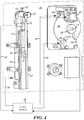
Figure 1 is a side view of a creel showing the composite material spools, dancer rolls, and interleaver rollers mounted on the outside walls of the creel, and a composite placement head mounted on the bottom of the creel. -
Figure 2 is a detail view of one of the creel walls shown inFigure 1 showing the path of composite material payout from the spools. -
Figure 3 shows the opposite side of the creel wall ofFigure 2 . -
Figure 4 is a detail view of section 4 of the tensioning mechanisms shown inFigure 3 . -
Figure 5 is a block diagram of the control system for the tensioning system. - Turning now to
Figure 1 , a creel with a head mounted thereon is generally designated by thereference numeral 10. Thecreel 11 has a generally rectangular shape and has generally rectangular side walls 12-14 (only 3 walls are shown) that provide support for a number ofspools 15 of composite material ortow 18. Acomposite placement head 16 is attached to the underside orbottom wall 17 of the creel, and a compaction roller orshoe 20 is provided at the bottom of thehead 16 to press thecomposite material 18 onto anapplication surface 22. Thecomposite placement head 16 has ahead centerline 19 which passes through the center of thecreel 11 and the compaction roller orshoe 20. Thecreel 11 may be attached to the end of apositioning mechanism 23 which maneuvers thehead 16 and thecompaction roller 20 to various positions and locations so that the composite material may be applied in a desired location and pattern on theapplication surface 22. As used herein, the term composite material is used to designate resin impregnated fiber, tow, slit tape, prepreg materials, and other similar materials, all of which are well known to those skilled in the art, and all of which terms are used interchangeably in this application. - As shown in
Figure 2 , theoutside wall 12 of thecreel 11 supports four spindles 26, each of which supports aspool 15 of composite material. Adjacent to each spindle 26 is an interleaver take-up roll 27 and a dancer roll 30. The interleaver take-up roll 27 winds up the paper separator strip from thespool 15 ofcomposite material 18 for eventual disposal. Thedancer roll 30 is mounted on a dancer roll support bracket 33 (best seen inFigure 4 ) for sliding motion on a linear slide orway 32. Eachdancer roll 30 has an axial length approximately equal to the axial length of theadjacent spool 15 ofcomposite material 18 to allow a helical unwinding of thematerial 18 from thespool 15 without side loads being created on the material by the dancer roll 30. -
Figure 2 shows the path of thecomposite material 18 from thespool 15 to the interleaver take-up roll 27, then around the interleaver take-up roll 27 to the dancer roll 30, and around the dancer roll 30 to anedge roller 35 that directs thecomposite material 18 to thehead 16. Each side of the remaining three adjacent sides of thecreel 11 may have a similar outside wall with a similar pattern of spindles 26 and dancer rolls 30, or the outside walls of thecreel 11 may have different numbers of spindles and dancer rolls, or may have a different pattern of spindles and dancer rolls depending on packaging and performance requirements. -
Figure 3 shows theback surface 36 of theoutside creel wall 12 ofFigure 2 , andFigure 4 is a detail view of the one of the tensioning mechanisms shown inFigure 3 . Theshaft 37 from each of the spindles 26 on the front of theoutside wall 12 extends through thewall 12 and has abrake rotor 38 attached to it. One or moredrag brake cylinders 42, each having a brake pad (not shown) are coupled to thewall 36 in proximity to the surface of thebrake rotor 38. If twodrag brake cylinders 42 are used, they may be coupled to thewall 36 on opposite sides of thebrake rotor 38 in a mirror image position relative to one another. Thedrag brake cylinders 42 are coupled by a dragbrake control line 45 to acontrol system 46. Thedrag brake cylinders 42 may be electrical, hydraulic or pneumatically operated. In the preferred embodiment, pneumatic brakes were used. A lockingbrake 48 having a brake mechanism that engages one or both sides of thebrake rotor 38 may be attached to thewall 36. The lockingbrake 48 may have a lockingbrake control line 49 that is coupled to thecontrol system 46. The lockingbrake 48 may be electrical, hydraulic or pneumatically operated. In the preferred embodiment, a pneumatic brake was used. Arotary encoder 50 may be attached to the end of theshaft 37 from the spindle 26, and the output signals from therotary encoder 50 may be coupled by an encoder cable 51 to thecontrol system 46. - A
dancer roll cylinder 54 may be provided for each of the dancer rolls 30 on the front of theoutside wall 12. Thedancer roll cylinder 54 may be coupled to thecontrol system 46 by a dancerroll cylinder line 56. Eachdancer roll cylinder 54 may have a cylinder rod 57 connected to apiston 58 inside of thecylinder 54. The cylinder rod 57 may be coupled to the dancerroll support bracket 33 that extends through the linear slide orway 32 on wall of the creel and may be coupled to adancer roll 30 on the front of theoutside wall 12. Each dancerroll support bracket 33 may be coupled to a connectingrod 59 that is coupled to aninput slide 61 on a linear position feedback sensor such as linear variable displacement transformer (LVDT) 62 that is mounted on thesurface 36. TheLVDT 62 may generate signals representing the movement of thedancer roll cylinder 30, and sends the signals via aLVDT cable 63 to thecontrol system 46. Thedancer roll cylinder 30 may be electrical, hydraulic or pneumatically operated. In the preferred embodiment, a pneumatic cylinder was used. -
Figure 5 is a block diagram of thecontrol system 46 for the passive tensioning system described in connection withFigures 1-4 . The composite placement system uses aCNC control 68 which determines the movement of thehead 16 relative to theapplication surface 22 and the placement of composite material on theapplication surface 22 by thehead 16. A value for the tension of the composite material may be set by an operator by means of a tension setpoint control 65 contained in theCNC control 68. The tension set point is then processed by thetension control software 67, and thetension control software 67 operates together with theCNC control 68 to meter the payout ofcomposite material 15 from thehead 16. Thetension control software 67 couples commands to an input/output device 66 such as an industrial IO system. The input/output device 66 generates a drag brake pressureanalog output signal 70 that is coupled to a drag brake electro-pneumatic regulator 72. Theregulator 72 is coupled to thedrag brake cylinders 42 which act on therotor 38 that is coupled to the spool ofmaterial 15. The rotation of the spool ofmaterial 15 is sensed by theencoder 50 which generates an encoder input 51 that is coupled to the input/output device 66. - The
input output device 66 also generates a dancer arm pressureanalog output signal 75 that is coupled to a dancer arm electro-pneumatic regulator 76 the output of which is coupled to thedancer roll cylinder 54. Changing the pressure in thedancer roll cylinder 54 changes the response characteristics of thedancer roll 30. The position of thedancer roll 30 is sensed by the linearposition feedback cylinder 62. The linearposition feedback cylinder 62 generates a signal that is coupled by theLVDT cable 63 to theoutput device 66. - In operation, the tensioner system adjusts dynamically to the specific operations that are being performed by the composite placement system. The force of the
dancer roll 30 is adjusted by the electro-pneumatic regulator 76 and thedancer roll cylinder 54 so that thedancer roll 30 acts like an adjustable spring. Thedancer roll cylinder 54 may be a double acting cylinder that may have a constant back pressure on the end carrying the cylinder rod 57 and an adjustable pressure on the end which is coupled to the dancerroll cylinder cable 56 to produce a smooth, varying, spring force movement. Other cylinder designs may be used. Increasing the pressure in thedancer roll cylinder 54 increases the force necessary to depress thedancer roll 30 from the top of its travel in the linear slide orway 32 to the bottom. The force of thedrag brakes 42 on thebrake rotor 38 and the spring force on thedancer roll 30 vary with the signal from the tension setpoint control 65 that may be set into thecontrol system 68 by the operator. The tension set point control is typically set to that the tension on the tow is less than 0,45 kg (one pound). Signals from therotary encoder 50 may be used to determine the diameter of the composite material on thespool 15, the inertia of thespool 15, the speed of rotation of thespool 15, and the acceleration of thespool 15. Using this data, the dancer roll spring force may be adjusted dynamically by thetension control software 67 based on the diameter of thespool 15, the inertia of thespool 15, and the acceleration of thespool 15. The force of thedrag brakes 42 on the spool is dynamically adjusted based on the diameter of thespool 15, the inertia of thespool 15, and the speed and acceleration of thespool 15. - The tensioner is used on a composite placement system during the time that composite material on the
spool 15 is fed out and applied to asurface 22. At the end of a laydown path, the feed ofmaterial 18 to thehead 16 may be abruptly stopped so that thematerial 18 may be cut as needed. These operations may be performed as fast as possible, resulting in high spool accelerations and decelerations. TheCNC control 68 commands when these operations are to occur. During these occurrences, the timing and amount of the force on thedrag brakes 42, and the timing and amount of force exerted by thepneumatic cylinder 54 on thedancer roll 30 may be instantaneously adjusted in real time. - In preparation for a material payout operation, the
dancer roll 30 is pushed to the top of thelinear slide 32 before the payout of composite material occurs. This allows thedancer roll 30 to have the maximum travel range as thetow 18 is fed out at high speed. When a tow feed command is sent from thecontroller 68, the dancer roll travels 30 towards bottom of thelinear slide 32 astow 18 is fed out from amaterial spool 15 in order to absorb a portion of the acceleration force on thematerial spool 15. This reduces the tension on thetow 18 during the feed operation which helps to maintain the tow set tension accuracy and the tow laydown position accuracy. The control of thedancer roll 30 by thepneumatic cylinder 54 allows the control system to optimize the motion of the dancer roll to help control the tension on thetow 18 during the various operations. Controlling thedancer roller 30 with the pneumaticdancer roll cylinder 54 allows the spring rate of thedancer roll 30 to change as needed to compensate for various dynamic events, such as a different size roll of material, or a different tension setpoint, or an extremely high acceleration or deceleration. The spring rate of thepneumatic cylinder 54 can also be varied as a function of the position of thedancer roll 30. - During a cutting operation, the supply of
tow 18 from thespool 15 needs to stop suddenly. Thedrag brakes 42 are tightened against thebrake rotor 38 to stop thespool 15 quickly to prevent the tow from unspooling. Additionally, the pressure in thedancer roll cylinder 54 is altered to cushion the stopping motion of the system. - The
creel 11 may be mounted on theend effector 23 of a composite placement machine. As theend effector 23 is maneuvered in three directions under the control of theCNC control 68, thecreel 11 is tilted. Tilting thecreel 11 repositions the gravity vector relative to thehead centerline 19, and the effective force due to the component weight of thedancer roll 30 changes and may be programmed into theCNC control 68. The pressure in thedancer roll cylinder 54 may be changed accordingly in order to compensate for the gravity vector force change seen by thedancer roll 30 due to the repositioning of thedancer roll 30 relative to gravity. - The
encoder 50 is mounted to thematerial spool shaft 37 to detect the change of angular position of thespool 15 in response to a payout command in order to compute the diameter of thespool 50 in real time. The real time diameter of thespool 50 is used to adjust the force of thedrag brakes 42 on thebrake rotor 38 and the effective spring force on thedancer roll 30 to control the tension on thetow 18 more effectively. - The locking
brake 48 is provided to lock thebrake rotor 38 and thereby thespool 15 against rotation during certain machine modes such as for head servicing, head changing, or spool changing. - The passive tensioner described above provides the following advantages:
- 1. The elimination of expensive bidirectional servoed tensioner motors controlling the tension.
- 2. The ability to operate in all orientations.
- 3. The ability to be tightly packaged on a head that includes a creel.
- 4. The ability to operate at low set point tensions of less than 0,23 kg (one half-pound).
- 5. The ability to separate the effects of spool inertial loads from changing the low tension control of the tow.
- If the spools and passive tensioner described above reside in a creel that is separate from the head, and the head moves toward and away from the creel thus generating fiber slack, a fiber festoon may be used to take up the slack. A fiber festoon will enable real time slack elimination during machine motion to compensate for the passive tensioner's inability to reverse to remove fiber slack. Although the device described uses pneumatic based force output devices, those skilled in the art will understand that electric force output devices may be used.
- Having thus described the device, various modifications and alterations will occur to those skilled in the art, which modifications and alterations are intended to be within the scope of the invention as defined by the appended claims.
Claims (18)
- A passive tensioning system for composite material (18) dispensed by a composite placement machine in which material on a spool (15) mounted on a spool shaft (37) is pulled off over a dancer roll (30) and applied to a surface (22), the passive tensioning system comprising:- the spool shaft (37);- a drag brake (42) on the spool shaft (37);- a drag brake control (72) for the drag brake (42);- the dancer roll (30) mounted on a linear slide (32) having a spring force;
characterized by- a control (76) for varying the force for the linear slide (32);- a pneumatic cylinder (54) coupled to the linear slide (32)for adjusting the dancer roll spring force by varying a pressure in the pneumatic cylinder (54) such that the dancer roll (30) acts like an adjustable spring; and,- a control system (46) for continually varying the drag brake control (72) and the slide control (76) to control the tension of the composite material (18) based on the instantaneous operating characteristics of the composite placement machine;wherein the dancer roll (30) is capable of being pushed to the top of the linear slide (32) before dispensing of composite material (18) occurs, whereby the dancer roll (30) has a maximum range of travel on the linear slide (32) as composite material (18) is paid out; and,wherein the pressure in the pneumatic cylinder (54) is capable of being changed in order to compensate for a gravity vector force change seen by the dancer roll (30) due to repositioning the dancer roll (30) relative to gravity, whereby the passive tensioning system is able to operate in all orientations. - The passive tensioning system of claim 1 further comprising a linear position feedback device (62) for the linear slide adapted to vary the slide force for the linear slide (32) according to a position of the linear slide (32).
- The passive tensioning system of claim 1 further comprising an encoder (50) mounted on the spool shaft (37) adapted to provide angular position feedback for the spool (15) and to vary the drag brake control (72) according to the change in angular position of the spool (15).
- The passive tensioning system of claim 1 further comprising a double acting cylinder comprising the pneumatic cylinder (54).
- The passive tensioning system of claim 1 further comprising a linear position feedback device (62) for the dancer roll (30) adapted to vary the dancer roll spring force according to the linear position of the dancer roll (30).
- The passive tensioning system of claim 1 further comprising a tension set point control (65) for the control system (46) adapted to set the tension on the composite material (18) to a specific value, and to apply a braking force by the drag brake (42) and to vary the spring force on the dancer roll (30) according to the tension set point control (65).
- The passive tensioning system of claim 1 further comprising a spool diameter measuring system (50) adapted to measure the diameter of the spool (15) as composite material (18) is fed out from the spool (15) and to dynamically adjust the drag brake force based on the diameter of the spool (15).
- The passive tensioning system of claim 1 further comprising a rotary encoder (50) coupled to the spool shaft (37) and having an encoder output signal, the encoder output signal coupled to the control system (46) adapted to measure the acceleration of the spool (15) and the inertia of the spool (15), and to dynamically adjust the drag brake force based on the acceleration of the spool (15) and the inertia of the spool (15).
- The passive tensioning system of claim 8 wherein the control system (46) is capable of measuring the speed of rotation of the spool (15), whereby braking force applied by the drag brake (42) on the spool shaft (37) is adjustable based on the speed of rotation of the spool (15).
- The passive tensioning system of claim 1 wherein the dancer roll spring force is dynamically adjustable based on the position of the dancer roll linear slide (32).
- The passive tensioning system of claim 1 wherein the dancer roll spring force is dynamically adjustable based on the inertia of the spool (15).
- The passive tensioning system of claim 1 wherein the dancer roll spring force is dynamically adjustable based on the acceleration of the spool (15).
- The passive tensioning system of claim 1 wherein the spool (15) has a diameter and the drag brake (42) on the spool (15) is dynamically adjustable based on the diameter of the spool (15).
- The passive tensioning system of claim 1 wherein the spool (15) has an inertia and the drag brake (42) on the spool (15) is dynamically adjustable based on the inertia of the spool (15).
- The passive tensioning system of claim 1 wherein the spool (15) has a speed of rotation and the drag brake (42) on the spool (15) is dynamically adjustable based on the speed of the spool (15).
- The passive tensioning system of claim 1 wherein the spool (15) has an acceleration and the drag brake (42) on the spool (15) is dynamically adjustable based on the acceleration of the spool (15).
- The passive tensioning system of claim 6 wherein the tension set point control (65) is capable of being set to less than 0,45 kg (one pound).
- The passive tensioning system of claim 6 wherein the tension set point control (65) is capable of being set to less than 0,23 kg (one half pound).
Applications Claiming Priority (2)
| Application Number | Priority Date | Filing Date | Title |
|---|---|---|---|
| US14/881,480 US10000357B2 (en) | 2015-10-13 | 2015-10-13 | Passive tensioning system for composite material payout control |
| PCT/US2016/056408 WO2017066178A1 (en) | 2015-10-13 | 2016-10-11 | Passive tensioning system for composite material payout control |
Publications (3)
| Publication Number | Publication Date |
|---|---|
| EP3362391A1 EP3362391A1 (en) | 2018-08-22 |
| EP3362391A4 EP3362391A4 (en) | 2018-12-26 |
| EP3362391B1 true EP3362391B1 (en) | 2019-12-04 |
Family
ID=58499577
Family Applications (1)
| Application Number | Title | Priority Date | Filing Date |
|---|---|---|---|
| EP16856030.8A Active EP3362391B1 (en) | 2015-10-13 | 2016-10-11 | Passive tensioning system for composite material payout control |
Country Status (8)
| Country | Link |
|---|---|
| US (1) | US10000357B2 (en) |
| EP (1) | EP3362391B1 (en) |
| JP (1) | JP6841822B2 (en) |
| CN (1) | CN108473268B (en) |
| CA (1) | CA3001911C (en) |
| ES (1) | ES2773153T3 (en) |
| RU (1) | RU2719038C2 (en) |
| WO (1) | WO2017066178A1 (en) |
Families Citing this family (17)
| Publication number | Priority date | Publication date | Assignee | Title |
|---|---|---|---|---|
| US9511543B2 (en) | 2012-08-29 | 2016-12-06 | Cc3D Llc | Method and apparatus for continuous composite three-dimensional printing |
| US20210094230A9 (en) * | 2016-11-04 | 2021-04-01 | Continuous Composites Inc. | System for additive manufacturing |
| GB2561914B (en) * | 2017-04-28 | 2022-04-27 | Hexcel Reinforcements Uk Ltd | Apparatus for and method of fibre placement for the formation of fibre preforms |
| JP6928998B2 (en) * | 2017-05-31 | 2021-09-01 | Nittoku株式会社 | Tension device |
| DE202017106345U1 (en) * | 2017-10-19 | 2019-01-25 | Broetje-Automation Gmbh | end effector |
| CN108582814B (en) * | 2018-05-25 | 2023-11-03 | 中国科学院自动化研究所 | Single-drive composite material wire laying head integrated device and heavy-duty wheel shaft system thereof |
| CN108749034A (en) * | 2018-06-11 | 2018-11-06 | 浙江大学 | A kind of piddler head being integrated with tow convergence |
| FR3085880B1 (en) * | 2018-09-18 | 2022-04-15 | Energiestro | PROCESS FOR SHRINKING A CYLINDRICAL PART BY WINDING FIBERS UNDER TENSION |
| CN109205392A (en) * | 2018-09-28 | 2019-01-15 | 安溪达亚齐机械设计有限公司 | Pierce riveting up- coiler |
| US10981342B2 (en) * | 2018-11-13 | 2021-04-20 | Electroimpact, Inc. | Servo motor tension control for modular AFP head assembly |
| JP7261398B2 (en) | 2018-12-24 | 2023-04-20 | 河政工業株式会社 | Optical fiber winding mechanism and optical path manufacturing method for optical fiber gyro |
| US20220176652A1 (en) * | 2019-03-29 | 2022-06-09 | Toray Industries, Inc. | Fiber placement device |
| US11312083B2 (en) | 2019-05-28 | 2022-04-26 | Continuous Composites Inc. | System for additively manufacturing composite structure |
| US20240125014A1 (en) * | 2019-10-17 | 2024-04-18 | Rjs Corporation | Digital creel system |
| CN116034013A (en) * | 2020-09-04 | 2023-04-28 | 法孚机械加工系统股份有限公司 | Fiber placement machine for removing composite belt film |
| US11813793B2 (en) * | 2020-09-11 | 2023-11-14 | Continuous Composites Inc. | Print head for additive manufacturing system |
| CN114488814B (en) * | 2022-01-26 | 2023-05-30 | 中国航空制造技术研究院 | High-precision laying tension control method for eliminating gravity disturbance |
Family Cites Families (13)
| Publication number | Priority date | Publication date | Assignee | Title |
|---|---|---|---|---|
| SU608736A1 (en) * | 1976-10-08 | 1978-05-30 | Предприятие П/Я В-8406 | Web-unwinding apparatus |
| JPH06611B2 (en) | 1986-10-04 | 1994-01-05 | 株式会社ニレコ | Control method in dancer roll type tension control device |
| SU1406260A1 (en) * | 1986-11-28 | 1988-06-30 | Научно-Производственное Объединение По Оборудованию Для Химических Волокон "Химтекстильмаш" | Arrangement for conveying continuous fibrous material |
| SU1646974A1 (en) * | 1988-12-19 | 1991-05-07 | Гомельский политехнический институт | Device for controlling tension of continuous material |
| JP3943235B2 (en) * | 1998-04-14 | 2007-07-11 | 株式会社ブリヂストン | Constant tension wire unwinding device |
| EP1299301B1 (en) * | 2000-07-11 | 2004-11-03 | Corning Incorporated | Variable tension fiber winding |
| CN100451203C (en) | 2004-05-09 | 2009-01-14 | 上海哈依投资咨询有限公司 | Wire material supplying mechanism of tubular braided fabric braiding machine |
| JP2007069940A (en) | 2005-09-06 | 2007-03-22 | Ishida Co Ltd | Feeding apparatus, vertical type bag manufacturing and packaging machine, and metering and packaging system |
| JP2007268631A (en) * | 2006-03-30 | 2007-10-18 | Fanuc Ltd | Wire electrode supply device of wire cut electric discharge machine |
| CN101918628B (en) | 2008-01-23 | 2012-03-21 | 大建工业株式会社 | Cylindrical twisted-yarn manufacturing apparatus |
| ES2372843B1 (en) * | 2010-07-14 | 2012-09-17 | Manuel Torres Martínez | APPLICATOR HEAD OF FIBER STRIPS. |
| US8997818B2 (en) | 2013-02-27 | 2015-04-07 | Fives Machining Systems, Inc. | Device for fabricating a composite structure |
| RU2615478C1 (en) * | 2015-11-25 | 2017-04-04 | Федеральное Государственное Унитарное Предприятие "Научно-Производственное Объединение "Техномаш" | Winding machine |
-
2015
- 2015-10-13 US US14/881,480 patent/US10000357B2/en active Active
-
2016
- 2016-10-11 CA CA3001911A patent/CA3001911C/en active Active
- 2016-10-11 WO PCT/US2016/056408 patent/WO2017066178A1/en active Application Filing
- 2016-10-11 RU RU2018117382A patent/RU2719038C2/en active
- 2016-10-11 EP EP16856030.8A patent/EP3362391B1/en active Active
- 2016-10-11 ES ES16856030T patent/ES2773153T3/en active Active
- 2016-10-11 CN CN201680060243.1A patent/CN108473268B/en active Active
- 2016-10-11 JP JP2018519817A patent/JP6841822B2/en active Active
Non-Patent Citations (1)
| Title |
|---|
| None * |
Also Published As
| Publication number | Publication date |
|---|---|
| JP6841822B2 (en) | 2021-03-10 |
| CA3001911C (en) | 2022-01-25 |
| JP2018530489A (en) | 2018-10-18 |
| CA3001911A1 (en) | 2017-04-20 |
| CN108473268A (en) | 2018-08-31 |
| RU2719038C2 (en) | 2020-04-16 |
| EP3362391A4 (en) | 2018-12-26 |
| RU2018117382A3 (en) | 2020-01-17 |
| CN108473268B (en) | 2020-08-04 |
| US10000357B2 (en) | 2018-06-19 |
| EP3362391A1 (en) | 2018-08-22 |
| ES2773153T3 (en) | 2020-07-09 |
| RU2018117382A (en) | 2019-11-14 |
| WO2017066178A9 (en) | 2018-05-03 |
| WO2017066178A1 (en) | 2017-04-20 |
| US20170101286A1 (en) | 2017-04-13 |
Similar Documents
| Publication | Publication Date | Title |
|---|---|---|
| EP3362391B1 (en) | Passive tensioning system for composite material payout control | |
| KR20200125284A (en) | Fiber tension control device and tension control method using the same | |
| KR102407024B1 (en) | Tension Control Direct Driven Roller Festoon | |
| KR20150024266A (en) | Tension providing apparatus of elongated object and tension providing method thereof | |
| US4565334A (en) | Electrohydraulic drive for process line winders, unwinders and other equipment | |
| US4838498A (en) | Web tensioning system | |
| WO1995018762A1 (en) | Web reel brake control system | |
| US5035372A (en) | Winding device for a yarn, in particular for a yarn with approximately zero elongation | |
| EP1129971B1 (en) | Paper roll braking device | |
| CN214455528U (en) | Tension adjusting device | |
| DE19512963A1 (en) | Tape dispenser for long roll of material e.g. wire foil, light waveguide, thread or filament | |
| EP1507726B1 (en) | Device and method for controlling the tension of a weblike material | |
| US6457667B1 (en) | Method and apparatus for controlling the tension of wire being pulled from a wire spool on a bead wire letoff stand | |
| JP3533165B2 (en) | Yarn sheet winder | |
| JPH02242942A (en) | Apparatus for controlling tension of running yarn | |
| JP7148621B2 (en) | Device for cutting material webs into individual sheets in web storage | |
| KR20180089948A (en) | Parallel Winding Device and Method | |
| JP2816255B2 (en) | Tension control device | |
| JP7357428B2 (en) | Winding device and winding method | |
| CA2627707C (en) | Method of winding web reel and web winding apparatus | |
| CN213679210U (en) | Wire arranging device for winding and unwinding mooring cable of unmanned aerial vehicle | |
| JPH03199445A (en) | Device for controlling tension of travelling yarn | |
| JPH0510172B2 (en) | ||
| WO1999040011A1 (en) | Method and apparatus for controlling the tension of bead wire being pulled from a wire spool | |
| CS257423B1 (en) | Device for yarn winding on cones on textile machines |
Legal Events
| Date | Code | Title | Description |
|---|---|---|---|
| STAA | Information on the status of an ep patent application or granted ep patent |
Free format text: STATUS: THE INTERNATIONAL PUBLICATION HAS BEEN MADE |
|
| PUAI | Public reference made under article 153(3) epc to a published international application that has entered the european phase |
Free format text: ORIGINAL CODE: 0009012 |
|
| STAA | Information on the status of an ep patent application or granted ep patent |
Free format text: STATUS: REQUEST FOR EXAMINATION WAS MADE |
|
| 17P | Request for examination filed |
Effective date: 20180502 |
|
| AK | Designated contracting states |
Kind code of ref document: A1 Designated state(s): AL AT BE BG CH CY CZ DE DK EE ES FI FR GB GR HR HU IE IS IT LI LT LU LV MC MK MT NL NO PL PT RO RS SE SI SK SM TR |
|
| AX | Request for extension of the european patent |
Extension state: BA ME |
|
| A4 | Supplementary search report drawn up and despatched |
Effective date: 20181123 |
|
| RIC1 | Information provided on ipc code assigned before grant |
Ipc: B65H 59/36 20060101ALI20181119BHEP Ipc: B65H 59/04 20060101AFI20181119BHEP Ipc: B29C 70/30 20060101ALI20181119BHEP |
|
| DAV | Request for validation of the european patent (deleted) | ||
| DAX | Request for extension of the european patent (deleted) | ||
| REG | Reference to a national code |
Ref country code: DE Ref legal event code: R079 Ref document number: 602016025815 Country of ref document: DE Free format text: PREVIOUS MAIN CLASS: B65H0059000000 Ipc: B65H0059040000 |
|
| GRAP | Despatch of communication of intention to grant a patent |
Free format text: ORIGINAL CODE: EPIDOSNIGR1 |
|
| STAA | Information on the status of an ep patent application or granted ep patent |
Free format text: STATUS: GRANT OF PATENT IS INTENDED |
|
| RIC1 | Information provided on ipc code assigned before grant |
Ipc: B29C 70/38 20060101ALI20190702BHEP Ipc: B29C 70/56 20060101ALI20190702BHEP Ipc: B65H 59/36 20060101ALI20190702BHEP Ipc: B65H 59/04 20060101AFI20190702BHEP |
|
| INTG | Intention to grant announced |
Effective date: 20190717 |
|
| GRAS | Grant fee paid |
Free format text: ORIGINAL CODE: EPIDOSNIGR3 |
|
| GRAA | (expected) grant |
Free format text: ORIGINAL CODE: 0009210 |
|
| STAA | Information on the status of an ep patent application or granted ep patent |
Free format text: STATUS: THE PATENT HAS BEEN GRANTED |
|
| AK | Designated contracting states |
Kind code of ref document: B1 Designated state(s): AL AT BE BG CH CY CZ DE DK EE ES FI FR GB GR HR HU IE IS IT LI LT LU LV MC MK MT NL NO PL PT RO RS SE SI SK SM TR |
|
| REG | Reference to a national code |
Ref country code: GB Ref legal event code: FG4D |
|
| REG | Reference to a national code |
Ref country code: CH Ref legal event code: EP |
|
| REG | Reference to a national code |
Ref country code: AT Ref legal event code: REF Ref document number: 1209148 Country of ref document: AT Kind code of ref document: T Effective date: 20191215 |
|
| REG | Reference to a national code |
Ref country code: DE Ref legal event code: R096 Ref document number: 602016025815 Country of ref document: DE |
|
| REG | Reference to a national code |
Ref country code: IE Ref legal event code: FG4D |
|
| REG | Reference to a national code |
Ref country code: NL Ref legal event code: MP Effective date: 20191204 |
|
| REG | Reference to a national code |
Ref country code: LT Ref legal event code: MG4D |
|
| PG25 | Lapsed in a contracting state [announced via postgrant information from national office to epo] |
Ref country code: SE Free format text: LAPSE BECAUSE OF FAILURE TO SUBMIT A TRANSLATION OF THE DESCRIPTION OR TO PAY THE FEE WITHIN THE PRESCRIBED TIME-LIMIT Effective date: 20191204 Ref country code: LV Free format text: LAPSE BECAUSE OF FAILURE TO SUBMIT A TRANSLATION OF THE DESCRIPTION OR TO PAY THE FEE WITHIN THE PRESCRIBED TIME-LIMIT Effective date: 20191204 Ref country code: NO Free format text: LAPSE BECAUSE OF FAILURE TO SUBMIT A TRANSLATION OF THE DESCRIPTION OR TO PAY THE FEE WITHIN THE PRESCRIBED TIME-LIMIT Effective date: 20200304 Ref country code: GR Free format text: LAPSE BECAUSE OF FAILURE TO SUBMIT A TRANSLATION OF THE DESCRIPTION OR TO PAY THE FEE WITHIN THE PRESCRIBED TIME-LIMIT Effective date: 20200305 Ref country code: LT Free format text: LAPSE BECAUSE OF FAILURE TO SUBMIT A TRANSLATION OF THE DESCRIPTION OR TO PAY THE FEE WITHIN THE PRESCRIBED TIME-LIMIT Effective date: 20191204 Ref country code: BG Free format text: LAPSE BECAUSE OF FAILURE TO SUBMIT A TRANSLATION OF THE DESCRIPTION OR TO PAY THE FEE WITHIN THE PRESCRIBED TIME-LIMIT Effective date: 20200304 Ref country code: FI Free format text: LAPSE BECAUSE OF FAILURE TO SUBMIT A TRANSLATION OF THE DESCRIPTION OR TO PAY THE FEE WITHIN THE PRESCRIBED TIME-LIMIT Effective date: 20191204 |
|
| PG25 | Lapsed in a contracting state [announced via postgrant information from national office to epo] |
Ref country code: RS Free format text: LAPSE BECAUSE OF FAILURE TO SUBMIT A TRANSLATION OF THE DESCRIPTION OR TO PAY THE FEE WITHIN THE PRESCRIBED TIME-LIMIT Effective date: 20191204 Ref country code: HR Free format text: LAPSE BECAUSE OF FAILURE TO SUBMIT A TRANSLATION OF THE DESCRIPTION OR TO PAY THE FEE WITHIN THE PRESCRIBED TIME-LIMIT Effective date: 20191204 |
|
| PG25 | Lapsed in a contracting state [announced via postgrant information from national office to epo] |
Ref country code: AL Free format text: LAPSE BECAUSE OF FAILURE TO SUBMIT A TRANSLATION OF THE DESCRIPTION OR TO PAY THE FEE WITHIN THE PRESCRIBED TIME-LIMIT Effective date: 20191204 |
|
| REG | Reference to a national code |
Ref country code: ES Ref legal event code: FG2A Ref document number: 2773153 Country of ref document: ES Kind code of ref document: T3 Effective date: 20200709 |
|
| PG25 | Lapsed in a contracting state [announced via postgrant information from national office to epo] |
Ref country code: PT Free format text: LAPSE BECAUSE OF FAILURE TO SUBMIT A TRANSLATION OF THE DESCRIPTION OR TO PAY THE FEE WITHIN THE PRESCRIBED TIME-LIMIT Effective date: 20200429 Ref country code: EE Free format text: LAPSE BECAUSE OF FAILURE TO SUBMIT A TRANSLATION OF THE DESCRIPTION OR TO PAY THE FEE WITHIN THE PRESCRIBED TIME-LIMIT Effective date: 20191204 Ref country code: NL Free format text: LAPSE BECAUSE OF FAILURE TO SUBMIT A TRANSLATION OF THE DESCRIPTION OR TO PAY THE FEE WITHIN THE PRESCRIBED TIME-LIMIT Effective date: 20191204 Ref country code: RO Free format text: LAPSE BECAUSE OF FAILURE TO SUBMIT A TRANSLATION OF THE DESCRIPTION OR TO PAY THE FEE WITHIN THE PRESCRIBED TIME-LIMIT Effective date: 20191204 Ref country code: CZ Free format text: LAPSE BECAUSE OF FAILURE TO SUBMIT A TRANSLATION OF THE DESCRIPTION OR TO PAY THE FEE WITHIN THE PRESCRIBED TIME-LIMIT Effective date: 20191204 |
|
| PG25 | Lapsed in a contracting state [announced via postgrant information from national office to epo] |
Ref country code: IS Free format text: LAPSE BECAUSE OF FAILURE TO SUBMIT A TRANSLATION OF THE DESCRIPTION OR TO PAY THE FEE WITHIN THE PRESCRIBED TIME-LIMIT Effective date: 20200404 Ref country code: SK Free format text: LAPSE BECAUSE OF FAILURE TO SUBMIT A TRANSLATION OF THE DESCRIPTION OR TO PAY THE FEE WITHIN THE PRESCRIBED TIME-LIMIT Effective date: 20191204 Ref country code: SM Free format text: LAPSE BECAUSE OF FAILURE TO SUBMIT A TRANSLATION OF THE DESCRIPTION OR TO PAY THE FEE WITHIN THE PRESCRIBED TIME-LIMIT Effective date: 20191204 |
|
| REG | Reference to a national code |
Ref country code: DE Ref legal event code: R097 Ref document number: 602016025815 Country of ref document: DE |
|
| REG | Reference to a national code |
Ref country code: AT Ref legal event code: MK05 Ref document number: 1209148 Country of ref document: AT Kind code of ref document: T Effective date: 20191204 |
|
| PLBE | No opposition filed within time limit |
Free format text: ORIGINAL CODE: 0009261 |
|
| STAA | Information on the status of an ep patent application or granted ep patent |
Free format text: STATUS: NO OPPOSITION FILED WITHIN TIME LIMIT |
|
| PG25 | Lapsed in a contracting state [announced via postgrant information from national office to epo] |
Ref country code: DK Free format text: LAPSE BECAUSE OF FAILURE TO SUBMIT A TRANSLATION OF THE DESCRIPTION OR TO PAY THE FEE WITHIN THE PRESCRIBED TIME-LIMIT Effective date: 20191204 |
|
| 26N | No opposition filed |
Effective date: 20200907 |
|
| PG25 | Lapsed in a contracting state [announced via postgrant information from national office to epo] |
Ref country code: PL Free format text: LAPSE BECAUSE OF FAILURE TO SUBMIT A TRANSLATION OF THE DESCRIPTION OR TO PAY THE FEE WITHIN THE PRESCRIBED TIME-LIMIT Effective date: 20191204 Ref country code: SI Free format text: LAPSE BECAUSE OF FAILURE TO SUBMIT A TRANSLATION OF THE DESCRIPTION OR TO PAY THE FEE WITHIN THE PRESCRIBED TIME-LIMIT Effective date: 20191204 Ref country code: AT Free format text: LAPSE BECAUSE OF FAILURE TO SUBMIT A TRANSLATION OF THE DESCRIPTION OR TO PAY THE FEE WITHIN THE PRESCRIBED TIME-LIMIT Effective date: 20191204 |
|
| GBPC | Gb: european patent ceased through non-payment of renewal fee |
Effective date: 20201011 |
|
| PG25 | Lapsed in a contracting state [announced via postgrant information from national office to epo] |
Ref country code: LU Free format text: LAPSE BECAUSE OF NON-PAYMENT OF DUE FEES Effective date: 20201011 Ref country code: MC Free format text: LAPSE BECAUSE OF FAILURE TO SUBMIT A TRANSLATION OF THE DESCRIPTION OR TO PAY THE FEE WITHIN THE PRESCRIBED TIME-LIMIT Effective date: 20191204 |
|
| REG | Reference to a national code |
Ref country code: BE Ref legal event code: MM Effective date: 20201031 |
|
| PG25 | Lapsed in a contracting state [announced via postgrant information from national office to epo] |
Ref country code: BE Free format text: LAPSE BECAUSE OF NON-PAYMENT OF DUE FEES Effective date: 20201031 Ref country code: GB Free format text: LAPSE BECAUSE OF NON-PAYMENT OF DUE FEES Effective date: 20201011 |
|
| PG25 | Lapsed in a contracting state [announced via postgrant information from national office to epo] |
Ref country code: IE Free format text: LAPSE BECAUSE OF NON-PAYMENT OF DUE FEES Effective date: 20201011 |
|
| PG25 | Lapsed in a contracting state [announced via postgrant information from national office to epo] |
Ref country code: TR Free format text: LAPSE BECAUSE OF FAILURE TO SUBMIT A TRANSLATION OF THE DESCRIPTION OR TO PAY THE FEE WITHIN THE PRESCRIBED TIME-LIMIT Effective date: 20191204 Ref country code: MT Free format text: LAPSE BECAUSE OF FAILURE TO SUBMIT A TRANSLATION OF THE DESCRIPTION OR TO PAY THE FEE WITHIN THE PRESCRIBED TIME-LIMIT Effective date: 20191204 Ref country code: CY Free format text: LAPSE BECAUSE OF FAILURE TO SUBMIT A TRANSLATION OF THE DESCRIPTION OR TO PAY THE FEE WITHIN THE PRESCRIBED TIME-LIMIT Effective date: 20191204 |
|
| PG25 | Lapsed in a contracting state [announced via postgrant information from national office to epo] |
Ref country code: MK Free format text: LAPSE BECAUSE OF FAILURE TO SUBMIT A TRANSLATION OF THE DESCRIPTION OR TO PAY THE FEE WITHIN THE PRESCRIBED TIME-LIMIT Effective date: 20191204 |
|
| PGFP | Annual fee paid to national office [announced via postgrant information from national office to epo] |
Ref country code: IT Payment date: 20230920 Year of fee payment: 8 |
|
| PGFP | Annual fee paid to national office [announced via postgrant information from national office to epo] |
Ref country code: FR Payment date: 20230920 Year of fee payment: 8 |
|
| PGFP | Annual fee paid to national office [announced via postgrant information from national office to epo] |
Ref country code: ES Payment date: 20231102 Year of fee payment: 8 |
|
| PGFP | Annual fee paid to national office [announced via postgrant information from national office to epo] |
Ref country code: DE Payment date: 20230920 Year of fee payment: 8 Ref country code: CH Payment date: 20231102 Year of fee payment: 8 |