EP0950629A2 - Apparatus for unwinding wire material under constant tension - Google Patents
Apparatus for unwinding wire material under constant tension Download PDFInfo
- Publication number
- EP0950629A2 EP0950629A2 EP99302795A EP99302795A EP0950629A2 EP 0950629 A2 EP0950629 A2 EP 0950629A2 EP 99302795 A EP99302795 A EP 99302795A EP 99302795 A EP99302795 A EP 99302795A EP 0950629 A2 EP0950629 A2 EP 0950629A2
- Authority
- EP
- European Patent Office
- Prior art keywords
- brake band
- brake
- control means
- tension
- wire material
- Prior art date
- Legal status (The legal status is an assumption and is not a legal conclusion. Google has not performed a legal analysis and makes no representation as to the accuracy of the status listed.)
- Granted
Links
Images



Classifications
-
- B—PERFORMING OPERATIONS; TRANSPORTING
- B65—CONVEYING; PACKING; STORING; HANDLING THIN OR FILAMENTARY MATERIAL
- B65H—HANDLING THIN OR FILAMENTARY MATERIAL, e.g. SHEETS, WEBS, CABLES
- B65H59/00—Adjusting or controlling tension in filamentary material, e.g. for preventing snarling; Applications of tension indicators
- B65H59/02—Adjusting or controlling tension in filamentary material, e.g. for preventing snarling; Applications of tension indicators by regulating delivery of material from supply package
- B65H59/04—Adjusting or controlling tension in filamentary material, e.g. for preventing snarling; Applications of tension indicators by regulating delivery of material from supply package by devices acting on package or support
-
- B—PERFORMING OPERATIONS; TRANSPORTING
- B65—CONVEYING; PACKING; STORING; HANDLING THIN OR FILAMENTARY MATERIAL
- B65H—HANDLING THIN OR FILAMENTARY MATERIAL, e.g. SHEETS, WEBS, CABLES
- B65H2801/00—Application field
- B65H2801/93—Tyres
Definitions
- This invention relates to an apparatus for unwinding a wire material from a reel, spool or the like under constant tension.
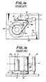
- Fig. 1 is shown an embodiment of the conventional apparatus for unwinding a wire material under constant tension, in which a reel 20 winding a wire material 22 is placed on a spindle shaft 1 by inserting a support portion 2 of the shaft 1 into a hole 21 of the reel 20.
- the wire material 22 is unwound from the reel 20 through fixed rolls 10, 11 and a dancer roll 6 as shown by a phantom line.
- the dancer roll 6 is placed on an end of a rotatably arranged dancer arm 7.
- a cylindrical portion 13 is coaxially arranged on the dancer arm 7 with respect to the rotating axis thereof.
- a brake band 4 is connected at its one end to the dancer arm 7 and fixed at the other end to a fixed portion 12 through contacting with the cylindrical portion 13 and a braking face 3.
- the dancer arm 7 is energized by a spring 8 fixed at its one end to a spring fixed portion 14 in a direction shown by an arrow X or in a direction of increasing a tension of the brake band 4 to increase a contact pressure to the braking face 3.
- the dancer arm 7 is subjected to a rotating force by the tension of the wire material 22 through the dancer roll 6 in a direction shown by an arrow Y or in a direction of decreasing the tension of the brake band 4 to decrease the contact pressure to the braking face 3.
- a braking force to the rotation of the spindle shaft 1 is controlled by a balance between the rotating force and the energizing force through the spring 8.
- the dancer arm 7 rotates in the direction of arrow X and hence the tension of the bake band 4 and the contact pressure to the braking face 3 are increased to increase the tension of the wire material 22.
- the dancer arm 7 rotates in the direction of arrow Y and hence the tension of the bake band 4 and the contact pressure to the braking face 3 are decreased to decrease the tension of the wire material 22.
- a phantom line W1 shows a state of loosing the brake band 4 to form a curved deformation in the vicinity of the contact portion with the braking face 3.
- the contact area to the braking face 3 decreases to excessively decrease the braking force and hence there is caused a problem that the tension change of the wire material 22 becomes large.
- the tension of the brake band 4 rapidly increases to increase the tension of the wire material 22 and hence there is caused a problem that breakage or hunting phenomenon of the wire material occurs.
- an object of the invention to solve the aforementioned problems in the conventional unwinding apparatus and to provide an apparatus for unwinding a wire material capable of smoothly controlling the unwinding tension of the wire material even if the tension of the brake band decreases and always unwinding the wire material under a stable tension.
- an apparatus for unwinding a wire material under constant tension which comprises a braking face rotating together with a reel wound with a wire material, a brake band contacting with the braking face and a brake control means connected to an end of the brake band for controlling a tension of the brake band to control a braking force, characterized by providing a deformation control means for restricting deformation in at least a part of the brake band.
- the deformation control means is arranged at a position near to a contact starting point of the brake band to the braking face or a position near to a connected portion of the brake band to the brake control means or at both positions in a region ranging from the brake control means to the braking face.
- the brake control means comprises a dancer arm and a brake energizing means for energizing the dancer arm in a direction of raising a contact pressure between the braking face and the brake band and the dancer arm is provided with a dancer roll and a cylindrical portion coaxially arranged with respect to a rotating axis of the roll.
- the brake band is connected at its one end to the dancer arm and arrived to the braking face through the cylindrical portion and the deformation control means is arranged so as to restrict deformation of a portion of the brake band contacting with the cylindrical portion.
- the change of the unwinding tension can be controlled even if the tension of the brake band is set to a relatively low value for unwinding the wire material under a low tension, so that a brake adjusting means for adjusting a contact pressure between the brake band and the braking face can be arranged to provide an apparatus having a high general-purpose condition.
- the deformation control means solves problems accompanied with the curved deformation of the brake band.
- a plate-shaped guide, a rod-shaped guide or the like may be arranged at one-side or both sides of the brake band and adjacent thereto.
- means for raising a rigidity of the brake band itself may be applied as the deformation control means.
- a rigid member such as a metal plate, a plastic plate or the like may be adhered to a side surface of the brake band, or a part of the brake band may be replaced with a rigid member such as a metal plate, a plastic plate or the like.
- the deformation control means When the deformation control means is arranged in the vicinity of a contact starting point of the brake band to the braking face in a region ranging from the braking face to the brake control means, there can be prevented the curved deformation of the brake band in the vicinity of the contact starting point to the braking face as shown in Fig. 1.
- the contact area between the brake band and the braking face is maintained at a constant value and the rapid change or hunting phenomenon in the tension of the wire material is prevented.
- the deformation control means in the vicinity of the contact starting point to the braking face and the deformation control means in the vicinity of the connected portion to the brake control means can be used alone, respectively, the better result is obtained by using both the deformation control means together. And also, it is effective to arrange the deformation control means over a full region ranging from the brake control means to the braking face.
- the brake control means there can be applied a complicated means wherein the unwinding tension of the wire material is electrically detected and the tension of the brake band is controlled based on the detected signal.
- the sufficient effect can be obtained even in a simple means of dancer roll system as shown in Fig. 1.
- the cylindrical portion is coaxially arranged with respect to the rotating axis of the dancer arm and the brake band is connected at its one end to the dancer arm and arrives at the braking face through the contacting with the cylindrical portion because a track of a straight line connecting the contact ending point to the cylindrical portion to the contact starting point to the braking face is unchangeable even in the rotation of the dancer arm, so that even when the plate-shaped guide, rod-shaped guide or the like as the deformation control means is arranged adjacent to the brake band, it hardly interferes the brake band.
- the deformation control means is arranged so as to restrict the deformation in a portion of the brake band contacting with the cylindrical portion while adopting the above brake control means, the control of braking force through the dancer arm is smoothly conducted and also the stability to disturbance is improved.
- a first embodiment of the unwinding apparatus for the wire material under constant tension according to the invention is described with reference to Fig. 2.
- a reel 20 wound with a wire material 22 is placed on a spindle shaft 1 by inserting a support portion of the shaft into a hole 21 of the reel, while the wire material 22 is unwound from the reel 20 through fixed rolls 10, 11 and a dancer roll 6 as shown by a phantom line.
- the spindle shaft 1 is provided with a cylindrical braking face 3 coaxially arranged with respect to a rotating axis of the shaft, so that a braking force is applied to the rotation of the spindle shaft 1 by a contact pressure to a brake band 4.
- a brake control means is constituted with the dancer arm 7 and a brake energizing means 9 for energizing the dancer arm 7 in a direction of raising the contact pressure between the braking face 3 and the brake band 4 (or in a direction shown by an arrow X).
- the brake energizing means 9 comprises a a spring 8 and a spring fixing portion 14, wherein an end of the spring 8 is fixed to the spring fixing portion 14 and the other end thereof is connected to the dancer arm 7.
- a plurality of rod-shaped guides 24 are arranged at one side of the brake band 4 and adjacent thereto in the vicinity of a contact starting point to the braking face 3 as a deformation control means 5, whereby the curved rising of the brake band 4 from the braking face 3 is prevented.
- FIG. 3 A second embodiment of the unwinding apparatus for the wire material under constant tension according to the invention is shown in Fig. 3.
- the dancer arm 7 is provided with a cylindrical portion 13 coaxially arranged with respect to the rotating axis of the arm, and the brake band 4 is fixed at its one end to the cylindrical portion 13 and arrives at the braking face 3 through contacting with the cylindrical portion 13.
- a pair of plate-shaped guides 25 are arranged on both sides of the brake band 4 and adjacent thereto in the vicinity of the connected portion to the brake control means as a deformation control means 5, whereby the curved deformation of the brake band 4 is prevented and the control of braking force through the dancer arm is smoothened.
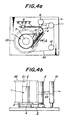
- FIG. 4 A third embodiment of the unwinding apparatus for the wire material under constant tension according to the invention is shown in Fig. 4.
- This apparatus has the same brake control means as in the second embodiment and is further provided with a brake adjusting means for adjusting the contact pressure between the brake band 4 and the braking face 3.
- the brake adjusting means is constructed by inserting a threaded end portion of the spring 8 into a through-hole of the spring fixing portion 14 and fixing the end portion through nuts 15 and 16 engaging therewith. In this case, the length of the spring 8 is adjusted by the rotation of the nuts 15, 16 to adjust an energizing force of the spring 8, whereby an unwinding tension of the wire material is set to a desired value.
- a pair of plate-shaped guides 26 are arranged on both sides of the brake band 4 and adjacent thereto over substantially a full region ranging from the brake control means to the braking face 3 as a deformation control means 5.
- This deformation control means 5 simultaneously develops the deformation controlling effects of the first and second embodiments.
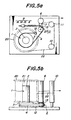
- FIG. 5 A fourth embodiment of the unwinding apparatus for the wire material under constant tension according to the invention is shown in Fig. 5.
- This apparatus has the same brake control means and brake adjusting means as in the third embodiment and is further provided with a deformation control means 5 for restricting the deformation in a portion of the brake band 4 contacting with the cylindrical portion 13.
- the deformation control means 5 is an iron plate 27 having a curvature along an outer circumference of the cylindrical portion 13, which is adhered to an outer side surface portion of the brake band 4 that contacts with the cylindrical portion 13. In this case, a time lag till the rotation of the dancer arm 7 reflects to the braking force is shortened to smoothly conduct the control of the braking force and improve the stability to disturbance.
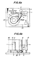
- FIG. 6 A fifth embodiment of the unwinding apparatus for the wire material under constant tension according to the invention is shown in Fig. 6.
- This apparatus is constructed by adding a second deformation control means 50 to the apparatus of the fourth embodiment.
- the second deformation control means 50 is a band-shaped iron plate 28 adhered to an outer side surface portion of the brake band 4 in a region ranging from the brake control means to the braking face 3, which develops the same effect as in the plate-shaped guide 26 in the third embodiment.
- the brake adjusting means is disposed on the brake energizing means 9 to adjust the energizing force of the brake energizing means 9.
- the brake adjusting means may be disposed on the fixed portion 12 for the brake band 4 so as to have a structure that the tension of the brake band 4 is adjusted by moving the position of the fixed portion 12 through, for example, a screw mechanism or the like.
- the brake adjusting means may be disposed on each of the brake energizing means 9 and the fixed portion 12 of the brake band 4.
- test conditions and evaluation parameters are as follows.
- the wire material After 70 kg of a wire material of a high carbon steel having a diameter of 0.3 mm is wound around a reel, the wire material is unwound from the reel at a rate of about 160 m/min, in which a value P of tension at an initial unwinding stage is set to 3.0 kg or 1.5 kg. Moreover, the setting of such an initial unwinding tension is carried out by adjusting the energizing force of the spring 8 through the nuts 15, 16 in the brake adjusting means.
- the apparatus of the third embodiment arranging the deformation control means 5 in a region ranging from the brake control means to the braking face 3 has an effect of making small the average tension difference A between the initial unwinding stage and the last unwinding stage.
- the change of the unwinding tension is small and the wire material can be always unwound under an approximately constant tension over a period ranging from the initial unwinding stage to the last unwinding stage irrespectively of the set value of unwinding tension.
- the apparatus according to the invention can be used as an unwinding apparatus in a twisting machine, in which poor twisting form or breakage due to the tension change can effectively be prevented.
Landscapes
- Tension Adjustment In Filamentary Materials (AREA)
Abstract
Description
| Third embodiment | Fourth embodiment | Fifth embodiment | Comparative Example | ||
| Average tension (kg) | initial stage | 3.00 | 3.00 | 3.00 | 3.00 |
| last stage | 3.20 | 3.20 | 3.15 | 3.46 | |
| | 7% (47) | 7% (47) | 5% (33) | 15% (100) | |
| Variation width (kg) | initial stage | 0.20 (133) | 0.15 (100) | 0.15 (100) | 0.15 (100) |
| last stage | 0.60 (200) | 0.15 (50) | 0.20 (67) | 0.30 (100) | |
| Converging time (second) | 10 (167) | 4 (67) | 5 (83) | 6 (100) |
| Third embodiment | Fourth embodiment | Fifth embodiment | Comparative Example | ||
| Average tension (kg) | initial stage | 1.50 | 1.50 | 1.50 | 1.50 |
| last stage | 1.71 | 1.69 | 1.68 | 1.93 | |
| | 14% (48) | 13% (45) | 12% (41) | 29% (100) | |
| Variation width (kg) | initial stage | 0.15 (75) | 0.10 (50) | 0.12 (60) | 0.20 (100) |
| last stage | 0.80 (200) | 0.20 (50) | 0.25 (63) | 0.40 (100) | |
| Converging time (second) | 12 (100) | 6 (50) | 9 (75) | 12 (100) |
Claims (6)
- Apparatus for unwinding a wire material under constant tension, which comprises a braking face (3) rotating together with a reel wound with a wire material, a brake band (4) contacting with the braking face (3), and a brake control means connected to an end of the brake band (4) for controlling tension of the brake band (4) to control braking force, characterized by a deformation control means (5) for restricting deformation in at least a part of the brake band (4).
- Apparatus as claimed in claim 1, characterized in that the deformation control means (5) is arranged at a position near to a contact starting point of the brake band (4) to the braking face (3).
- Apparatus as claimed in claim 1, characterized in that the deformation control means (5) is arranged at a position near to a connected portion of the brake band (4) to the brake control means.
- Apparatus as claimed in claim 1, characterized in that the deformation control means (5) is arranged at each of a position near to a contact starting point of the brake band (4) to the braking face (3) and a position near to a connected portion of the brake band (4) to the brake control means.
- Apparatus as claimed in any of claims 1 to 4, characterized in that the brake control means comprises a dancer arm (7) and a brake energizing means (9) for energizing the dancer arm (7) in a direction of raising contact pressure between the braking face (3) and the brake band (4), and the dancer arm (7) is provided with a dancer roll (6) and a cylindrical portion (13) coaxially arranged with respect to a rotating axis of the roll (6), and the brake band (4) is connected at its one end to the dancer arm (7) and arrives at the braking face (3) through the cylindrical portion (13), and the deformation control means (5) is arranged so as to restrict deformation of a portion of the brake band (4) contacting with the cylindrical portion (13).
- Apparatus as claimed in any of claims 1 to 5, characterized by further comprising a brake adjusting means for adjusting contact pressure between the brake band (4) and the braking face (3).
Applications Claiming Priority (2)
| Application Number | Priority Date | Filing Date | Title |
|---|---|---|---|
| JP10262198 | 1998-04-14 | ||
| JP10262198A JP3943235B2 (en) | 1998-04-14 | 1998-04-14 | Constant tension wire unwinding device |
Publications (3)
| Publication Number | Publication Date |
|---|---|
| EP0950629A2 true EP0950629A2 (en) | 1999-10-20 |
| EP0950629A3 EP0950629A3 (en) | 2000-04-19 |
| EP0950629B1 EP0950629B1 (en) | 2003-06-18 |
Family
ID=14332328
Family Applications (1)
| Application Number | Title | Priority Date | Filing Date |
|---|---|---|---|
| EP99302795A Expired - Lifetime EP0950629B1 (en) | 1998-04-14 | 1999-04-09 | Apparatus for unwinding wire material under constant tension |
Country Status (5)
| Country | Link |
|---|---|
| US (1) | US6315234B1 (en) |
| EP (1) | EP0950629B1 (en) |
| JP (1) | JP3943235B2 (en) |
| DE (1) | DE69908854T2 (en) |
| ES (1) | ES2200471T3 (en) |
Cited By (2)
| Publication number | Priority date | Publication date | Assignee | Title |
|---|---|---|---|---|
| GB2528885A (en) * | 2014-08-01 | 2016-02-10 | Texkimp Ltd | Tension strap |
| WO2017066178A1 (en) | 2015-10-13 | 2017-04-20 | Fives Machining Systems, Inc. | Passive tensioning system for composite material payout control |
Families Citing this family (4)
| Publication number | Priority date | Publication date | Assignee | Title |
|---|---|---|---|---|
| US6470656B2 (en) * | 2000-11-29 | 2002-10-29 | Illinois Tool Works Inc. | Film delivery system for prestretched film |
| KR20070050558A (en) * | 2005-11-11 | 2007-05-16 | 일진에이테크 주식회사 | Tensioning device of external element feeder for twisted pair device |
| DE102013005287A1 (en) * | 2013-03-27 | 2014-10-02 | Andreas Stihl Ag & Co. Kg | Hand-held implement and method for making a braking device of a hand-held implement |
| CN113998538A (en) * | 2021-12-10 | 2022-02-01 | 无锡统力电工有限公司 | Wrapping paper tape constant tension control device |
Family Cites Families (9)
| Publication number | Priority date | Publication date | Assignee | Title |
|---|---|---|---|---|
| US1946313A (en) | 1929-06-08 | 1934-02-06 | Gen Electric | Tensioning device |
| CH236864A (en) | 1943-06-18 | 1945-03-15 | Micafil Ag | Device for maintaining a permissible wire tension in coil winding machines. |
| US2562990A (en) | 1947-06-16 | 1951-08-07 | Ann R Peebles | Dereeling tension control |
| GB864989A (en) | 1958-03-07 | 1961-04-12 | Ass Elect Ind | Improvements relating to wire winding machines |
| US3076618A (en) | 1959-06-30 | 1963-02-05 | Charles F Van Hook | Wound material tensioning device |
| US3912191A (en) | 1974-04-18 | 1975-10-14 | Scandia Packaging Mach | Tape tensioning control assembly |
| DE4100173A1 (en) | 1991-01-05 | 1992-07-09 | Erich Kuehn | Creel tension regulator - has feeler with feedback to braking system when winding off from a bobbin |
| GB2267295A (en) | 1992-05-29 | 1993-12-01 | Rich City Limited | Dispenser for elongate material |
| KR970076641A (en) * | 1996-05-31 | 1997-12-12 | 배순훈 | Tape tension adjuster of tape recorder |
-
1998
- 1998-04-14 JP JP10262198A patent/JP3943235B2/en not_active Expired - Fee Related
-
1999
- 1999-03-30 US US09/280,850 patent/US6315234B1/en not_active Expired - Lifetime
- 1999-04-09 DE DE69908854T patent/DE69908854T2/en not_active Expired - Fee Related
- 1999-04-09 ES ES99302795T patent/ES2200471T3/en not_active Expired - Lifetime
- 1999-04-09 EP EP99302795A patent/EP0950629B1/en not_active Expired - Lifetime
Cited By (6)
| Publication number | Priority date | Publication date | Assignee | Title |
|---|---|---|---|---|
| GB2528885A (en) * | 2014-08-01 | 2016-02-10 | Texkimp Ltd | Tension strap |
| WO2017066178A1 (en) | 2015-10-13 | 2017-04-20 | Fives Machining Systems, Inc. | Passive tensioning system for composite material payout control |
| CN108473268A (en) * | 2015-10-13 | 2018-08-31 | 法孚机械加工系统股份有限公司 | Passive Tensioning System for Composite Release Control |
| EP3362391A4 (en) * | 2015-10-13 | 2018-12-26 | Fives Machining Systems, Inc. | Passive tensioning system for composite material payout control |
| RU2719038C2 (en) * | 2015-10-13 | 2020-04-16 | Файвз Машининг Системз, Инк. | Passive tensioning system for control of unwinding composite material |
| CN108473268B (en) * | 2015-10-13 | 2020-08-04 | 法孚机械加工系统股份有限公司 | Passive Tensioning System for Composite Release Control |
Also Published As
| Publication number | Publication date |
|---|---|
| DE69908854D1 (en) | 2003-07-24 |
| US6315234B1 (en) | 2001-11-13 |
| EP0950629B1 (en) | 2003-06-18 |
| EP0950629A3 (en) | 2000-04-19 |
| DE69908854T2 (en) | 2004-05-06 |
| JPH11292395A (en) | 1999-10-26 |
| ES2200471T3 (en) | 2004-03-01 |
| JP3943235B2 (en) | 2007-07-11 |
Similar Documents
| Publication | Publication Date | Title |
|---|---|---|
| US4120462A (en) | Method and device for controlling and/or regulating thread tension during winding of a textile coil | |
| CZ102198A3 (en) | Thread feeding device for elastic material | |
| EP0950629B1 (en) | Apparatus for unwinding wire material under constant tension | |
| KR100309578B1 (en) | Winding adjustment method | |
| MXPA06001926A (en) | Bobbin winding device. | |
| JPH08259057A (en) | Take-up device for continuous paper web | |
| US6240974B1 (en) | Apparatus for controlling the tension of catch selvage yarn in a weaving loom | |
| KR100624997B1 (en) | Self Calibrating Filament Tension Control Device | |
| JP2002145527A (en) | Winder for particularly sensitive winding materials | |
| KR960010191A (en) | Wire saw | |
| JP3696202B2 (en) | Self-compensating filament material tension control device using friction band | |
| EP2134481B1 (en) | Dual pivot ironing roll | |
| CN101228083B (en) | Method and device for winding a paper or board web | |
| US3092344A (en) | Strip tensioning apparatus | |
| JP4987462B2 (en) | Weft supply device | |
| EP1360132B1 (en) | Method and device for winding a paper or board web | |
| CS202751B1 (en) | Rewinding device of the wire electrode for the electrospark cutting device | |
| JP2006137512A (en) | Metal wire feeder | |
| US5390482A (en) | Apparatus and method for sending out linear material | |
| DE102006043641A1 (en) | winder | |
| EP1215152B1 (en) | An improved braking body for self-governing thread-braking devices in weft feeder apparatus and a process for its manufature | |
| JP2000354354A (en) | Winding device | |
| GB2104555A (en) | Wire tension apparatus | |
| JPH0824944A (en) | Winding device for metal plate or strip | |
| JP3161329B2 (en) | Guide pulley |
Legal Events
| Date | Code | Title | Description |
|---|---|---|---|
| PUAI | Public reference made under article 153(3) epc to a published international application that has entered the european phase |
Free format text: ORIGINAL CODE: 0009012 |
|
| AK | Designated contracting states |
Kind code of ref document: A2 Designated state(s): BE DE ES FR GB IT |
|
| AX | Request for extension of the european patent |
Free format text: AL;LT;LV;MK;RO;SI |
|
| PUAL | Search report despatched |
Free format text: ORIGINAL CODE: 0009013 |
|
| AK | Designated contracting states |
Kind code of ref document: A3 Designated state(s): AT BE CH CY DE DK ES FI FR GB GR IE IT LI LU MC NL PT SE |
|
| AX | Request for extension of the european patent |
Free format text: AL;LT;LV;MK;RO;SI |
|
| 17P | Request for examination filed |
Effective date: 20000417 |
|
| AKX | Designation fees paid |
Free format text: BE DE ES FR GB IT |
|
| 17Q | First examination report despatched |
Effective date: 20011001 |
|
| GRAH | Despatch of communication of intention to grant a patent |
Free format text: ORIGINAL CODE: EPIDOS IGRA |
|
| GRAH | Despatch of communication of intention to grant a patent |
Free format text: ORIGINAL CODE: EPIDOS IGRA |
|
| GRAA | (expected) grant |
Free format text: ORIGINAL CODE: 0009210 |
|
| AK | Designated contracting states |
Designated state(s): BE DE ES FR GB IT |
|
| REG | Reference to a national code |
Ref country code: GB Ref legal event code: FG4D |
|
| REF | Corresponds to: |
Ref document number: 69908854 Country of ref document: DE Date of ref document: 20030724 Kind code of ref document: P |
|
| REG | Reference to a national code |
Ref country code: ES Ref legal event code: FG2A Ref document number: 2200471 Country of ref document: ES Kind code of ref document: T3 |
|
| ET | Fr: translation filed | ||
| PLBE | No opposition filed within time limit |
Free format text: ORIGINAL CODE: 0009261 |
|
| STAA | Information on the status of an ep patent application or granted ep patent |
Free format text: STATUS: NO OPPOSITION FILED WITHIN TIME LIMIT |
|
| 26N | No opposition filed |
Effective date: 20040319 |
|
| PGFP | Annual fee paid to national office [announced via postgrant information from national office to epo] |
Ref country code: ES Payment date: 20090513 Year of fee payment: 11 |
|
| PGFP | Annual fee paid to national office [announced via postgrant information from national office to epo] |
Ref country code: FR Payment date: 20090417 Year of fee payment: 11 Ref country code: DE Payment date: 20090402 Year of fee payment: 11 |
|
| PGFP | Annual fee paid to national office [announced via postgrant information from national office to epo] |
Ref country code: BE Payment date: 20090401 Year of fee payment: 11 |
|
| PGFP | Annual fee paid to national office [announced via postgrant information from national office to epo] |
Ref country code: GB Payment date: 20090408 Year of fee payment: 11 |
|
| BERE | Be: lapsed |
Owner name: *BRIDGESTONE CORP. Effective date: 20100430 |
|
| GBPC | Gb: european patent ceased through non-payment of renewal fee |
Effective date: 20100409 |
|
| REG | Reference to a national code |
Ref country code: FR Ref legal event code: ST Effective date: 20101230 |
|
| PG25 | Lapsed in a contracting state [announced via postgrant information from national office to epo] |
Ref country code: DE Free format text: LAPSE BECAUSE OF NON-PAYMENT OF DUE FEES Effective date: 20101103 |
|
| PG25 | Lapsed in a contracting state [announced via postgrant information from national office to epo] |
Ref country code: GB Free format text: LAPSE BECAUSE OF NON-PAYMENT OF DUE FEES Effective date: 20100409 Ref country code: BE Free format text: LAPSE BECAUSE OF NON-PAYMENT OF DUE FEES Effective date: 20100430 |
|
| REG | Reference to a national code |
Ref country code: ES Ref legal event code: FD2A Effective date: 20110715 |
|
| PG25 | Lapsed in a contracting state [announced via postgrant information from national office to epo] |
Ref country code: ES Free format text: LAPSE BECAUSE OF NON-PAYMENT OF DUE FEES Effective date: 20110705 |
|
| PG25 | Lapsed in a contracting state [announced via postgrant information from national office to epo] |
Ref country code: ES Free format text: LAPSE BECAUSE OF NON-PAYMENT OF DUE FEES Effective date: 20100410 |
|
| PG25 | Lapsed in a contracting state [announced via postgrant information from national office to epo] |
Ref country code: FR Free format text: LAPSE BECAUSE OF NON-PAYMENT OF DUE FEES Effective date: 20100430 |
|
| PGFP | Annual fee paid to national office [announced via postgrant information from national office to epo] |
Ref country code: IT Payment date: 20140430 Year of fee payment: 16 |
|
| PG25 | Lapsed in a contracting state [announced via postgrant information from national office to epo] |
Ref country code: IT Free format text: LAPSE BECAUSE OF NON-PAYMENT OF DUE FEES Effective date: 20150409 |