EP3362131B1 - Mechanical ventilation with automatic control of patient's work of breathing using classical feedback control - Google Patents
Mechanical ventilation with automatic control of patient's work of breathing using classical feedback control Download PDFInfo
- Publication number
- EP3362131B1 EP3362131B1 EP16781104.1A EP16781104A EP3362131B1 EP 3362131 B1 EP3362131 B1 EP 3362131B1 EP 16781104 A EP16781104 A EP 16781104A EP 3362131 B1 EP3362131 B1 EP 3362131B1
- Authority
- EP
- European Patent Office
- Prior art keywords
- psv
- pob
- patient
- controller
- ventilator
- Prior art date
- Legal status (The legal status is an assumption and is not a legal conclusion. Google has not performed a legal analysis and makes no representation as to the accuracy of the status listed.)
- Active
Links
Images





Classifications
-
- A—HUMAN NECESSITIES
- A61—MEDICAL OR VETERINARY SCIENCE; HYGIENE
- A61M—DEVICES FOR INTRODUCING MEDIA INTO, OR ONTO, THE BODY; DEVICES FOR TRANSDUCING BODY MEDIA OR FOR TAKING MEDIA FROM THE BODY; DEVICES FOR PRODUCING OR ENDING SLEEP OR STUPOR
- A61M16/00—Devices for influencing the respiratory system of patients by gas treatment, e.g. ventilators; Tracheal tubes
- A61M16/021—Devices for influencing the respiratory system of patients by gas treatment, e.g. ventilators; Tracheal tubes operated by electrical means
- A61M16/022—Control means therefor
- A61M16/024—Control means therefor including calculation means, e.g. using a processor
- A61M16/026—Control means therefor including calculation means, e.g. using a processor specially adapted for predicting, e.g. for determining an information representative of a flow limitation during a ventilation cycle by using a root square technique or a regression analysis
-
- A—HUMAN NECESSITIES
- A61—MEDICAL OR VETERINARY SCIENCE; HYGIENE
- A61B—DIAGNOSIS; SURGERY; IDENTIFICATION
- A61B5/00—Measuring for diagnostic purposes; Identification of persons
- A61B5/08—Measuring devices for evaluating the respiratory organs
- A61B5/085—Measuring impedance of respiratory organs or lung elasticity
-
- A—HUMAN NECESSITIES
- A61—MEDICAL OR VETERINARY SCIENCE; HYGIENE
- A61B—DIAGNOSIS; SURGERY; IDENTIFICATION
- A61B5/00—Measuring for diagnostic purposes; Identification of persons
- A61B5/08—Measuring devices for evaluating the respiratory organs
- A61B5/087—Measuring breath flow
-
- A—HUMAN NECESSITIES
- A61—MEDICAL OR VETERINARY SCIENCE; HYGIENE
- A61B—DIAGNOSIS; SURGERY; IDENTIFICATION
- A61B5/00—Measuring for diagnostic purposes; Identification of persons
- A61B5/48—Other medical applications
- A61B5/4836—Diagnosis combined with treatment in closed-loop systems or methods
-
- A—HUMAN NECESSITIES
- A61—MEDICAL OR VETERINARY SCIENCE; HYGIENE
- A61M—DEVICES FOR INTRODUCING MEDIA INTO, OR ONTO, THE BODY; DEVICES FOR TRANSDUCING BODY MEDIA OR FOR TAKING MEDIA FROM THE BODY; DEVICES FOR PRODUCING OR ENDING SLEEP OR STUPOR
- A61M16/00—Devices for influencing the respiratory system of patients by gas treatment, e.g. ventilators; Tracheal tubes
- A61M16/0051—Devices for influencing the respiratory system of patients by gas treatment, e.g. ventilators; Tracheal tubes with alarm devices
-
- G—PHYSICS
- G16—INFORMATION AND COMMUNICATION TECHNOLOGY [ICT] SPECIALLY ADAPTED FOR SPECIFIC APPLICATION FIELDS
- G16H—HEALTHCARE INFORMATICS, i.e. INFORMATION AND COMMUNICATION TECHNOLOGY [ICT] SPECIALLY ADAPTED FOR THE HANDLING OR PROCESSING OF MEDICAL OR HEALTHCARE DATA
- G16H20/00—ICT specially adapted for therapies or health-improving plans, e.g. for handling prescriptions, for steering therapy or for monitoring patient compliance
- G16H20/40—ICT specially adapted for therapies or health-improving plans, e.g. for handling prescriptions, for steering therapy or for monitoring patient compliance relating to mechanical, radiation or invasive therapies, e.g. surgery, laser therapy, dialysis or acupuncture
-
- G—PHYSICS
- G16—INFORMATION AND COMMUNICATION TECHNOLOGY [ICT] SPECIALLY ADAPTED FOR SPECIFIC APPLICATION FIELDS
- G16H—HEALTHCARE INFORMATICS, i.e. INFORMATION AND COMMUNICATION TECHNOLOGY [ICT] SPECIALLY ADAPTED FOR THE HANDLING OR PROCESSING OF MEDICAL OR HEALTHCARE DATA
- G16H40/00—ICT specially adapted for the management or administration of healthcare resources or facilities; ICT specially adapted for the management or operation of medical equipment or devices
- G16H40/60—ICT specially adapted for the management or administration of healthcare resources or facilities; ICT specially adapted for the management or operation of medical equipment or devices for the operation of medical equipment or devices
- G16H40/63—ICT specially adapted for the management or administration of healthcare resources or facilities; ICT specially adapted for the management or operation of medical equipment or devices for the operation of medical equipment or devices for local operation
-
- A—HUMAN NECESSITIES
- A61—MEDICAL OR VETERINARY SCIENCE; HYGIENE
- A61B—DIAGNOSIS; SURGERY; IDENTIFICATION
- A61B5/00—Measuring for diagnostic purposes; Identification of persons
- A61B5/08—Measuring devices for evaluating the respiratory organs
- A61B5/0816—Measuring devices for examining respiratory frequency
-
- A—HUMAN NECESSITIES
- A61—MEDICAL OR VETERINARY SCIENCE; HYGIENE
- A61B—DIAGNOSIS; SURGERY; IDENTIFICATION
- A61B5/00—Measuring for diagnostic purposes; Identification of persons
- A61B5/72—Signal processing specially adapted for physiological signals or for diagnostic purposes
- A61B5/7235—Details of waveform analysis
- A61B5/725—Details of waveform analysis using specific filters therefor, e.g. Kalman or adaptive filters
-
- A—HUMAN NECESSITIES
- A61—MEDICAL OR VETERINARY SCIENCE; HYGIENE
- A61M—DEVICES FOR INTRODUCING MEDIA INTO, OR ONTO, THE BODY; DEVICES FOR TRANSDUCING BODY MEDIA OR FOR TAKING MEDIA FROM THE BODY; DEVICES FOR PRODUCING OR ENDING SLEEP OR STUPOR
- A61M16/00—Devices for influencing the respiratory system of patients by gas treatment, e.g. ventilators; Tracheal tubes
- A61M16/0003—Accessories therefor, e.g. sensors, vibrators, negative pressure
- A61M2016/0015—Accessories therefor, e.g. sensors, vibrators, negative pressure inhalation detectors
-
- A—HUMAN NECESSITIES
- A61—MEDICAL OR VETERINARY SCIENCE; HYGIENE
- A61M—DEVICES FOR INTRODUCING MEDIA INTO, OR ONTO, THE BODY; DEVICES FOR TRANSDUCING BODY MEDIA OR FOR TAKING MEDIA FROM THE BODY; DEVICES FOR PRODUCING OR ENDING SLEEP OR STUPOR
- A61M16/00—Devices for influencing the respiratory system of patients by gas treatment, e.g. ventilators; Tracheal tubes
- A61M16/0003—Accessories therefor, e.g. sensors, vibrators, negative pressure
- A61M2016/0027—Accessories therefor, e.g. sensors, vibrators, negative pressure pressure meter
-
- A—HUMAN NECESSITIES
- A61—MEDICAL OR VETERINARY SCIENCE; HYGIENE
- A61M—DEVICES FOR INTRODUCING MEDIA INTO, OR ONTO, THE BODY; DEVICES FOR TRANSDUCING BODY MEDIA OR FOR TAKING MEDIA FROM THE BODY; DEVICES FOR PRODUCING OR ENDING SLEEP OR STUPOR
- A61M16/00—Devices for influencing the respiratory system of patients by gas treatment, e.g. ventilators; Tracheal tubes
- A61M16/0003—Accessories therefor, e.g. sensors, vibrators, negative pressure
- A61M2016/003—Accessories therefor, e.g. sensors, vibrators, negative pressure with a flowmeter
-
- A—HUMAN NECESSITIES
- A61—MEDICAL OR VETERINARY SCIENCE; HYGIENE
- A61M—DEVICES FOR INTRODUCING MEDIA INTO, OR ONTO, THE BODY; DEVICES FOR TRANSDUCING BODY MEDIA OR FOR TAKING MEDIA FROM THE BODY; DEVICES FOR PRODUCING OR ENDING SLEEP OR STUPOR
- A61M2205/00—General characteristics of the apparatus
- A61M2205/33—Controlling, regulating or measuring
- A61M2205/3331—Pressure; Flow
-
- A—HUMAN NECESSITIES
- A61—MEDICAL OR VETERINARY SCIENCE; HYGIENE
- A61M—DEVICES FOR INTRODUCING MEDIA INTO, OR ONTO, THE BODY; DEVICES FOR TRANSDUCING BODY MEDIA OR FOR TAKING MEDIA FROM THE BODY; DEVICES FOR PRODUCING OR ENDING SLEEP OR STUPOR
- A61M2205/00—General characteristics of the apparatus
- A61M2205/50—General characteristics of the apparatus with microprocessors or computers
-
- A—HUMAN NECESSITIES
- A61—MEDICAL OR VETERINARY SCIENCE; HYGIENE
- A61M—DEVICES FOR INTRODUCING MEDIA INTO, OR ONTO, THE BODY; DEVICES FOR TRANSDUCING BODY MEDIA OR FOR TAKING MEDIA FROM THE BODY; DEVICES FOR PRODUCING OR ENDING SLEEP OR STUPOR
- A61M2205/00—General characteristics of the apparatus
- A61M2205/50—General characteristics of the apparatus with microprocessors or computers
- A61M2205/52—General characteristics of the apparatus with microprocessors or computers with memories providing a history of measured variating parameters of apparatus or patient
-
- A—HUMAN NECESSITIES
- A61—MEDICAL OR VETERINARY SCIENCE; HYGIENE
- A61M—DEVICES FOR INTRODUCING MEDIA INTO, OR ONTO, THE BODY; DEVICES FOR TRANSDUCING BODY MEDIA OR FOR TAKING MEDIA FROM THE BODY; DEVICES FOR PRODUCING OR ENDING SLEEP OR STUPOR
- A61M2230/00—Measuring parameters of the user
- A61M2230/04—Heartbeat characteristics, e.g. ECG, blood pressure modulation
- A61M2230/06—Heartbeat rate only
-
- A—HUMAN NECESSITIES
- A61—MEDICAL OR VETERINARY SCIENCE; HYGIENE
- A61M—DEVICES FOR INTRODUCING MEDIA INTO, OR ONTO, THE BODY; DEVICES FOR TRANSDUCING BODY MEDIA OR FOR TAKING MEDIA FROM THE BODY; DEVICES FOR PRODUCING OR ENDING SLEEP OR STUPOR
- A61M2230/00—Measuring parameters of the user
- A61M2230/40—Respiratory characteristics
-
- A—HUMAN NECESSITIES
- A61—MEDICAL OR VETERINARY SCIENCE; HYGIENE
- A61M—DEVICES FOR INTRODUCING MEDIA INTO, OR ONTO, THE BODY; DEVICES FOR TRANSDUCING BODY MEDIA OR FOR TAKING MEDIA FROM THE BODY; DEVICES FOR PRODUCING OR ENDING SLEEP OR STUPOR
- A61M2230/00—Measuring parameters of the user
- A61M2230/40—Respiratory characteristics
- A61M2230/42—Rate
-
- A—HUMAN NECESSITIES
- A61—MEDICAL OR VETERINARY SCIENCE; HYGIENE
- A61M—DEVICES FOR INTRODUCING MEDIA INTO, OR ONTO, THE BODY; DEVICES FOR TRANSDUCING BODY MEDIA OR FOR TAKING MEDIA FROM THE BODY; DEVICES FOR PRODUCING OR ENDING SLEEP OR STUPOR
- A61M2230/00—Measuring parameters of the user
- A61M2230/40—Respiratory characteristics
- A61M2230/43—Composition of exhalation
- A61M2230/432—Composition of exhalation partial CO2 pressure (P-CO2)
-
- A—HUMAN NECESSITIES
- A61—MEDICAL OR VETERINARY SCIENCE; HYGIENE
- A61M—DEVICES FOR INTRODUCING MEDIA INTO, OR ONTO, THE BODY; DEVICES FOR TRANSDUCING BODY MEDIA OR FOR TAKING MEDIA FROM THE BODY; DEVICES FOR PRODUCING OR ENDING SLEEP OR STUPOR
- A61M2230/00—Measuring parameters of the user
- A61M2230/40—Respiratory characteristics
- A61M2230/46—Resistance or compliance of the lungs
Definitions
- the following relates generally to the mechanical ventilation arts, respiratory health arts, and related arts.
- Mechanical ventilators are life-saving machines that help patients with impaired respiratory drive, or lack of respiratory drive, on a temporary or long term basis. In both cases, the level of respiratory support strongly impacts patient outcome. It is estimated that about 1-in-5 patients who receive mechanical ventilation develop some form of ventilator-related lung injury attributable to the ventilator providing too much support. Another problem with the providing too much ventilator support is that the patient may become overly dependent on the ventilator machine, which can lead to more difficult wean-off from the ventilator and longer recovery time for the patient. On the other hand, if the ventilator provides too little support, then the patient overexerts to breathe producing detrimental patient stress. Too little ventilation support can also lead to insufficient respiration and potential adverse conditions such as hypoxia.
- CMV continuous mandatory ventilation
- the ventilator initiates mandatory breaths at a programmed respiration rate, and each mandatory breath is driven to a pre-set inflation volume by action of the mechanical ventilator. This ensures adequate ventilation, but it is difficult to later wean the patient off the ventilator as CMV does not support any spontaneous respiration effort by the patient.
- PSV Pressure Support Ventilation
- the ventilator controller detects the onset of spontaneous inspiration as a decrease in airway pressure or an abrupt increase in air flow. The ventilator then applies pressure at a PSV pressure setting to support the patient's spontaneous inhalation effort.
- the patient controls respiration rate and inflation volume, with the mechanical ventilator being limited to providing pressure support at the PSV pressure setting to assist the spontaneous breaths. PSV is thus well-suited to providing ventilator assistance for a spontaneously breathing patient.
- PSV When PSV is used alone, the patient initiates all breaths. This is beneficial to encourage the patient's respiratory effort, but PSV cannot provide effective ventilation if the patient fails to spontaneously initiate breaths at a sufficient rate.
- PSV may be combined with an intermittent mandatory ventilation (IMV) mode that triggers ventilator-driven (i.e. mandatory) breaths if the spontaneous breaths alone are determined by the ventilator to provide insufficient ventilation for the patient.
- IMV intermittent mandatory ventilation
- Typical ventilator settings of a ventilator operating in a PSV or PSV/IMV mode include the PSV pressure setting, one or more trigger parameters (specifying how the ventilator detects spontaneous breaths), one or more mandatory breath cycling parameters (controlling timing of IMV-initiated mandatory breaths), and fraction of inspired oxygen (FiO 2 , for oxygenated patients).
- These ventilator settings are prescribed by the physician.
- airway pressure and flow, fraction or percent of respired carbon dioxide (CO 2 , via capnography, e.g. end-tidal CO 2 or et CO 2 ), heart rate, respiratory rate, peripheral capillary oxygen saturation (SpO 2 ), and/or so forth are monitored.
- the prescribed ventilator settings may be adjusted based on the patient's current condition as indicated by the various physiological measurements.
- the patient's condition may change significantly between successive physician visits. This can lead to the patient being mechanically ventilated under significantly non-optimal ventilator settings until the next physician visit. Ventilation using non-optimal ventilator settings, in turn, enhances the likelihood of ventilator-related lung injury.
- inspiratory muscle training using flow/volume control can be based on patient monitored power of breathing (or work of breathing). Actual or estimated patient power of breathing (or work of breathing) is first established.
- a target power of breathing or work of breathing is determined, either by the user or automatically by the ventilator (following software derived values for power of breathing/work of breathing).
- the target power of breathing or work of breathing is communicated to the ventilator to impose an inspiratory muscle training stimulus so that the patient performs a strength training regimen in accordance with the invention.
- the inspiratory strength training stimulus involves adjusting ventilator settings (either manually or automatically) to manipulate the flow and/or volume of breathing gases provided to the patient so that the patient is forced to breathe at the target power of breathing.
- the patient's estimated or actual power of breathing (or work of breathing) is constantly monitored and the target power of breathing (or work of breathing) is dynamically established in the ventilator for personalized inspiratory muscle training.
- pressure support ventilation (PSV) or a similar mode of ventilatory support providing inspiratory assist pressure, is automatically up- and down-regulated by a closed-loop ventilator to maintain power of breathing in a normal range for example to treat a patient.
- the closed-loop ventilator When the patient is to undergo inspiratory muscle strength training in accordance with the invention, power of breathing is temporarily maintained at a higher range than that of normal range. This is accomplished by having the closed-loop ventilator down-regulate the inspiratory assist pressure, causing power of breathing to increase to a higher range. Once established at this higher range, the closed-loop ventilator automatically regulates inspiratory assist pressure to maintain the increased power of breathing. When the exercise/training session is completed, the closed-loop ventilator automatically increases inspiratory assist pressure to restore power of breathing to back down to normal treatment levels.
- the method for inspiratory muscle strength training comprises use of a mathematical model, such as a neural network, wherein the neural network imposes negative pressures for the patient based upon input data (provided either by the user or derived from a ventilator or respiratory monitor), wherein the input data includes at least one of the following parameters: work of breathing, power of breathing, the airway pressure, flow, airway volume, carbon dioxide flow, and pulse oximeter plethysmogram waveforms normally collected by a respiratory monitor, including but not limited to tidal volume, breathing frequency, peak inspiratory pressure (PIP), inspiratory time, P0.01, trigger time, trigger depth, respiratory system resistance, respiratory compliance, end-tidal carbon dioxide, variations in the pulse oximeter plethysmogram, and the concavity/convexity of the pressure waveform,wherein the inspiratory training pressure is provided as an output variable.
- a mathematical model such as a neural network
- the neural network imposes negative pressures for the patient based upon input data
- Chbat et al., WO 2014/207623 A2 published December 31, 2014 discloses a method for non-invasive of intra-pleural pressure and computation of Work of Breathing based on an estimation of intra-pleural pressure.
- Chbat et al. U.S. Pub. No. 2015/0059754 published March 5, 2015 discloses an improvement in which the patient's Power of Breathing (PoB) is estimated in real-time and, if different from a physician-prescribed PoB, one or more ventilator setting adjustments are made (optionally automatically) based on the identified PoB difference.
- the ventilator setting adjustments may include, for example, changing settings such as tidal volume, respiratory rate, pressure readings, airflow, or so forth, and/or may also include changes to an operating mode of the ventilator.
- the approach of Chbat et al. is generally applicable to ventilator modes including but not limited to: volume controlled continuous mandatory ventilation, volume controlled intermittent mandatory ventilation, pressure controlled continuous mandatory ventilation, pressure controlled intermittent mandatory ventilation, continuous spontaneous ventilation, high frequency ventilation systems, or so forth.
- a single input, single output (SISO) closed loop controller for controlling a mechanical ventilator configured to provide mechanical ventilation to a patient in a PSV or PSV/IMV mode in accordance with a PSV pressure setting.
- the closed-loop controller comprises: a PoB or WoB estimator configured to generate a signal representing PoB or WoB of the patient; an error calculator configured to compute an error signal E ( s ) as a difference between the signal representing PoB or WoB of the patient and a set point value; and a controller having a controller transfer function C ( s ) and configured to generate the PSV pressure setting as the product C ( s ) E ( s ) .
- a closed loop controller for controlling a mechanical ventilator configured to provide mechanical ventilation to a spontaneously breathing patient.
- the closed-loop controller comprises: a PoB or WoB estimator configured to generate a PoB or WoB signal for the patient; an error calculator configured to compute an error signal E ( s ) as a difference between the PoB or WoB signal and a set point PoB or WoB value; a controller having a controller transfer function C(s) and configured to input a pressure support ventilation (PSV) control signal equal to the product C ( s ) E ( s ) to the mechanical ventilator to control the mechanical ventilation provided to the spontaneously breathing patient; and a patient adaptation component comprising an electronic device programmed to fit parameters of a model of a controlled mechanical ventilation system comprising a ventilator and a spontaneously breathing patient ventilated by the mechanical ventilator under control of the closed loop controller to data comprising the PoB or WoB signal and the PSV control signal generated by the operating closed loop controller and to adjust parameters
- a closed loop control method for controlling mechanical ventilation provided by a mechanical ventilator to a spontaneously breathing patient.
- the closed-loop control method comprises: measuring a PoB or WoB signal for the patient being provided mechanical ventilation; computing an error signal as a difference between the measured PoB or WoB signal and a set point PoB or WoB value; and setting pressure support of the mechanical ventilation to a control signal computed as a product of a controller transfer function and the error signal.
- One advantage resides in providing improved automated ventilator control for mechanically ventilated spontaneously breathing patients.
- Another advantage resides in providing such automated ventilator control with physician-prescribed constraints having physiological bases.
- Another advantage resides in providing such automated ventilator control that is adaptive to changing patient condition.
- Another advantage resides in providing such automated ventilator control that is robust against noise and system disturbances.
- Another advantage resides in providing such automated ventilator control with zero steady state error.
- a given embodiment may provide none, one, two, more, or all of the foregoing advantages, and/or may provide other advantages as will become apparent to one of ordinary skill in the art upon reading and understanding the present disclosure.
- an embodiment forms part of the invention only if it falls within the scope of claim 1.
- a mechanically ventilated spontaneously breathing patient is ventilated using pressure support ventilation (PSV), with or without intermittent mandatory ventilation (IMV).
- PSV pressure support ventilation
- IMV intermittent mandatory ventilation
- the mechanical ventilator detects the onset of a spontaneous breath and provides pressure support for the breath in accord with a PSV pressure setting.
- the pressure support waveform may take various forms, e.g. a square wave of amplitude equal to the PSV pressure setting, or an increasing pressure ramp in which the ramp peak equals the PSV pressure setting (or the ramp average or other ramp amplitude characteristic equals the PSV pressure setting), or a decreasing pressure ramp, parabolic pressure waveform, or so forth.
- the ventilator settings of the applied PSV or PSV/IMV ventilation mode may also include one or more trigger parameters, such as (by way of illustration) a negative pressure threshold wherein airway pressure falling below this threshold is detected as onset of a spontaneous breath, and/or an air flow threshold wherein airway air flow rate above this threshold is detected as onset of a spontaneous breath. If the patient is being oxygenated, the fraction of inspired oxygen (FiO 2 ) is another ventilator setting. If a PSV/IMV mode is being applied, then one or more IMV mandatory breath cycle settings are also provided. Still further ventilator settings may be provided, such as a maximum inflation volume or other safety-related limits.
- the PSV pressure setting is the primary parameter for effectively tailoring the PSV or PSV/IMV ventilation to elicit the desired work of breathing (WoB) or power of breathing (PoB) from the patient. Accordingly, in embodiments disclosed herein the PSV pressure setting is the only automatically controlled ventilator setting.
- the PSV pressure setting can be controlled based on measured WoB or PoB using a classical feedback control system in which the combination of the ventilator and the patient, along with the PoB or WoB estimator, is treated as the controlled system having a transfer function G (s) which is controlled by a controller having a transfer function C ( s ) .
- a transfer function is the ratio of the output to the input of a system (or sub-system), and a transfer function is represented herein in the (complex) frequency domain by its Laplace transform, i.e.
- the output of the controlled ventilator/patient system is a WoB or PoB signal
- the control input to the controlled ventilator/patient system is the PSV pressure setting.
- the WoB or PoB signal is represented herein as PoB(s) in the s-domain, that is, in illustrative examples presented herein the power of breathing (PoB) is employed.
- the PoB is power per unit time (e.g. having units of Joules/sec)
- WoB is power per breath (e.g. having units of Joules/breath).
- Either PoB or WoB can be used as the output signal of the controlled ventilator/patient system, but PoB has an advantage in that it does not depend on the generally non-uniform breath interval of a spontaneously breathing patient. In a suitable approach, if WoB is measured it may be converted to PoB using the breath time interval.
- the controller transfer function C ( s ) can be designed so that the closed loop transfer function is stable for a wide range of patients.
- the controller is adaptive.
- the controller transfer function C ( s ) is then adjusted, if needed, in order to ensure the closed loop system transfer function C s G s 1 + C s G s is stable for the current patient. This adaptation can be updated periodically to ensure the controller remains a stable.
- a respiratory therapy device includes a mechanical ventilator 10 that provides mechanical ventilation to a patient 12 via air hoses 14.
- the mechanical ventilator 10 is of any design capable of delivering mechanical ventilation in a Pressure Support Ventilation (PSV) or pressure support ventilation/intermittent mandatory ventilation (PSV/IMV) mode.
- the mechanical ventilator 10 may include various ancillary components such as an air filter, a medical oxygen supply to deliver a prescribed fraction of inspired oxygen (FiO 2 ), a humidifier, or so forth.
- the mechanical ventilator includes a controller, diagrammatically shown and labeled as a "mode" controller 16, which is a microprocessor or microcontroller and ancillary sensors and electronics programmed to operate the mechanical ventilator 10 in a PSV or PSV/IMV mode based on sensor data 18 such as an airway pressure P aw ( t ) measured by an airway pressure gauge, and airway air flow V ⁇ ( t ) measured by an airway air flow sensor.
- mode controller 16 is a microprocessor or microcontroller and ancillary sensors and electronics programmed to operate the mechanical ventilator 10 in a PSV or PSV/IMV mode based on sensor data 18 such as an airway pressure P aw ( t ) measured by an airway pressure gauge, and airway air flow V ⁇ ( t ) measured by an airway air flow sensor.
- the sensor data 18 may include various other physiological parameters may also be monitored by suitable sensors such as heart rate (HR), respiratory rate (RR), end-tidal carbon dioxide (et CO 2 , measured by capnography), or so forth. These data may be displayed on a display component 19 of the mechanical ventilator 10, and/or on a bedside patient monitor or so forth.
- the mode controller 16 detects the onset of spontaneous inspiration (i.e. start of a breath intake), for example as an abrupt decrease in airway pressure P aw ( t ) and/or an abrupt increase in air flow V ⁇ ( t ). Thresholds for this detection may be physician-prescribed parameters or default values of the mechanical ventilator 10.
- the mechanical ventilator 10 Upon detection of onset of a spontaneous breath intake, the mechanical ventilator 10 applies pressure at a PSV pressure setting to support the patient's spontaneous inhalation effort.
- This pressure may be provided in accord with a prescribed or default pressure support-over-time profile, e.g. a square wave (pressure support at a constant magnitude over the breath) or with some ramp or other profile feature(s).
- the pressure support may be terminated after a fixed time interval, or may be terminated based on detection of the end of the patient's spontaneous breath intake effort.
- the mode controller 16 If the mode controller 16 is implementing a PSV/IMV mode, then in addition to providing the foregoing pressure support for spontaneous breaths, the mode controller 16 additionally triggers ventilator-driven (i.e. mandatory) breaths if the spontaneous breaths alone do not provide a prescribed or default minimum level of ventilation for the patient (which may be measured based on total number of breaths, and/or inspired air volume, or so forth).
- the mode controller 16 implements a PSV/IMV mode in which the intermittent mandatory ventilation is provided in accordance with a synchronized intermittent mandatory ventilation (SIMV) approach in which the timing of any mandatory breaths is synchronized with the spontaneous breaths.
- SIMV synchronized intermittent mandatory ventilation
- the PSV or PSV/IMV mode may be implemented in the respiratory therapy device of FIGURE 1 without modification from conventional PSV or PSV/IMV mode mechanical ventilation.
- the physician may prescribe various trigger thresholds or other PSV or PSV/IMV mode parameters as is conventional in the respiratory therapy arts, and the mechanical ventilator 10 implements the PSV or PSV/IMV mode in a conventional manner.
- the respiratory therapy device of FIGURE 1 differs from a conventional mechanical ventilation device in that it provides an "outer" control loop, that is, a control loop that is "outside" of the control loop of the mode controller 16.
- This outer control loop is referred to hereinafter as a single-input, single-output (SISO) closed loop feedback control system or using similar phraseology.
- the SISO control loop employs classical feedback control using a controller 20 having a transfer function designated herein without loss of generality as C ( s ).
- the SISO control loop receives as input a physician-prescribed power of breathing (PoB) set point 22, which is the desired respiratory effort for the patient 12.
- the controller 20 outputs a control signal 24 in the form of a PSV setting 24 that is input to the mechanical ventilator 10.
- the ventilator/patient system 26 comprising the mechanical ventilator 10 and the patient 12 operates in accord with the PSV or PSV/IMV settings prescribed by the physician but with the PSV setting equal to the control signal 24.
- a PoB estimator 30 estimates the PoB exerted by the patient 12 based on sensor data 32.
- the PoB estimator 30 outputs a measured PoB signal 34 which is compared with the set point PoB 22 by an error calculator 36 configured to compute an error signal E ( s ) as a difference between the PoB signal 34 and the set point PoB value 22.
- This error signal E(s) is input to the PSV pressure setting controller 20 which computes the PSV setting 24 as C ( s ) E ( s ), that is, the product of the controller transfer function C ( s ) of the controller 20 and the error signal E ( s ) .
- the physician may optionally prescribe lower and upper limits 38 on the PSV setting 24, so that if the product C ( s ) E ( s ) goes below the lower limit the control signal is set to the lower limit, and similarly if the product C ( s ) E ( s ) goes above the upper limit the control signal is set to the upper limit. Reaching these (or optionally other) physician-prescribed upper or lower limits optionally also sets off an alarm, e.g. a warning displayed on the display component 19 of the mechanical ventilator 10 that the pressure support provided by the mechanical ventilator 10 has reached (or is approaching) an upper or lower limit.
- the lower and upper PSV limits 38 may be physician-prescribed values, or may be default limits of the respiratory therapy device. In another embodiment, both are contemplated, e.g. default upper and lower limits and additionally the physician can choose to prescribe a narrower limit (e.g. a lower upper limit than the default, or a higher lower limit than the default).
- the respiratory muscle pressure P mus ( t ) is measured using an esophageal pressure measurement employing a balloon that is inserted inside the esophagus of the patient 12 and outputs sensor data 32 comprising measured esophageal pressure P es ( t ) .
- the esophageal pressure is assumed to be a good proxy for the pleural pressure and is used, in conjunction with an estimate of respiratory system chest wall compliance C rs , to compute the WoB via the so-called Campbell diagram or, equivalently, via explicit computation of P mus ( t ) and then of PoB.
- respiratory muscle pressure P mus ( t ) is estimated using an Equation of Motion of the Lungs, e.g.
- P aw t R rs V ⁇ t + 1 C rs V t + P mus t + P 0
- P aw ( t ) the measured airway pressure
- V ⁇ ( t ) the measured air flow
- V ( t ) the respired air volume
- R rs the respiratory system resistance
- P 0 is a constant term to account for the pressure at the end of expiration.
- the sensor inputs 32 to the PoB estimator 30 include airway pressure P aw ( t ) and flow V ⁇ ( t ) .
- the flow-interrupter technique also called End Inspiratory Pause (EIP)
- EIP End Inspiratory Pause
- R rs and C rs or E rs
- Equation (1) may be solved to simultaneously determine P mus ( t ) , R rs , and C rs (or E rs ) .
- Equation (1) is underdetermined since for N samples there are N + 2 unknowns (the values of P mus ( t ) for each of the N samples plus R rs and C rs ) .
- a piecewise approximation of P mus ( t ) or other approach for reducing the number of unknowns is contemplated to make the simultaneous solution tractable.
- PSV ( s ) is the control input 24 (i.e. the PSV setting)
- PoB(s) is the POB signal 34 output by the PoB estimator 30.
- the transfer function G s PoB s PSV s is, in general, different from patient to patient, and also depends on the patient's current respiratory system condition and general health, state of consciousness, or so forth. Furthermore, the transfer function G ( s ) may depend on the physician-prescribed or default settings of the PSV or PSV/IMV mode currently in force, such as the trigger settings for triggering pressure support. (As an example, if the operational trigger setting results in some delay in the initiation of pressure support this can lead to increased patient effort and hence higher PoB).
- G ( s ) can vary significantly, and the transfer function C ( s ) of the controller 20 is preferably designed to provide large operational margins for G ( s ) that encompass a wide range (and preferably all) of the credible variants of the system transfer function G ( s ) .
- a representative database is generated for "training" patients under mechanical ventilation. For each training patient, input PSV and output PoB data are collected for different PSV settings. These training data are used for optimizing the controller C(s).
- an illustrative design approach for designing the controller 20, and more particularly its transfer function C ( s ), is described.
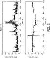
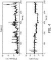
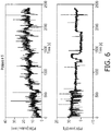
- Table 1 lists the age, gender, height, weight, and disease/medical issue of each of these five training patients.
- Table 1 - training patients Patient # Age Gender Height Weight Disease, Issue P1 79 Male 68 inches 70 kg Ischemic gut P2 70 Female 60 inches 60 kg Sepsis, COPD P3 55 Male 67 inches 71 kg Hemopneumothorax P4 54 Male 67 inches 76 kg Sepsis (candidemia) P5 77 Male 70 inches 71 kg Bilateral Pneumonia
- each training patient was mechanically ventilated under PSV mode and during the ventilation, the level of pressure support was changed a few times. Also, during the ventilation time, the esophageal pressure is measured using an esophageal balloon. The respiratory muscle pressure P mus ( t ) was calculated using an estimated value of chest wall compliance, and the PoB was calculated from P mus ( t ).
- P mus ( t ) was calculated using an estimated value of chest wall compliance
- the PoB was calculated from P mus ( t ).
- the top plot shows the measured PoB signal 34 (in units of Joules/min) and the bottom plot shows the input PSV setting 24 (in units of cmH 2 O), again operating in open loop without use of the controller 20.
- the level of noise or disturbance in the ventilator/patient/PoB estimator system is high, and this noise information was taken into account in the design of the control system.
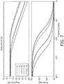
- Table 2 lists the fitted values for K p and ⁇ for the ventilator/patient system for each of the five patients P1-P5.
- FIGURE 7 shows the Bode plots of the five open loop ventilator/patient systems.
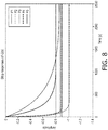
- FIGURE 8 shows the time-domain step responses of the five open loop ventilator/patient systems. It is noteworthy that although these five ventilator/patient systems are very different in terms of time responses ( FIGURE 8 ), the DC gain K p of all five ventilator/patient systems are within a relatively small range between -0.80 and -1.05. This simplifies the gain selection for the controller transfer function C ( s ).
- Table 2 - System models for training ventilator/patient systems Patient # K p (DC gain) ⁇ (Time constant) P1 -0.90 33.3 P2 -0.90 27.7 P3 -0.87 491 P4 -1.02 50.6 P5 -0.81 203.5
- FIGURE 9 design of the controller transfer function C ( s ) based on the five ventilator/patient training systems is described. From the training data of FIGURES 2-6 , it is seen that the noise in the system is at a relatively low frequency. This motivates providing a non-zero, positive-valued pole at relatively low frequency, e.g. a non-zero, positive pole P ⁇ 200 sec -1 in some contemplated embodiments. Furthermore, the controller 20 should provide zero steady state error - this motivates placing another pole at the origin of the s-plane.
- FIGURE 9 shows the Bode plots of the closed-loop SISO system transfer functions L ( s ) for the controller C(s) of Equation (4) operating with the ventilator/patient systems of FIGURES 7 and 8 .
- Table 3 lists the gain margin (GM), phase margin (PM), and bandwidth (BW) achieved for each patient by the designed controller. Table 3 - margins of stability Patient # GM (dB) PM (Deg) BW (rad/sec) P1 29 76 (.00178) P2 28 77.1 (.00177) P3 16.8 47.1 (.00142) P4 23.3 73 (.00199) P5 19.3 64 (.00153)
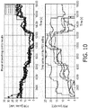
- Equation (4) was simulated on the ventilator/patient models of Equation (2) and Table 2.
- the PSV level was updated every 5 minutes, with the PSV updates discretized to a minimum PSV level change of 1 cmH 2 O up or down.
- the maximum allowable PSV change step was 5 cmH 2 O (that is, the largest change in PSV setting at a single 5 minute interval).
- the PSV lower and upper limits 38 were 0 cmH 2 O and 25 cmH 2 O, respectively.
- FIGURE 10 shows the simulation results, which exhibited stable responses for all five ventilator/patient systems.
- an initial or starting PSV setting is suitably chosen, e.g. prescribed by the physician (preferably) or a default initial PSV setting may be used.
- the controller 20 then adjusts the PSV setting 24 based on accumulating history of the PoB signal 34 and thereby accumulating error history E ( s ) .
- controller represented by the transfer function C ( s ) of Equation (3) is an illustrative example which has been demonstrated to work well for the representative ventilator/patient systems used in the training.
- Other controller designs are contemplated. For example, adding a zero to the controller transfer function is contemplated to provide a faster transient response.
- Another contemplated variant is to add a second, higher frequency positive pole, e.g. at a value greater than 200 sec -1 , which could beneficially suppress higher frequency noise if present.
- the respiratory therapy device of FIGURE 1 using a controller transfer function in accord with Equation (3) has been shown to provide large margins for the five training ventilator/patient systems.
- additional stability can be obtained by constructing the controller 20 to be an adaptive controller. This may be useful, for example, if the controller 20 is to be used with a wider range of patient types (e.g. both infants and elderly patients), or with a number of different types of mechanical ventilators, patient accessories, or so forth.
- FIGURE 11 Diagrammatically indicated in FIGURE 11 are the controller 20 (grouped with the error calculator 36 as a unit in FIGURE 11 ), the physician-prescribed PoB set point 22, and the estimated PoB signal 34. Also indicated in FIGURE 11 is the PSV setting 24 output by the controller 20.
- the start of patient ventilation is indicated in FIGURE 1 by a "start" block 50.
- the variant of FIGURE 11 adds a patient adaptation component including blocks 52, 54, 56, 60. After ventilator startup 50, the SISO closed-loop feedback controller runs for a pre-set time (two hours, i.e.
- a delay block 52 diagrammatically shows implementation of this initial delay. During this delay, PoB and PSV setting data are collected and stored in operation 54. When the pre-set time interval (e.g. 120 min) has passed, flow passes to a ventilator/patient model update operation 56, which updates G ( s ) .
- this can be done by fitting the first-order model of Equation (2) to optimize K p and ⁇ respective to the collected (PSV(t), PoB(t)) data after transforming PSV(t) and PoB(t), respectively, into the s-domain using the Laplace transform.
- the resulting updated G (s) 58 is input to a controller update operation 60 which updates the controller transfer function C ( s ) to provide large-margin control of the ventilator/patient represented by the updated G ( s ) 58.
- the outer loop components may be implemented as one or more electronic components separate from the mechanical ventilator 10.
- the controller 20, PoB estimator 30, and error calculator 36 are constructed as a unitary add-on control box including a microprocessor or microcontroller and ancillary circuitry, and having a port outputting the PSV setting 24 via a cable to the mechanical ventilator 10 and having an input port receiving the esophageal pressure reading 32 from an esophageal catheter.
- the outer loop components can be integrated with the mechanical ventilator 10.
- the controller 20, PoB estimator 30, and error calculator 36 are suitably implemented on the same microprocessor that is programmed to implement the mode controller 16.
- the PSV setting 24 is conveyed to the mode controller 16 in software, e.g. as an argument of a call function or so forth, and the mechanical ventilator 10 is modified only in providing an input port to receive the esophageal pressure reading 32.
- the PoB signal 34 is calculated using an Equation of Motion of the Lungs (e.g.
- the outer loop can be implemented on the same microprocessor of the mechanical ventilator 10 which implements the mode controller 16 without adding any additional input or output ports or other hardware.
- the outer loop may be implemented as a non-transitory storage medium storing instructions executable on the microprocessor of the mechanical ventilator 10 and/or on a separate microprocessor to perform the disclosed control functionality (optionally with a adaptation as described with reference to FIGURE 11 ).
- the non-transitory storage medium may, for example, comprise a flash memory or other solid state electronic storage device or component, a magnetic disk or other magnetic storage device or component, an optical disk or other optical storage device or component, or so forth.
Landscapes
- Health & Medical Sciences (AREA)
- Life Sciences & Earth Sciences (AREA)
- Engineering & Computer Science (AREA)
- Biomedical Technology (AREA)
- Public Health (AREA)
- General Health & Medical Sciences (AREA)
- Medical Informatics (AREA)
- Pulmonology (AREA)
- Veterinary Medicine (AREA)
- Heart & Thoracic Surgery (AREA)
- Animal Behavior & Ethology (AREA)
- Surgery (AREA)
- Pathology (AREA)
- Biophysics (AREA)
- Physics & Mathematics (AREA)
- Molecular Biology (AREA)
- Epidemiology (AREA)
- Primary Health Care (AREA)
- Physiology (AREA)
- Emergency Medicine (AREA)
- Anesthesiology (AREA)
- Hematology (AREA)
- Business, Economics & Management (AREA)
- General Business, Economics & Management (AREA)
- Urology & Nephrology (AREA)
- Nuclear Medicine, Radiotherapy & Molecular Imaging (AREA)
- Measurement Of The Respiration, Hearing Ability, Form, And Blood Characteristics Of Living Organisms (AREA)
Applications Claiming Priority (2)
| Application Number | Priority Date | Filing Date | Title |
|---|---|---|---|
| US201562240147P | 2015-10-12 | 2015-10-12 | |
| PCT/EP2016/074342 WO2017064061A1 (en) | 2015-10-12 | 2016-10-11 | Mechanical ventilation with automatic control of patient's work of breathing using classical feedback control |
Publications (2)
| Publication Number | Publication Date |
|---|---|
| EP3362131A1 EP3362131A1 (en) | 2018-08-22 |
| EP3362131B1 true EP3362131B1 (en) | 2021-03-31 |
Family
ID=57130378
Family Applications (1)
| Application Number | Title | Priority Date | Filing Date |
|---|---|---|---|
| EP16781104.1A Active EP3362131B1 (en) | 2015-10-12 | 2016-10-11 | Mechanical ventilation with automatic control of patient's work of breathing using classical feedback control |
Country Status (5)
| Country | Link |
|---|---|
| US (1) | US10912906B2 (cg-RX-API-DMAC7.html) |
| EP (1) | EP3362131B1 (cg-RX-API-DMAC7.html) |
| JP (1) | JP6941095B2 (cg-RX-API-DMAC7.html) |
| CN (1) | CN108136147B (cg-RX-API-DMAC7.html) |
| WO (1) | WO2017064061A1 (cg-RX-API-DMAC7.html) |
Families Citing this family (8)
| Publication number | Priority date | Publication date | Assignee | Title |
|---|---|---|---|---|
| CN109224224B (zh) * | 2018-06-29 | 2021-07-20 | 湖南明康中锦医疗科技发展有限公司 | 一种自适应调整输出压力的呼吸支持设备及其控制方法 |
| CN109718442B (zh) * | 2018-12-28 | 2021-05-25 | 北京谊安医疗系统股份有限公司 | 呼吸支持设备的呼吸参数调节方法、装置及呼吸支持设备 |
| DE102020002278A1 (de) * | 2019-04-24 | 2020-10-29 | Löwenstein Medical Technology S.A. | System zur Atemgasversorgung und Verfahren |
| CN115297916A (zh) * | 2020-03-23 | 2022-11-04 | 深圳迈瑞生物医疗电子股份有限公司 | 一种呼吸监测装置及方法 |
| WO2023045488A1 (zh) * | 2021-09-24 | 2023-03-30 | 深圳迈瑞生物医疗电子股份有限公司 | 一种医疗设备和检测呼气末正压的方法 |
| CN114185372B (zh) * | 2021-11-08 | 2023-09-19 | 北京谊安医疗系统股份有限公司 | 一种用于呼吸机的通气压力升降速率控制系统及控制方法 |
| US12447296B1 (en) | 2022-02-28 | 2025-10-21 | Breas Medical Ab | Systems and methods of determining therapeutic expiratory pressure automatically |
| US20240416058A1 (en) * | 2023-06-16 | 2024-12-19 | Breas Medical Ab | System and methods for dynamically controlling operation of a mechanical ventilator for automatic targeting of a monitored parameter |
Family Cites Families (18)
| Publication number | Priority date | Publication date | Assignee | Title |
|---|---|---|---|---|
| US5303698A (en) | 1991-08-27 | 1994-04-19 | The Boc Group, Inc. | Medical ventilator |
| US6390091B1 (en) | 1999-02-03 | 2002-05-21 | University Of Florida | Method and apparatus for controlling a medical ventilator |
| WO2001000265A1 (en) * | 1999-06-30 | 2001-01-04 | University Of Florida | Medical ventilator and method of controlling same |
| US6557553B1 (en) * | 2000-09-05 | 2003-05-06 | Mallinckrodt, Inc. | Adaptive inverse control of pressure based ventilation |
| US20070151563A1 (en) * | 2005-12-23 | 2007-07-05 | Kenji Ozaki | Apparatus and method for controlling gas-delivery mechanism for use in respiratory ventilators |
| US10071218B2 (en) | 2006-01-24 | 2018-09-11 | Zoll Medical Corporation | Reperfusion protection in resuscitation |
| WO2009098627A1 (en) * | 2008-02-07 | 2009-08-13 | Koninklijke Philips Electronics N.V. | Apparatus for measuring and predicting patients' respiratory stability |
| US8307827B2 (en) * | 2008-03-10 | 2012-11-13 | University Of Florida Research Foundation, Inc. | Automated inspiratory muscle training for patients receiving mechanical ventilation |
| US8423381B2 (en) * | 2008-03-17 | 2013-04-16 | Koninklijke Philips Electronics N.V. | Patient monitor with integrated closed loop controller |
| EP2652654A1 (en) * | 2010-12-17 | 2013-10-23 | Koninklijke Philips N.V. | Device for controlling the alarm limit of an alarm device |
| US9789273B2 (en) | 2011-05-13 | 2017-10-17 | Koninklijke Philips N.V. | Sensor and valve integrated into a patient interface |
| EP2776101B1 (en) | 2011-11-07 | 2017-05-17 | ResMed Limited | Apparatus for providing ventilation to a patient |
| WO2013144925A1 (en) * | 2012-03-30 | 2013-10-03 | Koninklijke Philips Electronics N.V. | System and method for power of breathing real-time assessment and closed-loop controller |
| US10165966B2 (en) | 2013-03-14 | 2019-01-01 | University Of Florida Research Foundation, Incorporated | Methods and systems for monitoring resistance and work of breathing for ventilator-dependent patients |
| JP6487425B2 (ja) * | 2013-06-28 | 2019-03-20 | コーニンクレッカ フィリップス エヌ ヴェKoninklijke Philips N.V. | 胸内圧の非侵襲的推定及び/又は胸内圧の非侵襲的推定に基づく呼吸仕事量の計算 |
| US20150090264A1 (en) * | 2013-10-02 | 2015-04-02 | Covidien Lp | Methods and systems for proportional assist ventilation |
| CN104874055A (zh) * | 2014-02-28 | 2015-09-02 | 北京谊安医疗系统股份有限公司 | 呼吸机 |
| WO2016166709A1 (en) | 2015-04-15 | 2016-10-20 | Koninklijke Philips N.V. | System for controlling work of breathing in an assisted ventilation mode and method of operation thereof |
-
2016
- 2016-10-11 EP EP16781104.1A patent/EP3362131B1/en active Active
- 2016-10-11 US US15/767,734 patent/US10912906B2/en active Active
- 2016-10-11 JP JP2018518649A patent/JP6941095B2/ja not_active Expired - Fee Related
- 2016-10-11 WO PCT/EP2016/074342 patent/WO2017064061A1/en not_active Ceased
- 2016-10-11 CN CN201680059683.5A patent/CN108136147B/zh not_active Expired - Fee Related
Non-Patent Citations (1)
| Title |
|---|
| None * |
Also Published As
| Publication number | Publication date |
|---|---|
| CN108136147A (zh) | 2018-06-08 |
| US10912906B2 (en) | 2021-02-09 |
| JP6941095B2 (ja) | 2021-09-29 |
| WO2017064061A1 (en) | 2017-04-20 |
| US20180289911A1 (en) | 2018-10-11 |
| JP2018530393A (ja) | 2018-10-18 |
| EP3362131A1 (en) | 2018-08-22 |
| CN108136147B (zh) | 2021-04-27 |
Similar Documents
| Publication | Publication Date | Title |
|---|---|---|
| US10912906B2 (en) | Mechanical ventilation with automatic control of patient's work of breathing using classical feedback control | |
| US9604021B2 (en) | Automatic control system for mechanical ventilation for active or passive subjects | |
| CN104135925B (zh) | 用于预测呼吸功的方法及设备 | |
| EP1132106B1 (en) | Ventilator | |
| US9974911B2 (en) | Method and apparatus for providing ventilatory assistance | |
| EP3915621B1 (en) | Breathing control using high flow respiration assistance | |
| US20130053717A1 (en) | Automatic ventilator challenge to induce spontaneous breathing efforts | |
| JP2018512949A (ja) | 酸素化および/またはco2クリアランスのための方法ならびに装置 | |
| AU2008257519B2 (en) | Ventilator apparatus and system for ventilation | |
| EP4140525B1 (de) | Beatmungsgeräte | |
| Tehrani et al. | A dual closed-loop control system for mechanical ventilation | |
| JP6574096B2 (ja) | 周期性呼吸を治療するための方法および装置 | |
| US20190022342A1 (en) | Method and Device for Ventilating a Patient | |
| AU2012243429A1 (en) | System and process for determining a positive end-expiratory pressure for a mechanical ventilation system | |
| EP2376158B1 (en) | Airway pressure release ventilation | |
| CN115243749B (zh) | 利用环路增益进行气道正压通气 | |
| Tehrani | Automatic control of mechanical ventilation. Part 2: the existing techniques and future trends | |
| US20220096764A1 (en) | Synchronized high-flow system | |
| CN114129840B (zh) | 用于自动设定呼吸机的额定频率的方法和设备 | |
| JP2714288B2 (ja) | 比例支援式人工呼吸方法および装置 | |
| US20230078164A1 (en) | Phrenic nerve stimulation with mechanical ventilation | |
| DE102016008142A1 (de) | Vorrichtung zum Bereitstellen zyklischer Beatmung und Verfahren zum Ermitteln der Parameter einer zyklischen Beatmung | |
| AU2002325399B2 (en) | Determining Suitable Ventilator Settings for Patients with Alveolar Hypoventilation During Sleep | |
| Arnal et al. | Mechanical Ventilation |
Legal Events
| Date | Code | Title | Description |
|---|---|---|---|
| STAA | Information on the status of an ep patent application or granted ep patent |
Free format text: STATUS: THE INTERNATIONAL PUBLICATION HAS BEEN MADE |
|
| PUAI | Public reference made under article 153(3) epc to a published international application that has entered the european phase |
Free format text: ORIGINAL CODE: 0009012 |
|
| STAA | Information on the status of an ep patent application or granted ep patent |
Free format text: STATUS: REQUEST FOR EXAMINATION WAS MADE |
|
| 17P | Request for examination filed |
Effective date: 20180514 |
|
| AK | Designated contracting states |
Kind code of ref document: A1 Designated state(s): AL AT BE BG CH CY CZ DE DK EE ES FI FR GB GR HR HU IE IS IT LI LT LU LV MC MK MT NL NO PL PT RO RS SE SI SK SM TR |
|
| AX | Request for extension of the european patent |
Extension state: BA ME |
|
| DAV | Request for validation of the european patent (deleted) | ||
| DAX | Request for extension of the european patent (deleted) | ||
| RAP1 | Party data changed (applicant data changed or rights of an application transferred) |
Owner name: KONINKLIJKE PHILIPS N.V. |
|
| GRAP | Despatch of communication of intention to grant a patent |
Free format text: ORIGINAL CODE: EPIDOSNIGR1 |
|
| STAA | Information on the status of an ep patent application or granted ep patent |
Free format text: STATUS: GRANT OF PATENT IS INTENDED |
|
| RIC1 | Information provided on ipc code assigned before grant |
Ipc: A61B 5/08 20060101ALN20201005BHEP Ipc: A61M 16/00 20060101AFI20201005BHEP Ipc: G16H 20/40 20180101ALI20201005BHEP Ipc: A61B 5/00 20060101ALI20201005BHEP Ipc: G16H 40/63 20180101ALI20201005BHEP Ipc: A61B 5/087 20060101ALI20201005BHEP Ipc: A61B 5/085 20060101ALI20201005BHEP |
|
| INTG | Intention to grant announced |
Effective date: 20201021 |
|
| GRAS | Grant fee paid |
Free format text: ORIGINAL CODE: EPIDOSNIGR3 |
|
| GRAA | (expected) grant |
Free format text: ORIGINAL CODE: 0009210 |
|
| STAA | Information on the status of an ep patent application or granted ep patent |
Free format text: STATUS: THE PATENT HAS BEEN GRANTED |
|
| AK | Designated contracting states |
Kind code of ref document: B1 Designated state(s): AL AT BE BG CH CY CZ DE DK EE ES FI FR GB GR HR HU IE IS IT LI LT LU LV MC MK MT NL NO PL PT RO RS SE SI SK SM TR |
|
| REG | Reference to a national code |
Ref country code: GB Ref legal event code: FG4D Ref country code: CH Ref legal event code: EP |
|
| REG | Reference to a national code |
Ref country code: DE Ref legal event code: R096 Ref document number: 602016055306 Country of ref document: DE Ref country code: AT Ref legal event code: REF Ref document number: 1376231 Country of ref document: AT Kind code of ref document: T Effective date: 20210415 |
|
| REG | Reference to a national code |
Ref country code: IE Ref legal event code: FG4D |
|
| REG | Reference to a national code |
Ref country code: LT Ref legal event code: MG9D |
|
| PG25 | Lapsed in a contracting state [announced via postgrant information from national office to epo] |
Ref country code: BG Free format text: LAPSE BECAUSE OF FAILURE TO SUBMIT A TRANSLATION OF THE DESCRIPTION OR TO PAY THE FEE WITHIN THE PRESCRIBED TIME-LIMIT Effective date: 20210630 Ref country code: NO Free format text: LAPSE BECAUSE OF FAILURE TO SUBMIT A TRANSLATION OF THE DESCRIPTION OR TO PAY THE FEE WITHIN THE PRESCRIBED TIME-LIMIT Effective date: 20210630 Ref country code: FI Free format text: LAPSE BECAUSE OF FAILURE TO SUBMIT A TRANSLATION OF THE DESCRIPTION OR TO PAY THE FEE WITHIN THE PRESCRIBED TIME-LIMIT Effective date: 20210331 Ref country code: HR Free format text: LAPSE BECAUSE OF FAILURE TO SUBMIT A TRANSLATION OF THE DESCRIPTION OR TO PAY THE FEE WITHIN THE PRESCRIBED TIME-LIMIT Effective date: 20210331 |
|
| PG25 | Lapsed in a contracting state [announced via postgrant information from national office to epo] |
Ref country code: SE Free format text: LAPSE BECAUSE OF FAILURE TO SUBMIT A TRANSLATION OF THE DESCRIPTION OR TO PAY THE FEE WITHIN THE PRESCRIBED TIME-LIMIT Effective date: 20210331 Ref country code: LV Free format text: LAPSE BECAUSE OF FAILURE TO SUBMIT A TRANSLATION OF THE DESCRIPTION OR TO PAY THE FEE WITHIN THE PRESCRIBED TIME-LIMIT Effective date: 20210331 Ref country code: RS Free format text: LAPSE BECAUSE OF FAILURE TO SUBMIT A TRANSLATION OF THE DESCRIPTION OR TO PAY THE FEE WITHIN THE PRESCRIBED TIME-LIMIT Effective date: 20210331 |
|
| REG | Reference to a national code |
Ref country code: NL Ref legal event code: MP Effective date: 20210331 |
|
| REG | Reference to a national code |
Ref country code: AT Ref legal event code: MK05 Ref document number: 1376231 Country of ref document: AT Kind code of ref document: T Effective date: 20210331 |
|
| PG25 | Lapsed in a contracting state [announced via postgrant information from national office to epo] |
Ref country code: AT Free format text: LAPSE BECAUSE OF FAILURE TO SUBMIT A TRANSLATION OF THE DESCRIPTION OR TO PAY THE FEE WITHIN THE PRESCRIBED TIME-LIMIT Effective date: 20210331 Ref country code: SM Free format text: LAPSE BECAUSE OF FAILURE TO SUBMIT A TRANSLATION OF THE DESCRIPTION OR TO PAY THE FEE WITHIN THE PRESCRIBED TIME-LIMIT Effective date: 20210331 Ref country code: EE Free format text: LAPSE BECAUSE OF FAILURE TO SUBMIT A TRANSLATION OF THE DESCRIPTION OR TO PAY THE FEE WITHIN THE PRESCRIBED TIME-LIMIT Effective date: 20210331 Ref country code: CZ Free format text: LAPSE BECAUSE OF FAILURE TO SUBMIT A TRANSLATION OF THE DESCRIPTION OR TO PAY THE FEE WITHIN THE PRESCRIBED TIME-LIMIT Effective date: 20210331 Ref country code: NL Free format text: LAPSE BECAUSE OF FAILURE TO SUBMIT A TRANSLATION OF THE DESCRIPTION OR TO PAY THE FEE WITHIN THE PRESCRIBED TIME-LIMIT Effective date: 20210331 Ref country code: LT Free format text: LAPSE BECAUSE OF FAILURE TO SUBMIT A TRANSLATION OF THE DESCRIPTION OR TO PAY THE FEE WITHIN THE PRESCRIBED TIME-LIMIT Effective date: 20210331 |
|
| PG25 | Lapsed in a contracting state [announced via postgrant information from national office to epo] |
Ref country code: IS Free format text: LAPSE BECAUSE OF FAILURE TO SUBMIT A TRANSLATION OF THE DESCRIPTION OR TO PAY THE FEE WITHIN THE PRESCRIBED TIME-LIMIT Effective date: 20210731 Ref country code: PT Free format text: LAPSE BECAUSE OF FAILURE TO SUBMIT A TRANSLATION OF THE DESCRIPTION OR TO PAY THE FEE WITHIN THE PRESCRIBED TIME-LIMIT Effective date: 20210802 Ref country code: PL Free format text: LAPSE BECAUSE OF FAILURE TO SUBMIT A TRANSLATION OF THE DESCRIPTION OR TO PAY THE FEE WITHIN THE PRESCRIBED TIME-LIMIT Effective date: 20210331 Ref country code: RO Free format text: LAPSE BECAUSE OF FAILURE TO SUBMIT A TRANSLATION OF THE DESCRIPTION OR TO PAY THE FEE WITHIN THE PRESCRIBED TIME-LIMIT Effective date: 20210331 Ref country code: SK Free format text: LAPSE BECAUSE OF FAILURE TO SUBMIT A TRANSLATION OF THE DESCRIPTION OR TO PAY THE FEE WITHIN THE PRESCRIBED TIME-LIMIT Effective date: 20210331 |
|
| REG | Reference to a national code |
Ref country code: DE Ref legal event code: R097 Ref document number: 602016055306 Country of ref document: DE |
|
| PG25 | Lapsed in a contracting state [announced via postgrant information from national office to epo] |
Ref country code: DK Free format text: LAPSE BECAUSE OF FAILURE TO SUBMIT A TRANSLATION OF THE DESCRIPTION OR TO PAY THE FEE WITHIN THE PRESCRIBED TIME-LIMIT Effective date: 20210331 Ref country code: AL Free format text: LAPSE BECAUSE OF FAILURE TO SUBMIT A TRANSLATION OF THE DESCRIPTION OR TO PAY THE FEE WITHIN THE PRESCRIBED TIME-LIMIT Effective date: 20210331 Ref country code: ES Free format text: LAPSE BECAUSE OF FAILURE TO SUBMIT A TRANSLATION OF THE DESCRIPTION OR TO PAY THE FEE WITHIN THE PRESCRIBED TIME-LIMIT Effective date: 20210331 |
|
| PLBE | No opposition filed within time limit |
Free format text: ORIGINAL CODE: 0009261 |
|
| STAA | Information on the status of an ep patent application or granted ep patent |
Free format text: STATUS: NO OPPOSITION FILED WITHIN TIME LIMIT |
|
| 26N | No opposition filed |
Effective date: 20220104 |
|
| REG | Reference to a national code |
Ref country code: CH Ref legal event code: PL |
|
| PG25 | Lapsed in a contracting state [announced via postgrant information from national office to epo] |
Ref country code: IS Free format text: LAPSE BECAUSE OF FAILURE TO SUBMIT A TRANSLATION OF THE DESCRIPTION OR TO PAY THE FEE WITHIN THE PRESCRIBED TIME-LIMIT Effective date: 20210731 |
|
| REG | Reference to a national code |
Ref country code: BE Ref legal event code: MM Effective date: 20211031 |
|
| GBPC | Gb: european patent ceased through non-payment of renewal fee |
Effective date: 20211011 |
|
| PG25 | Lapsed in a contracting state [announced via postgrant information from national office to epo] |
Ref country code: MC Free format text: LAPSE BECAUSE OF FAILURE TO SUBMIT A TRANSLATION OF THE DESCRIPTION OR TO PAY THE FEE WITHIN THE PRESCRIBED TIME-LIMIT Effective date: 20210331 |
|
| PG25 | Lapsed in a contracting state [announced via postgrant information from national office to epo] |
Ref country code: LU Free format text: LAPSE BECAUSE OF NON-PAYMENT OF DUE FEES Effective date: 20211011 Ref country code: IT Free format text: LAPSE BECAUSE OF FAILURE TO SUBMIT A TRANSLATION OF THE DESCRIPTION OR TO PAY THE FEE WITHIN THE PRESCRIBED TIME-LIMIT Effective date: 20210331 Ref country code: GB Free format text: LAPSE BECAUSE OF NON-PAYMENT OF DUE FEES Effective date: 20211011 Ref country code: BE Free format text: LAPSE BECAUSE OF NON-PAYMENT OF DUE FEES Effective date: 20211031 |
|
| PG25 | Lapsed in a contracting state [announced via postgrant information from national office to epo] |
Ref country code: LI Free format text: LAPSE BECAUSE OF NON-PAYMENT OF DUE FEES Effective date: 20211031 Ref country code: CH Free format text: LAPSE BECAUSE OF NON-PAYMENT OF DUE FEES Effective date: 20211031 |
|
| PG25 | Lapsed in a contracting state [announced via postgrant information from national office to epo] |
Ref country code: FR Free format text: LAPSE BECAUSE OF NON-PAYMENT OF DUE FEES Effective date: 20211031 |
|
| PG25 | Lapsed in a contracting state [announced via postgrant information from national office to epo] |
Ref country code: IE Free format text: LAPSE BECAUSE OF NON-PAYMENT OF DUE FEES Effective date: 20211011 |
|
| PG25 | Lapsed in a contracting state [announced via postgrant information from national office to epo] |
Ref country code: HU Free format text: LAPSE BECAUSE OF FAILURE TO SUBMIT A TRANSLATION OF THE DESCRIPTION OR TO PAY THE FEE WITHIN THE PRESCRIBED TIME-LIMIT; INVALID AB INITIO Effective date: 20161011 |
|
| PG25 | Lapsed in a contracting state [announced via postgrant information from national office to epo] |
Ref country code: CY Free format text: LAPSE BECAUSE OF FAILURE TO SUBMIT A TRANSLATION OF THE DESCRIPTION OR TO PAY THE FEE WITHIN THE PRESCRIBED TIME-LIMIT Effective date: 20210331 |
|
| PG25 | Lapsed in a contracting state [announced via postgrant information from national office to epo] |
Ref country code: GR Free format text: LAPSE BECAUSE OF FAILURE TO SUBMIT A TRANSLATION OF THE DESCRIPTION OR TO PAY THE FEE WITHIN THE PRESCRIBED TIME-LIMIT Effective date: 20210331 |
|
| PGFP | Annual fee paid to national office [announced via postgrant information from national office to epo] |
Ref country code: DE Payment date: 20231027 Year of fee payment: 8 |
|
| PG25 | Lapsed in a contracting state [announced via postgrant information from national office to epo] |
Ref country code: MK Free format text: LAPSE BECAUSE OF FAILURE TO SUBMIT A TRANSLATION OF THE DESCRIPTION OR TO PAY THE FEE WITHIN THE PRESCRIBED TIME-LIMIT Effective date: 20210331 |
|
| PG25 | Lapsed in a contracting state [announced via postgrant information from national office to epo] |
Ref country code: TR Free format text: LAPSE BECAUSE OF FAILURE TO SUBMIT A TRANSLATION OF THE DESCRIPTION OR TO PAY THE FEE WITHIN THE PRESCRIBED TIME-LIMIT Effective date: 20210331 |
|
| PG25 | Lapsed in a contracting state [announced via postgrant information from national office to epo] |
Ref country code: MT Free format text: LAPSE BECAUSE OF FAILURE TO SUBMIT A TRANSLATION OF THE DESCRIPTION OR TO PAY THE FEE WITHIN THE PRESCRIBED TIME-LIMIT Effective date: 20210331 |
|
| REG | Reference to a national code |
Ref country code: DE Ref legal event code: R119 Ref document number: 602016055306 Country of ref document: DE |
|
| PG25 | Lapsed in a contracting state [announced via postgrant information from national office to epo] |
Ref country code: DE Free format text: LAPSE BECAUSE OF NON-PAYMENT OF DUE FEES Effective date: 20250501 |