EP3361618B1 - Five switch topology - Google Patents
Five switch topology Download PDFInfo
- Publication number
- EP3361618B1 EP3361618B1 EP18156597.9A EP18156597A EP3361618B1 EP 3361618 B1 EP3361618 B1 EP 3361618B1 EP 18156597 A EP18156597 A EP 18156597A EP 3361618 B1 EP3361618 B1 EP 3361618B1
- Authority
- EP
- European Patent Office
- Prior art keywords
- switch
- inverter
- voltage
- intermediate circuit
- motor
- Prior art date
- Legal status (The legal status is an assumption and is not a legal conclusion. Google has not performed a legal analysis and makes no representation as to the accuracy of the status listed.)
- Active
Links
- 239000004065 semiconductor Substances 0.000 claims description 13
- 239000003990 capacitor Substances 0.000 claims description 11
- 238000000034 method Methods 0.000 claims description 8
- 230000007423 decrease Effects 0.000 claims 1
- 238000006243 chemical reaction Methods 0.000 description 3
- 230000001133 acceleration Effects 0.000 description 2
- 238000004804 winding Methods 0.000 description 2
- 238000011161 development Methods 0.000 description 1
- 230000018109 developmental process Effects 0.000 description 1
Images


Classifications
-
- H—ELECTRICITY
- H02—GENERATION; CONVERSION OR DISTRIBUTION OF ELECTRIC POWER
- H02M—APPARATUS FOR CONVERSION BETWEEN AC AND AC, BETWEEN AC AND DC, OR BETWEEN DC AND DC, AND FOR USE WITH MAINS OR SIMILAR POWER SUPPLY SYSTEMS; CONVERSION OF DC OR AC INPUT POWER INTO SURGE OUTPUT POWER; CONTROL OR REGULATION THEREOF
- H02M5/00—Conversion of ac power input into ac power output, e.g. for change of voltage, for change of frequency, for change of number of phases
- H02M5/40—Conversion of ac power input into ac power output, e.g. for change of voltage, for change of frequency, for change of number of phases with intermediate conversion into dc
- H02M5/42—Conversion of ac power input into ac power output, e.g. for change of voltage, for change of frequency, for change of number of phases with intermediate conversion into dc by static converters
- H02M5/44—Conversion of ac power input into ac power output, e.g. for change of voltage, for change of frequency, for change of number of phases with intermediate conversion into dc by static converters using discharge tubes or semiconductor devices to convert the intermediate dc into ac
- H02M5/453—Conversion of ac power input into ac power output, e.g. for change of voltage, for change of frequency, for change of number of phases with intermediate conversion into dc by static converters using discharge tubes or semiconductor devices to convert the intermediate dc into ac using devices of a triode or transistor type requiring continuous application of a control signal
- H02M5/458—Conversion of ac power input into ac power output, e.g. for change of voltage, for change of frequency, for change of number of phases with intermediate conversion into dc by static converters using discharge tubes or semiconductor devices to convert the intermediate dc into ac using devices of a triode or transistor type requiring continuous application of a control signal using semiconductor devices only
-
- H—ELECTRICITY
- H02—GENERATION; CONVERSION OR DISTRIBUTION OF ELECTRIC POWER
- H02M—APPARATUS FOR CONVERSION BETWEEN AC AND AC, BETWEEN AC AND DC, OR BETWEEN DC AND DC, AND FOR USE WITH MAINS OR SIMILAR POWER SUPPLY SYSTEMS; CONVERSION OF DC OR AC INPUT POWER INTO SURGE OUTPUT POWER; CONTROL OR REGULATION THEREOF
- H02M7/00—Conversion of ac power input into dc power output; Conversion of dc power input into ac power output
- H02M7/42—Conversion of dc power input into ac power output without possibility of reversal
- H02M7/44—Conversion of dc power input into ac power output without possibility of reversal by static converters
- H02M7/48—Conversion of dc power input into ac power output without possibility of reversal by static converters using discharge tubes with control electrode or semiconductor devices with control electrode
- H02M7/53—Conversion of dc power input into ac power output without possibility of reversal by static converters using discharge tubes with control electrode or semiconductor devices with control electrode using devices of a triode or transistor type requiring continuous application of a control signal
- H02M7/537—Conversion of dc power input into ac power output without possibility of reversal by static converters using discharge tubes with control electrode or semiconductor devices with control electrode using devices of a triode or transistor type requiring continuous application of a control signal using semiconductor devices only, e.g. single switched pulse inverters
- H02M7/5387—Conversion of dc power input into ac power output without possibility of reversal by static converters using discharge tubes with control electrode or semiconductor devices with control electrode using devices of a triode or transistor type requiring continuous application of a control signal using semiconductor devices only, e.g. single switched pulse inverters in a bridge configuration
- H02M7/53871—Conversion of dc power input into ac power output without possibility of reversal by static converters using discharge tubes with control electrode or semiconductor devices with control electrode using devices of a triode or transistor type requiring continuous application of a control signal using semiconductor devices only, e.g. single switched pulse inverters in a bridge configuration with automatic control of output voltage or current
-
- H—ELECTRICITY
- H02—GENERATION; CONVERSION OR DISTRIBUTION OF ELECTRIC POWER
- H02P—CONTROL OR REGULATION OF ELECTRIC MOTORS, ELECTRIC GENERATORS OR DYNAMO-ELECTRIC CONVERTERS; CONTROLLING TRANSFORMERS, REACTORS OR CHOKE COILS
- H02P3/00—Arrangements for stopping or slowing electric motors, generators, or dynamo-electric converters
- H02P3/06—Arrangements for stopping or slowing electric motors, generators, or dynamo-electric converters for stopping or slowing an individual dynamo-electric motor or dynamo-electric converter
- H02P3/18—Arrangements for stopping or slowing electric motors, generators, or dynamo-electric converters for stopping or slowing an individual dynamo-electric motor or dynamo-electric converter for stopping or slowing an ac motor
- H02P3/22—Arrangements for stopping or slowing electric motors, generators, or dynamo-electric converters for stopping or slowing an individual dynamo-electric motor or dynamo-electric converter for stopping or slowing an ac motor by short-circuit or resistive braking
Definitions
- the invention relates to a circuit topology for a frequency converter for operating an electrical machine on an electrical AC voltage network.
- the invention also relates to a method for operating a motor on the frequency converter.
- Known frequency converters have a feed unit which is coupled to an inverter via a DC voltage intermediate circuit.
- An intermediate circuit capacitor is generally provided in the DC voltage intermediate circuit.
- a frequency converter is known.
- the basic functionality of a frequency converter is known.
- electrical energy can be exchanged between an AC voltage network on the supply side and an electrical machine by means of a frequency converter.
- the electric machine can in principle be an electric motor or a generator.
- the exchange of electrical energy takes place either from the AC voltage network to the electrical machine or in the opposite direction.
- the present invention is primarily concerned with a frequency converter in a topology for controlling an electric motor and in particular an EC motor. If the electrical machine is accordingly an electric motor or a universally operable machine in motor mode, the feed unit acts as a rectifier, by means of which electrical energy is fed from the AC voltage network into the intermediate circuit.
- the frequency converter It is possible by means of the frequency converter to carry out a conversion between an alternating mains voltage with a predetermined mains frequency and an alternating voltage with a certain frequency required for operating the electrical machine. For this purpose, a 2-stage voltage conversion takes place.
- the line-side infeed unit of the frequency converter converts between the AC line voltage and a DC voltage of the DC voltage intermediate circuit. This in turn connects the feed unit with an inverter.
- the inverter has the task of converting the DC link voltage into a suitable AC voltage for the motor.
- a so-called intermediate circuit capacitor with a sufficiently large capacitance ensures that a ripple generated in the intermediate circuit DC voltage is also used for the subsequent voltage conversion the inverter is smoothed.
- the intermediate circuit capacitor capacity is preferably also large enough to enable uninterrupted operation of the electrical machine in the event of a brief failure of the supply-side AC line voltage.
- the rectification After the supply unit has been connected to the phases of the AC voltage network, the rectification generates the DC voltage in the intermediate circuit, as a result of which the intermediate circuit capacitor is charged. After the intermediate circuit capacitor has been charged to such an extent that the intermediate circuit DC voltage has reached the required voltage value, the motor can be operated on it.
- the inverter generates an alternating voltage so that a three-phase current flows in the strands of the motor. As an inverter this is z. B. an H-bridge or full bridge is known, which is not explained in detail.
- the diodes of the inverter automatically feed back energy from the motor to the electronics and a negative torque is generated, which reduces or reduces the speed of the motor . the motor is braked.
- a correspondingly large electrolytic capacitor helps to keep the voltage drops low, but at the same time, depending on the design, causes a reduction in the power factor of the frequency converter through a distorted current consumption of the rectifier from the mains.
- a basic idea of the present invention consists in a 5-switch topology in which four switches are arranged as four-quadrant controllers and an additional switch is arranged or connected in the conduction path in the inverter-side part of the DC voltage intermediate circuit.
- the additional switch is clocked with a certain high-frequency PWM frequency.
- the switches in the four-quadrant controller are only clocked at low frequencies in order to commutate the motor currents. If additional switches are closed, a current flow via the intermediate circuit is enabled and the motor is supplied with energy. However, if the additional switch is opened, the motor is set to freewheel.
- a frequency converter for operating an electrical machine on an electrical AC voltage network having a rectifying feed unit and an inverter which are connected to one another via a DC voltage intermediate circuit.
- An intermediate circuit capacitor is provided in the DC voltage intermediate circuit.
- the inverter is implemented as a four-quadrant controller with four switches, with a line path in the inverter-side part of the DC voltage intermediate circuit that connects the DC voltage intermediate circuit with the Inverter connects, a clockable switch is arranged, which is designed to selectively open or close the line path or for clocked operation.
- the additional switch or the corresponding switching device between the DC voltage intermediate circuit and the inverter can be used as a semiconductor switch with a parallel-connected freewheeling diode, such as. B. be implemented as a MOSFET or from two series or series-connected semiconductor switches, each with a parallel-connected free-wheeling diode, the forward direction of the free-wheeling diodes then being opposite.
- a diode is provided in a forward direction in the switching device or the corresponding line path for realizing the additional switch, which diode is designed to prevent a current flow from the inverter-side part of the DC voltage intermediate circuit to the feed unit.
- a further aspect of the present invention relates to a method for operating a frequency converter as described above in which the said additional switch is clocked by means of PWM clocking.
- switches of the four-quadrant controller are clocked in a low-frequency cycle during operation of the electrical machine, while the additional switch in the line path in the inverter-side part of the DC voltage intermediate circuit is clocked in a high-frequency cycle that is preferably several times higher than the low frequency clock.
- the operation is advantageously carried out in such a way that when the switch is opened, the motor is set to freewheel, while when the switch is closed, the flow of current via the DC voltage intermediate circuit to the motor is enabled, with two of the switches in the quadrant controller for changing between freewheeling and motor supply do not have to be switched, while by means of the switch position of the other two switches, a current through the first two switches of the Vierqaudrantenstellers is controlled, whereby the losses within the inverter are distributed to the respective switch.
- the method is advantageously designed in such a way that the commutation of the switches of the four-quadrant controller only takes place in order to commutate the sign of the voltage applied to the motor.
- the switch in the line path in the inverter-side part of the DC voltage intermediate circuit to the inverter is opened as soon as the intermediate circuit DC voltage falls below the terminal voltage generated by the electrical machine, which means that induced energy is fed back from the electrical machine in the DC voltage intermediate circuit is specifically prevented.
- the frequency converter 1 is designed to operate an electrical machine 50, which in the present exemplary embodiment is an electric motor 50.
- the frequency converter 1 is connected to an electrical AC voltage network 10, the frequency converter 1 having a rectifying feed unit 20, namely a rectifier made up of four diodes DG1, DG2 DG3, DG4 and an inverter 40, which are connected to one another via a DC voltage intermediate circuit 30.
- the DC voltage intermediate circuit 30 has an intermediate circuit capacitor 31.
- the inverter 40 is implemented as a four-quadrant controller with four power switches S1, S2, S3, S4 (such as MOSFETs). It can be seen that in the line path 32 in the inverter-side Part of the DC voltage intermediate circuit 30, which connects the DC voltage intermediate circuit 30 to the inverter 40, a clockable switch S5 is arranged, which is designed to optionally open or close the line path 32 or for clocked operation.
- the switch S5 or the corresponding switching device between the DC voltage intermediate circuit 30 and the inverter 40 can, as in FIG Figure 4 shown, either as a semiconductor switch with a parallel-connected freewheeling diode (middle view of the Figure 4 ) or from two series-connected semiconductor switches S5 1 , S5 2 each with a parallel-connected free-wheeling diode D1, D2, the forward direction of the free-wheeling diodes D1, D2 (right view of the Figure 4 ) is opposite.
- the following considerations relate, for example, to a positive current flow through the motor from terminal 51 to terminal 52, with the motor being operated as a drive.
- switch S5 is open. Due to the positive current flow through the motor winding of the motor 50 before the switch is opened and the energy stored in the motor 50 as a result, the current flow through the motor winding is initially maintained. The stream closes according to the in Figure 3 drawn current paths. There is therefore no voltage between terminals 51 and 52 of motor 50.
- Switches S1 and S4 must be used to switch between supply (as in Figure 2) and freewheeling (as in Figure 3 ) cannot be switched.
- the switches S1, S2, S3, S4 only need to be commutated if the sign of the voltage applied to the motor 50 must be commutated. It can be seen that when the motor current is positive and switch S5 is closed, no current flows through semiconductors S2 and S3.
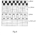
- the Figure 5 shows the current course curves through the switches S1, S2, S3, S4 and S5 of the circuit topology described with a clocked switch S5.
- the semiconductor switches S1, S2, S3, S4 change the polarity of the voltage applied to the motor 50, which in the Figure 6 corresponds to the envelope of u_Motor.
- the clocking of switch S5 then creates a square-wave voltage.
- the motor current i_ motor and the EMF u_ i_ motor are in phase with one another, as a result of which energy is transferred to the motor 50, whereby the in the Figure 6 illustrated speed n_ mech_ rpm increases in the acceleration phase.
Description
Die Erfindung betrifft eine Schaltungstopologie für einen Frequenzumrichter zum Betreiben einer elektrischen Maschine an einem elektrischen Wechselspannnungsnetz. Die Erfindung betrifft auch ein Verfahren zum Betreiben eines Motors an dem Frequenzumrichter.The invention relates to a circuit topology for a frequency converter for operating an electrical machine on an electrical AC voltage network. The invention also relates to a method for operating a motor on the frequency converter.
Bekannte Frequenzumrichter weisen eine Einspeiseeinheit auf, die über einen Gleichspannungs-Zwischenkreis mit einem Wechselrichter gekoppelt ist. In dem Gleichspannungs-Zwischenkreis ist in der Regel ein Zwischenkreiskondensator bereitgestellt.Known frequency converters have a feed unit which is coupled to an inverter via a DC voltage intermediate circuit. An intermediate circuit capacitor is generally provided in the DC voltage intermediate circuit.
Aus der
Weitere Frequenzumrichter sind beispielsweise in den Druckschriften
Die vorliegende Erfindung beschäftigt sich vornehmlich mit einem Frequenzumrichter in einer Topologie zum Ansteuern eines Elektromotors und insbesondere eines EC-Motors. Handelt es sich bei der elektrischen Maschine demnach um einen Elektromotor oder eine universell betreibbare Maschine im Motorbetrieb, so wirkt die Einspeiseeinheit als Gleichrichter, mittels welchem elektrische Energie aus dem Wechselspannungsnetz in den Zwischenkreis eingespeist wird.The present invention is primarily concerned with a frequency converter in a topology for controlling an electric motor and in particular an EC motor. If the electrical machine is accordingly an electric motor or a universally operable machine in motor mode, the feed unit acts as a rectifier, by means of which electrical energy is fed from the AC voltage network into the intermediate circuit.
Es ist dabei mittels des Frequenzumrichters möglich, eine Umwandlung zwischen einer Netz-Wechselspannung mit vorgegebener Netzfrequenz und einer für den Betrieb der elektrischen Maschine benötigten Wechselspannung mit bestimmter Frequenz durchzuführen. Hierzu erfolgt eine 2-stufige Spannungswandlung. In der ersten Stufe bewirkt die netzseitige Einspeiseeinheit des Frequenzumrichters eine Umwandlung zwischen der Netz-Wechselspannung und einer Gleichspannung des Gleichspannungs-Zwischenkreises. Dieser wiederum verbindet die Einspeiseeinheit mit einem Wechselrichter.It is possible by means of the frequency converter to carry out a conversion between an alternating mains voltage with a predetermined mains frequency and an alternating voltage with a certain frequency required for operating the electrical machine. For this purpose, a 2-stage voltage conversion takes place. In the first stage, the line-side infeed unit of the frequency converter converts between the AC line voltage and a DC voltage of the DC voltage intermediate circuit. This in turn connects the feed unit with an inverter.
Der Wechselrichter hat die Aufgabe die Zwischenkreis-Gleichspannung in eine geeignete Wechselspannung für den Motor umzuwandeln.The inverter has the task of converting the DC link voltage into a suitable AC voltage for the motor.
In dem Gleichspannungs-Zwischenkreis sorgt ein sogenannter Zwischenkreiskondensator mit einer ausreichend großen Kapazität dafür, dass eine erzeugte Welligkeit der Zwischenkreis-Gleichspannung für die nachfolgende Spannungswandlung mit dem Wechselrichter geglättet wird. Bevorzugt ist die Zwischenkreiskondensator-Kapazität auch groß genug, um bei einem kurzzeitigen Ausfall der versorgungsseitigen Netzwechselspannung einen unterbrechungsfreien Betrieb der elektrischen Maschine zu ermöglichen.In the DC voltage intermediate circuit, a so-called intermediate circuit capacitor with a sufficiently large capacitance ensures that a ripple generated in the intermediate circuit DC voltage is also used for the subsequent voltage conversion the inverter is smoothed. The intermediate circuit capacitor capacity is preferably also large enough to enable uninterrupted operation of the electrical machine in the event of a brief failure of the supply-side AC line voltage.
Nach dem Verbinden der Einspeiseeinheit mit den Phasen des Wechselspannungsnetzes erzeugt die Gleichrichtung die Gleichspannung in dem Zwischenkreis, wodurch der Zwischenkreiskondensator aufgeladen wird. Nachdem der Zwischenkreiskondensator so weit aufgeladen ist, dass die Zwischenkreis-Gleichspannung den erforderlichen Spannungswert erreicht hat, kann der Motor daran betrieben werden. Der Wechselrichter erzeugt eine Wechselspannung, so dass in den Strängen des Motors ein Drehstrom fließt. Als Wechselrichter ist hierzu z. B. eine H-Brücke oder Vollbrücke bekannt, die insofern nicht näher erläutert wird.After the supply unit has been connected to the phases of the AC voltage network, the rectification generates the DC voltage in the intermediate circuit, as a result of which the intermediate circuit capacitor is charged. After the intermediate circuit capacitor has been charged to such an extent that the intermediate circuit DC voltage has reached the required voltage value, the motor can be operated on it. The inverter generates an alternating voltage so that a three-phase current flows in the strands of the motor. As an inverter this is z. B. an H-bridge or full bridge is known, which is not explained in detail.
Bei der Anwendung eines EC-Motors an Wechselspannungsnetzten werden heutzutage typischerweise Zwischenkreiskondensatoren verwendet, überwelche ein getakteter mehrphasiger Wechselrichter dem EC-Motor die für den gewünschten Betriebspunkt passenden Ströme/Spannungen bzw. Energie zur Verfügung stellt.When an EC motor is used in AC voltage networks, intermediate circuit capacitors are typically used nowadays, over which a clocked multiphase inverter provides the EC motor with the currents / voltages or energy appropriate for the desired operating point.
Sinkt die Zwischenkreisspannung bei den bekannten Frequenzumrichtern unter die vom Elektromotor erzeugte induzierte Spannung ab, so kommt es durch die Dioden des Wechselrichters automatisch zu einer Rückspeisung von Energie vom Motor zur Elektronik und es wird ein negatives Drehmoment erzeugt, wodurch sich die Drehzahl des Motors verringert bzw. der Motor abgebremst wird.If the intermediate circuit voltage in the known frequency converters falls below the induced voltage generated by the electric motor, the diodes of the inverter automatically feed back energy from the motor to the electronics and a negative torque is generated, which reduces or reduces the speed of the motor . the motor is braked.
Ein entsprechend großer Elektrolytkondensator hilft dabei die Spannungseinbrüche gering zu halten, verursacht aber gleichzeitig je nach Auslegung eine Reduktion des Leistungsfaktors des Frequenzumrichters durch eine verzerrte Stromaufnahme des Gleichrichters vom Netz.A correspondingly large electrolytic capacitor helps to keep the voltage drops low, but at the same time, depending on the design, causes a reduction in the power factor of the frequency converter through a distorted current consumption of the rectifier from the mains.
Wird der Elektrolytkondensator in seiner Kapazität jedoch stark reduziert (schlanker Zwischenkreis), so erfolgt ein zu schnelles Absinken der Zwischenkreisspannung im Netznulldurchgang bzw. bei kurzen Netzunterbrechungen was ebenfalls zur Rückspeisung und auch zur Geräuschbildung im Motor führt.However, if the capacitance of the electrolytic capacitor is greatly reduced (slim intermediate circuit), the intermediate circuit voltage drops too quickly at zero crossing or in the event of short network interruptions, which also leads to feedback and noise in the motor.
Neben der Problematik des Rückspeisens von elektrischer Spannung des Motors in den Zwischenkreis ist der Zeitpunkt der Leistungsaufnahme innerhalb einer Netzperiode bei den bekannten Schaltungstopologien nicht frei wählbar. Ferner treten durch das Takten mit hoher Taktfrequenz im Wechselrichter nachteilige und demnach unerwünschte Halbleiterverluste auf.In addition to the problem of feeding electrical voltage from the motor back into the intermediate circuit, the time of power consumption within a network period cannot be freely selected with the known circuit topologies. Furthermore, due to the high clock frequency in the inverter, disadvantageous and therefore undesirable semiconductor losses occur.
Es ist daher Aufgabe der vorliegenden Erfindung, vorbesagte Nachteile zu überwinden und einen Frequenzumrichter bereit zu stellen, bei dem das Rückspeisen ins Netz unterbunden werden kann, dessen Leistungsaufnahme verbessert gesteuert werden kann und beim dem Halbleiterverluste im Wechselrichter reduziert werden können.It is therefore the object of the present invention to overcome the aforementioned disadvantages and to provide a frequency converter in which the feed back into the network can be prevented, the power consumption of which can be better controlled and in which semiconductor losses in the inverter can be reduced.
Diese Aufgabe wird durch die Merkmalskombination gemäß Anspruch 1 gelöst.This object is achieved by the combination of features according to
Ein Grundgedanke der vorliegenden Erfindung besteht in einer 5-Schalter Topologie, bei dem vier Schalter als Vierquadrantensteller angeordnet sind und ein zusätzlicher Schalter in den Leitungspfad in dem wechselrichterseitigen Teil des Gleichspannungs-Zwischenkreises angeordnet bzw. verschaltet ist.A basic idea of the present invention consists in a 5-switch topology in which four switches are arranged as four-quadrant controllers and an additional switch is arranged or connected in the conduction path in the inverter-side part of the DC voltage intermediate circuit.
Dabei wird der zusätzliche Schalter mit einer bestimmten hochfrequenten PWM-Frequenz getaktet. Die Schalter im Vierquadrantensteller werden nur niederfrequent getaktet, um die Motorströme zu kommutieren. Ist zusätzliche Schalter geschlossen wird ein Stromfluss über den Zwischenkreis ermöglicht und der Motor wird mit Energie gespeist. Wird der zusätzliche Schalter jedoch geöffnet, so wird der Motor in den Freilauf gesetzt.The additional switch is clocked with a certain high-frequency PWM frequency. The switches in the four-quadrant controller are only clocked at low frequencies in order to commutate the motor currents. If additional switches are closed, a current flow via the intermediate circuit is enabled and the motor is supplied with energy. However, if the additional switch is opened, the motor is set to freewheel.
Erfindungsgemäß wird demnach ein Frequenzumrichter zum Betreiben einer elektrischen Maschine an einem elektrischen Wechselspannungsnetz vorgeschlagen, wobei der Frequenzumrichter eine gleichrichtende Einspeiseeinheit und einen Wechselrichter aufweist, die miteinander über einen Gleichspannungs-Zwischenkreis verschaltet sind. Im Gleichspannungs-Zwischenkreis ist ein Zwischenkreiskondensator vorgesehen. Der Wechselrichter ist als Vierquadrantensteller mit vier Schaltern realisiert, wobei in einem Leitungspfad in dem wechselrichterseitigen Teil des Gleichspannungs-Zwischenkreises, welcher den Gleichspannungs-Zwischenkreis mit dem Wechselrichter verbindet, ein taktbarer Schalter angeordnet ist, welcher zum wahlweisen Öffnen oder Schließen des Leitungspfades oder für den getakteten Betrieb ausgelegt ist.According to the invention, a frequency converter for operating an electrical machine on an electrical AC voltage network is proposed, the frequency converter having a rectifying feed unit and an inverter which are connected to one another via a DC voltage intermediate circuit. An intermediate circuit capacitor is provided in the DC voltage intermediate circuit. The inverter is implemented as a four-quadrant controller with four switches, with a line path in the inverter-side part of the DC voltage intermediate circuit that connects the DC voltage intermediate circuit with the Inverter connects, a clockable switch is arranged, which is designed to selectively open or close the line path or for clocked operation.
Der zusätzliche Schalter bzw. die entsprechende Schalteinrichtung zwischen dem Gleichspannungs-Zwischenkreises und dem Wechselrichter kann als Halbleiterschalter mit parallel geschalteter Freilauf-Diode, wie z. B. als MOSFET oder aus zwei in Reihe bzw. Serie geschalteten Halbleiterschaltern mit je einer parallel geschalteten Freilauf-Diode realisiert werden, wobei die Durchlassrichtung der Freilauf-Dioden dann entgegengesetzt ist.The additional switch or the corresponding switching device between the DC voltage intermediate circuit and the inverter can be used as a semiconductor switch with a parallel-connected freewheeling diode, such as. B. be implemented as a MOSFET or from two series or series-connected semiconductor switches, each with a parallel-connected free-wheeling diode, the forward direction of the free-wheeling diodes then being opposite.
Weiter kann mit Vorteil vorgesehen sein, dass in der Schalteinrichtung bzw. dem entsprechenden Leitungspfad zur Realisierung des zusätzlichen Schalters eine Diode in einer Durchlassrichtung vorgesehen ist, die dazu ausgelegt ist, einen Stromfluss von dem wechselrichterseitigen Teil des Gleichspannungs-Zwischenkreises zu der Einspeiseeinheit zu verhindern.Furthermore, it can advantageously be provided that a diode is provided in a forward direction in the switching device or the corresponding line path for realizing the additional switch, which diode is designed to prevent a current flow from the inverter-side part of the DC voltage intermediate circuit to the feed unit.
Ein weiterer Aspekt der vorliegenden Erfindung betrifft ein Verfahren zum Betreiben eines wie zuvor beschriebenen Frequenzumrichters bei dem der besagte zusätzliche Schalter mittels einer PWM-Taktung getaktet wird.A further aspect of the present invention relates to a method for operating a frequency converter as described above in which the said additional switch is clocked by means of PWM clocking.
Bevorzugt ist es, wenn beim Betrieb der elektrischen Maschine die Schalter des Vierquadrantenstellers in einem niederfrequenten Takt getaktet werden, während der zusätzliche Schalter im Leitungspfad in dem wechselrichterseitigen Teil des Gleichspannungs-Zwischenkreises in einem hochfrequenten Takt getaktet wird, der vorzugsweise um ein Mehrfaches höher ist als der niederfrequente Takt.It is preferred if the switches of the four-quadrant controller are clocked in a low-frequency cycle during operation of the electrical machine, while the additional switch in the line path in the inverter-side part of the DC voltage intermediate circuit is clocked in a high-frequency cycle that is preferably several times higher than the low frequency clock.
Mit Vorteil erfolgt der Betrieb so, dass beim Öffnen des Schalters der Motor in den Freilauf gesetzt wird, während beim Schließen des Schalters der Stromfluss über den Gleichspannungs-Zwischenkreis zum Motor ermöglicht wird, wobei zwei der Schalter des Vierqaudrantenstellers für den Wechsel zwischen Freilauf und Motorspeisung nicht umgeschaltet werden müssen, während mittels der Schalterstellung der beiden anderen Schalter ein Strom über die beiden erstgenannten Schalter des Vierqaudrantenstellers gesteuert wird, wodurch die Verluste innerhalb des Wechselrichters auf die jeweiligen Schalter verteilt werden.The operation is advantageously carried out in such a way that when the switch is opened, the motor is set to freewheel, while when the switch is closed, the flow of current via the DC voltage intermediate circuit to the motor is enabled, with two of the switches in the quadrant controller for changing between freewheeling and motor supply do not have to be switched, while by means of the switch position of the other two switches, a current through the first two switches of the Vierqaudrantenstellers is controlled, whereby the losses within the inverter are distributed to the respective switch.
Mit Vorteil ist das Verfahren so ausgelegt, dass die Kommutierung der Schalter des Vierqaudrantenstellers nur erfolgt, um die am Motor angelegte Spannung im Vorzeichen zu kommutieren.The method is advantageously designed in such a way that the commutation of the switches of the four-quadrant controller only takes place in order to commutate the sign of the voltage applied to the motor.
In einer weiteren vorteilhaften Ausgestaltung der Erfindung ist vorgesehen, dass der Schalter im Leitungspfad in dem wechselrichterseitigen Teil des Gleichspannungs-Zwischenkreises zum Wechselrichter geöffnet wird, sobald die Zwischenkreis-Gleichspannung unterhalb der von der elektrischen Maschine erzeugten Klemmenspannung absinkt, womit ein Rückspeisen von induzierter Energie von der elektrischen Maschine in den Gleichspannungs-Zwischenkreis gezielt verhindert wird.In a further advantageous embodiment of the invention it is provided that the switch in the line path in the inverter-side part of the DC voltage intermediate circuit to the inverter is opened as soon as the intermediate circuit DC voltage falls below the terminal voltage generated by the electrical machine, which means that induced energy is fed back from the electrical machine in the DC voltage intermediate circuit is specifically prevented.
Andere vorteilhafte Weiterbildungen der Erfindung sind in den Unteransprüchen gekennzeichnet bzw. werden nachstehend zusammen mit der Beschreibung der bevorzugten Ausführung der Erfindung anhand der Figuren näher dargestellt.Other advantageous developments of the invention are characterized in the subclaims or are shown in more detail below together with the description of the preferred embodiment of the invention with reference to the figures.
Es zeigen:
- Fig. 1
- eine Schaltungstopologie eines erfindungsgemäßen Frequenzumrichters;
- Fig. 2
- die Schaltungsanordnung nach
Figur 1 - Fig. 3
- die Schaltungsanordnung nach
Figur 1 - Fig. 4
- drei beispielhafte Schaltungsanordnungen zur Realisierung des Schalters im Leitungspfad in dem wechselrichterseitigen Teil des Gleichspannungs-Zwischenkreises;
- Fig. 5
- Stromverlaufskurven durch die Schalter der Schaltungstopologie aus
Figur 1 - Fig. 6
- Motorkennwerte des an die Schaltungstopologie der
Figur 1
- Fig. 1
- a circuit topology of a frequency converter according to the invention;
- Fig. 2
- the circuit arrangement according to
Figure 1 with the switch closed in the conduction path in the inverter-side part of the DC voltage intermediate circuit; - Fig. 3
- the circuit arrangement according to
Figure 1 with the switch open in the conduction path in the inverter-side part of the DC voltage intermediate circuit; - Fig. 4
- three exemplary circuit arrangements for realizing the switch in the conduction path in the inverter-side part of the DC voltage intermediate circuit;
- Fig. 5
- Current curves through the switches of the circuit topology
Figure 1 and - Fig. 6
- Motor characteristics of the to the circuit topology of the
Figure 1 connected motor.
Im Folgenden wird die Erfindung mit Bezug auf die
In den
Der Frequenzumrichter 1 ist ausgebildet zum Betreiben einer elektrischen Maschine 50, die im vorliegenden Ausführungsbeispiel ein Elektromotor 50 ist. Der Frequenzumrichter 1 ist an einem elektrischen Wechselspannungsnetz 10 angeschlossen, wobei der Frequenzumrichter 1 eine gleichrichtende Einspeiseeinheit 20, nämlich einen Gleichrichter aus vier Dioden DG1, DG2 DG3, DG4 und einen Wechselrichter 40 aufweist, die miteinander über einen Gleichspannungs-Zwischenkreis 30 verbunden sind.The
Der Gleichspannungs-Zwischenkreis 30 verfügt über einen Zwischenkreiskondensator 31. Der Wechselrichter 40 ist als Vierquadrantensteller mit vier Leistungsschalter S1, S2, S3, S4 (wie z. B. MOSFET's) realisiert, wobei zu erkennen ist, dass in dem Leitungspfad 32 in dem wechselrichterseitigen Teil des Gleichspannungs-Zwischenkreises 30, welcher den Gleichspannungs-Zwischenkreis 30 mit dem Wechselrichter 40 verbindet, ein taktbarer Schalter S5 angeordnet ist, welcher zum wahlweisen Öffnen oder Schließen des Leitungspfades 32 oder für den getakteten Betrieb ausgelegt ist.The DC voltage
Der Schalter S5 bzw. die entsprechende Schalteinrichtung zwischen dem Gleichspannungs-Zwischenkreises 30 und dem Wechselrichter 40, kann wie in der
Die folgenden Betrachtungen beziehen sich beispielhaft auf einen positiven Stromfluss durch den Motor von Klemme 51 nach Klemme 52, wobei der Motor als Antrieb betrieben wird.The following considerations relate, for example, to a positive current flow through the motor from terminal 51 to
In der
In der
Die Schalter S1 und S4 müssen für den Wechsel zwischen der Speisung (wie in Figur 2) und dem Freilauf (wie in
Die
In der
Durch die Halbleiterschalter S1, S2, S3, S4 wird die Polarität der am Motor 50 angelegten Spannung verändert, was in der
Claims (7)
- Frequency converter (1) for operating an electrical machine (50) on an electrical AC voltage network (10), wherein the frequency converter (1) has a rectifier feed unit (20) and an inverter (40), which are connected to one another via a DC voltage intermediate circuit (30) with an intermediate circuit capacitor (31), wherein the inverter (40) is implemented as a four-quadrant actuator with four switches (S1, S2, S3, S4) in a H-bridge and a clockable switch (S5) which is arranged in a conduction path (32) in the inverter-side part of the DC voltage intermediate circuit (30) which connects the DC voltage intermediate circuit (30) to the inverter (40), and the clockable switch (S5) is formed, for selectively opening or closing the conduction path (32) or for clocked operation, characterized in that the switch (S5) is formed as a clocked switch comprising two series-connected semiconductor switches (S51, S52) each having a parallel-connected freewheeling diode (D1, D2), wherein the forward direction of the freewheeling diodes (D1, D2) is opposite and wherein the switches (S1, S2, S3, S4) are clocked in a low-frequency clock, while the switch (S5) is clocked in a high-frequency clock which is preferably several times higher than the low-frequency clock, and wherein a diode (D1, D2) of the switch (S5) is configured to prevent a current flow from the inverter-side part of the DC voltage intermediate circuit (30) to the feed unit (20).
- Frequency converter (1) according to claim 1, wherein the inverter (40) is formed as a three-phase inverter.
- Method for operating a frequency converter (1) according to one of the preceding claims 1 or 2, wherein the switches (S1, S2, S3, S4) are clocked in a low-frequency clock, while the switch (S5) is clocked in a high-frequency PWM clock, which, when opening the switch (S5), sets the motor in freewheeling operation, whereas, when closing the switch (S5), the current flow via the DC voltage intermediate circuit (30) to the motor is enabled and a commutation of the inverter (40) only takes place in order to commutate the voltage applied to the motor in sign.
- Method for operating a frequency converter (1) according to the preceding claim 3, wherein the switch (S5) is clocked by means of a PWM.
- Method according to one of claims 3 or 4, wherein the switches (S1, S3) of the four-quadrant controller are not switched over for the changeover between freewheeling operation and motor supply.
- Method according to claim 5, wherein in the freewheeling operation with the switch (S5) open, the freewheeling operation path can be varied through switching over at least one of the semiconductors of the inverter (40) in order to distribute the losses in the semiconductors of the inverter (40).
- Method according to one of the claims 3 to 6, wherein the switch (S5) is opened as soon as the intermediate circuit DC voltage decreases below the terminal voltage generated by the electric machine (50), thereby preventing a feedback of induced energy from the electric machine (50) into the DC voltage intermediate circuit (30).
Applications Claiming Priority (1)
| Application Number | Priority Date | Filing Date | Title |
|---|---|---|---|
| DE102017102955.9A DE102017102955A1 (en) | 2017-02-14 | 2017-02-14 | Five switches topology |
Publications (2)
| Publication Number | Publication Date |
|---|---|
| EP3361618A1 EP3361618A1 (en) | 2018-08-15 |
| EP3361618B1 true EP3361618B1 (en) | 2020-08-19 |
Family
ID=60275122
Family Applications (1)
| Application Number | Title | Priority Date | Filing Date |
|---|---|---|---|
| EP18156597.9A Active EP3361618B1 (en) | 2017-02-14 | 2018-02-14 | Five switch topology |
Country Status (3)
| Country | Link |
|---|---|
| EP (1) | EP3361618B1 (en) |
| CN (1) | CN206650589U (en) |
| DE (1) | DE102017102955A1 (en) |
Family Cites Families (7)
| Publication number | Priority date | Publication date | Assignee | Title |
|---|---|---|---|---|
| DE19739553A1 (en) | 1997-09-09 | 1999-03-11 | Siemens Ag | Pre-charging circuit for a capacitor connected to the output of a line-guided converter |
| JP4140552B2 (en) * | 2004-04-28 | 2008-08-27 | トヨタ自動車株式会社 | Automotive power supply device and automobile equipped with the same |
| EP2136465B1 (en) * | 2008-06-18 | 2017-08-09 | SMA Solar Technology AG | Inverter realized by a bridge circuit comprising slow and fast clocked switches |
| CN101707442A (en) * | 2009-11-16 | 2010-05-12 | 浙江大学 | Transformer-free inverter |
| DE102009047616A1 (en) * | 2009-12-08 | 2011-06-09 | Robert Bosch Gmbh | Inverter arrangement for operating an electric motor |
| CN104079227B (en) * | 2014-07-16 | 2016-09-07 | 浙江大学 | A kind of have the electric system reducing common mode disturbances ability |
| EP3264591A4 (en) * | 2015-02-24 | 2018-11-21 | Mitsubishi Electric Corporation | Electric drive device, and electric power steering device |
-
2017
- 2017-02-14 DE DE102017102955.9A patent/DE102017102955A1/en not_active Withdrawn
- 2017-04-11 CN CN201720373570.4U patent/CN206650589U/en active Active
-
2018
- 2018-02-14 EP EP18156597.9A patent/EP3361618B1/en active Active
Non-Patent Citations (1)
| Title |
|---|
| None * |
Also Published As
| Publication number | Publication date |
|---|---|
| EP3361618A1 (en) | 2018-08-15 |
| DE102017102955A1 (en) | 2018-08-16 |
| CN206650589U (en) | 2017-11-17 |
Similar Documents
| Publication | Publication Date | Title |
|---|---|---|
| EP1771935A2 (en) | Frequency converter comprising an intermediate circuit without a capacitor | |
| WO2009027326A1 (en) | Method for driving an electrical converter and associated apparatus | |
| EP2680421A1 (en) | Frequency inverter with intermediate circuits and method for preloading same | |
| EP1538736A2 (en) | Drive system | |
| DE102010041077A1 (en) | System for charging an energy storage and method for operating the charging system | |
| EP2523332A1 (en) | Frequency inverter with precharge series resistor and method for operating same | |
| DE112018006822T5 (en) | POWER CONVERTER, MOTOR MODULE AND ELECTRIC POWER STEERING DEVICE | |
| EP2741934B1 (en) | Method and circuit for the multi-phase operation of an electric motor | |
| EP2792061B1 (en) | Selective control of an alternating current motor or direct current motor | |
| EP3361618B1 (en) | Five switch topology | |
| EP0045951B1 (en) | Process for operating an inverter with an intermediate dc link circuit supplying an electric synchronous motor | |
| DE102017115639A1 (en) | Reduction of ripple current during switching operations of a bridge circuit | |
| WO2013023914A1 (en) | Inverter arrangement | |
| EP2182626B1 (en) | Method for operating a frequency converter and frequency converter operating by the method | |
| DE102011079214A1 (en) | Converter circuit for drive system used in electric vehicle, has inverters which are connected serially in loading/unloading state, and parallelly in driving state | |
| EP2266196A2 (en) | Supply unit for electric drives, and method for controlling said supply unit | |
| EP0474060A2 (en) | Four quadrant AC converter | |
| DE202017100796U1 (en) | Five switches topology | |
| WO2012107128A2 (en) | Method for operating a control system of an electric machine and system for controlling an electric machine | |
| DE102007052233A1 (en) | Power supply device for drive i.e. electric drive, in e.g. injection molding machine, has power controller provided on peak load, where drive is electrically connected to controller, and another power controller connected with drive | |
| EP0111088B1 (en) | Currant rectifier | |
| EP2523323A1 (en) | Frequency inverter with common mode choke and method for operating same | |
| EP2273669B1 (en) | Inverter for a switched reluctance motor and mechatronic system | |
| EP4358391A1 (en) | Propulsion system | |
| DE1413998C (en) | Arrangement for controlling or regulating the current of a line-commutated polyphase inverter |
Legal Events
| Date | Code | Title | Description |
|---|---|---|---|
| PUAI | Public reference made under article 153(3) epc to a published international application that has entered the european phase |
Free format text: ORIGINAL CODE: 0009012 |
|
| STAA | Information on the status of an ep patent application or granted ep patent |
Free format text: STATUS: THE APPLICATION HAS BEEN PUBLISHED |
|
| AK | Designated contracting states |
Kind code of ref document: A1 Designated state(s): AL AT BE BG CH CY CZ DE DK EE ES FI FR GB GR HR HU IE IS IT LI LT LU LV MC MK MT NL NO PL PT RO RS SE SI SK SM TR |
|
| AX | Request for extension of the european patent |
Extension state: BA ME |
|
| STAA | Information on the status of an ep patent application or granted ep patent |
Free format text: STATUS: REQUEST FOR EXAMINATION WAS MADE |
|
| 17P | Request for examination filed |
Effective date: 20190213 |
|
| RBV | Designated contracting states (corrected) |
Designated state(s): AL AT BE BG CH CY CZ DE DK EE ES FI FR GB GR HR HU IE IS IT LI LT LU LV MC MK MT NL NO PL PT RO RS SE SI SK SM TR |
|
| STAA | Information on the status of an ep patent application or granted ep patent |
Free format text: STATUS: EXAMINATION IS IN PROGRESS |
|
| 17Q | First examination report despatched |
Effective date: 20190904 |
|
| GRAP | Despatch of communication of intention to grant a patent |
Free format text: ORIGINAL CODE: EPIDOSNIGR1 |
|
| STAA | Information on the status of an ep patent application or granted ep patent |
Free format text: STATUS: GRANT OF PATENT IS INTENDED |
|
| RIC1 | Information provided on ipc code assigned before grant |
Ipc: H02M 7/5387 20070101ALI20200430BHEP Ipc: H02P 3/22 20060101ALI20200430BHEP Ipc: H02M 5/458 20060101AFI20200430BHEP |
|
| INTG | Intention to grant announced |
Effective date: 20200520 |
|
| GRAS | Grant fee paid |
Free format text: ORIGINAL CODE: EPIDOSNIGR3 |
|
| GRAA | (expected) grant |
Free format text: ORIGINAL CODE: 0009210 |
|
| STAA | Information on the status of an ep patent application or granted ep patent |
Free format text: STATUS: THE PATENT HAS BEEN GRANTED |
|
| AK | Designated contracting states |
Kind code of ref document: B1 Designated state(s): AL AT BE BG CH CY CZ DE DK EE ES FI FR GB GR HR HU IE IS IT LI LT LU LV MC MK MT NL NO PL PT RO RS SE SI SK SM TR |
|
| REG | Reference to a national code |
Ref country code: CH Ref legal event code: EP |
|
| REG | Reference to a national code |
Ref country code: DE Ref legal event code: R096 Ref document number: 502018002198 Country of ref document: DE |
|
| REG | Reference to a national code |
Ref country code: AT Ref legal event code: REF Ref document number: 1305090 Country of ref document: AT Kind code of ref document: T Effective date: 20200915 |
|
| REG | Reference to a national code |
Ref country code: NL Ref legal event code: FP Ref country code: IE Ref legal event code: FG4D Free format text: LANGUAGE OF EP DOCUMENT: GERMAN |
|
| REG | Reference to a national code |
Ref country code: SE Ref legal event code: TRGR |
|
| REG | Reference to a national code |
Ref country code: LT Ref legal event code: MG4D |
|
| PG25 | Lapsed in a contracting state [announced via postgrant information from national office to epo] |
Ref country code: NO Free format text: LAPSE BECAUSE OF FAILURE TO SUBMIT A TRANSLATION OF THE DESCRIPTION OR TO PAY THE FEE WITHIN THE PRESCRIBED TIME-LIMIT Effective date: 20201119 Ref country code: BG Free format text: LAPSE BECAUSE OF FAILURE TO SUBMIT A TRANSLATION OF THE DESCRIPTION OR TO PAY THE FEE WITHIN THE PRESCRIBED TIME-LIMIT Effective date: 20201119 Ref country code: HR Free format text: LAPSE BECAUSE OF FAILURE TO SUBMIT A TRANSLATION OF THE DESCRIPTION OR TO PAY THE FEE WITHIN THE PRESCRIBED TIME-LIMIT Effective date: 20200819 Ref country code: FI Free format text: LAPSE BECAUSE OF FAILURE TO SUBMIT A TRANSLATION OF THE DESCRIPTION OR TO PAY THE FEE WITHIN THE PRESCRIBED TIME-LIMIT Effective date: 20200819 Ref country code: GR Free format text: LAPSE BECAUSE OF FAILURE TO SUBMIT A TRANSLATION OF THE DESCRIPTION OR TO PAY THE FEE WITHIN THE PRESCRIBED TIME-LIMIT Effective date: 20201120 Ref country code: LT Free format text: LAPSE BECAUSE OF FAILURE TO SUBMIT A TRANSLATION OF THE DESCRIPTION OR TO PAY THE FEE WITHIN THE PRESCRIBED TIME-LIMIT Effective date: 20200819 Ref country code: PT Free format text: LAPSE BECAUSE OF FAILURE TO SUBMIT A TRANSLATION OF THE DESCRIPTION OR TO PAY THE FEE WITHIN THE PRESCRIBED TIME-LIMIT Effective date: 20201221 |
|
| PG25 | Lapsed in a contracting state [announced via postgrant information from national office to epo] |
Ref country code: IS Free format text: LAPSE BECAUSE OF FAILURE TO SUBMIT A TRANSLATION OF THE DESCRIPTION OR TO PAY THE FEE WITHIN THE PRESCRIBED TIME-LIMIT Effective date: 20201219 Ref country code: LV Free format text: LAPSE BECAUSE OF FAILURE TO SUBMIT A TRANSLATION OF THE DESCRIPTION OR TO PAY THE FEE WITHIN THE PRESCRIBED TIME-LIMIT Effective date: 20200819 Ref country code: RS Free format text: LAPSE BECAUSE OF FAILURE TO SUBMIT A TRANSLATION OF THE DESCRIPTION OR TO PAY THE FEE WITHIN THE PRESCRIBED TIME-LIMIT Effective date: 20200819 Ref country code: PL Free format text: LAPSE BECAUSE OF FAILURE TO SUBMIT A TRANSLATION OF THE DESCRIPTION OR TO PAY THE FEE WITHIN THE PRESCRIBED TIME-LIMIT Effective date: 20200819 |
|
| PG25 | Lapsed in a contracting state [announced via postgrant information from national office to epo] |
Ref country code: SM Free format text: LAPSE BECAUSE OF FAILURE TO SUBMIT A TRANSLATION OF THE DESCRIPTION OR TO PAY THE FEE WITHIN THE PRESCRIBED TIME-LIMIT Effective date: 20200819 Ref country code: RO Free format text: LAPSE BECAUSE OF FAILURE TO SUBMIT A TRANSLATION OF THE DESCRIPTION OR TO PAY THE FEE WITHIN THE PRESCRIBED TIME-LIMIT Effective date: 20200819 Ref country code: DK Free format text: LAPSE BECAUSE OF FAILURE TO SUBMIT A TRANSLATION OF THE DESCRIPTION OR TO PAY THE FEE WITHIN THE PRESCRIBED TIME-LIMIT Effective date: 20200819 Ref country code: EE Free format text: LAPSE BECAUSE OF FAILURE TO SUBMIT A TRANSLATION OF THE DESCRIPTION OR TO PAY THE FEE WITHIN THE PRESCRIBED TIME-LIMIT Effective date: 20200819 |
|
| REG | Reference to a national code |
Ref country code: DE Ref legal event code: R097 Ref document number: 502018002198 Country of ref document: DE |
|
| PG25 | Lapsed in a contracting state [announced via postgrant information from national office to epo] |
Ref country code: ES Free format text: LAPSE BECAUSE OF FAILURE TO SUBMIT A TRANSLATION OF THE DESCRIPTION OR TO PAY THE FEE WITHIN THE PRESCRIBED TIME-LIMIT Effective date: 20200819 Ref country code: AL Free format text: LAPSE BECAUSE OF FAILURE TO SUBMIT A TRANSLATION OF THE DESCRIPTION OR TO PAY THE FEE WITHIN THE PRESCRIBED TIME-LIMIT Effective date: 20200819 |
|
| PLBE | No opposition filed within time limit |
Free format text: ORIGINAL CODE: 0009261 |
|
| STAA | Information on the status of an ep patent application or granted ep patent |
Free format text: STATUS: NO OPPOSITION FILED WITHIN TIME LIMIT |
|
| PG25 | Lapsed in a contracting state [announced via postgrant information from national office to epo] |
Ref country code: SK Free format text: LAPSE BECAUSE OF FAILURE TO SUBMIT A TRANSLATION OF THE DESCRIPTION OR TO PAY THE FEE WITHIN THE PRESCRIBED TIME-LIMIT Effective date: 20200819 |
|
| 26N | No opposition filed |
Effective date: 20210520 |
|
| PG25 | Lapsed in a contracting state [announced via postgrant information from national office to epo] |
Ref country code: SI Free format text: LAPSE BECAUSE OF FAILURE TO SUBMIT A TRANSLATION OF THE DESCRIPTION OR TO PAY THE FEE WITHIN THE PRESCRIBED TIME-LIMIT Effective date: 20200819 |
|
| PG25 | Lapsed in a contracting state [announced via postgrant information from national office to epo] |
Ref country code: MC Free format text: LAPSE BECAUSE OF FAILURE TO SUBMIT A TRANSLATION OF THE DESCRIPTION OR TO PAY THE FEE WITHIN THE PRESCRIBED TIME-LIMIT Effective date: 20200819 |
|
| REG | Reference to a national code |
Ref country code: BE Ref legal event code: MM Effective date: 20210228 |
|
| PG25 | Lapsed in a contracting state [announced via postgrant information from national office to epo] |
Ref country code: LU Free format text: LAPSE BECAUSE OF NON-PAYMENT OF DUE FEES Effective date: 20210214 Ref country code: LI Free format text: LAPSE BECAUSE OF NON-PAYMENT OF DUE FEES Effective date: 20210228 Ref country code: CH Free format text: LAPSE BECAUSE OF NON-PAYMENT OF DUE FEES Effective date: 20210228 |
|
| PG25 | Lapsed in a contracting state [announced via postgrant information from national office to epo] |
Ref country code: IE Free format text: LAPSE BECAUSE OF NON-PAYMENT OF DUE FEES Effective date: 20210214 |
|
| PG25 | Lapsed in a contracting state [announced via postgrant information from national office to epo] |
Ref country code: BE Free format text: LAPSE BECAUSE OF NON-PAYMENT OF DUE FEES Effective date: 20210228 |
|
| PGFP | Annual fee paid to national office [announced via postgrant information from national office to epo] |
Ref country code: NL Payment date: 20230220 Year of fee payment: 6 |
|
| PGFP | Annual fee paid to national office [announced via postgrant information from national office to epo] |
Ref country code: FR Payment date: 20230217 Year of fee payment: 6 Ref country code: CZ Payment date: 20230202 Year of fee payment: 6 Ref country code: AT Payment date: 20230215 Year of fee payment: 6 |
|
| PGFP | Annual fee paid to national office [announced via postgrant information from national office to epo] |
Ref country code: SE Payment date: 20230220 Year of fee payment: 6 Ref country code: IT Payment date: 20230228 Year of fee payment: 6 Ref country code: GB Payment date: 20230221 Year of fee payment: 6 Ref country code: DE Payment date: 20230216 Year of fee payment: 6 |
|
| P01 | Opt-out of the competence of the unified patent court (upc) registered |
Effective date: 20230522 |
|
| PG25 | Lapsed in a contracting state [announced via postgrant information from national office to epo] |
Ref country code: CY Free format text: LAPSE BECAUSE OF FAILURE TO SUBMIT A TRANSLATION OF THE DESCRIPTION OR TO PAY THE FEE WITHIN THE PRESCRIBED TIME-LIMIT Effective date: 20200819 |
|
| PG25 | Lapsed in a contracting state [announced via postgrant information from national office to epo] |
Ref country code: HU Free format text: LAPSE BECAUSE OF FAILURE TO SUBMIT A TRANSLATION OF THE DESCRIPTION OR TO PAY THE FEE WITHIN THE PRESCRIBED TIME-LIMIT; INVALID AB INITIO Effective date: 20180214 |
|
| PGFP | Annual fee paid to national office [announced via postgrant information from national office to epo] |
Ref country code: NL Payment date: 20240220 Year of fee payment: 7 |