EP3361538A1 - Fuel cell stack - Google Patents
Fuel cell stack Download PDFInfo
- Publication number
- EP3361538A1 EP3361538A1 EP15905792.6A EP15905792A EP3361538A1 EP 3361538 A1 EP3361538 A1 EP 3361538A1 EP 15905792 A EP15905792 A EP 15905792A EP 3361538 A1 EP3361538 A1 EP 3361538A1
- Authority
- EP
- European Patent Office
- Prior art keywords
- fuel cell
- separator
- cell stack
- welded portion
- protrusion
- Prior art date
- Legal status (The legal status is an assumption and is not a legal conclusion. Google has not performed a legal analysis and makes no representation as to the accuracy of the status listed.)
- Granted
Links
Images


Classifications
-
- H—ELECTRICITY
- H01—ELECTRIC ELEMENTS
- H01M—PROCESSES OR MEANS, e.g. BATTERIES, FOR THE DIRECT CONVERSION OF CHEMICAL ENERGY INTO ELECTRICAL ENERGY
- H01M8/00—Fuel cells; Manufacture thereof
- H01M8/02—Details
- H01M8/0297—Arrangements for joining electrodes, reservoir layers, heat exchange units or bipolar separators to each other
-
- B—PERFORMING OPERATIONS; TRANSPORTING
- B23—MACHINE TOOLS; METAL-WORKING NOT OTHERWISE PROVIDED FOR
- B23K—SOLDERING OR UNSOLDERING; WELDING; CLADDING OR PLATING BY SOLDERING OR WELDING; CUTTING BY APPLYING HEAT LOCALLY, e.g. FLAME CUTTING; WORKING BY LASER BEAM
- B23K31/00—Processes relevant to this subclass, specially adapted for particular articles or purposes, but not covered by any single one of main groups B23K1/00 - B23K28/00
- B23K31/02—Processes relevant to this subclass, specially adapted for particular articles or purposes, but not covered by any single one of main groups B23K1/00 - B23K28/00 relating to soldering or welding
-
- H—ELECTRICITY
- H01—ELECTRIC ELEMENTS
- H01M—PROCESSES OR MEANS, e.g. BATTERIES, FOR THE DIRECT CONVERSION OF CHEMICAL ENERGY INTO ELECTRICAL ENERGY
- H01M8/00—Fuel cells; Manufacture thereof
- H01M8/02—Details
-
- H—ELECTRICITY
- H01—ELECTRIC ELEMENTS
- H01M—PROCESSES OR MEANS, e.g. BATTERIES, FOR THE DIRECT CONVERSION OF CHEMICAL ENERGY INTO ELECTRICAL ENERGY
- H01M8/00—Fuel cells; Manufacture thereof
- H01M8/02—Details
- H01M8/0202—Collectors; Separators, e.g. bipolar separators; Interconnectors
- H01M8/0204—Non-porous and characterised by the material
- H01M8/0206—Metals or alloys
-
- H—ELECTRICITY
- H01—ELECTRIC ELEMENTS
- H01M—PROCESSES OR MEANS, e.g. BATTERIES, FOR THE DIRECT CONVERSION OF CHEMICAL ENERGY INTO ELECTRICAL ENERGY
- H01M8/00—Fuel cells; Manufacture thereof
- H01M8/02—Details
- H01M8/0202—Collectors; Separators, e.g. bipolar separators; Interconnectors
- H01M8/0247—Collectors; Separators, e.g. bipolar separators; Interconnectors characterised by the form
-
- H—ELECTRICITY
- H01—ELECTRIC ELEMENTS
- H01M—PROCESSES OR MEANS, e.g. BATTERIES, FOR THE DIRECT CONVERSION OF CHEMICAL ENERGY INTO ELECTRICAL ENERGY
- H01M8/00—Fuel cells; Manufacture thereof
- H01M8/02—Details
- H01M8/0202—Collectors; Separators, e.g. bipolar separators; Interconnectors
- H01M8/0258—Collectors; Separators, e.g. bipolar separators; Interconnectors characterised by the configuration of channels, e.g. by the flow field of the reactant or coolant
-
- H—ELECTRICITY
- H01—ELECTRIC ELEMENTS
- H01M—PROCESSES OR MEANS, e.g. BATTERIES, FOR THE DIRECT CONVERSION OF CHEMICAL ENERGY INTO ELECTRICAL ENERGY
- H01M8/00—Fuel cells; Manufacture thereof
- H01M8/10—Fuel cells with solid electrolytes
- H01M8/1004—Fuel cells with solid electrolytes characterised by membrane-electrode assemblies [MEA]
-
- H—ELECTRICITY
- H01—ELECTRIC ELEMENTS
- H01M—PROCESSES OR MEANS, e.g. BATTERIES, FOR THE DIRECT CONVERSION OF CHEMICAL ENERGY INTO ELECTRICAL ENERGY
- H01M8/00—Fuel cells; Manufacture thereof
- H01M8/24—Grouping of fuel cells, e.g. stacking of fuel cells
-
- H—ELECTRICITY
- H01—ELECTRIC ELEMENTS
- H01M—PROCESSES OR MEANS, e.g. BATTERIES, FOR THE DIRECT CONVERSION OF CHEMICAL ENERGY INTO ELECTRICAL ENERGY
- H01M8/00—Fuel cells; Manufacture thereof
- H01M8/24—Grouping of fuel cells, e.g. stacking of fuel cells
- H01M8/241—Grouping of fuel cells, e.g. stacking of fuel cells with solid or matrix-supported electrolytes
-
- B—PERFORMING OPERATIONS; TRANSPORTING
- B23—MACHINE TOOLS; METAL-WORKING NOT OTHERWISE PROVIDED FOR
- B23K—SOLDERING OR UNSOLDERING; WELDING; CLADDING OR PLATING BY SOLDERING OR WELDING; CUTTING BY APPLYING HEAT LOCALLY, e.g. FLAME CUTTING; WORKING BY LASER BEAM
- B23K2101/00—Articles made by soldering, welding or cutting
- B23K2101/36—Electric or electronic devices
-
- H—ELECTRICITY
- H01—ELECTRIC ELEMENTS
- H01M—PROCESSES OR MEANS, e.g. BATTERIES, FOR THE DIRECT CONVERSION OF CHEMICAL ENERGY INTO ELECTRICAL ENERGY
- H01M8/00—Fuel cells; Manufacture thereof
- H01M8/10—Fuel cells with solid electrolytes
- H01M2008/1095—Fuel cells with polymeric electrolytes
-
- H—ELECTRICITY
- H01—ELECTRIC ELEMENTS
- H01M—PROCESSES OR MEANS, e.g. BATTERIES, FOR THE DIRECT CONVERSION OF CHEMICAL ENERGY INTO ELECTRICAL ENERGY
- H01M8/00—Fuel cells; Manufacture thereof
- H01M8/02—Details
- H01M8/0202—Collectors; Separators, e.g. bipolar separators; Interconnectors
-
- H—ELECTRICITY
- H01—ELECTRIC ELEMENTS
- H01M—PROCESSES OR MEANS, e.g. BATTERIES, FOR THE DIRECT CONVERSION OF CHEMICAL ENERGY INTO ELECTRICAL ENERGY
- H01M8/00—Fuel cells; Manufacture thereof
- H01M8/24—Grouping of fuel cells, e.g. stacking of fuel cells
- H01M8/241—Grouping of fuel cells, e.g. stacking of fuel cells with solid or matrix-supported electrolytes
- H01M8/242—Grouping of fuel cells, e.g. stacking of fuel cells with solid or matrix-supported electrolytes comprising framed electrodes or intermediary frame-like gaskets
-
- Y—GENERAL TAGGING OF NEW TECHNOLOGICAL DEVELOPMENTS; GENERAL TAGGING OF CROSS-SECTIONAL TECHNOLOGIES SPANNING OVER SEVERAL SECTIONS OF THE IPC; TECHNICAL SUBJECTS COVERED BY FORMER USPC CROSS-REFERENCE ART COLLECTIONS [XRACs] AND DIGESTS
- Y02—TECHNOLOGIES OR APPLICATIONS FOR MITIGATION OR ADAPTATION AGAINST CLIMATE CHANGE
- Y02E—REDUCTION OF GREENHOUSE GAS [GHG] EMISSIONS, RELATED TO ENERGY GENERATION, TRANSMISSION OR DISTRIBUTION
- Y02E60/00—Enabling technologies; Technologies with a potential or indirect contribution to GHG emissions mitigation
- Y02E60/30—Hydrogen technology
- Y02E60/50—Fuel cells
Definitions
- the present invention relates to a fuel cell stack constituted by stacking fuel cells having a separator.
- JP2015-22802A discloses that, in fuel cells that are adjacent, an anode separator of one fuel cell is welded to a cathode separator of the other fuel cell to join both separators.
- the separator includes a plurality of fluid flow passages formed such that a bottom portion that abuts on a membrane electrode assembly, and a protrusion that protrudes from this bottom portion are repeatedly arranged. The adjacent two separators are joined such that the protrusions are welded to one another.
- Such joining of the separators is performed for preventing positional deviation or the like of the separators when a fuel cell stack is manufactured. Therefore, all the protrusions of the separators are not welded, and some protrusions among the plurality of existing protrusions will be selected as separator welding positions.
- a protrusion height of the protrusion at a welding position will be higher than a protrusion height of another protrusion caused by a thickness of a welding bead.
- a contact surface pressure that acts on the separator varies. Then, the separator cannot contact the membrane electrode assembly uniformly within a contact surface, thus increasing contact resistance inside the fuel cell stack. The high part in the separator will be strongly pressed to the membrane electrode assembly, thus having a concern that the membrane electrode assembly deteriorates.
- An object of the present invention is to provide a fuel cell stack configured to reduce variation of a contact surface pressure of a separator and a membrane electrode assembly.
- a fuel cell stack constituted by stacking fuel cells including a membrane electrode assembly constituted by sandwiching an electrolyte membrane with a pair of electrodes and a pair of separators that have flow passages through which gas to be supplied to the membrane electrode assembly flows, the pair of separators being arranged across the membrane electrode assembly, is provided.
- the fuel cell stack includes a welded portion where the separators adjacent to one another in a stacking direction of the fuel cell are welded.
- the separator in the stacking direction at the welded portion has a height lower than a height of the separator other than the welded portion.
- a fuel cell is constituted such that an anode electrode as a fuel electrode and a cathode electrode as an oxidant electrode sandwich an electrolyte membrane.
- the fuel cell generates electric power using anode gas containing hydrogen supplied to the anode electrode and cathode gas containing oxygen supplied to the cathode electrode.
- Electrode reaction that progresses in both electrodes: the anode electrode and the cathode electrode is as follows.
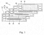
- FIG. 1 is an exploded view illustrating a schematic configuration of a fuel cell stack 100 according to a first embodiment.
- the fuel cell stack 100 illustrated in FIG. 1 is a fuel cell stack used for a vehicle such as an electric vehicle and a hybrid vehicle.
- the fuel cell stack 100 may be used as a power source of various electrical devices, not limited to the use in the automobile and the like.
- the fuel cell stack 100 is a stacked battery constituted such that a plurality of fuel cells 10 as unit cells are stacked.
- the fuel cell 10 that constitutes the fuel cell stack 100 includes a membrane electrode assembly (MEA) 20, an anode separator 30 arranged at one surface of the MEA 20, and a cathode separator 40 arranged at the other surface of the MEA 20.
- MEA membrane electrode assembly
- anode separator 30 arranged at one surface of the MEA
- a cathode separator 40 arranged at the other surface of the MEA 20.
- the MEA 20 is constituted of an electrolyte membrane 21, an anode electrode 22 arranged at one surface of the electrolyte membrane 21, and a cathode electrode 23 arranged at the other surface of the electrolyte membrane 21.
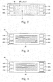
- FIG. 2 illustrates a front view of the MEA 20 that constitutes the fuel cell 10
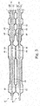
- FIG. 5 illustrates a partial vertical cross-sectional view of the fuel cell 10 at a position V-V in FIG. 2 .
- the electrolyte membrane 21 is a proton-conductive ion exchange membrane formed of fluorine-based resin.
- the anode electrode 22 is constituted such that, in an order from a side of the electrolyte membrane 21, an electrode catalyst layer made of an alloy such as platinum, a water-repellent layer made of fluorine resin or the like, and a gas diffusion layer made of a carbon cloth or the like are arranged.
- the cathode electrode 23, similarly to the anode electrode 22, is constituted such that, in an order from the electrolyte membrane 21 side, the electrode catalyst layer, the water-repellent layer, and the gas diffusion layer are arranged.
- a frame portion 50 made of resin is disposed along an assembly outer periphery.
- the frame portion 50 is a frame body made of a synthetic resin or the like, and integrally formed on the MEA 20.
- the frame portion 50 may be constituted as a plate-shaped material having rigidity, or may be constituted as a sheet-shaped member having flexibility.
- an anode gas supply manifold 51A At one end side (a left side in FIG. 2 ) of the frame portion 50, in an order from above, an anode gas supply manifold 51A, a cooling water supply manifold 52A, and a cathode gas supply manifold 53A are formed.
- an anode gas exhaust manifold 51B, a cooling water exhaust manifold 52B, and a cathode gas exhaust manifold 53B are formed.
- the anode separator 30 is a plate-shaped material formed of a conductive material such as metal.
- the anode separator 30 has an anode gas flow passage 34 that flows the anode gas on a surface at an MEA side, and has a cooling water flow passage 35 that flows cooling water on an opposite side surface of the MEA side.
- an anode gas supply manifold 31A At one end side (a left side in FIG. 3 ) of the anode separator 30, in an order from above, an anode gas supply manifold 31A, a cooling water supply manifold 32A, and a cathode gas supply manifold 33A are formed.
- an anode gas exhaust manifold 31B, a cooling water exhaust manifold 32B, and a cathode gas exhaust manifold 33B are formed.
- the anode gas supplied from the anode gas supply manifold 31A passes through the anode gas flow passage 34 to flow out to the anode gas exhaust manifold 31B.
- the cooling water supplied from the cooling water supply manifold 32A passes through the cooling water flow passage 35 to flow out to the cooling water exhaust manifold 32B.
- the cathode separator 40 is a plate-shaped material formed of a conductive material such as metal.
- the cathode separator 40 has a cathode gas flow passage 44 that flows the cathode gas on a surface at the MEA side, and has a cooling water flow passage 45 that flows the cooling water on an opposite side surface of the MEA side.
- an anode gas supply manifold 41A At one end side (a left side in FIG. 4 ) of the cathode separator 40, in an order from above, an anode gas supply manifold 41A, a cooling water supply manifold 42A, and a cathode gas supply manifold 43A are formed.
- an anode gas exhaust manifold 41B, a cooling water exhaust manifold 42B, and a cathode gas exhaust manifold 43B are formed.
- the cathode gas supplied from the cathode gas supply manifold 43A passes through the cathode gas flow passage 44 to flow out to the cathode gas exhaust manifold 43B.
- the cooling water supplied from the cooling water supply manifold 42A passes through the cooling water flow passage 45 to flow out to the cooling water exhaust manifold 42B.
- the anode gas supply manifolds 31A, 41A, and 51A are aligned in the stacking direction to function as one anode gas supply passage.
- the cooling water supply manifolds 32A, 42A, and 52A function as one cooling water supply passage
- the cathode gas supply manifolds 33A, 43A, and 53A function as one cathode gas supply passage.
- anode gas exhaust manifolds 31B, 41B, and 51B, the cooling water exhaust manifolds 32B, 42B, and 52B, and the cathode gas exhaust manifolds 33B, 43B, and 53B function as an anode gas exhaust passage, a cooling water exhaust passage, and a cathode gas exhaust passage respectively.
- the respective cooling water flow passages 35, 45 disposed on the anode separator 30 of one fuel cell 10 and the cathode separator 40 of the other fuel cell 10 are arranged to face one another.
- the cooling water flow passages 35, 45 thus arranged constitute one cooling passage.
- the fuel cell 10 is formed such that the anode separator 30 and the cathode separator 40 are bonded to the frame portion 50 with an adhesive 60.
- the anode separator 30 is arranged such that a surface at a side of the anode gas flow passage 34 is adjacent to one side surface of the MEA 20, and the cathode separator 40 is arranged such that a surface at a side of the cathode gas flow passage 44 is adjacent to the other side surface of the MEA 20.
- the adhesive 60 is arranged to surround separator outer edges and peripheral areas of the respective manifolds.
- the adhesive 60 has not only a function that bonds the respective members, but also a function as a sealing material that seals between the respective members. Accordingly, as the adhesive 60, an olefin-based adhesive, a silicon-based adhesive, or the like having an adhesion function and a seal function is employed. These adhesives are in a gel state before hardening, and in a solid state having elasticity after hardening.
- the anode separator 30 of one fuel cell 10 is joined to the cathode separator 40 of the other fuel cell 10 by welding.
- the two separators 30, 40 are thus welded and connected to form a separator assembly, thus mutually positioning both separators 30, 40.
- the separator assembly thus formed and the MEA 20 are alternately built up to stack them, thus constituting the fuel cell stack 100.
- the cathode separator 40 is constituted as an uneven-shaped member such that a flat-plate-shaped bottom portion 46 that abuts on the MEA 20, and a rectangular-shaped protrusion 47 that protrudes from the bottom portion 46 in the fuel cell stacking direction are sequentially arranged in a short side direction (a vertical direction in FIG. 4 ) within a separator surface.
- the cathode separator 40 has an uneven-shaped structure, thus including a plurality of cathode gas flow passages 44 on one side surface, and including a plurality of cooling water flow passages 45 on the other side surface.
- the anode separator 30 is also constituted as an uneven-shaped member such that a flat-plate-shaped bottom portion 36 that abuts on the MEA 20, and a rectangular-shaped protrusion 37 that protrudes from the bottom portion 36 in the fuel cell stacking direction are sequentially arranged in the separator short side direction (a vertical direction in FIG. 3 ).
- a plurality of anode gas flow passages 34 are formed on one side surface of the anode separator 30, and a plurality of cooling water flow passages 35 are formed on the other side surface of the anode separator 30.
- the above-described anode separator 30 and cathode separator 40 are welded to be mutually connected, in a state where the protrusion 37 and the protrusion 47 are positioned to be matched up.
- all the protrusions 37, 47 are not selected as welding positions, and several protrusions 37, 47 among the plurality of existing protrusions 37, 47 are selected as the welding positions.
- the protrusions 37, 47 in contact with both sides of the center bottom portions 36, 46 are the welding positions.
- the welding for forming the separator assembly is performed such that, in a state where the anode separator 30 and the cathode separator 40 are stuck, the protrusions 37, 47 are irradiated with laser from one separator side. This joins both separators 30, 40 via a welding bead 70 (a welded portion).
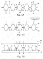
- the center bottom portions 36, 46 in contact with the two protrusions 37, 47 that are the welding positions are formed lower than the other bottom portions 36, 46 other than the center. That is, the cathode separator 40 is constituted such that an amount of protrusion h1 of the protrusion 47 on which the welding bead 70 is formed is lower than an amount of protrusion h2 of the protrusion 47 at other than the welding position.
- the anode separator 30 is similarly constituted such that an amount of protrusion of the protrusion 37 on which the welding bead 70 is formed is lower than an amount of protrusion of the protrusion 37 at other than the welding position.
- the protrusions 37, 47 at the welding position thus set low function as surface pressure adjustment portions that reduce variation of a surface pressure that acts on the separators 30, 40 in stacking of the fuel cell.
- the amounts of protrusion of the protrusions 37, 47 at the welding position are constituted lower than the amounts of protrusion of the other protrusions 37, 47.
- a protrusion height H1 of the protrusions 37, 47 at the welding position is lower than a protrusion height H2 of the other protrusions 37, 47.
- the protrusion height of the protrusions 37, 47 when constituting the fuel cell stack 100 means a distance from the MEA 20 to distal end surfaces of the protrusions 37, 47.
- the protrusion height H1 of the protrusions 37, 47 at the welding position is preferably set lower than the protrusion height H2 of the protrusions 37, 47 other than the welding position by a height (a thickness) of the welding bead 70.
- the welding bead 70 that joins the separators 30, 40 is, for example, as illustrated in FIG. 7 , formed along an extending direction of the gas flow passages 34, 44 (fluid flow passages) between the protrusions 37, 47.
- the welding bead 70 is constituted as a line-shaped bead (a line welded portion).
- the welding bead 70 may be constituted as a welding bead (a spot welded portion) formed in spots having a predetermined distance d in the extending direction of the gas flow passages 34, 44 (the fluid flow passages).
- a plurality of welding beads 70 are disposed in the gas-flow-passage extending direction.
- the predetermined distance d is set to a distance such that the protrusions 37, 47 between the welding beads 70 arranged in the gas-flow-passage extending direction do not bend in the stacking direction by the pressing force that acts on the separators 30, 40 when stacking the fuel cell.
- the predetermined distance d is preferably set to fulfill the following formula (1). [Expression 1] d ⁇ 384 ⁇ ⁇ E ⁇ I W 1 4
- At least a pair of protrusions 37, 47 of the anode separator 30 and the cathode separator 40 is the welding position, and the protrusion height (a separator height in the stacking direction) of the protrusions 37, 47 at the welding position is lower than the protrusion height of the protrusions 37, 47 other than the welding position.
- the protrusion height of the protrusions 37, 47 at the welding position is set lower than the protrusion height of the other protrusions 37, 47 by the height of the welding bead 70.
- Such a consideration of the height of the welding bead 70 ensures the reduction of the variation (variability) of the contact surface pressure of the separators 30, 40 and the MEA 20 in the fuel cell stack 100 with more certainty.
- the welding bead 70 that connects the anode separator 30 to the cathode separator 40 is constituted as the line-shaped bead formed along the extending direction of the gas flow passages 34, 44 between the protrusions 37, 47.
- Such a line shape of the welding bead 70 can join the anode separator 30 to the cathode separator 40 with more certainty.
- the welding bead 70 that connects the anode separator 30 to the cathode separator 40 may be constituted as a spot welding bead formed having the predetermined distance d in the extending direction of the gas flow passages 34, 44.
- the predetermined distance d is set to the distance such that the protrusions 37, 47 between the welding beads 70 do not bend in the stacking direction by the pressing force that acts on the separators 30, 40 when stacking of the fuel cell, thus ensuring reduction of deformation of the separators 30, 40 in stacking of the fuel cell.
- all the protrusions 37, 47 are set to have an identical amount of protrusion.
- these separators 30, 40 are connected by welding, as illustrated in FIG. 9A , a separator assembly having a gap by the height of the welding bead 70 between the protrusions 37, 47 other than the welding position is formed.
- the welding beads 70 are formed on the protrusions 47 different in an arranging direction of the gas flow passage 44.
- two protrusions 47 positioned next to the center protrusion 47 are set as the welding positions.
- at least one or more (one in this embodiment) protrusion 47 on which the welding is not performed in the arranging direction of the gas flow passage 44 will exist. It should be noted that the same applies to the anode separator 30.
- the bottom portions 36, 46 positioned inside the welding positions protrude in the stacking direction caused by the existence of the welding bead 70 to vary the contact surface pressure of the separators 30, 40 and the MEA 20.
- the protrusions 37, 47 at the welding position have deformed portions 37A, 47A elastically deformed by presswork.
- the deformed portions 37A, 47A are sidewall parts that connect the bottom portions 36, 46 to the end surfaces of the protrusions 37, 47. These deformed portions 37A, 47A function as the surface pressure adjustment portions.
- an advance compression forming (the presswork) is performed on the separator assembly. This advance compression forming will be described with reference to FIG. 9B .
- the advance compression forming is performed such that flat plate molds 80 are abutted on the end surface of the protrusion 37 of the anode separator 30 and the end surface of the protrusion 47 of the cathode separator 40 to compress these separators 30, 40 in the stacking direction.
- a compressive load that acts on the separators 30, 40 is set higher than a stacking load (the pressing force) that acts on the separators 30, 40 and the like in stacking of the fuel cell.
- the compressive load in the advance compression forming is determined considering a separator shape, a welding bead shape, and the like.
- the protrusion height H1 of the protrusions 37, 47 at the welding position is lower than the protrusion height H2 of the other protrusions 37, 47.
- all the bottom portions 36, 46 will be approximately aligned on the identical planar surface. Accordingly, when the fuel cell stack 100 is constituted using the separator assembly shaped by the advance compression forming, the reduction of the variation of the contact surface pressure of the separators 30, 40 and the MEA 20 is ensured.
- the protrusion height (the separator height in the stacking direction) of the protrusions 37, 47 at the welding position is lower than the protrusion height of the protrusions 37, 47 at other than the welding position.
- the sidewall parts of the protrusions 37, 47 at the welding positions of the separators 30, 40 are constituted as the deformed portions 37A, 47A configured to elastically deform. These deformed portions 37A, 47A are preliminarily deformed to set the protrusion height of the protrusions 37, 47 at the welding position lower than the protrusion height of the protrusions 37, 47 at other than the welded portion.
- the mold used in the advance compression forming has been described as the flat plate mold 80, but may be a mold other than the flat plate mold.
- the mold may be a mold shaped into an uneven shape corresponding to the separator shape to be configured to deform the deformed portions 37A, 47A of the protrusions 37, 47 in processing.
- a fuel cell stack 100 according to a modification of the first and second embodiments will be described with reference to FIG. 10 .
- the fuel cell stack 100 according to this modification is a fuel cell stack constituted using the separator assembly described in the first or second embodiment, and has a feature in an arrangement of the welding bead 70 that joins the separators 30, 40.
- the fuel cell stack 100 is constituted as a stacked body formed such that a plurality of fuel cells 10 are stacked.
- the welding beads 70 at a side of the anode separator 30 and the welding beads 70 at a side of the cathode separator 40 are formed shifted in the arranging direction of the gas flow passages 34, 44 as illustrated in FIG. 10 .
- the welding beads 70 of the anode separator 30 and the welding beads 70 of the cathode separator 40 may be shifted not only in the arranging direction of the gas flow passages 34, 44, but also in the extending direction of the gas flow passages 34, 44.
- the anode separator 30 and the cathode separator 40 are arranged across the MEA 20 of the fuel cell 10.
- the welding beads 70 at the anode separator 30 side and the welding beads 70 at the cathode separator 40 side are arranged shifted at least in one direction of the extending direction of the gas flow passages 34, 44 and the arranging direction of the gas flow passages 34, 44.
- Formation positions of the welding beads 70 are thus dispersed to ensure reduction of overlapping in the stacking direction of the welding beads 70 (the welding positions) in the stacked fuel cell 10.
- the variation of the contact surface pressure of the separators 30, 40 and the MEA 20 can be more effectively reduced.
- the fuel cell stack 100 illustrated in FIG. 10 when viewed from the stacking direction, all the welding beads 70 are not formed at an identical position, but several welding beads 70 are formed to overlap. Then, as illustrated in FIG. 11 , the fuel cell stack 100 may be constituted such that, when viewed from the stacking direction, all the welding beads 70 are formed at different positions.
- the advance compression forming is performed on all the surfaces of the anode separator 30 and the cathode separator 40 to elastically deform the deformed portions 37A, 47A of the protrusions 37, 47.
- the advance compression forming may be performed on only a region where the variation of the contact surface pressure is likely to become a problem in the anode separator 30 and the cathode separator 40.
- an anode gas pressure is high at a side of the anode gas exhaust manifold 31B, compared with a side of the anode gas supply manifold 31A.
- the contact pressure that acts on the anode separator 30 tends to increase at a position near the anode gas exhaust manifold 31B.
- the advance compression forming is performed on only the position near the anode gas exhaust manifold 31B, and the deformed portion 37A of the protrusion 37 in a region on which this compression forming is performed is elastically deformed.
- the variation of the contact surface pressure of the anode separator 30 and the MEA 20 can be reduced.
- the advance compression forming is preferably performed on a position near the cathode gas exhaust manifold 43B.
- the deformed portion 47A of the protrusion 47 in the region on which the advance compression forming is performed is elastically deformed to ensure the reduction of the variation of the contact surface pressure of the cathode separator 40 and the MEA 20.
- the anode separator 30 and the cathode separator 40 are constituted as flat-plate-shaped materials having grooves as the gas flow passages 34, 44.
- a surface that abuts on the cathode separator 40 of the anode separator 30 is formed as a flat surface.
- a surface that abuts on the anode separator 30 of the cathode separator 40 is formed as a flat surface.
- a depressed portion 48 (a welded portion) is formed. Inside the depressed portion 48, the welding bead 70 for joining the separators 30, 40 is disposed.
- the separator height H1 in the stacking direction at the welding position is lower than the separator height H2 other than the welding position.
- the flat surfaces of these separators 30, 40 can be abutted on one another.
- the variation of the contact surface pressure of the separators 30, 40 and the MEA 20 can be reduced to reduce the contact resistance inside the fuel cell stack 100.
- the bottom portions 36, 46 of the separators 30, 40 are not strongly pressed to the MEA 20 to ensure the reduction of the deterioration of the MEA 20.
- the depressed portion 48 is formed on the flat surface of the cathode separator 40.
- a depressed portion may be formed on the flat surface of the anode separator 30.
- Depressed portions may be formed on both flat surfaces of the separators 30, 40.
Landscapes
- Engineering & Computer Science (AREA)
- Life Sciences & Earth Sciences (AREA)
- Manufacturing & Machinery (AREA)
- Sustainable Development (AREA)
- Sustainable Energy (AREA)
- Chemical & Material Sciences (AREA)
- Chemical Kinetics & Catalysis (AREA)
- Electrochemistry (AREA)
- General Chemical & Material Sciences (AREA)
- Mechanical Engineering (AREA)
- Fuel Cell (AREA)
Abstract
Description
- The present invention relates to a fuel cell stack constituted by stacking fuel cells having a separator.
-
JP2015-22802A - Such joining of the separators is performed for preventing positional deviation or the like of the separators when a fuel cell stack is manufactured. Therefore, all the protrusions of the separators are not welded, and some protrusions among the plurality of existing protrusions will be selected as separator welding positions.
- When the separators are welded using only several protrusions, in stacking of a plurality of fuel cells, a protrusion height of the protrusion at a welding position will be higher than a protrusion height of another protrusion caused by a thickness of a welding bead. Thus, if a part of the fluid flow passage of the separator is higher than another part, in constituting of the fuel cell stack, a contact surface pressure that acts on the separator varies. Then, the separator cannot contact the membrane electrode assembly uniformly within a contact surface, thus increasing contact resistance inside the fuel cell stack. The high part in the separator will be strongly pressed to the membrane electrode assembly, thus having a concern that the membrane electrode assembly deteriorates.
- An object of the present invention is to provide a fuel cell stack configured to reduce variation of a contact surface pressure of a separator and a membrane electrode assembly.
- According to an aspect of this invention, a fuel cell stack constituted by stacking fuel cells including a membrane electrode assembly constituted by sandwiching an electrolyte membrane with a pair of electrodes and a pair of separators that have flow passages through which gas to be supplied to the membrane electrode assembly flows, the pair of separators being arranged across the membrane electrode assembly, is provided. The fuel cell stack includes a welded portion where the separators adjacent to one another in a stacking direction of the fuel cell are welded. The separator in the stacking direction at the welded portion has a height lower than a height of the separator other than the welded portion.
-
-
FIG. 1 is a schematic configuration diagram of a fuel cell stack according to a first embodiment of the present invention. -
FIG. 2 is a front view of a membrane electrode assembly that constitutes a fuel cell. -
FIG. 3 is a front view of an anode separator that constitutes the fuel cell. -
FIG. 4 is a front view of a cathode separator that constitutes the fuel cell. -
FIG. 5 is a partial vertical cross-sectional view of the fuel cell stack. -
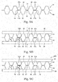
FIG. 6A is a view illustrating a separator assembly such that two separators are welded. -
FIG. 6B is a view illustrating the separator assembly in stacking of the fuel cell. -
FIG. 6C is a view illustrating a state of the separator assembly in constituting of the fuel cell stack. -
FIG. 7 is a view illustrating an exemplary welding bead formed in welding of the separator. -
FIG. 8 is a view illustrating an exemplary welding bead formed in welding of the separator. -
FIG. 9A is a view illustrating a separator assembly such that separators are welded according to a second embodiment of the present invention. -
FIG. 9B is a view illustrating a state of the separator assembly in advance compression forming. -
FIG. 9C is a view illustrating a state of the separator assembly in constituting of a fuel cell stack. -
FIG. 10 is a view illustrating a cross-sectional surface in a stacking direction of a fuel cell stack according to one modification of the first and second embodiments. -
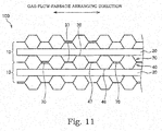
FIG. 11 is a view illustrating a cross-sectional surface in a stacking direction of a fuel cell stack according to another modification of the first and second embodiments. -
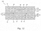
FIG. 12 is an explanatory view of another modification in a separator structure of a fuel cell stack. - The following describes embodiments of the present invention with reference to the drawings and the like.
- A fuel cell is constituted such that an anode electrode as a fuel electrode and a cathode electrode as an oxidant electrode sandwich an electrolyte membrane. The fuel cell generates electric power using anode gas containing hydrogen supplied to the anode electrode and cathode gas containing oxygen supplied to the cathode electrode. Electrode reaction that progresses in both electrodes: the anode electrode and the cathode electrode is as follows.
- Anode electrode:
2H2 → 4H+ + 4e- ··· (1)
Cathode electrode:
4H+ + 4e- + O2 → 2H2O ··· (2)
With these electrode reactions (1) and (2), the fuel cell generates an electromotive force with about 1 V (volt). -
FIG. 1 is an exploded view illustrating a schematic configuration of afuel cell stack 100 according to a first embodiment. - The
fuel cell stack 100 illustrated inFIG. 1 is a fuel cell stack used for a vehicle such as an electric vehicle and a hybrid vehicle. However, thefuel cell stack 100 may be used as a power source of various electrical devices, not limited to the use in the automobile and the like. - The
fuel cell stack 100 is a stacked battery constituted such that a plurality offuel cells 10 as unit cells are stacked. - The
fuel cell 10 that constitutes thefuel cell stack 100 includes a membrane electrode assembly (MEA) 20, ananode separator 30 arranged at one surface of theMEA 20, and acathode separator 40 arranged at the other surface of theMEA 20. Thus, in thefuel cell stack 100, a pair ofseparators MEA 20. - As illustrated in
FIG. 2 andFIG. 5 , theMEA 20 is constituted of anelectrolyte membrane 21, ananode electrode 22 arranged at one surface of theelectrolyte membrane 21, and acathode electrode 23 arranged at the other surface of theelectrolyte membrane 21. It should be noted thatFIG. 2 illustrates a front view of theMEA 20 that constitutes thefuel cell 10, andFIG. 5 illustrates a partial vertical cross-sectional view of thefuel cell 10 at a position V-V inFIG. 2 . - As illustrated in
FIG. 5 , theelectrolyte membrane 21 is a proton-conductive ion exchange membrane formed of fluorine-based resin. Theanode electrode 22 is constituted such that, in an order from a side of theelectrolyte membrane 21, an electrode catalyst layer made of an alloy such as platinum, a water-repellent layer made of fluorine resin or the like, and a gas diffusion layer made of a carbon cloth or the like are arranged. Thecathode electrode 23, similarly to theanode electrode 22, is constituted such that, in an order from theelectrolyte membrane 21 side, the electrode catalyst layer, the water-repellent layer, and the gas diffusion layer are arranged. - On the
MEA 20, aframe portion 50 made of resin is disposed along an assembly outer periphery. Theframe portion 50 is a frame body made of a synthetic resin or the like, and integrally formed on theMEA 20. Theframe portion 50 may be constituted as a plate-shaped material having rigidity, or may be constituted as a sheet-shaped member having flexibility. - As illustrated in
FIG. 2 , at one end side (a left side inFIG. 2 ) of theframe portion 50, in an order from above, an anodegas supply manifold 51A, a coolingwater supply manifold 52A, and a cathodegas supply manifold 53A are formed. At the other end side (a right side inFIG. 2 ) of theframe portion 50, in an order from above, an anodegas exhaust manifold 51B, a coolingwater exhaust manifold 52B, and a cathodegas exhaust manifold 53B are formed. - As illustrated in
FIG. 3 andFIG. 5 , theanode separator 30 is a plate-shaped material formed of a conductive material such as metal. Theanode separator 30 has an anodegas flow passage 34 that flows the anode gas on a surface at an MEA side, and has a coolingwater flow passage 35 that flows cooling water on an opposite side surface of the MEA side. - As illustrated in
FIG. 3 , at one end side (a left side inFIG. 3 ) of theanode separator 30, in an order from above, an anodegas supply manifold 31A, a coolingwater supply manifold 32A, and a cathodegas supply manifold 33A are formed. At the other end side (a right side inFIG. 3 ) of theanode separator 30, in an order from above, an anodegas exhaust manifold 31B, a coolingwater exhaust manifold 32B, and a cathodegas exhaust manifold 33B are formed. - The anode gas supplied from the anode
gas supply manifold 31A passes through the anodegas flow passage 34 to flow out to the anodegas exhaust manifold 31B. The cooling water supplied from the coolingwater supply manifold 32A passes through the coolingwater flow passage 35 to flow out to the coolingwater exhaust manifold 32B. - As illustrated in
FIG. 4 andFIG. 5 , thecathode separator 40 is a plate-shaped material formed of a conductive material such as metal. Thecathode separator 40 has a cathodegas flow passage 44 that flows the cathode gas on a surface at the MEA side, and has a coolingwater flow passage 45 that flows the cooling water on an opposite side surface of the MEA side. - As illustrated in
FIG. 4 , at one end side (a left side inFIG. 4 ) of thecathode separator 40, in an order from above, an anodegas supply manifold 41A, a coolingwater supply manifold 42A, and a cathodegas supply manifold 43A are formed. At the other end side (a right side inFIG. 4 ) of thecathode separator 40, in an order from above, an anodegas exhaust manifold 41B, a coolingwater exhaust manifold 42B, and a cathodegas exhaust manifold 43B are formed. - The cathode gas supplied from the cathode
gas supply manifold 43A passes through the cathodegas flow passage 44 to flow out to the cathodegas exhaust manifold 43B. The cooling water supplied from the coolingwater supply manifold 42A passes through the coolingwater flow passage 45 to flow out to the coolingwater exhaust manifold 42B. - When the
fuel cell stack 100 is constituted such that thefuel cell 10 having theMEA 20, theanode separator 30, and thecathode separator 40 is stacked, the anodegas supply manifolds water supply manifolds gas supply manifolds gas exhaust manifolds water exhaust manifolds gas exhaust manifolds - It should be noted that, as illustrated in
FIG. 5 , in adjacent twofuel cells 10, the respective coolingwater flow passages anode separator 30 of onefuel cell 10 and thecathode separator 40 of theother fuel cell 10 are arranged to face one another. The coolingwater flow passages - The
fuel cell 10 is formed such that theanode separator 30 and thecathode separator 40 are bonded to theframe portion 50 with an adhesive 60. In a state where theanode separator 30 and thecathode separator 40 are bonded to theframe portion 50, theanode separator 30 is arranged such that a surface at a side of the anodegas flow passage 34 is adjacent to one side surface of theMEA 20, and thecathode separator 40 is arranged such that a surface at a side of the cathodegas flow passage 44 is adjacent to the other side surface of theMEA 20. - In these
separators - The following describes the configurations of the
anode separator 30 and thecathode separator 40 in thefuel cell stack 100 according to this embodiment in more detail, with reference toFIG. 6A to FIG. 6C . - In the adjacent two
fuel cells 10, as illustrated inFIG. 6A , theanode separator 30 of onefuel cell 10 is joined to thecathode separator 40 of theother fuel cell 10 by welding. The twoseparators separators MEA 20 are alternately built up to stack them, thus constituting thefuel cell stack 100. - The
cathode separator 40 is constituted as an uneven-shaped member such that a flat-plate-shapedbottom portion 46 that abuts on theMEA 20, and a rectangular-shapedprotrusion 47 that protrudes from thebottom portion 46 in the fuel cell stacking direction are sequentially arranged in a short side direction (a vertical direction inFIG. 4 ) within a separator surface. Thecathode separator 40 has an uneven-shaped structure, thus including a plurality of cathodegas flow passages 44 on one side surface, and including a plurality of coolingwater flow passages 45 on the other side surface. - The
anode separator 30 is also constituted as an uneven-shaped member such that a flat-plate-shapedbottom portion 36 that abuts on theMEA 20, and a rectangular-shapedprotrusion 37 that protrudes from thebottom portion 36 in the fuel cell stacking direction are sequentially arranged in the separator short side direction (a vertical direction inFIG. 3 ). With such a configuration, a plurality of anodegas flow passages 34 are formed on one side surface of theanode separator 30, and a plurality of coolingwater flow passages 35 are formed on the other side surface of theanode separator 30. - The above-described
anode separator 30 andcathode separator 40 are welded to be mutually connected, in a state where theprotrusion 37 and theprotrusion 47 are positioned to be matched up. When the separator assembly is formed, all theprotrusions several protrusions protrusions protrusions center bottom portions - The welding for forming the separator assembly is performed such that, in a state where the
anode separator 30 and thecathode separator 40 are stuck, theprotrusions separators - It should be noted that, in the
anode separator 30 and thecathode separator 40, thecenter bottom portions protrusions bottom portions cathode separator 40 is constituted such that an amount of protrusion h1 of theprotrusion 47 on which thewelding bead 70 is formed is lower than an amount of protrusion h2 of theprotrusion 47 at other than the welding position. Theanode separator 30 is similarly constituted such that an amount of protrusion of theprotrusion 37 on which thewelding bead 70 is formed is lower than an amount of protrusion of theprotrusion 37 at other than the welding position. Theprotrusions separators - When stacking the fuel cell, to a stacked body formed such that the separator assembly and the
MEA 20 are alternately built up, a predetermined pressing force is added in the stacking direction. In the separator assembly illustrated inFIG. 6A , a gap exists between bothseparators welding bead 70. With the pressing force in stacking, theanode separator 30 and thecathode separator 40 will overlap one another such that theprotrusion 37 abuts on theprotrusion 47 as illustrated inFIG. 6B . - When the amounts of protrusion of all the
protrusions center bottom portions welding bead 70, as indicated by the dashed line inFIG. 6B . - However, in this embodiment, the amounts of protrusion of the
protrusions other protrusions fuel cell stack 100, a protrusion height H1 of theprotrusions other protrusions fuel cell stack 100, as illustrated inFIG. 6C , all thebottom portions protrusions fuel cell stack 100 means a distance from theMEA 20 to distal end surfaces of theprotrusions - In the
fuel cell stack 100, in order to align thebottom portions 36 of theanode separator 30 on the identical planar surface, and to align thebottom portions 46 of thecathode separator 40 on the identical planar surface, the protrusion height H1 of theprotrusions protrusions welding bead 70. - As described above, the
welding bead 70 that joins theseparators FIG. 7 , formed along an extending direction of thegas flow passages 34, 44 (fluid flow passages) between theprotrusions welding bead 70 is constituted as a line-shaped bead (a line welded portion). - It should be noted that, as illustrated in
FIG. 8 , thewelding bead 70 may be constituted as a welding bead (a spot welded portion) formed in spots having a predetermined distance d in the extending direction of thegas flow passages 34, 44 (the fluid flow passages). In this case, a plurality ofwelding beads 70 are disposed in the gas-flow-passage extending direction. - The predetermined distance d is set to a distance such that the
protrusions welding beads 70 arranged in the gas-flow-passage extending direction do not bend in the stacking direction by the pressing force that acts on theseparators
[Expression 1]
- δ : Allowable deformation amount determined according to membrane electrode assembly
- E : Young's modulus of material of separator
- I : Second moment of area determined by shapes of bottom portion and protrusion
- W : Surface pressure that acts on separator
- With the above-described
fuel cell stack 100 in the first embodiment, the following effect can be obtained. - In the
fuel cell stack 100, at least a pair ofprotrusions anode separator 30 and thecathode separator 40 is the welding position, and the protrusion height (a separator height in the stacking direction) of theprotrusions protrusions - With such configurations of the
separators FIG. 6C , when constituting thefuel cell stack 100, all thebottom portions 36 of theanode separator 30 will be approximately aligned on the identical planar surface, and all thebottom portions 46 of thecathode separator 40 will be approximately aligned on the identical planar surface. This can reduce the variation of the contact surface pressure of theseparators MEA 20 to ensure reduction of the contact resistance inside thefuel cell stack 100. Furthermore, thebottom portions separators MEA 20 to ensure reduction of deterioration of theMEA 20. - In the
anode separator 30 and thecathode separator 40, the protrusion height of theprotrusions other protrusions welding bead 70. Such a consideration of the height of thewelding bead 70 ensures the reduction of the variation (variability) of the contact surface pressure of theseparators MEA 20 in thefuel cell stack 100 with more certainty. - The
welding bead 70 that connects theanode separator 30 to thecathode separator 40 is constituted as the line-shaped bead formed along the extending direction of thegas flow passages protrusions welding bead 70 can join theanode separator 30 to thecathode separator 40 with more certainty. - It should be noted that the
welding bead 70 that connects theanode separator 30 to thecathode separator 40 may be constituted as a spot welding bead formed having the predetermined distance d in the extending direction of thegas flow passages anode separator 30 and thecathode separator 40 are joined at minimal welding positions, thus ensuring reduction of welding work hours. The predetermined distance d is set to the distance such that theprotrusions welding beads 70 do not bend in the stacking direction by the pressing force that acts on theseparators separators - The following describes a
fuel cell stack 100 according to a second embodiment of the present invention with reference toFIG. 9A to FIG. 9C . A technical idea of this embodiment can be combined with a technical idea of the first embodiment as necessary. The following embodiments use identical reference numerals to components that have functions identical to those of the first embodiment, and therefore such elements may not be further elaborated here. - In the second embodiment, in the
anode separator 30 and thecathode separator 40 before the constitution of thefuel cell stack 100, all theprotrusions separators FIG. 9A , a separator assembly having a gap by the height of thewelding bead 70 between theprotrusions - Observing the
cathode separator 40, thewelding beads 70 are formed on theprotrusions 47 different in an arranging direction of thegas flow passage 44. As illustrated inFIG. 9A , in this embodiment, twoprotrusions 47 positioned next to thecenter protrusion 47 are set as the welding positions. Thus, between theprotrusions protrusion 47 on which the welding is not performed in the arranging direction of thegas flow passage 44 will exist. It should be noted that the same applies to theanode separator 30. - When the fuel cell stacking is performed using directly thus constituted separator assembly, the
bottom portions welding bead 70 to vary the contact surface pressure of theseparators MEA 20. - Therefore, in the
anode separator 30 and thecathode separator 40 in this embodiment, theprotrusions portions deformed portions bottom portions protrusions deformed portions - In this embodiment, in a step before the stacking of the separator assembly and the
MEA 20, an advance compression forming (the presswork) is performed on the separator assembly. This advance compression forming will be described with reference toFIG. 9B . - As illustrated in
FIG. 9B , the advance compression forming is performed such thatflat plate molds 80 are abutted on the end surface of theprotrusion 37 of theanode separator 30 and the end surface of theprotrusion 47 of thecathode separator 40 to compress theseseparators separators separators - When the advance compression forming is thus performed, stress concentrates on the
deformed portions protrusions deformed portions deformed portions protrusion 37 of the anode separator abuts on theprotrusion 47 of thecathode separator 40 where thewelding bead 70 does not exist. As a result, in thecathode separator 40, the protrusion height H 1 of theprotrusion 47 on which thewelding bead 70 is formed becomes lower than the protrusion height H2 of theprotrusion 47 at other than the welding position. In theanode separator 30, similarly, the protrusion height of theprotrusion 37 on which thewelding bead 70 is formed becomes lower than the protrusion height of theprotrusion 37 at other than the welding position. - In the separator assembly thus shaped by the advance compression forming, in constituting of the
fuel cell stack 100, as illustrated inFIG. 9C , the protrusion height H1 of theprotrusions other protrusions bottom portions fuel cell stack 100 is constituted using the separator assembly shaped by the advance compression forming, the reduction of the variation of the contact surface pressure of theseparators MEA 20 is ensured. - With the above-described the
fuel cell stack 100 in the second embodiment, the following effect can be obtained. - In the
fuel cell stack 100, in theanode separator 30 and thecathode separator 40, the protrusion height (the separator height in the stacking direction) of theprotrusions protrusions protrusions separators deformed portions deformed portions protrusions protrusions - With such constitution of the
fuel cell stack 100 using theseparators FIG. 9C , in constituting of thefuel cell stack 100, all thebottom portions 36 of theanode separator 30 will be approximately aligned on the identical planar surface, and all thebottom portions 46 of thecathode separator 40 will be approximately aligned on the identical planar surface. This can reduce the variation of the contact surface pressure of theseparators MEA 20 to ensure reduction of the contact resistance inside thefuel cell stack 100. Furthermore, thebottom portions separators MEA 20 to ensure reduction of deterioration of theMEA 20. - In the
fuel cell stack 100, between theprotrusions protrusions more protrusions gas flow passages gas flow passages deformed portions deformed portions protrusions separators - The mold used in the advance compression forming has been described as the
flat plate mold 80, but may be a mold other than the flat plate mold. For example, the mold may be a mold shaped into an uneven shape corresponding to the separator shape to be configured to deform thedeformed portions protrusions - A
fuel cell stack 100 according to a modification of the first and second embodiments will be described with reference toFIG. 10 . - The
fuel cell stack 100 according to this modification is a fuel cell stack constituted using the separator assembly described in the first or second embodiment, and has a feature in an arrangement of thewelding bead 70 that joins theseparators - The
fuel cell stack 100 is constituted as a stacked body formed such that a plurality offuel cells 10 are stacked. In twoseparators MEA 20 of onecertain fuel cell 10, thewelding beads 70 at a side of theanode separator 30 and thewelding beads 70 at a side of thecathode separator 40 are formed shifted in the arranging direction of thegas flow passages FIG. 10 . - When the
welding beads 70 are formed in spots as illustrated inFIG. 8 , thewelding beads 70 of theanode separator 30 and thewelding beads 70 of thecathode separator 40 may be shifted not only in the arranging direction of thegas flow passages gas flow passages - With the above-described
fuel cell stack 100 according to the modification, the following effect can be obtained. - In the
fuel cell stack 100, theanode separator 30 and thecathode separator 40 are arranged across theMEA 20 of thefuel cell 10. In the twoseparators welding beads 70 at theanode separator 30 side and thewelding beads 70 at thecathode separator 40 side are arranged shifted at least in one direction of the extending direction of thegas flow passages gas flow passages - Formation positions of the
welding beads 70 are thus dispersed to ensure reduction of overlapping in the stacking direction of the welding beads 70 (the welding positions) in the stackedfuel cell 10. As a result, in constituting of thefuel cell stack 100, the variation of the contact surface pressure of theseparators MEA 20 can be more effectively reduced. - In the
fuel cell stack 100 illustrated inFIG. 10 , when viewed from the stacking direction, all thewelding beads 70 are not formed at an identical position, butseveral welding beads 70 are formed to overlap. Then, as illustrated inFIG. 11 , thefuel cell stack 100 may be constituted such that, when viewed from the stacking direction, all thewelding beads 70 are formed at different positions. - Thus, when viewed from the stacking direction, all the formation positions of the
welding beads 70 do not overlap to more ensure the reduction of the variation of the contact surface pressure of theseparators MEA 20. - The embodiment of the present invention described above is merely illustration of a part of application example of the present invention and not of the nature to limit the technical scope of the present invention to the specific constructions of the above embodiment.
- In the second embodiment, the advance compression forming is performed on all the surfaces of the
anode separator 30 and thecathode separator 40 to elastically deform thedeformed portions protrusions anode separator 30 and thecathode separator 40. - For example, in the
fuel cell stack 100, an anode gas pressure is high at a side of the anodegas exhaust manifold 31B, compared with a side of the anodegas supply manifold 31A. Thus, in driving of a fuel cell system, the contact pressure that acts on theanode separator 30 tends to increase at a position near the anodegas exhaust manifold 31B. Accordingly, in theanode separator 30, the advance compression forming is performed on only the position near the anodegas exhaust manifold 31B, and thedeformed portion 37A of theprotrusion 37 in a region on which this compression forming is performed is elastically deformed. Thus, the variation of the contact surface pressure of theanode separator 30 and theMEA 20 can be reduced. - It should be noted that, also for the
cathode separator 40, from an identical aspect, the advance compression forming is preferably performed on a position near the cathodegas exhaust manifold 43B. Thus, thedeformed portion 47A of theprotrusion 47 in the region on which the advance compression forming is performed is elastically deformed to ensure the reduction of the variation of the contact surface pressure of thecathode separator 40 and theMEA 20. - The following describes another modification in the separator structure of the
fuel cell stack 100 with reference toFIG. 12 . - In the
fuel cell stack 100 according to this modification illustrated inFIG. 12 , theanode separator 30 and thecathode separator 40 are constituted as flat-plate-shaped materials having grooves as thegas flow passages cathode separator 40 of theanode separator 30 is formed as a flat surface. A surface that abuts on theanode separator 30 of thecathode separator 40 is formed as a flat surface. Especially, on this flat surface of thecathode separator 40, a depressed portion 48 (a welded portion) is formed. Inside thedepressed portion 48, thewelding bead 70 for joining theseparators - By thus disposing the
depressed portion 48, in thecathode separator 40, the separator height H1 in the stacking direction at the welding position is lower than the separator height H2 other than the welding position. Thus, even if theadjacent cathode separator 40 andanode separator 30 are joined by thewelding bead 70 formed inside thedepressed portion 48, without forming a gap between bothseparators separators separators MEA 20 can be reduced to reduce the contact resistance inside thefuel cell stack 100. Furthermore, thebottom portions separators MEA 20 to ensure the reduction of the deterioration of theMEA 20. - In the
fuel cell stack 100 illustrated inFIG. 12 , thedepressed portion 48 is formed on the flat surface of thecathode separator 40. However, a depressed portion may be formed on the flat surface of theanode separator 30. Depressed portions may be formed on both flat surfaces of theseparators
Claims (9)
- A fuel cell stack constituted by stacking fuel cells including a membrane electrode assembly constituted by sandwiching an electrolyte membrane with a pair of electrodes and a pair of separators that have flow passages through which gas to be supplied to the membrane electrode assembly flows, the pair of separators being arranged across the membrane electrode assembly, the fuel cell stack comprising
a welded portion where the separators adjacent to one another in a stacking direction of the fuel cell are welded, wherein
the separator in the stacking direction at the welded portion has a height lower than a height of the separator other than the welded portion. - The fuel cell stack according to claim 1, wherein:the flow passage of the separator is formed such that a bottom portion that abuts on the membrane electrode assembly and a protrusion that protrudes from the bottom portion in the stacking direction are sequentially arranged in one direction within a separator surface,the welded portion is formed between the protrusions of the adjacent separators, andthe protrusion of the separator at the welded portion has a height lower than a height of the protrusion of the separator at other than the welded portion.
- The fuel cell stack according to claim 2, wherein:the protrusion on which the welded portion is formed has a sidewall part constituted as a deformed portion configured to elastically deform, andthe deformed portion is preliminarily elastically deformed to be configured that the height of the protrusion at the welded portion is lower than the height of the protrusion at other than the welded portion.
- The fuel cell stack according to claim 2 or 3, wherein
the separator is formed such that the height of the protrusion at the welded portion is low by a height of the welded portion. - The fuel cell stack according to any one of claims 2 to 4, wherein
the welded portion includes a line welded portion formed along an extending direction of the flow passage. - The fuel cell stack according to any one of claims 2 to 4, wherein
the welded portion includes a plurality of spot welded portions formed having a predetermined distance in an extending direction of the flow passage. - The fuel cell stack according to claim 5 or 6, wherein:the welded portion is formed on the different protrusions in an arranging direction of the flow passage, andat least one or more of the protrusion exists between the protrusions on which the welded portion is formed, the at least one or more of the protrusion being not welded in the arranging direction of the flow passage.
- The fuel cell stack according to any one of claims 1 to 7, wherein
in the pair of separators, the welded portion formed at one separator side and the welded portion formed at the other separator side are arranged shifted at least in one direction of an extending direction of the flow passage and an arranging direction of the flow passage. - The fuel cell stack according to any one of claims 1 to 8, wherein
all the welded portions included in the fuel cell stack are arranged positioned at different positions when viewed from the stacking direction.
Applications Claiming Priority (1)
| Application Number | Priority Date | Filing Date | Title |
|---|---|---|---|
| PCT/JP2015/078300 WO2017060972A1 (en) | 2015-10-06 | 2015-10-06 | Fuel cell stack |
Publications (3)
| Publication Number | Publication Date |
|---|---|
| EP3361538A1 true EP3361538A1 (en) | 2018-08-15 |
| EP3361538A4 EP3361538A4 (en) | 2019-06-12 |
| EP3361538B1 EP3361538B1 (en) | 2021-04-07 |
Family
ID=58488199
Family Applications (1)
| Application Number | Title | Priority Date | Filing Date |
|---|---|---|---|
| EP15905792.6A Active EP3361538B1 (en) | 2015-10-06 | 2015-10-06 | Fuel cell stack |
Country Status (7)
| Country | Link |
|---|---|
| US (1) | US10312529B2 (en) |
| EP (1) | EP3361538B1 (en) |
| JP (1) | JP6493549B2 (en) |
| KR (1) | KR101896880B1 (en) |
| CN (1) | CN108140852B (en) |
| CA (1) | CA3001274C (en) |
| WO (1) | WO2017060972A1 (en) |
Families Citing this family (5)
| Publication number | Priority date | Publication date | Assignee | Title |
|---|---|---|---|---|
| JP6496380B1 (en) * | 2017-10-11 | 2019-04-03 | 本田技研工業株式会社 | Fuel cell junction separator and fuel cell stack |
| JP7192759B2 (en) * | 2019-12-24 | 2022-12-20 | トヨタ車体株式会社 | Fuel cell separator |
| JP7322813B2 (en) * | 2020-05-26 | 2023-08-08 | トヨタ自動車株式会社 | Method for manufacturing fuel cell |
| JP7436350B2 (en) * | 2020-11-27 | 2024-02-21 | Nok株式会社 | Separator manufacturing method |
| JP7506024B2 (en) * | 2021-04-21 | 2024-06-25 | トヨタ紡織株式会社 | Fuel cell stack |
Family Cites Families (14)
| Publication number | Priority date | Publication date | Assignee | Title |
|---|---|---|---|---|
| US7160898B2 (en) * | 2001-12-14 | 2007-01-09 | Board Of Trustees Of The University Of Illinois | Pharmacological treatment for sleep apnea |
| JP4713071B2 (en) * | 2003-09-12 | 2011-06-29 | トヨタ自動車株式会社 | Fuel cell and manufacturing method thereof |
| JP2006114444A (en) * | 2004-10-18 | 2006-04-27 | Nissan Motor Co Ltd | Method of joining fuel cell stack and separator |
| JP2006216294A (en) * | 2005-02-02 | 2006-08-17 | Nissan Motor Co Ltd | Fuel cell and manufacturing method thereof |
| JP5343307B2 (en) | 2006-05-16 | 2013-11-13 | 日産自動車株式会社 | FUEL CELL STACK, FUEL CELL SEPARATOR, AND METHOD FOR PRODUCING THE SAME |
| JP5076360B2 (en) * | 2006-05-16 | 2012-11-21 | 日産自動車株式会社 | Fuel cell stack and manufacturing method thereof |
| KR100901568B1 (en) * | 2006-12-12 | 2009-06-08 | 현대자동차주식회사 | Manufacturing Method of Metal Separator for Fuel Cell |
| KR100986934B1 (en) * | 2007-07-13 | 2010-10-08 | 현대자동차주식회사 | Metal separator welding device for fuel cell |
| JP5181572B2 (en) * | 2007-08-09 | 2013-04-10 | 日産自動車株式会社 | Fuel cell separator, separator manufacturing method, and fuel cell manufacturing method |
| TWI537626B (en) * | 2011-03-28 | 2016-06-11 | 柯尼卡美能達精密光學股份有限公司 | Manufacturing method of imaging lens unit, and imaging lens unit |
| FR2976128B1 (en) | 2011-05-30 | 2014-06-06 | Commissariat Energie Atomique | FUEL CELL LIMITING THE PHENOMENON OF CORROSION |
| FR2995146B1 (en) | 2012-09-03 | 2015-07-03 | Commissariat Energie Atomique | FUEL CELL LIMITING THE PHENOMENON OF CORROSION |
| KR101416390B1 (en) * | 2012-12-12 | 2014-07-08 | 현대자동차 주식회사 | Metal separator for fuel cell, fuel cell stack having the same and gasket assembly with the fuel cell stack |
| JP6229339B2 (en) * | 2013-07-16 | 2017-11-15 | 日産自動車株式会社 | Fuel cell stack |
-
2015
- 2015-10-06 US US15/766,101 patent/US10312529B2/en active Active
- 2015-10-06 WO PCT/JP2015/078300 patent/WO2017060972A1/en not_active Ceased
- 2015-10-06 EP EP15905792.6A patent/EP3361538B1/en active Active
- 2015-10-06 CN CN201580083571.9A patent/CN108140852B/en not_active Expired - Fee Related
- 2015-10-06 CA CA3001274A patent/CA3001274C/en active Active
- 2015-10-06 KR KR1020187011019A patent/KR101896880B1/en not_active Expired - Fee Related
- 2015-10-06 JP JP2017544100A patent/JP6493549B2/en not_active Expired - Fee Related
Also Published As
| Publication number | Publication date |
|---|---|
| EP3361538A4 (en) | 2019-06-12 |
| CN108140852B (en) | 2019-06-21 |
| CN108140852A (en) | 2018-06-08 |
| CA3001274A1 (en) | 2017-04-13 |
| JPWO2017060972A1 (en) | 2018-07-26 |
| KR20180049111A (en) | 2018-05-10 |
| US20180287170A1 (en) | 2018-10-04 |
| US10312529B2 (en) | 2019-06-04 |
| CA3001274C (en) | 2019-08-06 |
| KR101896880B1 (en) | 2018-09-07 |
| WO2017060972A1 (en) | 2017-04-13 |
| EP3361538B1 (en) | 2021-04-07 |
| JP6493549B2 (en) | 2019-04-03 |
Similar Documents
| Publication | Publication Date | Title |
|---|---|---|
| JP6368807B2 (en) | Manufacturing method of fuel cell stack and manufacturing method of metal separator for fuel cell | |
| US20140017593A1 (en) | Fuel battery cell | |
| CN106549181B (en) | Asymmetric compact metal seal bead for fuel cell stacks | |
| EP3361538B1 (en) | Fuel cell stack | |
| US11316177B2 (en) | Fuel cell joint separator and fuel cell | |
| US20220271303A1 (en) | Separator for fuel cell and method of manufacturing power generating cell stacked body | |
| US20200014041A1 (en) | Fuel cell separator member and fuel cell stack | |
| KR101819798B1 (en) | Fuel cell separator, fuel cell, and fuel cell battery | |
| US10707497B2 (en) | Fuel cell | |
| CN101027806B (en) | Single cell, manufacturing method of single cell, fuel cell, manufacturing method of fuel cell | |
| CN103094593B (en) | Fuel cell | |
| JP4210534B2 (en) | Fuel cell | |
| CN104124458B (en) | Fuel cell | |
| US11018366B2 (en) | Method of producing frame equipped membrane electrode assembly, the frame equipped membrane electrode and fuel cell | |
| CN113363529A (en) | Dummy electrode assembly, method for producing same, and fuel cell stack | |
| WO2019198457A1 (en) | Fuel battery cell and fuel cell stack | |
| US20250239629A1 (en) | Separator integrated gasket and stacked structure including the same | |
| JP5920669B2 (en) | Manufacturing method of fuel cell | |
| JP2022112216A (en) | Fuel cell separators and fuel cell stacks | |
| JP2016110915A (en) | Fuel cell | |
| CN112201804A (en) | Metal separator for fuel cell, joint separator, and power generation cell | |
| JP2007250492A (en) | Fuel cell and fuel cell manufacturing method | |
| JP2020198201A (en) | Fuel cell stack | |
| JP2009129641A (en) | Fuel cell |
Legal Events
| Date | Code | Title | Description |
|---|---|---|---|
| STAA | Information on the status of an ep patent application or granted ep patent |
Free format text: STATUS: THE INTERNATIONAL PUBLICATION HAS BEEN MADE |
|
| PUAI | Public reference made under article 153(3) epc to a published international application that has entered the european phase |
Free format text: ORIGINAL CODE: 0009012 |
|
| STAA | Information on the status of an ep patent application or granted ep patent |
Free format text: STATUS: REQUEST FOR EXAMINATION WAS MADE |
|
| 17P | Request for examination filed |
Effective date: 20180504 |
|
| AK | Designated contracting states |
Kind code of ref document: A1 Designated state(s): AL AT BE BG CH CY CZ DE DK EE ES FI FR GB GR HR HU IE IS IT LI LT LU LV MC MK MT NL NO PL PT RO RS SE SI SK SM TR |
|
| AX | Request for extension of the european patent |
Extension state: BA ME |
|
| DAV | Request for validation of the european patent (deleted) | ||
| DAX | Request for extension of the european patent (deleted) | ||
| A4 | Supplementary search report drawn up and despatched |
Effective date: 20190515 |
|
| RIC1 | Information provided on ipc code assigned before grant |
Ipc: H01M 8/0247 20160101AFI20190509BHEP Ipc: H01M 8/0297 20160101ALI20190509BHEP Ipc: H01M 8/0258 20160101ALI20190509BHEP Ipc: H01M 8/1018 20160101ALN20190509BHEP Ipc: H01M 8/0206 20160101ALI20190509BHEP |
|
| STAA | Information on the status of an ep patent application or granted ep patent |
Free format text: STATUS: EXAMINATION IS IN PROGRESS |
|
| 17Q | First examination report despatched |
Effective date: 20200402 |
|
| STAA | Information on the status of an ep patent application or granted ep patent |
Free format text: STATUS: REQUEST FOR EXAMINATION WAS MADE |
|
| STAA | Information on the status of an ep patent application or granted ep patent |
Free format text: STATUS: EXAMINATION IS IN PROGRESS |
|
| 17Q | First examination report despatched |
Effective date: 20200702 |
|
| REG | Reference to a national code |
Ref country code: DE Ref legal event code: R079 Ref document number: 602015067974 Country of ref document: DE Free format text: PREVIOUS MAIN CLASS: H01M0008020000 Ipc: H01M0008024700 |
|
| GRAP | Despatch of communication of intention to grant a patent |
Free format text: ORIGINAL CODE: EPIDOSNIGR1 |
|
| STAA | Information on the status of an ep patent application or granted ep patent |
Free format text: STATUS: GRANT OF PATENT IS INTENDED |
|
| RIC1 | Information provided on ipc code assigned before grant |
Ipc: H01M 8/1018 20160101ALN20201215BHEP Ipc: H01M 8/0247 20160101AFI20201215BHEP Ipc: H01M 8/0206 20160101ALI20201215BHEP Ipc: H01M 8/0258 20160101ALI20201215BHEP Ipc: H01M 8/0297 20160101ALI20201215BHEP |
|
| INTG | Intention to grant announced |
Effective date: 20210115 |
|
| GRAS | Grant fee paid |
Free format text: ORIGINAL CODE: EPIDOSNIGR3 |
|
| GRAA | (expected) grant |
Free format text: ORIGINAL CODE: 0009210 |
|
| STAA | Information on the status of an ep patent application or granted ep patent |
Free format text: STATUS: THE PATENT HAS BEEN GRANTED |
|
| RIN1 | Information on inventor provided before grant (corrected) |
Inventor name: OKU, TAKANORI |
|
| AK | Designated contracting states |
Kind code of ref document: B1 Designated state(s): AL AT BE BG CH CY CZ DE DK EE ES FI FR GB GR HR HU IE IS IT LI LT LU LV MC MK MT NL NO PL PT RO RS SE SI SK SM TR |
|
| REG | Reference to a national code |
Ref country code: GB Ref legal event code: FG4D |
|
| REG | Reference to a national code |
Ref country code: AT Ref legal event code: REF Ref document number: 1380842 Country of ref document: AT Kind code of ref document: T Effective date: 20210415 Ref country code: CH Ref legal event code: EP |
|
| REG | Reference to a national code |
Ref country code: DE Ref legal event code: R096 Ref document number: 602015067974 Country of ref document: DE |
|
| REG | Reference to a national code |
Ref country code: IE Ref legal event code: FG4D |
|
| REG | Reference to a national code |
Ref country code: LT Ref legal event code: MG9D |
|
| REG | Reference to a national code |
Ref country code: NL Ref legal event code: MP Effective date: 20210407 Ref country code: AT Ref legal event code: MK05 Ref document number: 1380842 Country of ref document: AT Kind code of ref document: T Effective date: 20210407 |
|
| PG25 | Lapsed in a contracting state [announced via postgrant information from national office to epo] |
Ref country code: FI Free format text: LAPSE BECAUSE OF FAILURE TO SUBMIT A TRANSLATION OF THE DESCRIPTION OR TO PAY THE FEE WITHIN THE PRESCRIBED TIME-LIMIT Effective date: 20210407 Ref country code: LT Free format text: LAPSE BECAUSE OF FAILURE TO SUBMIT A TRANSLATION OF THE DESCRIPTION OR TO PAY THE FEE WITHIN THE PRESCRIBED TIME-LIMIT Effective date: 20210407 Ref country code: NL Free format text: LAPSE BECAUSE OF FAILURE TO SUBMIT A TRANSLATION OF THE DESCRIPTION OR TO PAY THE FEE WITHIN THE PRESCRIBED TIME-LIMIT Effective date: 20210407 Ref country code: BG Free format text: LAPSE BECAUSE OF FAILURE TO SUBMIT A TRANSLATION OF THE DESCRIPTION OR TO PAY THE FEE WITHIN THE PRESCRIBED TIME-LIMIT Effective date: 20210707 Ref country code: AT Free format text: LAPSE BECAUSE OF FAILURE TO SUBMIT A TRANSLATION OF THE DESCRIPTION OR TO PAY THE FEE WITHIN THE PRESCRIBED TIME-LIMIT Effective date: 20210407 Ref country code: HR Free format text: LAPSE BECAUSE OF FAILURE TO SUBMIT A TRANSLATION OF THE DESCRIPTION OR TO PAY THE FEE WITHIN THE PRESCRIBED TIME-LIMIT Effective date: 20210407 |
|
| PG25 | Lapsed in a contracting state [announced via postgrant information from national office to epo] |
Ref country code: GR Free format text: LAPSE BECAUSE OF FAILURE TO SUBMIT A TRANSLATION OF THE DESCRIPTION OR TO PAY THE FEE WITHIN THE PRESCRIBED TIME-LIMIT Effective date: 20210708 Ref country code: IS Free format text: LAPSE BECAUSE OF FAILURE TO SUBMIT A TRANSLATION OF THE DESCRIPTION OR TO PAY THE FEE WITHIN THE PRESCRIBED TIME-LIMIT Effective date: 20210807 Ref country code: LV Free format text: LAPSE BECAUSE OF FAILURE TO SUBMIT A TRANSLATION OF THE DESCRIPTION OR TO PAY THE FEE WITHIN THE PRESCRIBED TIME-LIMIT Effective date: 20210407 Ref country code: PL Free format text: LAPSE BECAUSE OF FAILURE TO SUBMIT A TRANSLATION OF THE DESCRIPTION OR TO PAY THE FEE WITHIN THE PRESCRIBED TIME-LIMIT Effective date: 20210407 Ref country code: PT Free format text: LAPSE BECAUSE OF FAILURE TO SUBMIT A TRANSLATION OF THE DESCRIPTION OR TO PAY THE FEE WITHIN THE PRESCRIBED TIME-LIMIT Effective date: 20210809 Ref country code: NO Free format text: LAPSE BECAUSE OF FAILURE TO SUBMIT A TRANSLATION OF THE DESCRIPTION OR TO PAY THE FEE WITHIN THE PRESCRIBED TIME-LIMIT Effective date: 20210707 Ref country code: SE Free format text: LAPSE BECAUSE OF FAILURE TO SUBMIT A TRANSLATION OF THE DESCRIPTION OR TO PAY THE FEE WITHIN THE PRESCRIBED TIME-LIMIT Effective date: 20210407 Ref country code: RS Free format text: LAPSE BECAUSE OF FAILURE TO SUBMIT A TRANSLATION OF THE DESCRIPTION OR TO PAY THE FEE WITHIN THE PRESCRIBED TIME-LIMIT Effective date: 20210407 |
|
| REG | Reference to a national code |
Ref country code: DE Ref legal event code: R097 Ref document number: 602015067974 Country of ref document: DE |
|
| PG25 | Lapsed in a contracting state [announced via postgrant information from national office to epo] |
Ref country code: SK Free format text: LAPSE BECAUSE OF FAILURE TO SUBMIT A TRANSLATION OF THE DESCRIPTION OR TO PAY THE FEE WITHIN THE PRESCRIBED TIME-LIMIT Effective date: 20210407 Ref country code: SM Free format text: LAPSE BECAUSE OF FAILURE TO SUBMIT A TRANSLATION OF THE DESCRIPTION OR TO PAY THE FEE WITHIN THE PRESCRIBED TIME-LIMIT Effective date: 20210407 Ref country code: CZ Free format text: LAPSE BECAUSE OF FAILURE TO SUBMIT A TRANSLATION OF THE DESCRIPTION OR TO PAY THE FEE WITHIN THE PRESCRIBED TIME-LIMIT Effective date: 20210407 Ref country code: DK Free format text: LAPSE BECAUSE OF FAILURE TO SUBMIT A TRANSLATION OF THE DESCRIPTION OR TO PAY THE FEE WITHIN THE PRESCRIBED TIME-LIMIT Effective date: 20210407 Ref country code: EE Free format text: LAPSE BECAUSE OF FAILURE TO SUBMIT A TRANSLATION OF THE DESCRIPTION OR TO PAY THE FEE WITHIN THE PRESCRIBED TIME-LIMIT Effective date: 20210407 Ref country code: RO Free format text: LAPSE BECAUSE OF FAILURE TO SUBMIT A TRANSLATION OF THE DESCRIPTION OR TO PAY THE FEE WITHIN THE PRESCRIBED TIME-LIMIT Effective date: 20210407 Ref country code: ES Free format text: LAPSE BECAUSE OF FAILURE TO SUBMIT A TRANSLATION OF THE DESCRIPTION OR TO PAY THE FEE WITHIN THE PRESCRIBED TIME-LIMIT Effective date: 20210407 |
|
| PLBE | No opposition filed within time limit |
Free format text: ORIGINAL CODE: 0009261 |
|
| STAA | Information on the status of an ep patent application or granted ep patent |
Free format text: STATUS: NO OPPOSITION FILED WITHIN TIME LIMIT |
|
| 26N | No opposition filed |
Effective date: 20220110 |
|
| PG25 | Lapsed in a contracting state [announced via postgrant information from national office to epo] |
Ref country code: IS Free format text: LAPSE BECAUSE OF FAILURE TO SUBMIT A TRANSLATION OF THE DESCRIPTION OR TO PAY THE FEE WITHIN THE PRESCRIBED TIME-LIMIT Effective date: 20210807 Ref country code: AL Free format text: LAPSE BECAUSE OF FAILURE TO SUBMIT A TRANSLATION OF THE DESCRIPTION OR TO PAY THE FEE WITHIN THE PRESCRIBED TIME-LIMIT Effective date: 20210407 |
|
| REG | Reference to a national code |
Ref country code: CH Ref legal event code: PL |
|
| REG | Reference to a national code |
Ref country code: BE Ref legal event code: MM Effective date: 20211031 |
|
| PG25 | Lapsed in a contracting state [announced via postgrant information from national office to epo] |
Ref country code: MC Free format text: LAPSE BECAUSE OF FAILURE TO SUBMIT A TRANSLATION OF THE DESCRIPTION OR TO PAY THE FEE WITHIN THE PRESCRIBED TIME-LIMIT Effective date: 20210407 |
|
| PG25 | Lapsed in a contracting state [announced via postgrant information from national office to epo] |
Ref country code: LU Free format text: LAPSE BECAUSE OF NON-PAYMENT OF DUE FEES Effective date: 20211006 Ref country code: IT Free format text: LAPSE BECAUSE OF FAILURE TO SUBMIT A TRANSLATION OF THE DESCRIPTION OR TO PAY THE FEE WITHIN THE PRESCRIBED TIME-LIMIT Effective date: 20210407 Ref country code: BE Free format text: LAPSE BECAUSE OF NON-PAYMENT OF DUE FEES Effective date: 20211031 |
|
| PG25 | Lapsed in a contracting state [announced via postgrant information from national office to epo] |
Ref country code: LI Free format text: LAPSE BECAUSE OF NON-PAYMENT OF DUE FEES Effective date: 20211031 Ref country code: CH Free format text: LAPSE BECAUSE OF NON-PAYMENT OF DUE FEES Effective date: 20211031 |
|
| PG25 | Lapsed in a contracting state [announced via postgrant information from national office to epo] |
Ref country code: IE Free format text: LAPSE BECAUSE OF NON-PAYMENT OF DUE FEES Effective date: 20211006 |
|
| PGFP | Annual fee paid to national office [announced via postgrant information from national office to epo] |
Ref country code: GB Payment date: 20220818 Year of fee payment: 8 |
|
| PGFP | Annual fee paid to national office [announced via postgrant information from national office to epo] |
Ref country code: FR Payment date: 20220808 Year of fee payment: 8 |
|
| PGFP | Annual fee paid to national office [announced via postgrant information from national office to epo] |
Ref country code: DE Payment date: 20220816 Year of fee payment: 8 |
|
| PG25 | Lapsed in a contracting state [announced via postgrant information from national office to epo] |
Ref country code: HU Free format text: LAPSE BECAUSE OF FAILURE TO SUBMIT A TRANSLATION OF THE DESCRIPTION OR TO PAY THE FEE WITHIN THE PRESCRIBED TIME-LIMIT; INVALID AB INITIO Effective date: 20151006 |
|
| PG25 | Lapsed in a contracting state [announced via postgrant information from national office to epo] |
Ref country code: CY Free format text: LAPSE BECAUSE OF FAILURE TO SUBMIT A TRANSLATION OF THE DESCRIPTION OR TO PAY THE FEE WITHIN THE PRESCRIBED TIME-LIMIT Effective date: 20210407 |
|
| PG25 | Lapsed in a contracting state [announced via postgrant information from national office to epo] |
Ref country code: MK Free format text: LAPSE BECAUSE OF FAILURE TO SUBMIT A TRANSLATION OF THE DESCRIPTION OR TO PAY THE FEE WITHIN THE PRESCRIBED TIME-LIMIT Effective date: 20210407 |
|
| REG | Reference to a national code |
Ref country code: DE Ref legal event code: R119 Ref document number: 602015067974 Country of ref document: DE |
|
| GBPC | Gb: european patent ceased through non-payment of renewal fee |
Effective date: 20231006 |
|
| PG25 | Lapsed in a contracting state [announced via postgrant information from national office to epo] |
Ref country code: GB Free format text: LAPSE BECAUSE OF NON-PAYMENT OF DUE FEES Effective date: 20231006 |
|
| PG25 | Lapsed in a contracting state [announced via postgrant information from national office to epo] |
Ref country code: GB Free format text: LAPSE BECAUSE OF NON-PAYMENT OF DUE FEES Effective date: 20231006 Ref country code: FR Free format text: LAPSE BECAUSE OF NON-PAYMENT OF DUE FEES Effective date: 20231031 Ref country code: DE Free format text: LAPSE BECAUSE OF NON-PAYMENT OF DUE FEES Effective date: 20240501 |
|
| PG25 | Lapsed in a contracting state [announced via postgrant information from national office to epo] |
Ref country code: MT Free format text: LAPSE BECAUSE OF FAILURE TO SUBMIT A TRANSLATION OF THE DESCRIPTION OR TO PAY THE FEE WITHIN THE PRESCRIBED TIME-LIMIT Effective date: 20210407 |
|
| PG25 | Lapsed in a contracting state [announced via postgrant information from national office to epo] |
Ref country code: TR Free format text: LAPSE BECAUSE OF FAILURE TO SUBMIT A TRANSLATION OF THE DESCRIPTION OR TO PAY THE FEE WITHIN THE PRESCRIBED TIME-LIMIT Effective date: 20210407 |