EP3361271A1 - Device and method for measuring isolation resistance of battery powered systems - Google Patents
Device and method for measuring isolation resistance of battery powered systems Download PDFInfo
- Publication number
- EP3361271A1 EP3361271A1 EP17382055.6A EP17382055A EP3361271A1 EP 3361271 A1 EP3361271 A1 EP 3361271A1 EP 17382055 A EP17382055 A EP 17382055A EP 3361271 A1 EP3361271 A1 EP 3361271A1
- Authority
- EP
- European Patent Office
- Prior art keywords
- voltage
- rbottom
- resistance
- measuring
- battery
- Prior art date
- Legal status (The legal status is an assumption and is not a legal conclusion. Google has not performed a legal analysis and makes no representation as to the accuracy of the status listed.)
- Granted
Links
- 238000002955 isolation Methods 0.000 title claims abstract description 36
- 238000000034 method Methods 0.000 title claims abstract description 15
- 238000005259 measurement Methods 0.000 claims abstract description 108
- 238000004088 simulation Methods 0.000 description 3
- 238000009413 insulation Methods 0.000 description 2
- 238000010420 art technique Methods 0.000 description 1
- 238000010586 diagram Methods 0.000 description 1
- 239000003792 electrolyte Substances 0.000 description 1
- 230000035939 shock Effects 0.000 description 1
Images

Classifications
-
- G—PHYSICS
- G01—MEASURING; TESTING
- G01R—MEASURING ELECTRIC VARIABLES; MEASURING MAGNETIC VARIABLES
- G01R31/00—Arrangements for testing electric properties; Arrangements for locating electric faults; Arrangements for electrical testing characterised by what is being tested not provided for elsewhere
- G01R31/50—Testing of electric apparatus, lines, cables or components for short-circuits, continuity, leakage current or incorrect line connections
- G01R31/52—Testing for short-circuits, leakage current or ground faults
-
- B—PERFORMING OPERATIONS; TRANSPORTING
- B60—VEHICLES IN GENERAL
- B60L—PROPULSION OF ELECTRICALLY-PROPELLED VEHICLES; SUPPLYING ELECTRIC POWER FOR AUXILIARY EQUIPMENT OF ELECTRICALLY-PROPELLED VEHICLES; ELECTRODYNAMIC BRAKE SYSTEMS FOR VEHICLES IN GENERAL; MAGNETIC SUSPENSION OR LEVITATION FOR VEHICLES; MONITORING OPERATING VARIABLES OF ELECTRICALLY-PROPELLED VEHICLES; ELECTRIC SAFETY DEVICES FOR ELECTRICALLY-PROPELLED VEHICLES
- B60L3/00—Electric devices on electrically-propelled vehicles for safety purposes; Monitoring operating variables, e.g. speed, deceleration or energy consumption
- B60L3/0023—Detecting, eliminating, remedying or compensating for drive train abnormalities, e.g. failures within the drive train
- B60L3/0069—Detecting, eliminating, remedying or compensating for drive train abnormalities, e.g. failures within the drive train relating to the isolation, e.g. ground fault or leak current
-
- B—PERFORMING OPERATIONS; TRANSPORTING
- B60—VEHICLES IN GENERAL
- B60L—PROPULSION OF ELECTRICALLY-PROPELLED VEHICLES; SUPPLYING ELECTRIC POWER FOR AUXILIARY EQUIPMENT OF ELECTRICALLY-PROPELLED VEHICLES; ELECTRODYNAMIC BRAKE SYSTEMS FOR VEHICLES IN GENERAL; MAGNETIC SUSPENSION OR LEVITATION FOR VEHICLES; MONITORING OPERATING VARIABLES OF ELECTRICALLY-PROPELLED VEHICLES; ELECTRIC SAFETY DEVICES FOR ELECTRICALLY-PROPELLED VEHICLES
- B60L3/00—Electric devices on electrically-propelled vehicles for safety purposes; Monitoring operating variables, e.g. speed, deceleration or energy consumption
- B60L3/12—Recording operating variables ; Monitoring of operating variables
-
- B—PERFORMING OPERATIONS; TRANSPORTING
- B60—VEHICLES IN GENERAL
- B60L—PROPULSION OF ELECTRICALLY-PROPELLED VEHICLES; SUPPLYING ELECTRIC POWER FOR AUXILIARY EQUIPMENT OF ELECTRICALLY-PROPELLED VEHICLES; ELECTRODYNAMIC BRAKE SYSTEMS FOR VEHICLES IN GENERAL; MAGNETIC SUSPENSION OR LEVITATION FOR VEHICLES; MONITORING OPERATING VARIABLES OF ELECTRICALLY-PROPELLED VEHICLES; ELECTRIC SAFETY DEVICES FOR ELECTRICALLY-PROPELLED VEHICLES
- B60L58/00—Methods or circuit arrangements for monitoring or controlling batteries or fuel cells, specially adapted for electric vehicles
- B60L58/10—Methods or circuit arrangements for monitoring or controlling batteries or fuel cells, specially adapted for electric vehicles for monitoring or controlling batteries
-
- G—PHYSICS
- G01—MEASURING; TESTING
- G01R—MEASURING ELECTRIC VARIABLES; MEASURING MAGNETIC VARIABLES
- G01R27/00—Arrangements for measuring resistance, reactance, impedance, or electric characteristics derived therefrom
- G01R27/02—Measuring real or complex resistance, reactance, impedance, or other two-pole characteristics derived therefrom, e.g. time constant
- G01R27/025—Measuring very high resistances, e.g. isolation resistances, i.e. megohm-meters
-
- B—PERFORMING OPERATIONS; TRANSPORTING
- B60—VEHICLES IN GENERAL
- B60Y—INDEXING SCHEME RELATING TO ASPECTS CROSS-CUTTING VEHICLE TECHNOLOGY
- B60Y2200/00—Type of vehicle
- B60Y2200/90—Vehicles comprising electric prime movers
- B60Y2200/91—Electric vehicles
-
- G—PHYSICS
- G01—MEASURING; TESTING
- G01R—MEASURING ELECTRIC VARIABLES; MEASURING MAGNETIC VARIABLES
- G01R31/00—Arrangements for testing electric properties; Arrangements for locating electric faults; Arrangements for electrical testing characterised by what is being tested not provided for elsewhere
- G01R31/005—Testing of electric installations on transport means
- G01R31/006—Testing of electric installations on transport means on road vehicles, e.g. automobiles or trucks
-
- Y—GENERAL TAGGING OF NEW TECHNOLOGICAL DEVELOPMENTS; GENERAL TAGGING OF CROSS-SECTIONAL TECHNOLOGIES SPANNING OVER SEVERAL SECTIONS OF THE IPC; TECHNICAL SUBJECTS COVERED BY FORMER USPC CROSS-REFERENCE ART COLLECTIONS [XRACs] AND DIGESTS
- Y02—TECHNOLOGIES OR APPLICATIONS FOR MITIGATION OR ADAPTATION AGAINST CLIMATE CHANGE
- Y02T—CLIMATE CHANGE MITIGATION TECHNOLOGIES RELATED TO TRANSPORTATION
- Y02T10/00—Road transport of goods or passengers
- Y02T10/60—Other road transportation technologies with climate change mitigation effect
- Y02T10/70—Energy storage systems for electromobility, e.g. batteries
Abstract
Description
- The present invention refers in general to electric and/or hybrid vehicles. More specifically, the invention relates to a device and a method for measuring isolation resistance of battery powered systems, preferably applicable for measuring isolation or leakage resistance in electric vehicles and/or hybrid vehicles.
- An object of the invention is to provide effective isolation resistance measurements, with high accuracy regardless of battery voltage variations.
- Electric and hybrid vehicles include high-voltage batteries, typically with a nominal voltage within the range 300 - 600 volts, that are used to power an electrical motor.
- The high-voltage battery is electrically insulated from the body of the vehicle, that is, the vehicle chassis, whereas the negative battery pole in the low-voltage system of the vehicle is connected to chassis ground as is common in vehicles.
- It is important to keep the two voltage systems separated, and specially to keep the high-voltage system electrically isolated from chassis ground. In order to detect faults in the high-voltage system, such as an isolation fault, it is essential to continuously monitor the insulation of the high-voltage system, so as to detect leakages in the high-voltage insulation in order to prevent damaging in the vehicle.
- Many conventional power systems utilize some means to protect the system against faults, such as line-to-line and line-to-ground faults, that can cause considerable damage to electrical components of the vehicle or even causing fire.
- A known method for measuring isolation resistances, is described in the US Standard FMVSS 305: Electric powered vehicles. Electrolyte spillage and electrical shock protection; 11 September 2008. However, the accuracy of the system described in that standard does not consider a measurement circuit to calculate the isolation resistances, and the accuracy of the system is not satisfactory. In addition the system described in that Standard does not consider voltage variations of the high-voltage DC source.
- Therefore, there is the need in this technical field, to improve accuracy in the isolation resistance measurements and regardless of battery voltage variations.
- The device and method of the invention are defined in the attached independent claims.
- An aspect of the invention refers to a device including a circuit for measuring isolation or leakage resistance of a high-voltage battery powered system, typically with a battery nominal voltage within the range 400 - 600 volts. The device comprises a positive high-voltage bus and a negative high-voltage bus, both connectable respectively with the positive and negative poles of the battery, and also connectable with a load, so that the battery power is supplied to the load through the high-voltage busses.
- The device further comprises a low-voltage ground connection which is the system ground, for example a vehicle chassis.
- The device further comprises a first reference resistance of a known value, which is connectable via a first switch between the positive high-voltage bus and the low-voltage ground connection, and a second reference resistance of a known value connectable via a second switch between the negative high-voltage bus and the low-voltage ground connection. Preferably, first and second resistances have the same resistive value.
- The device additionally includes a measurement circuit which comprises: a first measurement resistance having a first terminal connected with the low-voltage ground connection, a second measurement resistance connectable via a third switch between the positive high-voltage bus and the second terminal of the first measurement resistance, and a third measurement resistance connectable via a fourth switch between the negative high-voltage bus and the second terminal of the first measurement resistance. Preferably, second and third measurement resistances are high precision resistances, and both have the same resistive value.
- The device further comprises a control module adapted for operating the switches, that is, for opening and closing the first to the fourth switches, in accordance with a pre-established measurement sequence.
- A calculating module of the device is adapted for calculating an isolation resistance between the positive high-voltage bus and the low-voltage ground, and an isolation resistance between the negative high-voltage bus and the low-voltage ground, based on voltage measurements at the first measurement resistance, and based on voltage measurements at the high-voltage battery.
- Another object of the invention is an electric vehicle incorporating a device as the one previously described. The vehicle conventionally comprises a battery and a load, so that the positive high-voltage and negative high-voltage busses, are connected with the battery and with the load. The low-voltage ground is the vehicle chassis. In some implementations of the invention the load is a DC-AC inverter. Alternatively, the load may consist in a battery to be charged in a battery charging system.
- Another aspect of the invention refers to a method for measuring isolation resistance of a battery powered system, the battery powered system comprising: a battery, a load, and a positive high-voltage bus and a negative high-voltage bus connected between the battery and the load, and a low-voltage ground connection, wherein the method comprises the steps of:
- in a first measurement position, connecting a first and a second measurement resistance in series between the positive high-voltage bus and a low-voltage ground connection, and measuring voltage at the first measuring resistance, and voltage of the high-voltage battery;
- in a second measurement position, additionally connecting a first reference resistance between the positive high-voltage bus and the low-voltage ground connection, and measuring voltage at the first measuring resistance, and voltage of the high-voltage battery;
- in a third measurement position, connecting a first and a third measurement resistance in series between the negative high-voltage bus and a low-voltage ground connection, and measuring voltage at the first measuring resistance, and voltage of the high-voltage battery;
- in a fourth measurement position, additionally to the third measurement position, connecting a second reference resistance between the negative high-voltage bus and the low-voltage ground connection, and measuring voltage at the first measuring resistance, and voltage of the high-voltage battery.
- The isolation resistances between the positive high-voltage bus and the low-voltage ground, and an isolation resistance between the negative high-voltage bus and the a low-voltage ground, are calculated based on voltage measurements at the first measurement resistance, and voltage measurements of the high-voltage battery. In particular, the method comprises the step of calculating the mean value of the four positive high-voltage battery voltage measurements taken in the above described four measurements positions.
- Preferred embodiments of the invention, are henceforth described with reference to the accompanying drawings, wherein:
-
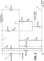
Figure 1 .- is an electric diagram of a preferred embodiment of the invention. -
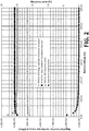
Figure 2 .- is a graph comparing the accuracy of the present invention with respect to prior art techniques. -
Figure 3 .- is another graph comparing measuring errors for different isolation resistances, using the technique of the invention and the US Standard FMVSS 305, for a constant battery voltage of 450V and R01=R02 = 200kohm. - A preferred embodiment of the invention is shown in
figures 1 , wherein it can be observed that the device comprises a positive high-voltage bus (1) connected with a positive pole of a battery (3) and additionally connected with a load (4). In turn, a negative high-voltage bus (2), which is the ground reference of the high-voltage circuit, is connected with a negative pole of the battery (3) and connected with another terminal of the load (4). - A first reference resistance (R01) is connected in series with a first switch (S1), and both components in series are connected between the positive high-voltage bus (1) and a low-voltage ground connection (5), for example a vehicle chassis. Similarly, a second reference resistance (R02) is connected in series with a second switch (S2), and both components in series are connected between the negative high-voltage bus (1) and the low-voltage ground connection (5).
- Furthermore, a first measurement resistance (Rbottom) has a first terminal connected with the low-voltage ground connection (5). A second measurement resistance (Rtop1) and a third switch (S3) are connected in series between the positive high-voltage bus (1), and the second terminal of the first measurement resistance (Rbottom). A third measurement resistance (Rtop2) and a fourth switch (S4) are both connected in series between the negative high-voltage bus (2), and the second terminal of the first measurement resistance (Rbottom).
- The device includes a control module adapted for opening and closing the first to the fourth switches (S1-S4) in accordance with a pre-established measurement sequence.
- In the first measurement position, the first switch (S1) is open, the second switch (S2) is open, the third switch (S3) is closed, and the fourth switch (S4) is open.
- In the second measurement position, the first switch (S1) is closed, the second switch (S2) is open, the third switch (S3) is closed, and the fourth switch (S4) is open.
- In the third measurement position, the first switch (S1) is open, the second switch (S2) is open, the third switch (S3) is open, and the fourth switch (S4) is closed.
- In the fourth measurement position, the first switch (S1) is open, the second switch (S2) is closed, the third switch (S3) is open, and the fourth switch (S4) is closed.
- The device further comprises a first voltage measurement device (not shown) connected for taking voltage measures at the first measuring resistance (Rbottom), and a second voltage measurement device (not shown) connected for measuring the voltage of the high-voltage battery (3).
- A calculating module (not shown) of the device, is communicated with the first and second voltage measuring devices, and it is adapted to measure and store, voltage measurements taken at the first measuring resistance (Rbottom), and voltage measurements taken of the high-voltage battery (3), in each one of the above-mentioned four measurement positions. The calculating module is additionally adapted to calculate the mean value of the four high-voltage battery (3) voltage measurements taken in measurements positions one to four.
- The calculating module calculates the isolation resistances of the battery powered system in according with the following formulas:


- Wherein:
- V_HV_mean is the mean value of the four high-voltage battery (3) voltage measurements taken respectively in each one of the four measurements positions,
- V2 is the voltage at the first measuring resistance (Rbottom) measured at the first measuring position,
- V2p is the voltage at the first measuring resistance (Rbottom) measured at the second measuring position,
- V1 is the voltage at the first measuring resistance (Rbottom) measured at the third measuring position,
- V1 p is the voltage at the first measuring resistance (Rbottom) measured at the fourth measuring position.
- Therefore, the calculating module is adapted for calculating an isolation resistance (Riso_pos) between the positive high-voltage bus (1) and the low-voltage ground (5), and an isolation resistance (Riso_neg) between the negative high-voltage bus and the a low-voltage ground, based on voltage measurements at the first measurement resistance (Rbottom), and based on voltage measurements of the high-voltage battery (3).
- The control and the calculating modules are implemented with an electronic programmable device, for example a micro-controller, adapted, that is, programmed to carry out the functions previously described.
- The method of the invention is also illustrated in
figure 1 , and comprises the following steps: - In a first measurement position, connecting a first and a second measurement resistances (Rbottom, Rtop1) in series between the positive high-voltage bus (1) and a low-voltage ground connection (5), and measuring voltage at the first measuring resistance (Rbottom), and voltage of the high-voltage battery (3).
- In a second measurement position, maintaining first and second measurement resistances (Rbottom, Rtop1) connected, and additionally connecting a first reference resistance (R01) between the positive high-voltage bus (1) and the low-voltage ground connection (5), and measuring voltage at the first measuring resistance (Rbottom), and voltage of the high-voltage battery (3).
- In a third measurement position, connecting a first and a third measurement resistances (Rbottom, Rtop2) in series between the negative high-voltage bus (2) and a low-voltage ground connection (5), and measuring voltage at the first measuring resistance (Rbottom), and voltage of the positive high-voltage battery (3).
- In a fourth measurement position, maintaining first and third measurement resistances (Rbottom, Rtop2) connected, and additionally connecting a second reference resistance (R02) between the negative high-voltage bus (1) and the low-voltage ground connection (5), and measuring voltage at the first measuring resistance (Rbottom), and voltage of the positive high-voltage battery (3).
- The method further comprises the step of calculating the mean value of the four high-voltage battery (3) voltage measurements, taken in the four measurements positions, and calculating the isolation resistances (Riso_pos, Riso_neg) of the battery powered system in according with the above formulas Riso_pos, and Riso_neg.
- The value of the first and second reference resistances (R01, R02) is calculated for each particular application, to improve accuracy in the range of the desired measures of the isolation resistances, as well as the expected battery voltage variations. Preferably, first and second reference resistances (R01, R02) have the same resistive value.
- The high-accuracy of the invention compared with the US Standard FMVSS-305 (with a battery nominal voltage of 450 volts), is shown in
figure 2 . Considering a Riso_neg constant value of 5Mohm, and a R01 =R02= 500 kohm. - In the following two simulations shows the accuracy of the invention with a battery voltage varying during the measures (V2, V2p, V1 and V1 p):
- Simulation 1.: Data: Battery nominal voltage =450 V; R01=R02 = 500kohm; Positive isolation resistance (Riso_pos) = 500kohm, Negative Isolation resistance (Riso_neg) = 1Mohm.
Voltage in each of the four measurements:- measurement 1: 450 V; measurement 2: 455V; measurement 3: 460 V; measurement 4: 465 V.
- Negative isolation resistance (Riso_neg) according to the invention: 0,99 Mohm.
- Negative isolation resistance (Riso_neg) according to the Standard FMVSS-305: 1.19 Mohm.
- Error with the invention: 1.17 %
- Error with the Standard FMVSS-305: 18,68 %.
- Simulation 2.: Data: Battery nominal voltage =450 V; R01R02 = 500Kohm; Positive isolation resistance (Riso_pos) = 1Mohm, Negative Isolation resistance (Riso_neg) = 2Mohm.
Voltage in each of the four measurements:- measurement 1: 450 V; measurement 2: 440V; measurement 3: 450 V; measurement 4: 460 V.
- Positive isolation resistance (Riso_pos) according to the invention: 0,96 Mohm.
- Positive isolation resistance (Riso_pos) according to the Standard FMVSS-305: 1.15 Mohm.
- Error with the invention: 3,91 %
- Error with the Standard FMVSS-305: 15,24 %.
Claims (11)
- Device for measuring isolation resistance (Riso_pos, Riso_neg) of a battery (3) powered system, the device comprising:a positive high-voltage bus (1) connectable to a positive pole of a battery (3), and additionally connectable to a load (4),a negative high-voltage bus (2) connectable to a negative pole of the battery (3), and additionally connectable to the load (4),a low-voltage ground connection (5),a first reference resistance (R01) and a first switch connected (S1) in series between the positive high-voltage bus (1) and the low-voltage ground connection (5),a second reference resistance (R02) and a second switch (S2) connected in series between the negative high-voltage bus (2) and the a low-voltage ground connection (5),a first measurement resistance (Rbottom) having a first terminal connected with the low-voltage ground connection (5),a second measurement resistance (Rtop1) and a third switch (S3) connected in series between the positive high-voltage bus (1), and the second terminal of the first measurement resistance (Rbottom),a third measurement resistance (Rtop2) and a fourth switch (S4) connected in series between the negative high-voltage bus (2), and the second terminal of the first measurement resistance (Rbottom),a control module adapted for opening and closing the first to the fourth switches (S1, S2, S3, S4) in accordance with a pre-established sequence,and a calculating module adapted for calculating an isolation resistance between the positive high-voltage bus (1) and the low-voltage ground (5), and an isolation resistance between the negative high-voltage bus (2) and the low-voltage ground (5), based on voltage measurements at the first measurement resistance (Rbottom), and voltage measurements of the high-voltage battery (3).
- Device according to claim 1 wherein the control module is additionally adapted to set the device in a first measurement position wherein:the first switch (S1) is openthe second switch (S2) is openthe third switch (S3) is closedthe fourth switch (S4) is openand wherein the calculating module is adapted to measure voltage at the first measuring resistance (Rbottom), and voltage at the high-voltage battery (3) in this first measurement position.
- Device according to claim 1 or 2, wherein the control module is additionally adapted to set the device in a second measurement position wherein:the first switch (S1) is closedthe second switch (S2) is openthe third switch (S3) is closedthe fourth switch (S4) is openand wherein the calculating module is adapted to measure voltage at the first measuring resistance (Rbottom), and voltage of the high-voltage battery (3) in this second measurement position.
- Device according to any of the preceding claims, wherein the control module is additionally adapted to set the device in a third measurement position wherein:the first switch (S1) is openthe second switch (S2) is openthe third switch (S3) is openthe fourth switch (S4) is closedand wherein the calculating module is adapted to measure voltage at the first measuring resistance (Rbottom), and voltage of the high-voltage battery (3) in this third measurement position.
- Device according to any of the preceding claims, wherein the control module is additionally adapted to set the device in a fourth measurement position wherein:the first switch (S1) is openthe second switch (S2) is closedthe third switch (S3) is openthe fourth switch (S4) is closedand wherein the calculating module is adapted to measure voltage at the first measuring resistance (Rbottom), and voltage of the positive high-voltage battery (3) in this fourth measurement position.
- Device according to any of the preceding claims, wherein the calculating module is additionally adapted to calculate the mean value of the four high-voltage battery voltage measurements, taken in measurements positions one to four.
- Device according to any of the preceding claims, wherein the calculating module is additionally adapted to calculate the isolation resistances (Riso_pos, Riso_neg) of the battery powered system in according with the formulas:

 V_HV_mean is the mean value of the four high-voltage battery voltage measurements taken in measurements positions one to four,V2 is the voltage at the first measuring resistance (Rbottom) measured at the first measuring position,V2p is the voltage at the first measuring resistance (Rbottom) measured at the second measuring position,V1 is the voltage at the first measuring resistance (Rbottom) measured at the third measuring position,V1p is the voltage at the first measuring resistance (Rbottom) measured at the fourth measuring position.
 - Electric vehicle incorporating a device according to any of the preceding claims, further comprising a battery (3) and device load (4), and wherein the positive high-voltage bus (1) and the negative high-voltage bus (2) are connected with the battery (3) and with the load (4), and wherein the low-voltage ground (5) is the vehicle chassis.
- Method for measuring isolation resistance (Riso_pos, Riso_neg) of a battery powered system, the battery powered system comprising: a battery (3), a load (4), and a positive high-voltage bus (1) and a negative high-voltage bus (2) connected between the battery (3) and the load (4), and a low-voltage ground connection (5), the method comprising the steps of:in a first measurement position, connecting a first and a second measurement resistance (Rbottom, Rtop1) in series between the positive high-voltage bus (1) and the low-voltage ground connection (5), and measuring voltage at the first measuring resistance (Rbottom), and voltage of the high-voltage battery(3),in a second measurement position, additionally to the first measurement position, connecting a first reference resistance (R01) between the positive high-voltage bus (1) and the low-voltage ground connection (5), and measuring voltage at the first measuring resistance (Rbottom), and voltage of the high-voltage battery (3),in a third measurement position, connecting a first and a third measurement resistance (Rbottom, Rtop2) in series between the negative high-voltage bus (2) and the low-voltage ground connection (5), and measuring voltage at the first measuring resistance (Rbottom), and voltage of the high-voltage battery (3),in a fourth measurement position, additionally to the third measurement position, connecting a second reference resistance (R02) between the negative high-voltage bus (2) and the low-voltage ground connection (5), and measuring voltage at the first measuring resistance (Rbottom), and voltage of the high-voltage battery (3).
- Method according to claim 9, further comprising the step of calculating the mean value of the four high-voltage battery voltage measurements taken in measurements positions one to four.
- Method according to claims 9 or 10, further comprising the steps of calculating isolation resistances (Riso_pos, Riso_neg) of the battery powered system in according with the formulas:

 V_HV_mean is the mean value of the four positive high-voltage bus voltage measurements taken in measurements positions one to four,V2 is the voltage at the first measuring resistance (Rbottom) measured at the first measuring position,V2p is the voltage at the first measuring resistance (Rbottom) measured at the second measuring position,V1 is the voltage at the first measuring resistance (Rbottom) measured at the third measuring position,V1 p is the voltage at the first measuring resistance (Rbottom) measured at the fourth measuring position.
Priority Applications (4)
| Application Number | Priority Date | Filing Date | Title |
|---|---|---|---|
| EP17382055.6A EP3361271B1 (en) | 2017-02-08 | 2017-02-08 | Device and method for measuring isolation resistance of battery powered systems |
| CN201810126804.4A CN108398598B (en) | 2017-02-08 | 2018-02-08 | Apparatus and method for measuring isolation resistance of battery powered system |
| JP2018020581A JP6959161B2 (en) | 2017-02-08 | 2018-02-08 | Devices and methods for measuring the insulation resistance of battery-powered systems |
| US15/891,948 US10632855B2 (en) | 2017-02-08 | 2018-02-08 | Device and method for measuring isolation resistance of battery powered systems |
Applications Claiming Priority (1)
| Application Number | Priority Date | Filing Date | Title |
|---|---|---|---|
| EP17382055.6A EP3361271B1 (en) | 2017-02-08 | 2017-02-08 | Device and method for measuring isolation resistance of battery powered systems |
Publications (2)
| Publication Number | Publication Date |
|---|---|
| EP3361271A1 true EP3361271A1 (en) | 2018-08-15 |
| EP3361271B1 EP3361271B1 (en) | 2022-06-01 |
Family
ID=58043997
Family Applications (1)
| Application Number | Title | Priority Date | Filing Date |
|---|---|---|---|
| EP17382055.6A Active EP3361271B1 (en) | 2017-02-08 | 2017-02-08 | Device and method for measuring isolation resistance of battery powered systems |
Country Status (4)
| Country | Link |
|---|---|
| US (1) | US10632855B2 (en) |
| EP (1) | EP3361271B1 (en) |
| JP (1) | JP6959161B2 (en) |
| CN (1) | CN108398598B (en) |
Cited By (3)
| Publication number | Priority date | Publication date | Assignee | Title |
|---|---|---|---|---|
| US10632855B2 (en) * | 2017-02-08 | 2020-04-28 | Fico Triad, S.A. | Device and method for measuring isolation resistance of battery powered systems |
| EP3933415A4 (en) * | 2019-11-18 | 2022-06-01 | LG Energy Solution, Ltd. | Apparatus for measuring insulation resistance and battery system using same |
| EP3985402A4 (en) * | 2020-07-27 | 2022-10-05 | Contemporary Amperex Technology Co., Limited | Insulation resistance detection circuit and method |
Families Citing this family (2)
| Publication number | Priority date | Publication date | Assignee | Title |
|---|---|---|---|---|
| CN109596885A (en) * | 2018-11-13 | 2019-04-09 | 浙江合众新能源汽车有限公司 | A kind of megger test method of REESS |
| US11275107B2 (en) * | 2019-12-10 | 2022-03-15 | GM Global Technology Operations LLC | Method and apparatus for monitoring isolation of an electric power bus |
Citations (8)
| Publication number | Priority date | Publication date | Assignee | Title |
|---|---|---|---|---|
| US20080224687A1 (en) * | 2007-03-12 | 2008-09-18 | Breese Richard M | Method and apparatus for monitoring fuel cells |
| KR20120057385A (en) * | 2010-11-26 | 2012-06-05 | 주식회사 케피코 | Detecting Apparatus Of Leakage Current For Electric Car |
| EP2616824A2 (en) * | 2010-09-17 | 2013-07-24 | SK Innovation Co., Ltd. | Insulation resistance measurement circuit having self-test function without generating leakage current |
| US20130257463A1 (en) * | 2012-03-28 | 2013-10-03 | Robert Bosch Gmbh | Circuit arrangement and method for monitoring electrical isolation |
| EP2796887A1 (en) * | 2012-03-27 | 2014-10-29 | LG Chem, Ltd. | Insulation resistance measurement device having malfuction self-diagnosis function, and method for self-diagnosing malfuction using same |
| EP2801837A1 (en) * | 2012-03-26 | 2014-11-12 | LG Chem, Ltd. | Device and method for measuring insulation resistance of battery |
| DE102013215731A1 (en) * | 2013-08-09 | 2015-02-12 | Volkswagen Aktiengesellschaft | Method and device for measuring one or more insulation resistances in a motor vehicle |
| US20150276846A1 (en) * | 2014-03-30 | 2015-10-01 | Seeo, Inc | High voltage isolation measurement system |
Family Cites Families (12)
| Publication number | Priority date | Publication date | Assignee | Title |
|---|---|---|---|---|
| EP2570289B1 (en) * | 2011-09-16 | 2018-08-15 | Samsung SDI Co., Ltd. | Device for determining the insulation resistance of a high-voltage battery system |
| US20130151355A1 (en) * | 2011-12-12 | 2013-06-13 | Idining, Inc. | Systems and methods for ordering goods or services |
| EP2720056B1 (en) * | 2012-04-04 | 2021-03-17 | LG Chem, Ltd. | Isolation resistance measuring apparatus having fault self-diagnosing function and self-diagnosing method using the same |
| JP6014404B2 (en) * | 2012-07-31 | 2016-10-25 | 株式会社ケーヒン | Earth leakage detector |
| US9164151B2 (en) * | 2013-08-07 | 2015-10-20 | Lg Chem, Ltd. | System and method for determining isolation resistances of a battery pack |
| US9783060B2 (en) * | 2014-05-15 | 2017-10-10 | Ford Global Technologies, Llc | Traction battery leakage detection system for electrified vehicle |
| US9758044B2 (en) * | 2014-10-02 | 2017-09-12 | Ford Global Technologies, Llc | Bus leakage resistance estimation for electrical isolation testing and diagnostics |
| KR101575271B1 (en) * | 2014-11-25 | 2015-12-07 | 현대오트론 주식회사 | Apparatus for measuring isolation resistance using logical operation and method thereof |
| US9645185B2 (en) * | 2015-03-05 | 2017-05-09 | Ford Global Technologies, Llc | AC traction motor fault detection using DC bus leakage hardware |
| JP6609984B2 (en) * | 2015-05-11 | 2019-11-27 | 富士電機株式会社 | Insulation resistance measuring method and apparatus |
| CN205015401U (en) * | 2015-09-30 | 2016-02-03 | 成都四威功率电子科技有限公司 | Electric automobile insulation resistance detection circuitry |
| EP3361271B1 (en) * | 2017-02-08 | 2022-06-01 | Fico Triad, S.A. | Device and method for measuring isolation resistance of battery powered systems |
-
2017
- 2017-02-08 EP EP17382055.6A patent/EP3361271B1/en active Active
-
2018
- 2018-02-08 US US15/891,948 patent/US10632855B2/en active Active
- 2018-02-08 CN CN201810126804.4A patent/CN108398598B/en active Active
- 2018-02-08 JP JP2018020581A patent/JP6959161B2/en active Active
Patent Citations (8)
| Publication number | Priority date | Publication date | Assignee | Title |
|---|---|---|---|---|
| US20080224687A1 (en) * | 2007-03-12 | 2008-09-18 | Breese Richard M | Method and apparatus for monitoring fuel cells |
| EP2616824A2 (en) * | 2010-09-17 | 2013-07-24 | SK Innovation Co., Ltd. | Insulation resistance measurement circuit having self-test function without generating leakage current |
| KR20120057385A (en) * | 2010-11-26 | 2012-06-05 | 주식회사 케피코 | Detecting Apparatus Of Leakage Current For Electric Car |
| EP2801837A1 (en) * | 2012-03-26 | 2014-11-12 | LG Chem, Ltd. | Device and method for measuring insulation resistance of battery |
| EP2796887A1 (en) * | 2012-03-27 | 2014-10-29 | LG Chem, Ltd. | Insulation resistance measurement device having malfuction self-diagnosis function, and method for self-diagnosing malfuction using same |
| US20130257463A1 (en) * | 2012-03-28 | 2013-10-03 | Robert Bosch Gmbh | Circuit arrangement and method for monitoring electrical isolation |
| DE102013215731A1 (en) * | 2013-08-09 | 2015-02-12 | Volkswagen Aktiengesellschaft | Method and device for measuring one or more insulation resistances in a motor vehicle |
| US20150276846A1 (en) * | 2014-03-30 | 2015-10-01 | Seeo, Inc | High voltage isolation measurement system |
Cited By (5)
| Publication number | Priority date | Publication date | Assignee | Title |
|---|---|---|---|---|
| US10632855B2 (en) * | 2017-02-08 | 2020-04-28 | Fico Triad, S.A. | Device and method for measuring isolation resistance of battery powered systems |
| EP3933415A4 (en) * | 2019-11-18 | 2022-06-01 | LG Energy Solution, Ltd. | Apparatus for measuring insulation resistance and battery system using same |
| US11841389B2 (en) | 2019-11-18 | 2023-12-12 | Lg Energy Solution, Ltd. | Apparatus for estimating insulation resistance and battery system using the same |
| EP3985402A4 (en) * | 2020-07-27 | 2022-10-05 | Contemporary Amperex Technology Co., Limited | Insulation resistance detection circuit and method |
| US11733279B2 (en) | 2020-07-27 | 2023-08-22 | Contemporary Amperex Technology Co., Limited | Circuit and method for detecting insulation resistance |
Also Published As
| Publication number | Publication date |
|---|---|
| JP2018128454A (en) | 2018-08-16 |
| CN108398598A (en) | 2018-08-14 |
| US10632855B2 (en) | 2020-04-28 |
| CN108398598B (en) | 2022-05-10 |
| EP3361271B1 (en) | 2022-06-01 |
| JP6959161B2 (en) | 2021-11-02 |
| US20180222342A1 (en) | 2018-08-09 |
Similar Documents
| Publication | Publication Date | Title |
|---|---|---|
| EP3361271B1 (en) | Device and method for measuring isolation resistance of battery powered systems | |
| JP5972972B2 (en) | DC power supply equipment | |
| US10391865B2 (en) | Electrical system comprising a circuit for detecting an electrical insulation fault | |
| KR101473396B1 (en) | Apparatus and method for measuring isolation resistance of battery using extended kalman filter | |
| US11879948B2 (en) | Electrical fault detection device and vehicle power supply system | |
| US10962597B2 (en) | Measurement apparatus, energy storage apparatus, measurement system, and offset error measurement method | |
| EP2848952A1 (en) | Device for estimating state of charge of battery | |
| US20140266222A1 (en) | Method and system for estimating voltage of a battery element | |
| KR101984326B1 (en) | Apparatus and method for measuring insulation resistance of battery | |
| JP2008058085A (en) | Short circuit detection method of battery pack for electric vehicle | |
| JP6033207B2 (en) | External short-circuit test apparatus and external short-circuit test method | |
| US11714119B2 (en) | Earth fault detection apparatus | |
| KR20210002971A (en) | Device for ground fault detection of electric car charger and method for the same | |
| US20220413061A1 (en) | Earth leakage detecting device, and vehicular power supply system | |
| US20170176509A1 (en) | Method for measuring electrical isolation of a vehicle chassis | |
| US20220404432A1 (en) | Earth leakage detection device and vehicle power supply system | |
| EP2487496A1 (en) | Method for isolation measurements using pre-charge and discharge circuitry | |
| CN115443412A (en) | Method for detecting an electrical insulation fault between a power supply and an electrical ground | |
| KR101734724B1 (en) | Apparatus for detecting electric leakage of electric vehicle | |
| D'Angelo et al. | Enhanced hotplug protection in BMS applications. Part I: Theoretical aspects and practical issues | |
| Dalala et al. | A current sensorless coulomb-counting method for enhanced battery state-of-charge estimation accuracy | |
| US11921167B2 (en) | Earth fault detection apparatus | |
| US11971458B2 (en) | Electrical fault detection device and vehicle power supply system | |
| CN209764949U (en) | Device for testing insulation resistance of high-voltage circuit of electric automobile | |
| Lee et al. | The maximum pulse current estimation for the lithium-ion battery |
Legal Events
| Date | Code | Title | Description |
|---|---|---|---|
| PUAI | Public reference made under article 153(3) epc to a published international application that has entered the european phase |
Free format text: ORIGINAL CODE: 0009012 |
|
| STAA | Information on the status of an ep patent application or granted ep patent |
Free format text: STATUS: THE APPLICATION HAS BEEN PUBLISHED |
|
| AK | Designated contracting states |
Kind code of ref document: A1 Designated state(s): AL AT BE BG CH CY CZ DE DK EE ES FI FR GB GR HR HU IE IS IT LI LT LU LV MC MK MT NL NO PL PT RO RS SE SI SK SM TR |
|
| AX | Request for extension of the european patent |
Extension state: BA ME |
|
| STAA | Information on the status of an ep patent application or granted ep patent |
Free format text: STATUS: REQUEST FOR EXAMINATION WAS MADE |
|
| 17P | Request for examination filed |
Effective date: 20190215 |
|
| RBV | Designated contracting states (corrected) |
Designated state(s): AL AT BE BG CH CY CZ DE DK EE ES FI FR GB GR HR HU IE IS IT LI LT LU LV MC MK MT NL NO PL PT RO RS SE SI SK SM TR |
|
| STAA | Information on the status of an ep patent application or granted ep patent |
Free format text: STATUS: REQUEST FOR EXAMINATION WAS MADE |
|
| GRAP | Despatch of communication of intention to grant a patent |
Free format text: ORIGINAL CODE: EPIDOSNIGR1 |
|
| STAA | Information on the status of an ep patent application or granted ep patent |
Free format text: STATUS: GRANT OF PATENT IS INTENDED |
|
| RIC1 | Information provided on ipc code assigned before grant |
Ipc: G01R 31/00 20060101ALN20211203BHEP Ipc: B60L 58/10 20190101ALI20211203BHEP Ipc: B60L 3/12 20060101ALI20211203BHEP Ipc: B60L 3/00 20190101ALI20211203BHEP Ipc: G01R 31/52 20200101ALI20211203BHEP Ipc: G01R 27/02 20060101AFI20211203BHEP |
|
| INTG | Intention to grant announced |
Effective date: 20211223 |
|
| GRAS | Grant fee paid |
Free format text: ORIGINAL CODE: EPIDOSNIGR3 |
|
| GRAA | (expected) grant |
Free format text: ORIGINAL CODE: 0009210 |
|
| STAA | Information on the status of an ep patent application or granted ep patent |
Free format text: STATUS: THE PATENT HAS BEEN GRANTED |
|
| AK | Designated contracting states |
Kind code of ref document: B1 Designated state(s): AL AT BE BG CH CY CZ DE DK EE ES FI FR GB GR HR HU IE IS IT LI LT LU LV MC MK MT NL NO PL PT RO RS SE SI SK SM TR |
|
| REG | Reference to a national code |
Ref country code: GB Ref legal event code: FG4D |
|
| REG | Reference to a national code |
Ref country code: AT Ref legal event code: REF Ref document number: 1495742 Country of ref document: AT Kind code of ref document: T Effective date: 20220615 Ref country code: CH Ref legal event code: EP |
|
| REG | Reference to a national code |
Ref country code: IE Ref legal event code: FG4D |
|
| REG | Reference to a national code |
Ref country code: DE Ref legal event code: R096 Ref document number: 602017057963 Country of ref document: DE |
|
| REG | Reference to a national code |
Ref country code: LT Ref legal event code: MG9D |
|
| REG | Reference to a national code |
Ref country code: NL Ref legal event code: MP Effective date: 20220601 |
|
| PG25 | Lapsed in a contracting state [announced via postgrant information from national office to epo] |
Ref country code: SE Free format text: LAPSE BECAUSE OF FAILURE TO SUBMIT A TRANSLATION OF THE DESCRIPTION OR TO PAY THE FEE WITHIN THE PRESCRIBED TIME-LIMIT Effective date: 20220601 Ref country code: NO Free format text: LAPSE BECAUSE OF FAILURE TO SUBMIT A TRANSLATION OF THE DESCRIPTION OR TO PAY THE FEE WITHIN THE PRESCRIBED TIME-LIMIT Effective date: 20220901 Ref country code: LT Free format text: LAPSE BECAUSE OF FAILURE TO SUBMIT A TRANSLATION OF THE DESCRIPTION OR TO PAY THE FEE WITHIN THE PRESCRIBED TIME-LIMIT Effective date: 20220601 Ref country code: HR Free format text: LAPSE BECAUSE OF FAILURE TO SUBMIT A TRANSLATION OF THE DESCRIPTION OR TO PAY THE FEE WITHIN THE PRESCRIBED TIME-LIMIT Effective date: 20220601 Ref country code: GR Free format text: LAPSE BECAUSE OF FAILURE TO SUBMIT A TRANSLATION OF THE DESCRIPTION OR TO PAY THE FEE WITHIN THE PRESCRIBED TIME-LIMIT Effective date: 20220902 Ref country code: FI Free format text: LAPSE BECAUSE OF FAILURE TO SUBMIT A TRANSLATION OF THE DESCRIPTION OR TO PAY THE FEE WITHIN THE PRESCRIBED TIME-LIMIT Effective date: 20220601 Ref country code: ES Free format text: LAPSE BECAUSE OF FAILURE TO SUBMIT A TRANSLATION OF THE DESCRIPTION OR TO PAY THE FEE WITHIN THE PRESCRIBED TIME-LIMIT Effective date: 20220601 Ref country code: BG Free format text: LAPSE BECAUSE OF FAILURE TO SUBMIT A TRANSLATION OF THE DESCRIPTION OR TO PAY THE FEE WITHIN THE PRESCRIBED TIME-LIMIT Effective date: 20220901 |
|
| REG | Reference to a national code |
Ref country code: AT Ref legal event code: MK05 Ref document number: 1495742 Country of ref document: AT Kind code of ref document: T Effective date: 20220601 |
|
| PG25 | Lapsed in a contracting state [announced via postgrant information from national office to epo] |
Ref country code: RS Free format text: LAPSE BECAUSE OF FAILURE TO SUBMIT A TRANSLATION OF THE DESCRIPTION OR TO PAY THE FEE WITHIN THE PRESCRIBED TIME-LIMIT Effective date: 20220601 Ref country code: PL Free format text: LAPSE BECAUSE OF FAILURE TO SUBMIT A TRANSLATION OF THE DESCRIPTION OR TO PAY THE FEE WITHIN THE PRESCRIBED TIME-LIMIT Effective date: 20220601 Ref country code: LV Free format text: LAPSE BECAUSE OF FAILURE TO SUBMIT A TRANSLATION OF THE DESCRIPTION OR TO PAY THE FEE WITHIN THE PRESCRIBED TIME-LIMIT Effective date: 20220601 |
|
| PG25 | Lapsed in a contracting state [announced via postgrant information from national office to epo] |
Ref country code: NL Free format text: LAPSE BECAUSE OF FAILURE TO SUBMIT A TRANSLATION OF THE DESCRIPTION OR TO PAY THE FEE WITHIN THE PRESCRIBED TIME-LIMIT Effective date: 20220601 |
|
| PG25 | Lapsed in a contracting state [announced via postgrant information from national office to epo] |
Ref country code: SM Free format text: LAPSE BECAUSE OF FAILURE TO SUBMIT A TRANSLATION OF THE DESCRIPTION OR TO PAY THE FEE WITHIN THE PRESCRIBED TIME-LIMIT Effective date: 20220601 Ref country code: SK Free format text: LAPSE BECAUSE OF FAILURE TO SUBMIT A TRANSLATION OF THE DESCRIPTION OR TO PAY THE FEE WITHIN THE PRESCRIBED TIME-LIMIT Effective date: 20220601 Ref country code: RO Free format text: LAPSE BECAUSE OF FAILURE TO SUBMIT A TRANSLATION OF THE DESCRIPTION OR TO PAY THE FEE WITHIN THE PRESCRIBED TIME-LIMIT Effective date: 20220601 Ref country code: PT Free format text: LAPSE BECAUSE OF FAILURE TO SUBMIT A TRANSLATION OF THE DESCRIPTION OR TO PAY THE FEE WITHIN THE PRESCRIBED TIME-LIMIT Effective date: 20221003 Ref country code: EE Free format text: LAPSE BECAUSE OF FAILURE TO SUBMIT A TRANSLATION OF THE DESCRIPTION OR TO PAY THE FEE WITHIN THE PRESCRIBED TIME-LIMIT Effective date: 20220601 Ref country code: CZ Free format text: LAPSE BECAUSE OF FAILURE TO SUBMIT A TRANSLATION OF THE DESCRIPTION OR TO PAY THE FEE WITHIN THE PRESCRIBED TIME-LIMIT Effective date: 20220601 Ref country code: AT Free format text: LAPSE BECAUSE OF FAILURE TO SUBMIT A TRANSLATION OF THE DESCRIPTION OR TO PAY THE FEE WITHIN THE PRESCRIBED TIME-LIMIT Effective date: 20220601 |
|
| PG25 | Lapsed in a contracting state [announced via postgrant information from national office to epo] |
Ref country code: IS Free format text: LAPSE BECAUSE OF FAILURE TO SUBMIT A TRANSLATION OF THE DESCRIPTION OR TO PAY THE FEE WITHIN THE PRESCRIBED TIME-LIMIT Effective date: 20221001 |
|
| REG | Reference to a national code |
Ref country code: DE Ref legal event code: R097 Ref document number: 602017057963 Country of ref document: DE |
|
| PG25 | Lapsed in a contracting state [announced via postgrant information from national office to epo] |
Ref country code: AL Free format text: LAPSE BECAUSE OF FAILURE TO SUBMIT A TRANSLATION OF THE DESCRIPTION OR TO PAY THE FEE WITHIN THE PRESCRIBED TIME-LIMIT Effective date: 20220601 |
|
| PLBE | No opposition filed within time limit |
Free format text: ORIGINAL CODE: 0009261 |
|
| STAA | Information on the status of an ep patent application or granted ep patent |
Free format text: STATUS: NO OPPOSITION FILED WITHIN TIME LIMIT |
|
| PG25 | Lapsed in a contracting state [announced via postgrant information from national office to epo] |
Ref country code: DK Free format text: LAPSE BECAUSE OF FAILURE TO SUBMIT A TRANSLATION OF THE DESCRIPTION OR TO PAY THE FEE WITHIN THE PRESCRIBED TIME-LIMIT Effective date: 20220601 |
|
| 26N | No opposition filed |
Effective date: 20230302 |
|
| PG25 | Lapsed in a contracting state [announced via postgrant information from national office to epo] |
Ref country code: SI Free format text: LAPSE BECAUSE OF FAILURE TO SUBMIT A TRANSLATION OF THE DESCRIPTION OR TO PAY THE FEE WITHIN THE PRESCRIBED TIME-LIMIT Effective date: 20220601 |
|
| PGFP | Annual fee paid to national office [announced via postgrant information from national office to epo] |
Ref country code: DE Payment date: 20230216 Year of fee payment: 7 |
|
| PG25 | Lapsed in a contracting state [announced via postgrant information from national office to epo] |
Ref country code: MC Free format text: LAPSE BECAUSE OF FAILURE TO SUBMIT A TRANSLATION OF THE DESCRIPTION OR TO PAY THE FEE WITHIN THE PRESCRIBED TIME-LIMIT Effective date: 20220601 |
|
| REG | Reference to a national code |
Ref country code: CH Ref legal event code: PL |
|
| REG | Reference to a national code |
Ref country code: BE Ref legal event code: MM Effective date: 20230228 |
|
| GBPC | Gb: european patent ceased through non-payment of renewal fee |
Effective date: 20230208 |
|
| PG25 | Lapsed in a contracting state [announced via postgrant information from national office to epo] |
Ref country code: LU Free format text: LAPSE BECAUSE OF NON-PAYMENT OF DUE FEES Effective date: 20230208 Ref country code: LI Free format text: LAPSE BECAUSE OF NON-PAYMENT OF DUE FEES Effective date: 20230228 Ref country code: CH Free format text: LAPSE BECAUSE OF NON-PAYMENT OF DUE FEES Effective date: 20230228 |
|
| REG | Reference to a national code |
Ref country code: IE Ref legal event code: MM4A |
|
| PG25 | Lapsed in a contracting state [announced via postgrant information from national office to epo] |
Ref country code: GB Free format text: LAPSE BECAUSE OF NON-PAYMENT OF DUE FEES Effective date: 20230208 |
|
| PG25 | Lapsed in a contracting state [announced via postgrant information from national office to epo] |
Ref country code: IT Free format text: LAPSE BECAUSE OF FAILURE TO SUBMIT A TRANSLATION OF THE DESCRIPTION OR TO PAY THE FEE WITHIN THE PRESCRIBED TIME-LIMIT Effective date: 20220601 Ref country code: IE Free format text: LAPSE BECAUSE OF NON-PAYMENT OF DUE FEES Effective date: 20230208 Ref country code: GB Free format text: LAPSE BECAUSE OF NON-PAYMENT OF DUE FEES Effective date: 20230208 Ref country code: FR Free format text: LAPSE BECAUSE OF NON-PAYMENT OF DUE FEES Effective date: 20230228 |
|
| PG25 | Lapsed in a contracting state [announced via postgrant information from national office to epo] |
Ref country code: BE Free format text: LAPSE BECAUSE OF NON-PAYMENT OF DUE FEES Effective date: 20230228 |